EP2763010A1 - Mobile information processing terminal - Google Patents
Mobile information processing terminal Download PDFInfo
- Publication number
- EP2763010A1 EP2763010A1 EP20120835441 EP12835441A EP2763010A1 EP 2763010 A1 EP2763010 A1 EP 2763010A1 EP 20120835441 EP20120835441 EP 20120835441 EP 12835441 A EP12835441 A EP 12835441A EP 2763010 A1 EP2763010 A1 EP 2763010A1
- Authority
- EP
- European Patent Office
- Prior art keywords
- display
- touch screen
- display device
- information processing
- control part
- Prior art date
- Legal status (The legal status is an assumption and is not a legal conclusion. Google has not performed a legal analysis and makes no representation as to the accuracy of the status listed.)
- Withdrawn
Links
Images







Classifications
-
- G—PHYSICS
- G06—COMPUTING OR CALCULATING; COUNTING
- G06F—ELECTRIC DIGITAL DATA PROCESSING
- G06F3/00—Input arrangements for transferring data to be processed into a form capable of being handled by the computer; Output arrangements for transferring data from processing unit to output unit, e.g. interface arrangements
- G06F3/01—Input arrangements or combined input and output arrangements for interaction between user and computer
- G06F3/03—Arrangements for converting the position or the displacement of a member into a coded form
- G06F3/041—Digitisers, e.g. for touch screens or touch pads, characterised by the transducing means
-
- G—PHYSICS
- G06—COMPUTING OR CALCULATING; COUNTING
- G06F—ELECTRIC DIGITAL DATA PROCESSING
- G06F3/00—Input arrangements for transferring data to be processed into a form capable of being handled by the computer; Output arrangements for transferring data from processing unit to output unit, e.g. interface arrangements
- G06F3/01—Input arrangements or combined input and output arrangements for interaction between user and computer
- G06F3/048—Interaction techniques based on graphical user interfaces [GUI]
- G06F3/0487—Interaction techniques based on graphical user interfaces [GUI] using specific features provided by the input device, e.g. functions controlled by the rotation of a mouse with dual sensing arrangements, or of the nature of the input device, e.g. tap gestures based on pressure sensed by a digitiser
-
- G—PHYSICS
- G06—COMPUTING OR CALCULATING; COUNTING
- G06F—ELECTRIC DIGITAL DATA PROCESSING
- G06F1/00—Details not covered by groups G06F3/00 - G06F13/00 and G06F21/00
- G06F1/16—Constructional details or arrangements
- G06F1/1613—Constructional details or arrangements for portable computers
- G06F1/1633—Constructional details or arrangements of portable computers not specific to the type of enclosures covered by groups G06F1/1615 - G06F1/1626
- G06F1/1684—Constructional details or arrangements related to integrated I/O peripherals not covered by groups G06F1/1635 - G06F1/1675
-
- G—PHYSICS
- G06—COMPUTING OR CALCULATING; COUNTING
- G06F—ELECTRIC DIGITAL DATA PROCESSING
- G06F1/00—Details not covered by groups G06F3/00 - G06F13/00 and G06F21/00
- G06F1/16—Constructional details or arrangements
- G06F1/1613—Constructional details or arrangements for portable computers
- G06F1/1633—Constructional details or arrangements of portable computers not specific to the type of enclosures covered by groups G06F1/1615 - G06F1/1626
- G06F1/1684—Constructional details or arrangements related to integrated I/O peripherals not covered by groups G06F1/1635 - G06F1/1675
- G06F1/1686—Constructional details or arrangements related to integrated I/O peripherals not covered by groups G06F1/1635 - G06F1/1675 the I/O peripheral being an integrated camera
-
- G—PHYSICS
- G06—COMPUTING OR CALCULATING; COUNTING
- G06F—ELECTRIC DIGITAL DATA PROCESSING
- G06F1/00—Details not covered by groups G06F3/00 - G06F13/00 and G06F21/00
- G06F1/16—Constructional details or arrangements
- G06F1/1613—Constructional details or arrangements for portable computers
- G06F1/1633—Constructional details or arrangements of portable computers not specific to the type of enclosures covered by groups G06F1/1615 - G06F1/1626
- G06F1/1684—Constructional details or arrangements related to integrated I/O peripherals not covered by groups G06F1/1635 - G06F1/1675
- G06F1/1694—Constructional details or arrangements related to integrated I/O peripherals not covered by groups G06F1/1635 - G06F1/1675 the I/O peripheral being a single or a set of motion sensors for pointer control or gesture input obtained by sensing movements of the portable computer
-
- G—PHYSICS
- G06—COMPUTING OR CALCULATING; COUNTING
- G06F—ELECTRIC DIGITAL DATA PROCESSING
- G06F3/00—Input arrangements for transferring data to be processed into a form capable of being handled by the computer; Output arrangements for transferring data from processing unit to output unit, e.g. interface arrangements
- G06F3/01—Input arrangements or combined input and output arrangements for interaction between user and computer
- G06F3/011—Arrangements for interaction with the human body, e.g. for user immersion in virtual reality
- G06F3/012—Head tracking input arrangements
-
- G—PHYSICS
- G06—COMPUTING OR CALCULATING; COUNTING
- G06F—ELECTRIC DIGITAL DATA PROCESSING
- G06F2200/00—Indexing scheme relating to G06F1/04 - G06F1/32
- G06F2200/16—Indexing scheme relating to G06F1/16 - G06F1/18
- G06F2200/163—Indexing scheme relating to constructional details of the computer
- G06F2200/1637—Sensing arrangement for detection of housing movement or orientation, e.g. for controlling scrolling or cursor movement on the display of an handheld computer
-
- G—PHYSICS
- G06—COMPUTING OR CALCULATING; COUNTING
- G06F—ELECTRIC DIGITAL DATA PROCESSING
- G06F2203/00—Indexing scheme relating to G06F3/00 - G06F3/048
- G06F2203/041—Indexing scheme relating to G06F3/041 - G06F3/045
- G06F2203/04101—2.5D-digitiser, i.e. digitiser detecting the X/Y position of the input means, finger or stylus, also when it does not touch, but is proximate to the digitiser's interaction surface and also measures the distance of the input means within a short range in the Z direction, possibly with a separate measurement setup
-
- G—PHYSICS
- G06—COMPUTING OR CALCULATING; COUNTING
- G06F—ELECTRIC DIGITAL DATA PROCESSING
- G06F2203/00—Indexing scheme relating to G06F3/00 - G06F3/048
- G06F2203/041—Indexing scheme relating to G06F3/041 - G06F3/045
- G06F2203/04108—Touchless 2D- digitiser, i.e. digitiser detecting the X/Y position of the input means, finger or stylus, also when it does not touch, but is proximate to the digitiser's interaction surface without distance measurement in the Z direction
Definitions
- the present invention relates to a mobile information processing terminal, more specifically, relates to a mobile information processing terminal that has a touch screen.
- Patent Document 1 discloses a technique of imaging the face of a user of a mobile terminal to detect the orientation of the user and controlling the display orientation of a display part depending on the orientation of the user.
- Patent Document 1 Japanese Unexamined Patent Application Publication No. 2007-017596
- an object of the present invention is to solve the abovementioned problem, degradation of the visibility and operability of an information processing terminal equipped with a touch screen display device.
- a program as another exemplary embodiment of the present invention is a computer program including instructions for causing an information processing terminal including a touch screen display device to realize:
- a display control method as another exemplary embodiment of the present invention is a display control method by an information processing terminal including a touch screen display device, the display control method including:
- the present invention achieves increase of the operability of an information processing terminal equipped with a touch screen display device.
- FIGs. 1A to 7 a first exemplary embodiment of the present invention will be described.
- Figs. 1A to 2 are diagrams showing the configuration of a mobile terminal in this exemplary embodiment.
- Figs. 3 to 4B are diagrams for describing an operation to recognize an operator by the mobile terminal.
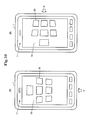
- Figs. 5A to 6B are diagrams showing examples of display of a display screen by the mobile terminal.
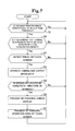
- Fig. 7 is a flowchart showing an operation by the mobile terminal.
- Figs. 1A and 1B are diagrams showing the exterior of a mobile terminal 1 according to the present invention.
- Fig. 1A and 1B show exteriors taken from one face (a front face) and the other face (a rear face) of the mobile terminal 1, respectively.
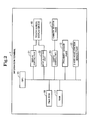
- Fig. 2 is a block diagram showing the circuit configuration of the mobile terminal 1.
- the mobile terminal is a general information processing terminal that includes a CPU 15 as a central processing unit, and a Flash Rom 16 and a RAM 17 as storage devices storing various kinds of data.
- the CPU 15 is connected with circuits and devices in the terminal via a bus as described later.
- the Flash ROM 16 is a rewritable storage memory that stores various kinds of control programs executed by the CPU 15 and user data.
- the RAM (Random Access Memory) 17 is a working memory that stores data temporarily necessary for the CPU 15 to execute the programs.
- the mobile terminal 1 is a mobile phone terminal such as a so-called smartphone
- the mobile terminal 1 according to the present invention may be any information processing device, such as a PHS (Personal Handy-phone System), a PDA (Personal Data Assistance, Personal Digital Assistants: personal mobile information communication equipment), a tablet terminal, a personal computer, a game terminal, an electronic dictionary, and a car navigation system.
- a PHS Personal Handy-phone System
- PDA Personal Digital Assistants: personal mobile information communication equipment
- tablet terminal a personal computer
- game terminal a game terminal
- an electronic dictionary an electronic dictionary
- the mobile terminal 1 includes a touch screen display device 10 on the front face.
- This touch screen display device 10 includes an input device, such as an electrostatic touch screen, that accepts a contact input by an operator, and a display device such as a liquid crystal panel or an organic EL. A display face of the display device configures the input device of the touch screen.
- the mobile terminal 1 includes a display control part (a control device) 21 that controls a display state on the display device configuring the touch screen display device 10.
- This display control part 21, which is connected to the CPU 15, controls the display state of display data such as an icon displayed on a display screen of the touch screen display device 10, in accordance with a position (a specific position) of the operator detected as described later.
- the display control part 21 is structured by installation of a program into the CPU 15, or structured by a dedicated arithmetic device.
- the mobile terminal 1 includes an input detecting part (a contact detecting part) 22 that detects a contact input to the input device configuring the touch screen display device 1.
- This input detecting part 22 which is connected to the CPU 15, detects and accepts a contact input at a display site of display data such as an icon displayed on the display screen as described later. That is, the input detecting part 22 has a function of, when a display region such as a display area or a display range of display data changes, detecting a contact input within the display range.
- the input detecting part 22 is structured by installation of a program into the CPU 15, or structured by a dedicated arithmetic device.
- the mobile terminal 1 has a camera sensor part 11 that captures an image on one face, which is the face with the touch screen display device 10 provided.
- the camera sensor part 11 is an imaging device such as a CCD image sensor or a CMOS sensor.
- the mobile terminal 1 includes a camera control part 23, which is a circuit controlling the camera sensor part 11, namely, the imaging device.
- This camera control part 23 sends captured image data to the CPU 15, and the CPU 15 detects the position of the operator as the specific position from the data content of the image data as described later. That is, the camera sensor part 11, the camera control part 23, and the CPU 15 function as a position detecting means for detecting the position of the operator in cooperation with each other.
- the position detecting means recognizes the person as the operator and detects the operator's position as the specific position.
- the position detecting means may detect another object from the image data and detect the object's position as the specific position.
- the mobile terminal 1 includes a proximity sensor part 12 on the other face, which is the opposite face to the face with the touch screen display device 10 provided.
- This proximity sensor part 12 which is a sensor detecting a distance from an object, detects that the mobile terminal 1 is in contact with a plane such as a board of a desk D or a wall and notifies it to the CPU 15, for example, when a distance from an object is equal to or less than a criterion value.
- the mobile terminal 1 includes a 3-axis acceleration sensor part 13 inside thereof.
- This 3-axis acceleration sensor part 13 detects acceleration of the mobile terminal 1 in directions of the three axes with respect to the Earth's gravity to detect an inclination angle of the mobile terminal 1 with respect to the horizontal face, and notifies it to the CPU 15.
- the CPU 15 detects that the mobile terminal 1 is kept placed horizontally on a given board. That is, the proximity sensor part 12, the 3-axis acceleration sensor part 13, and the CPU 15 function as a horizontal state detecting means for detecting that the mobile terminal 1 is in the horizontal state in cooperation with each other.
- the horizontal state in the present invention includes a case where the inclination angle of the mobile terminal 1 with respect to the horizontal face detected by the 3-axis acceleration sensor part 13 described above is within a previously set range (e.g., within a range of 5 degrees with respect to the horizontal face).
- a condition for determining that the mobile terminal 1 is in the horizontal state is not necessarily that the mobile terminal 1 is placed on an object such as a board. That is, the mobile terminal 1 does not necessarily include the proximity sensor part 12.
- the means for detecting that the mobile terminal 1 is in the horizontal state is not necessarily realized by the abovementioned configuration, and may be realized by another configuration.
- the position detecting means configured by the camera sensor part 11, the CPU 15 and so on executes an image recognition process on image data captured by the camera sensor part 11, and identifies which direction the operator is located in.
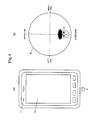
- image data of a range shown by symbol R in Figs. 3 and 4B is acquired by the camera sensor part 11 placed at the upper end part of the mobile terminal 1 as shown in Fig. 3 .
- the image recognition process on the image data is executed by the CPU 15, and a process of detecting a person (a face) is executed.
- matching with previously stored human face characteristic data or detection of a characteristic portion such as an eye or a mouth of a human by a statistical method is executed.
- a characteristic portion such as an eye or a mouth of a human by a statistical method
- the position detecting means detects that the operator U is located in the horizontal direction with respect to the mobile terminal 1 as shown in Fig. 3 and located on the lower end side in Fig. 4A .
- the operator U is located on an end side of a specific direction within the imaging range R shown in Fig. 4B , it is detected that the operator U is located on the end side and in a direction horizontal to the mobile terminal 1.
- the operator U is located in the center of the imaging range R, it is detected that the operator U is vertically above the mobile terminal 1.
- the abovementioned detection of the position of the operator U is not necessarily performed by using a captured image. It may be performed by using another configuration capable of detecting a person, such as an infrared sensor. Moreover, by another configuration without using an image, the position of a detected object other than a person may be detected as the specific position.
- the display control part 21 changes the display state of the display screen of the touch screen display device 10 and displays the display screen.
- the display control part 21 recognizes that the display screen is visually recognized from an end side of a specific direction of the mobile terminal 1 where the operator U is located, and changes the display orientation of the display data displayed on the touch screen display device 10 so that the end side becomes the lower side of the display screen.
- the display control part 21 further changes the display state of the display data depending on a distance from the detected position of the operator U (the specific position) to the display region occupied by the display data on the display screen of the touch screen display device 10.
- the display control part 21 changes the display state of icons and the entire screen.
- Figs. 5A to 6B Examples of change of the display status of the image data displayed on the display screen by the display control part 21 in this exemplary embodiment are shown in Figs. 5A to 6B .
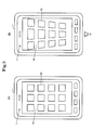
- the display control part 21 controls so that, as a normal display state, a plurality of rectangular icons 20 are displayed on the display screen of the touch screen display device 10 as shown in Fig. 5A .
- the display data is displayed in a display orientation that the lower side of the display data faces downward in Fig. 5A .
- the display control part 21 firstly determines that the operator U is viewing from an arrow direction on the lower end side, and changes the display orientation of the data displayed on the touch screen display device 10 so that the lower end side becomes the lower side of the display screen. In the example shown in Fig. 5B , however, the display orientation is not changed from that in Fig. 5A .
- the shape of the icons 20 is described as rectangular above, a description will be further made assuming the shape is square hereinafter. However, the shape of the icons 20 is not limited to a rectangular shape and may be any shape, for example, a circular shape.
- the display control part 21 changes the display shapes of the respective square-shaped icons 20 that are the display data displayed on the display screen to trapezoidal shapes so that the icons 20 becomes larger as a distance from the specific end of the mobile terminal 1 becomes longer, and displays the display screen as shown in Fig. 5B . That is, the display control part 21 changes the display shape of each of the icons 20 to a trapezoidal shape whose width closer to the operator U is shorter and whose width farther from the operator U is longer as compared with in the normal display state, and displays the display screen. Moreover, the display control part 21 increases the display sizes of the trapezoids of the icons 20 located farther from the operator U, and displays the display screen.
- the icons 20 are displayed so that the operator U can feel a stronger sense of perspective, and the operator U can visually recognize the icons 20 located farther.
- the display control part 21 changes the shape of the icon 20 to a trapezoidal shape in accordance with a distance between a display position of the icon 20 and the end of the mobile terminal 1 is described herein, the display control part 21 may change the shape to a shape similar to a parallelogram in accordance with a display position of the icon 20.
- the display control part 21 specifies a direction of a distance from a specific end of the mobile terminal 1 where the operator is located to each of the icons 20, and determines a relative position of each of the icons 20 with respect to the direction of the distance. For example, the display control part 21 determines the icon 20 in the farthest position and the icon 20 in the nearest position with respect to the direction of the distance as the distal icon 20 and the proximal icon 20, respectively. All of the icons displayed in parallel to the specific end of the mobile terminal 1 may be considered to be in equal positions with respect to the direction of the distance. Then, in accordance with the relative position of each of the icons 20 with respect to the specific end, the display control part 21 executes a display mode changing process on each of the icons 20.
- This display mode changing process is a process of, for example, performing shape change so that the respective icons 20 have trapezoidal shapes as described above and then performing size change so that the rate of the data size of each of the icons 20 becomes smaller in the proximal position than in the distal position or becomes larger in the distal position than in the proximal position.
- the display control part 21 may execute only either the shape changing process or the scaling process described above.
- Change of the display state of the icons 20 shown in Fig. 5B is an example, and the display control part 21 may change to another shape and display. Moreover, the display control part 21 does not need to change the size of the icon 20 necessarily, and may change an image element added to the icon 20 as described in another exemplary embodiment. Furthermore, although a case of changing the shape of each of the icons 20 and displaying is illustrated above, it is also possible to change display data 20' displayed on the entire touch screen display device 10 as shown in Fig. 6A to a state as shown in Fig. 6B that the width of the whole screen becomes gradually shorter toward an end side where the operator U is located and the width of the whole screen becomes gradually longer toward the opposite end side to the abovementioned end side.
- the display control part 21 determines a distal position and a proximal position of the whole screen in a direction of a distance from a specific end of the mobile terminal 1 to the screen, decreases the rate of the data size of the whole screen from the distal position to the proximal position or increases the rate from the proximal position to the distal position, and displays the display screen.
- the input detecting part 22 executes a process of changing a range to detect a contact input to the icons 20. That is, the input detecting part 22 accepts a contact input when detecting the contact input on the square-shaped icon 20 in the normal display state shown in Fig. 5A , but after the display state is changed as shown in Fig. 5B , detects a contact input within a shape range of the trapezoidal-shaped icon 20 and accepts the input.
- the display state changing process by the display control part 21 described above may be executed depending on the position of the operator U even when the touch screen display device 10 of the mobile terminal 1 is not located in the horizontal state.
- the proximate sensor 12 placed on the rear face of the mobile terminal 1 detects its distance from a proximate object.
- the distance from the proximate object is equal to or less than a previously set threshold, it is determined that the mobile terminal 1 is in contact with the proximate object (step S1: Yes).
- a placement angle of the mobile terminal 1 is detected from a value detected by the 3-axis acceleration sensor 13 included by the mobile terminal 1.
- the placement angle of the mobile terminal 1 is within a previously set threshold with respect to an angle perpendicular to the direction of the Earth's gravity, it is determined that the mobile terminal 1 is placed horizontally (step S2: Yes).
- step S3 In a case where there is a contact input (a press) on the touch screen display device 10 in a state that the mobile terminal 1 is in contact with the proximate object and placed horizontally as described above (step S3: Yes), the camera sensor part 11 placed on the front face of the mobile terminal 1 is caused to operate (step S4). Then, imaging information acquired by the camera sensor part 11 is converted into two-dimensional image data and outputted by the camera control part 23 (step S4).
- the image data outputted by the camera control part 23 is sent to the RAM 17 and subjected to the image recognition process by the CPU 15, and it is thereby identified which direction of the mobile terminal 1 the operator U is located in.
- the operator U when it is identified that the operator U is located in the center part of the captured image data, it is determined that the operator U is vertically above the mobile terminal 1.
- it is determined that the operator U is operating from a position nearly horizontal to the specific direction of the mobile terminal 1 (step S5: Yes). For example, in the example shown in Fig.
- step S6 the display state of the display screen of the touch screen display device 10 is changed. For example, when it is identified that the operator U is located on the lower end side of the mobile terminal 1 as shown by arrow in Fig. 5B , the display orientation is firstly changed so that the lower end side of the mobile terminal 1 becomes the lower side of the display screen.
- the display screen is then changed to a trapezoidal-shaped display screen that the length in the width direction on the lower side of the screen display located on the side of the operator U, namely, on the near side from the operator U is shorter and the length in the width direction on the upper side of the screen display located on the farther side from the operator U is longer, as compared with the normal display state shown in Fig. 5A . Consequently, the operator can more easily view the screen display located far from him/her.
- the shape of an operation area to detect a contact input on the touch screen display device 10 is also changed to a trapezoidal shape so as to correspond to the abovementioned display area (step S7). Consequently, the operator U can perform operation corresponding to the screen display, and can operate with ease.
- the operator U can easily check the display content because the display screen is displayed with perspective strongly reflected thereon, and the operability increases.
- FIGs. 8A and 8B are diagrams showing display examples of a display screen of a mobile terminal in this exemplary embodiment.
- the mobile terminal 1 of this exemplary embodiment has almost the same configuration as that of the first exemplary embodiment described above, but a method for changing and displaying in accordance with the position of the operator U by the display control part 21 is different.
- the display control part 21 displays in a state that display color strength or luminance of the icons 20 or the whole screen is changed in accordance with a distance from the detected position of the operator U to a display position of display data on the display screen of the touch screen display device 10.
- the display control part 21 displays in a manner that the display strength of the icons 20 located near from the operator U is low and the display strength of the icons 20 located far from the operator U is high.
- the display control part 21 may change the display strength of the icons 20 so that the display strength becomes higher from the lower side to the upper side, or may change the display strength of the entire display screen of the touch screen display device 10 so that the display strength becomes higher from the lower side to the upper side.
- the display control part 21 may display in a manner that the display strength on the near side from the operator U is high and the display strength on the far side from the operator U is low.
- the display control part 21 may also change the luminance of the display screen in accordance with the distance from the operator U.
- the display control part 21 may display in a manner that the luminance on the near side from the operator U is low and the luminance on the far side from the operator U is high, or vice versa.
- Fig. 8B shows an example of the display screen that the display strength of the icons 20 whose shapes and sizes have been changed in the first exemplary embodiment is changed in accordance with the position from the operator U as in the example shown in Fig. 8A .
- FIGs. 9A and 9B are diagrams showing display examples of a display screen of a mobile terminal in this exemplary embodiment.
- the mobile terminal 1 of this exemplary embodiment has almost the same configuration as that of the first exemplary embodiment described above, but a method for changing and displaying in accordance with the position of the operator U by the display control part 21 is different.
- the display control part 21 in this exemplary embodiment displays the display screen that a display region occupied by a shaded display displayed in the vicinity of a display region of each of the icons 20 or the height of a 3-dimensional display is changed in accordance with a distance from the detected position of the operator U to a display region of display data on the display screen of the touch screen display device 10.
- Fig. 9A when it is identified that the position of the operator U is on the lower side (an arrow position) of the mobile terminal 1, the display control part 21 displays a small (shallow) black shaded display in the rear and on the lower side of the icon 20 located near from the operator U and a large (deep) black shaded display in the rear and on the lower side of the icon 20 located far from the operator U.
- Fig. 9B shows an example that shaded displays having different sizes depending on their positions from the operator U as in the example shown in Fig. 9A are displayed at the icons 20 whose shapes and sizes have been changed in the first exemplary embodiment.
- the display control part 21 changes a display region of a shaded display as in the process of changing the display mode of the icons 20 described above. That is, the display control part 21 specifies a range direction from a specific end of the mobile terminal 1 to each of the icons 20, and determines a relative position of each of the icons 20 with respect to the range direction. For example, the display control part 21 determines the icons 20 existing in the farthest position and the nearest position, respectively, from the specific end of the mobile terminal 1 with respect to the range direction, as the distal icon 20 and the proximal icon 20. All of the icons displayed in parallel to the specific end of the mobile terminal 1 may be considered to be in equal positions with respect to the range direction.
- This shaded display changing process is a process of changing the size of the shaded display, for example, decreasing the rate of the data size of the shaded display of each of the icons 20 from the distal position to the proximal position, or increasing the rate from the proximal position to the distal position so that the shaded display becomes a trapezoid in the same manner as each of the icons 20 as described above.
- Figs. 9A and 9B show a case where a shaded display is displayed on the lower side of each of the icons 20, but a 3-dimensional display that makes the icons 20 exert a 3-dimensional visual effect may be displayed instead of the shaded display. That is, in a case where the mobile terminal 1 is horizontally placed and the position of the operator U with respect to the terminal 1 is identified, a 3-dimensional display displayed with a more height as the distance from the operator U becomes farther may be displayed together in the rear and on the lower side of each of the icons 20.
- FIGS. 10A and 10B are diagrams showing display examples of a display screen of a mobile terminal in this exemplary embodiment
- Fig. 11 is a flowchart showing an operation of the mobile terminal.
- the mobile terminal 1 of this exemplary embodiment has almost the same configuration as that of the first exemplary embodiment described above, but is different in that the position of the operator U is constantly detected and the display screen is changed and displayed as in the respective exemplary embodiments described above in accordance with the changed position of the operator U.
- step S1 and S2 in Fig. 7 when it is detected that the mobile terminal 1 is placed in the horizontal state (steps S1 and S2 in Fig. 7 ) and a press on the touch screen display device 10 is detected (step S3 in Fig. 7 ), the camera is caused to operate to detect the position of the operator U and display control is executed (steps S4 to S7 in Fig. 7 ).
- step S11 and S12 in Fig. 11 when it is detected that the mobile terminal 1 is placed in the horizontal state (steps S11 and S12 in Fig. 11 ), the camera is caused to operate (step S13 in Fig. 11 ), and it is determined whether the operator U exists within captured image data (step S14 in Fig. 11 ).
- an image recognition process is executed on the image data and the outline and parts such as eyes, a nose and a mouth of a face existing within the image data are extracted based on a preset criterion, whereby existence of a face of a person is detected and it is determined that the operator U exists.
- the position of the operator U with respect to the mobile terminal 1 is detected, and display control is executed depending on the position (steps S 15 to S17 in Fig. 11 ).
- Figs. 10A and 10B an example of changing the display status of display data displayed on a display screen in this exemplary embodiment will be described.
- the display screen is displayed in a state that the shape of each of the rectangular icons 20 that are display data displayed on the display screen is changed to a trapezoidal shape that is larger as a distance from a specific end of the mobile terminal 1 is longer as in the first exemplary embodiment described above.
- the mobile terminal 1 firstly detects that the operator U is located on the right side of the mobile terminal 1 from image data constantly captured by the camera sensor part 11.
- the mobile terminal 1 determines that the operator U is viewing from the right end side of the mobile terminal 1 and changes the display orientation of the display data displayed on the touch screen display device 10 so that the right end side is the lower side of the display screen as shown by an arrow in Fig. 10B .
- the display on the display screen shown in Fig. 10A is rotated 90 degrees in the counterclockwise direction so that the display data is displayed in an orientation shown in Fig. 10B .
- the display data is displayed in a state that the shape of each of the square icons 20 that are the display data displayed on the display screen is changed to a trapezoidal shape that is larger as the distance from a specific end of the mobile terminal 1 is longer.
- the display data may be changed and displayed in accordance with the distance from the operator U in a manner as described in the respective exemplary embodiments.
- FIGs. 12A and 12B are diagrams showing the exterior configuration of a mobile terminal in this exemplary embodiment.
- Figs. 13 to 14B are diagrams for describing an operation of recognizing an operator by the mobile terminal.
- Fig. 15 is a flowchart showing an operation by the mobile terminal.
- the mobile terminal 1 of this exemplary embodiment has almost the same configuration as those of the exemplary embodiments described above, but is different in that a camera sensor part 11 a is placed on a side face located at a lower end of the mobile terminal 1 as shown in Figs. 12A and 12B . Because the camera sensor part 11a is thus placed on a specific side face of the mobile terminal 1, the imaging range R is formed only in a direction of the specific side face of the mobile terminal 1 as shown in Fig. 13 , and image data as shown in Fig. 14B is captured. Image data is captured as in the fourth exemplary embodiment described above in the following manner. When it is detected that the mobile terminal 1 is placed in the horizontal state (steps S21 and Ss22 in Fig. 15 ), the camera is caused to operate (step S23 in Fig. 15 ).
- step S24 in Fig. 15 it is determined whether the operator U exists within the captured image data.
- an image recognition process is executed on the image data and the outline and parts such as eyes, a nose and a mouth of a face existing within the image data are extracted, whereby existence of a face of a person is detected and it is determined that the operator U exists. Consequently, it is determined that the position of the operator U is on the side of an end in the direction of the side face provided with the camera sensor part 11a, and display control is executed depending on the position as shown in Fig. 14A (steps S25, S26 in Fig. 15 ).
- the display data may be changed and displayed in accordance with the distance from the operator U in a manner as described in the above exemplary embodiments.
- the camera sensor part 11a may be placed on another side face.
- the camera sensor parts 11 a may be placed on a plurality of side faces. In this case, the side face with the camera sensor part 11a having detected the operator U placed is specified, and it is determined that the operator U is located on the side of an end of the specified side face, the display is changed in the same manner as described above.
- FIG. 16 is a diagram for describing an operation of recognizing an operator by a mobile terminal.
- Figs. 17A and 17B are diagrams showing display examples of a display screen of the mobile terminal.
- the mobile terminal 1 of this exemplary embodiment has almost the same configuration as those of the exemplary embodiments described above, but is different in a method for changing and displaying in accordance with the position of the operator U by the display control part 21.
- the display control part 21 when detecting that the mobile terminal 1 is placed in the horizontal state and the operator U is located in a specific direction of the horizontal direction to the mobile terminal 1, the display control part 21 changes the display state in accordance with the distance from the position of the operator U, and also changes the display state in accordance with an angle of the operator U with respect to a display face of the touch screen display device 10.
- the mobile terminal 1 in this exemplary embodiment firstly extracts the outlines and parts such as eyes, noses and mouths of faces existing in image data captured by the camera sensor part 11 based on a previously set criterion, and specifies the height positions of the faces of the respective operators Ua and Ub with respect to the mobile terminal 1. In this instance, specifically, the height positions of the eyes of the operators Ua and Ub are detected. Then, the angles of the operators Ua and Ub with respect to the operation screen are specified based on the detected height positions of the operators Ua and Ub, and display control depending on the angles is executed.
- a shaded display attached to each of the icons 20 is displayed larger as the distance from the operator is longer as described in the second exemplary embodiment, and moreover, the degree of change of the size of the shaded display is varied depending on the angles of the operators Ua and Ub.
- a shaded display for the operator Ua whose angle with respect to the display screen is smaller is displayed larger than a shaded display for the operator Ub whose angle with respect to the display screen is larger than that of the operator Ua ( Fig. 16B ). Consequently, it becomes easier for the operator Ua to visually recognize the display data though the angle formed by the sightline with the display screen is small.
- the size or shape of the display data may be changed as in the above exemplary embodiments, or the display color strength or the like may be changed depending on the angle of the position of the operator with respect to the display screen.
- FIGs. 18A and 18B are diagrams for describing an operation of recognizing an operator by a mobile terminal.
- the mobile terminal 1 of this exemplary embodiment has almost the same configuration as those of the exemplary embodiments described above, but is characterized by a function of specifying the position of a previously set specific operator U from image data captured by the camera sensor part 11.
- the mobile terminal 1 specifies the one operator U.
- the mobile terminal 1 extracts the outlines and parts such as eyes, noses and mouths of all faces existing in the image data based on a previously set criterion, and specifies an operator whose specific part or outline of the face is the largest.
- display of the icons 20 is changed in accordance with the position of the specified operator U.
- the operator U may be specified based on another rule. For example, the position of an operator existing in the image data last in a preset time period may be specified, or the position of a specific operator whose face characteristic data is previously stored may be specified. Alternatively, the mobile terminal 1 may detect an operation like blink of an operator existing in the image data and specify the position of the operator having performed the operation.
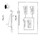
- FIG. 19 is a diagram for describing an operation of recognizing an operator by a mobile terminal.
- the mobile terminal 1 of this exemplary embodiment has almost the same configuration as those of the exemplary embodiments described above, but is different in that the input detecting part 22 has a function of changing the sensitivity of a contact input to the touch screen display device 10 in accordance with a distance from the position of the operator U to the touch screen display device 10.
- the display state is firstly changed in accordance with the distance from the position of the operator U as described above, and also, a detection sensitivity S to a contact input is set to be higher as the distance from the position of the operator U is farther.
- a dotted line shown by symbol S in Fig. 19 visually represents the height of the sensitivity S to a contact input.
- the operator U enters input at a near site on the touch screen display device 10 by pressing the touch screen with a normal pressing force, but can enter input at a farther site like the upper end of the mobile terminal 1 with a smaller pressing force, for example, by just touching softly.
- the operator 10 can obtain a visual sense as if display data is in a higher position than the display screen as the display data is positioned farther and can perform an operation, for example, press and enter input into such display data by softly touching, so that a visual sense and a sense of operation agree with each other and it is possible to increase operability.
- An information processing terminal 100 comprising:
- the display control part is configured to determine a distal position and a proximal position on the display region in a direction of the distance from the specific position to the display data, and display in a manner that a display state varies from the distal position toward the proximal position.
- the information processing terminal according to Supplementary Note 2, wherein the display control part is configured to determine the distal position and the proximal position in the direction of the distance on the display region occupied by each of a plurality of display data displayed on the touch screen display device.
- the information processing terminal according to Supplementary Note 2 or 3, wherein the display control part is configured to display in a manner that a rate of a data size of the display data decreases from the distal position toward the proximal position, or display in a manner that the rate increases from the proximal position toward the distal position.
- the information processing terminal according to any of Supplementary Notes 1 to 4, wherein the display control part is configured to change a display region occupied by shaded display data displayed in vicinity of a display region of display data displayed on the touch screen display device, in accordance with the distance.
- the information processing terminal according to any of Supplementary Notes 1 to 5, wherein the display control part is configured to change a height of a three-dimensional display displayed in vicinity of a display region of display data displayed on the touch screen display device, in accordance with the distance.
- the information processing terminal according to any of Supplementary Notes 1 to 6, wherein the display control part is configured to change density of a display color of display data displayed on the touch screen display device, in accordance with the distance.
- the information processing terminal according to any of Supplementary Notes 1 to 7, wherein the display control part is configured to change luminance of a display color of display data displayed on the touch screen display device, in accordance with the distance.
- the information processing terminal according to any of Supplementary Notes 1 to 8, wherein the display control part is configured to display in a manner that, in accordance with an angle from the specific position detected by the position detecting means to a display position of display data on the touch screen display device with respect to a display surface of the touch screen display device, a display state of the display data changes.
- the information processing terminal comprising a horizontal state detecting means for detecting that a display surface of the touch screen display device is in a horizontal state based on a previously set criterion, wherein the display control part is configured to display in a manner that the display state of the display data changes in a case where the horizontal state detecting means detects that the touch screen display device is in the horizontal state.
- a computer program comprising instructions for causing an information processing terminal including a touch screen display device to realize:
- the display control part is configured to determine a distal position and a proximal position on the display region in a direction of the distance from the specific position to the display data, and display in a manner that a display state varies from the distal position toward the proximal position.
- a display control method by an information processing terminal including a touch screen display device comprising:
- the display control method comprising determining a distal position and a proximal position on the display region in a direction of the distance from the specific position to the display data, and displaying in a manner that a display state varies from the distal position toward the proximal position.
- the programs disclosed in the exemplary embodiments and the supplementary note are stored in the storage device, or recorded on a computer-readable recording medium.
- the recording medium is a portable medium such as a flexible disk, an optical disk, a magneto-optical disk, and a semiconductor memory.
Landscapes
- Engineering & Computer Science (AREA)
- Theoretical Computer Science (AREA)
- General Engineering & Computer Science (AREA)
- Computer Hardware Design (AREA)
- Human Computer Interaction (AREA)
- Physics & Mathematics (AREA)
- General Physics & Mathematics (AREA)
- User Interface Of Digital Computer (AREA)
- Position Input By Displaying (AREA)
Abstract
Description
- The present invention relates to a mobile information processing terminal, more specifically, relates to a mobile information processing terminal that has a touch screen.
- In recent years, a mobile information processing terminal such as a mobile phone equipped with a touch screen integrally composed of a touch input device and a display device has become popular. With such a mobile information processing terminal, it is possible to display any input key on a touch screen because an input device is also a display device. For example, it is possible to detect whether the orientation of a substantially rectangular touch screen of a mobile information processing terminal is portrait or landscape and display the input key in a state that the orientation of the input key is changed depending on the orientation of the touch screen. As a related technique,
Patent Document 1 discloses a technique of imaging the face of a user of a mobile terminal to detect the orientation of the user and controlling the display orientation of a display part depending on the orientation of the user. - Patent Document 1: Japanese Unexamined Patent Application Publication No.
2007-017596 - There is a case where a mobile phone equipped with a touch screen integrally composed of a touch input device and a display device as described above is used placed horizontally on the face of a desk. In such a case, when the user operates the mobile phone from directly above the touch screen, it is easy for the user to view a key or the like displayed on the screen. However, when the user operates the mobile phone from the side, namely, from the horizontal direction to the screen, there arises a problem that it is hard for the user to view the key or the like displayed on the screen and operability degrades.
- Accordingly, an object of the present invention is to solve the abovementioned problem, degradation of the visibility and operability of an information processing terminal equipped with a touch screen display device.
- An information processing terminal as an exemplary embodiment of the present invention includes:
- a touch screen display device;
- a control device configured to control a display state on the touch screen display device; and
- a position detecting means for detecting a specific position with respect to the touch screen display device,
- Further, a program as another exemplary embodiment of the present invention is a computer program including instructions for causing an information processing terminal including a touch screen display device to realize:
- a position detecting means for detecting a specific position with respect to the touch screen display device; and
- a display control part configured to control a display state on the touch screen display device and, in accordance with a distance between a specific position detected by the position detecting means and a display region occupied by display data on the touch screen display device, change a display state of the display data.
- Further, a display control method as another exemplary embodiment of the present invention is a display control method by an information processing terminal including a touch screen display device, the display control method including:
- detecting a specific position with respect to the touch screen display device; and
- in accordance with a distance between a detected specific position and a display region occupied by display data on the touch screen display device, changing a display state of the display data on the touch screen display device.
- Configured as described above, the present invention achieves increase of the operability of an information processing terminal equipped with a touch screen display device.
-
-
Figs. 1A and 1B are diagrams showing the exterior of a mobile terminal in a first exemplary embodiment; -
Fig. 2 is a block diagram showing the configuration of the mobile terminal in the first exemplary embodiment; -
Fig. 3 is a diagram for describing an operation to recognize an operator by the mobile terminal in the first exemplary embodiment; -
Figs. 4A and 4B are diagrams for describing the operation to recognize the operator by the mobile terminal in the first exemplary embodiment; -
Figs. 5A and 5B are diagrams showing examples of display of a display screen by the mobile terminal in the first exemplary embodiment; -
Figs. 6A and 6B are diagrams showing examples of display of a display screen by the mobile terminal in the first exemplary embodiment; -
Fig. 7 is a flowchart showing an operation by the mobile terminal in the first exemplary embodiment; -
Figs. 8A and 8B are diagrams showing examples of display of a display screen by a mobile terminal in a second exemplary embodiment; -
Figs. 9A and 9B are diagrams showing examples of display of a display screen by a mobile terminal in a third exemplary embodiment; -
Figs. 10A and 10B are diagrams showing examples of display of a display screen by a mobile terminal in a fourth exemplary embodiment; -
Fig. 11 is a flowchart showing an operation by the mobile terminal in the fourth exemplary embodiment; -
Figs. 12A and 12B are diagrams showing the exterior of a mobile terminal in a fifth exemplary embodiment; -
Fig. 13 is a diagram for describing an operation to recognize an operator by the mobile terminal in the fifth exemplary embodiment; -
Figs. 14A and 14B are diagrams for describing the operation to recognize the operator by the mobile terminal in the fifth exemplary embodiment; -
Fig. 15 is a flowchart showing an operation by the mobile terminal in the fifth exemplary embodiment; -
Fig. 16 is a diagram for describing an operation to recognize an operator by a mobile terminal in a sixth exemplary embodiment; -
Figs. 17A and 17B are diagrams showing examples of display of a display screen by the mobile terminal in the sixth embodiment; -
Figs. 18A and 18B are diagrams for describing an operation to recognize an operator by a mobile terminal in a seventh exemplary embodiment; -
Fig. 19 is a diagram for describing the setting of a sensitivity to a contact input by contact on a mobile terminal in an eighth exemplary embodiment; and -
Fig. 20 is a function block diagram showing the configuration of an information processing terminal inSupplementary Note 1 of the present invention. - Referring to
Figs. 1A to 7 , a first exemplary embodiment of the present invention will be described.Figs. 1A to 2 are diagrams showing the configuration of a mobile terminal in this exemplary embodiment.Figs. 3 to 4B are diagrams for describing an operation to recognize an operator by the mobile terminal.Figs. 5A to 6B are diagrams showing examples of display of a display screen by the mobile terminal.Fig. 7 is a flowchart showing an operation by the mobile terminal. -
Figs. 1A and 1B are diagrams showing the exterior of amobile terminal 1 according to the present invention.Fig. 1A and 1B show exteriors taken from one face (a front face) and the other face (a rear face) of themobile terminal 1, respectively.Fig. 2 is a block diagram showing the circuit configuration of themobile terminal 1. - As shown in
Fig. 2 , the mobile terminal is a general information processing terminal that includes aCPU 15 as a central processing unit, and aFlash Rom 16 and aRAM 17 as storage devices storing various kinds of data. TheCPU 15 is connected with circuits and devices in the terminal via a bus as described later. TheFlash ROM 16 is a rewritable storage memory that stores various kinds of control programs executed by theCPU 15 and user data. The RAM (Random Access Memory) 17 is a working memory that stores data temporarily necessary for theCPU 15 to execute the programs. - This exemplary embodiment describes as an example a case where the
mobile terminal 1 is a mobile phone terminal such as a so-called smartphone, but themobile terminal 1 according to the present invention may be any information processing device, such as a PHS (Personal Handy-phone System), a PDA (Personal Data Assistance, Personal Digital Assistants: personal mobile information communication equipment), a tablet terminal, a personal computer, a game terminal, an electronic dictionary, and a car navigation system. - As shown in
Fig. 1A , themobile terminal 1 includes a touchscreen display device 10 on the front face. This touchscreen display device 10 includes an input device, such as an electrostatic touch screen, that accepts a contact input by an operator, and a display device such as a liquid crystal panel or an organic EL. A display face of the display device configures the input device of the touch screen. - Further, as shown in
Fig. 2 , themobile terminal 1 includes a display control part (a control device) 21 that controls a display state on the display device configuring the touchscreen display device 10. Thisdisplay control part 21, which is connected to theCPU 15, controls the display state of display data such as an icon displayed on a display screen of the touchscreen display device 10, in accordance with a position (a specific position) of the operator detected as described later. Thedisplay control part 21 is structured by installation of a program into theCPU 15, or structured by a dedicated arithmetic device. - Further, as shown in
Fig. 2 , themobile terminal 1 includes an input detecting part (a contact detecting part) 22 that detects a contact input to the input device configuring the touchscreen display device 1. Thisinput detecting part 22, which is connected to theCPU 15, detects and accepts a contact input at a display site of display data such as an icon displayed on the display screen as described later. That is, theinput detecting part 22 has a function of, when a display region such as a display area or a display range of display data changes, detecting a contact input within the display range. Theinput detecting part 22 is structured by installation of a program into theCPU 15, or structured by a dedicated arithmetic device. - Further, as shown in
Fig. 1A , themobile terminal 1 has acamera sensor part 11 that captures an image on one face, which is the face with the touchscreen display device 10 provided. Thecamera sensor part 11 is an imaging device such as a CCD image sensor or a CMOS sensor. With this, as shown inFig. 2 , themobile terminal 1 includes acamera control part 23, which is a circuit controlling thecamera sensor part 11, namely, the imaging device. Thiscamera control part 23 sends captured image data to theCPU 15, and theCPU 15 detects the position of the operator as the specific position from the data content of the image data as described later. That is, thecamera sensor part 11, thecamera control part 23, and theCPU 15 function as a position detecting means for detecting the position of the operator in cooperation with each other. Herein, when the captured image data contains a person, the position detecting means recognizes the person as the operator and detects the operator's position as the specific position. However, the position detecting means may detect another object from the image data and detect the object's position as the specific position. - Further, as shown in
Fig. 1B , themobile terminal 1 includes aproximity sensor part 12 on the other face, which is the opposite face to the face with the touchscreen display device 10 provided. Thisproximity sensor part 12, which is a sensor detecting a distance from an object, detects that themobile terminal 1 is in contact with a plane such as a board of a desk D or a wall and notifies it to theCPU 15, for example, when a distance from an object is equal to or less than a criterion value. - Furthermore, the
mobile terminal 1 includes a 3-axisacceleration sensor part 13 inside thereof. This 3-axisacceleration sensor part 13 detects acceleration of themobile terminal 1 in directions of the three axes with respect to the Earth's gravity to detect an inclination angle of themobile terminal 1 with respect to the horizontal face, and notifies it to theCPU 15. - Then, in a case where the
proximate sensor part 12 detects that themobile terminal 1 is in contact with an object and the 3-axisacceleration sensor part 13 determines that the detected inclination angle of themobile terminal 1 indicates a horizontal state, theCPU 15 detects that themobile terminal 1 is kept placed horizontally on a given board. That is, theproximity sensor part 12, the 3-axisacceleration sensor part 13, and theCPU 15 function as a horizontal state detecting means for detecting that themobile terminal 1 is in the horizontal state in cooperation with each other. - It is assumed that the horizontal state in the present invention includes a case where the inclination angle of the
mobile terminal 1 with respect to the horizontal face detected by the 3-axisacceleration sensor part 13 described above is within a previously set range (e.g., within a range of 5 degrees with respect to the horizontal face). Moreover, a condition for determining that themobile terminal 1 is in the horizontal state is not necessarily that themobile terminal 1 is placed on an object such as a board. That is, themobile terminal 1 does not necessarily include theproximity sensor part 12. Moreover, the means for detecting that themobile terminal 1 is in the horizontal state is not necessarily realized by the abovementioned configuration, and may be realized by another configuration. - Next, a detailed function of the abovementioned position detecting means configured by the
camera sensor part 11 and so on will be described. The position detecting means configured by thecamera sensor part 11, theCPU 15 and so on executes an image recognition process on image data captured by thecamera sensor part 11, and identifies which direction the operator is located in. To be specific, in this exemplary embodiment, firstly, image data of a range shown by symbol R inFigs. 3 and4B is acquired by thecamera sensor part 11 placed at the upper end part of themobile terminal 1 as shown inFig. 3 . After that, in theRAM 17, the image recognition process on the image data is executed by theCPU 15, and a process of detecting a person (a face) is executed. For example, matching with previously stored human face characteristic data or detection of a characteristic portion such as an eye or a mouth of a human by a statistical method is executed. Thus, it is detected which end side an operator U is located on of themobile terminal 1 having a substantially rectangular external shape. That is, the specific position is detected. - For example, in a case where the image data is of an image shown in the imaging range R in
Fig. 4B , because detecting the face of the operator U on the lower end side, the position detecting means detects that the operator U is located in the horizontal direction with respect to themobile terminal 1 as shown inFig. 3 and located on the lower end side inFig. 4A . In a case where the operator U is located on an end side of a specific direction within the imaging range R shown inFig. 4B , it is detected that the operator U is located on the end side and in a direction horizontal to themobile terminal 1. In a case where the operator U is located in the center of the imaging range R, it is detected that the operator U is vertically above themobile terminal 1. - The abovementioned detection of the position of the operator U is not necessarily performed by using a captured image. It may be performed by using another configuration capable of detecting a person, such as an infrared sensor. Moreover, by another configuration without using an image, the position of a detected object other than a person may be detected as the specific position.
- When it is detected that the
mobile terminal 1 is placed in the horizontal state and the operator U is located in a specific direction of the horizontal direction with respect to themobile terminal 1 as described above, thedisplay control part 21 changes the display state of the display screen of the touchscreen display device 10 and displays the display screen. To be specific, firstly, thedisplay control part 21 recognizes that the display screen is visually recognized from an end side of a specific direction of themobile terminal 1 where the operator U is located, and changes the display orientation of the display data displayed on the touchscreen display device 10 so that the end side becomes the lower side of the display screen. Then, thedisplay control part 21 further changes the display state of the display data depending on a distance from the detected position of the operator U (the specific position) to the display region occupied by the display data on the display screen of the touchscreen display device 10. To be specific, in this exemplary embodiment, as a distance from an end of a specific direction of themobile terminal 1 where the operator U is located to each display position on the display screen becomes longer, thedisplay control part 21 changes the display state of icons and the entire screen. - Examples of change of the display status of the image data displayed on the display screen by the
display control part 21 in this exemplary embodiment are shown inFigs. 5A to 6B . Firstly, in the example shown inFigs. 5A and 5B , thedisplay control part 21 controls so that, as a normal display state, a plurality ofrectangular icons 20 are displayed on the display screen of the touchscreen display device 10 as shown inFig. 5A . In this instance, it is assumed that the display data is displayed in a display orientation that the lower side of the display data faces downward inFig. 5A . When themobile terminal 1 is placed on the desk D or the like to be brought into the horizontal state from the abovementioned state and it is detected that the operator U is located horizontally and on a specific end side (the lower end side) with respect to themobile terminal 1 as shown inFig. 5B , thedisplay control part 21 firstly determines that the operator U is viewing from an arrow direction on the lower end side, and changes the display orientation of the data displayed on the touchscreen display device 10 so that the lower end side becomes the lower side of the display screen. In the example shown inFig. 5B , however, the display orientation is not changed from that inFig. 5A . Although the shape of theicons 20 is described as rectangular above, a description will be further made assuming the shape is square hereinafter. However, the shape of theicons 20 is not limited to a rectangular shape and may be any shape, for example, a circular shape. - Further, the
display control part 21 changes the display shapes of the respective square-shapedicons 20 that are the display data displayed on the display screen to trapezoidal shapes so that theicons 20 becomes larger as a distance from the specific end of themobile terminal 1 becomes longer, and displays the display screen as shown inFig. 5B . That is, thedisplay control part 21 changes the display shape of each of theicons 20 to a trapezoidal shape whose width closer to the operator U is shorter and whose width farther from the operator U is longer as compared with in the normal display state, and displays the display screen. Moreover, thedisplay control part 21 increases the display sizes of the trapezoids of theicons 20 located farther from the operator U, and displays the display screen. Consequently, theicons 20 are displayed so that the operator U can feel a stronger sense of perspective, and the operator U can visually recognize theicons 20 located farther. Although an example that thedisplay control part 21 changes the shape of theicon 20 to a trapezoidal shape in accordance with a distance between a display position of theicon 20 and the end of themobile terminal 1 is described herein, thedisplay control part 21 may change the shape to a shape similar to a parallelogram in accordance with a display position of theicon 20. - To be specific, the
display control part 21 specifies a direction of a distance from a specific end of themobile terminal 1 where the operator is located to each of theicons 20, and determines a relative position of each of theicons 20 with respect to the direction of the distance. For example, thedisplay control part 21 determines theicon 20 in the farthest position and theicon 20 in the nearest position with respect to the direction of the distance as thedistal icon 20 and theproximal icon 20, respectively. All of the icons displayed in parallel to the specific end of themobile terminal 1 may be considered to be in equal positions with respect to the direction of the distance. Then, in accordance with the relative position of each of theicons 20 with respect to the specific end, thedisplay control part 21 executes a display mode changing process on each of theicons 20. This display mode changing process is a process of, for example, performing shape change so that therespective icons 20 have trapezoidal shapes as described above and then performing size change so that the rate of the data size of each of theicons 20 becomes smaller in the proximal position than in the distal position or becomes larger in the distal position than in the proximal position. Alternatively, in the display mode changing process, thedisplay control part 21 may execute only either the shape changing process or the scaling process described above. - Change of the display state of the
icons 20 shown inFig. 5B is an example, and thedisplay control part 21 may change to another shape and display. Moreover, thedisplay control part 21 does not need to change the size of theicon 20 necessarily, and may change an image element added to theicon 20 as described in another exemplary embodiment. Furthermore, although a case of changing the shape of each of theicons 20 and displaying is illustrated above, it is also possible to change display data 20' displayed on the entire touchscreen display device 10 as shown inFig. 6A to a state as shown inFig. 6B that the width of the whole screen becomes gradually shorter toward an end side where the operator U is located and the width of the whole screen becomes gradually longer toward the opposite end side to the abovementioned end side. That is, in the same manner as described above, thedisplay control part 21 determines a distal position and a proximal position of the whole screen in a direction of a distance from a specific end of themobile terminal 1 to the screen, decreases the rate of the data size of the whole screen from the distal position to the proximal position or increases the rate from the proximal position to the distal position, and displays the display screen. - Further, as the
icons 20 are displayed with the shapes changed to trapezoidal shapes or the like as described above, theinput detecting part 22 executes a process of changing a range to detect a contact input to theicons 20. That is, theinput detecting part 22 accepts a contact input when detecting the contact input on the square-shapedicon 20 in the normal display state shown inFig. 5A , but after the display state is changed as shown inFig. 5B , detects a contact input within a shape range of the trapezoidal-shapedicon 20 and accepts the input. - The display state changing process by the
display control part 21 described above may be executed depending on the position of the operator U even when the touchscreen display device 10 of themobile terminal 1 is not located in the horizontal state. - Next, referring to a flowchart shown in
Fig. 7 , an operation of themobile terminal 1 with the abovementioned configuration will be described. First, theproximate sensor 12 placed on the rear face of themobile terminal 1 detects its distance from a proximate object. When the distance from the proximate object is equal to or less than a previously set threshold, it is determined that themobile terminal 1 is in contact with the proximate object (step S1: Yes). - Subsequently, a placement angle of the
mobile terminal 1 is detected from a value detected by the 3-axis acceleration sensor 13 included by themobile terminal 1. When the placement angle of themobile terminal 1 is within a previously set threshold with respect to an angle perpendicular to the direction of the Earth's gravity, it is determined that themobile terminal 1 is placed horizontally (step S2: Yes). - In a case where there is a contact input (a press) on the touch
screen display device 10 in a state that themobile terminal 1 is in contact with the proximate object and placed horizontally as described above (step S3: Yes), thecamera sensor part 11 placed on the front face of themobile terminal 1 is caused to operate (step S4). Then, imaging information acquired by thecamera sensor part 11 is converted into two-dimensional image data and outputted by the camera control part 23 (step S4). - After that, the image data outputted by the
camera control part 23 is sent to theRAM 17 and subjected to the image recognition process by theCPU 15, and it is thereby identified which direction of themobile terminal 1 the operator U is located in. In this instance, when it is identified that the operator U is located in the center part of the captured image data, it is determined that the operator U is vertically above themobile terminal 1. On the other hand, when it is identified that the operator U is located at an end in a specified direction of themobile terminal 1 within the image data, it is determined that the operator U is operating from a position nearly horizontal to the specific direction of the mobile terminal 1 (step S5: Yes). For example, in the example shown inFig. 4B , because the position of the operator U within the image data of the imaging range R is on the lower end side, it is identified that the position of the operator U is on the lower end side of themobile terminal 1 and, as shown inFig. 4A , is operating the horizontally placedmobile terminal 1 in the arrow direction on the horizontal plane. - Then, based on the position of the operator U identified as described above, the display state of the display screen of the touch
screen display device 10 is changed (step S6). For example, when it is identified that the operator U is located on the lower end side of themobile terminal 1 as shown by arrow inFig. 5B , the display orientation is firstly changed so that the lower end side of themobile terminal 1 becomes the lower side of the display screen. The display screen is then changed to a trapezoidal-shaped display screen that the length in the width direction on the lower side of the screen display located on the side of the operator U, namely, on the near side from the operator U is shorter and the length in the width direction on the upper side of the screen display located on the farther side from the operator U is longer, as compared with the normal display state shown inFig. 5A . Consequently, the operator can more easily view the screen display located far from him/her. - Further, along with the abovementioned image display processing, the shape of an operation area to detect a contact input on the touch
screen display device 10 is also changed to a trapezoidal shape so as to correspond to the abovementioned display area (step S7). Consequently, the operator U can perform operation corresponding to the screen display, and can operate with ease. - As described above, according to the present invention, even when the operator U views the
mobile terminal 1 from the horizontal direction in a state that themobile terminal 1 is horizontally placed on a desk or the like, the operator U can easily check the display content because the display screen is displayed with perspective strongly reflected thereon, and the operability increases. - Next, referring to
Figs. 8A and 8B , a second exemplary embodiment of the present invention will be described.Figs. 8A and 8B are diagrams showing display examples of a display screen of a mobile terminal in this exemplary embodiment. - The
mobile terminal 1 of this exemplary embodiment has almost the same configuration as that of the first exemplary embodiment described above, but a method for changing and displaying in accordance with the position of the operator U by thedisplay control part 21 is different. In this exemplary embodiment, when detecting that themobile terminal 1 is placed in the horizontal state and the operator U is located in a specific direction of the horizontal direction to themobile terminal 1 as described above, thedisplay control part 21 displays in a state that display color strength or luminance of theicons 20 or the whole screen is changed in accordance with a distance from the detected position of the operator U to a display position of display data on the display screen of the touchscreen display device 10. - For example, as compared with the normal display state described in
Fig. 5A , in the example shown inFig. 8A , when it is identified that the position of the operator U is on the lower side of the mobile terminal 1 (an arrow position), thedisplay control part 21 displays in a manner that the display strength of theicons 20 located near from the operator U is low and the display strength of theicons 20 located far from the operator U is high. Thedisplay control part 21 may change the display strength of theicons 20 so that the display strength becomes higher from the lower side to the upper side, or may change the display strength of the entire display screen of the touchscreen display device 10 so that the display strength becomes higher from the lower side to the upper side. Alternatively, contrary to the above, thedisplay control part 21 may display in a manner that the display strength on the near side from the operator U is high and the display strength on the far side from the operator U is low. - Further, the
display control part 21 may also change the luminance of the display screen in accordance with the distance from the operator U. For example, thedisplay control part 21 may display in a manner that the luminance on the near side from the operator U is low and the luminance on the far side from the operator U is high, or vice versa. - Further,
Fig. 8B shows an example of the display screen that the display strength of theicons 20 whose shapes and sizes have been changed in the first exemplary embodiment is changed in accordance with the position from the operator U as in the example shown inFig. 8A . - Also in this case, even when the operator U views the
mobile terminal 1 from the horizontal direction in a state that themobile terminal 1 is horizontally placed on a desk or the like, the operator U can easily check the display content because the display content is displayed with perspective strongly reflected thereon, and the operability increases. - Next, referring to
Figs. 9A and 9B , a third exemplary embodiment of the present invention will be described.Figs. 9A and 9B are diagrams showing display examples of a display screen of a mobile terminal in this exemplary embodiment. - The
mobile terminal 1 of this exemplary embodiment has almost the same configuration as that of the first exemplary embodiment described above, but a method for changing and displaying in accordance with the position of the operator U by thedisplay control part 21 is different. In this exemplary embodiment, when detecting that themobile terminal 1 is placed in the horizontal state and the operator U is located in a specific direction of the horizontal direction to themobile terminal 1 as described above, thedisplay control part 21 in this exemplary embodiment displays the display screen that a display region occupied by a shaded display displayed in the vicinity of a display region of each of theicons 20 or the height of a 3-dimensional display is changed in accordance with a distance from the detected position of the operator U to a display region of display data on the display screen of the touchscreen display device 10. - For example, as compared with the normal display state described in
Fig. 5A , in the example shown inFig. 9A , when it is identified that the position of the operator U is on the lower side (an arrow position) of themobile terminal 1, thedisplay control part 21 displays a small (shallow) black shaded display in the rear and on the lower side of theicon 20 located near from the operator U and a large (deep) black shaded display in the rear and on the lower side of theicon 20 located far from the operator U. Moreover,Fig. 9B shows an example that shaded displays having different sizes depending on their positions from the operator U as in the example shown inFig. 9A are displayed at theicons 20 whose shapes and sizes have been changed in the first exemplary embodiment. - To be specific, the
display control part 21 changes a display region of a shaded display as in the process of changing the display mode of theicons 20 described above. That is, thedisplay control part 21 specifies a range direction from a specific end of themobile terminal 1 to each of theicons 20, and determines a relative position of each of theicons 20 with respect to the range direction. For example, thedisplay control part 21 determines theicons 20 existing in the farthest position and the nearest position, respectively, from the specific end of themobile terminal 1 with respect to the range direction, as thedistal icon 20 and theproximal icon 20. All of the icons displayed in parallel to the specific end of themobile terminal 1 may be considered to be in equal positions with respect to the range direction. Then, thedisplay control part 21 executes a shaded display changing process on therespective icons 20 in accordance with the relative distances of therespective icons 20 from the specific end. This shaded display changing process is a process of changing the size of the shaded display, for example, decreasing the rate of the data size of the shaded display of each of theicons 20 from the distal position to the proximal position, or increasing the rate from the proximal position to the distal position so that the shaded display becomes a trapezoid in the same manner as each of theicons 20 as described above. -
Figs. 9A and 9B show a case where a shaded display is displayed on the lower side of each of theicons 20, but a 3-dimensional display that makes theicons 20 exert a 3-dimensional visual effect may be displayed instead of the shaded display. That is, in a case where themobile terminal 1 is horizontally placed and the position of the operator U with respect to theterminal 1 is identified, a 3-dimensional display displayed with a more height as the distance from the operator U becomes farther may be displayed together in the rear and on the lower side of each of theicons 20. - Also in this case, even when the operator U views the
mobile terminal 1 from the horizontal direction in a state that themobile terminal 1 is placed horizontally on a desk or the like, the operator U can easily check the display content because the display content is displayed with perspective strongly reflected thereon, and the operability increases. - Next, referring to
Figs. 10A to 11 , a fourth exemplary embodiment of the present invention will be described.Figs. 10A and 10B are diagrams showing display examples of a display screen of a mobile terminal in this exemplary embodiment, andFig. 11 is a flowchart showing an operation of the mobile terminal. - The
mobile terminal 1 of this exemplary embodiment has almost the same configuration as that of the first exemplary embodiment described above, but is different in that the position of the operator U is constantly detected and the display screen is changed and displayed as in the respective exemplary embodiments described above in accordance with the changed position of the operator U. - In the first exemplary embodiment described above, when it is detected that the
mobile terminal 1 is placed in the horizontal state (steps S1 and S2 inFig. 7 ) and a press on the touchscreen display device 10 is detected (step S3 inFig. 7 ), the camera is caused to operate to detect the position of the operator U and display control is executed (steps S4 to S7 inFig. 7 ). On the other hand, in this exemplary embodiment, when it is detected that themobile terminal 1 is placed in the horizontal state (steps S11 and S12 inFig. 11 ), the camera is caused to operate (step S13 inFig. 11 ), and it is determined whether the operator U exists within captured image data (step S14 inFig. 11 ). In this instance, for example, an image recognition process is executed on the image data and the outline and parts such as eyes, a nose and a mouth of a face existing within the image data are extracted based on a preset criterion, whereby existence of a face of a person is detected and it is determined that the operator U exists. After that, as in the first exemplary embodiment, the position of the operator U with respect to themobile terminal 1 is detected, and display control is executed depending on the position (steps S 15 to S17 inFig. 11 ). - Referring to
Figs. 10A and 10B , an example of changing the display status of display data displayed on a display screen in this exemplary embodiment will be described. First, as shown inFig. 10A , when it is detected that the operator U is located on the lower side of the mobile terminal 1 (see an arrow), the display screen is displayed in a state that the shape of each of therectangular icons 20 that are display data displayed on the display screen is changed to a trapezoidal shape that is larger as a distance from a specific end of themobile terminal 1 is longer as in the first exemplary embodiment described above. When the operator U moves to the right side of themobile terminal 1 in this state, themobile terminal 1 firstly detects that the operator U is located on the right side of themobile terminal 1 from image data constantly captured by thecamera sensor part 11. - Then, the
mobile terminal 1 determines that the operator U is viewing from the right end side of themobile terminal 1 and changes the display orientation of the display data displayed on the touchscreen display device 10 so that the right end side is the lower side of the display screen as shown by an arrow inFig. 10B . In other words, the display on the display screen shown inFig. 10A is rotated 90 degrees in the counterclockwise direction so that the display data is displayed in an orientation shown inFig. 10B . Then, also in this case, the display data is displayed in a state that the shape of each of thesquare icons 20 that are the display data displayed on the display screen is changed to a trapezoidal shape that is larger as the distance from a specific end of themobile terminal 1 is longer. The display data may be changed and displayed in accordance with the distance from the operator U in a manner as described in the respective exemplary embodiments. - Next, referring to
Figs. 12A to 15 , a fifth exemplary embodiment of the present invention will be described.Figs. 12A and 12B are diagrams showing the exterior configuration of a mobile terminal in this exemplary embodiment.Figs. 13 to 14B are diagrams for describing an operation of recognizing an operator by the mobile terminal.Fig. 15 is a flowchart showing an operation by the mobile terminal. - The
mobile terminal 1 of this exemplary embodiment has almost the same configuration as those of the exemplary embodiments described above, but is different in that acamera sensor part 11 a is placed on a side face located at a lower end of themobile terminal 1 as shown inFigs. 12A and 12B . Because thecamera sensor part 11a is thus placed on a specific side face of themobile terminal 1, the imaging range R is formed only in a direction of the specific side face of themobile terminal 1 as shown inFig. 13 , and image data as shown inFig. 14B is captured. Image data is captured as in the fourth exemplary embodiment described above in the following manner. When it is detected that themobile terminal 1 is placed in the horizontal state (steps S21 and Ss22 inFig. 15 ), the camera is caused to operate (step S23 inFig. 15 ). - After that, as in the fourth exemplary embodiment, it is determined whether the operator U exists within the captured image data (step S24 in
Fig. 15 ). In this instance, for example, an image recognition process is executed on the image data and the outline and parts such as eyes, a nose and a mouth of a face existing within the image data are extracted, whereby existence of a face of a person is detected and it is determined that the operator U exists. Consequently, it is determined that the position of the operator U is on the side of an end in the direction of the side face provided with thecamera sensor part 11a, and display control is executed depending on the position as shown inFig. 14A (steps S25, S26 inFig. 15 ). The display data may be changed and displayed in accordance with the distance from the operator U in a manner as described in the above exemplary embodiments. - Although a case of placing the
camera sensor part 11a only on the side face located at the lower end among the four side faces of themobile terminal 1 is illustrated above, thecamera sensor part 11 a may be placed on another side face. Alternatively, thecamera sensor parts 11 a may be placed on a plurality of side faces. In this case, the side face with thecamera sensor part 11a having detected the operator U placed is specified, and it is determined that the operator U is located on the side of an end of the specified side face, the display is changed in the same manner as described above. - Next, referring to
Figs. 16 to 17B , a sixth exemplary embodiment of the present invention will be described.Fig. 16 is a diagram for describing an operation of recognizing an operator by a mobile terminal.Figs. 17A and 17B are diagrams showing display examples of a display screen of the mobile terminal. - The
mobile terminal 1 of this exemplary embodiment has almost the same configuration as those of the exemplary embodiments described above, but is different in a method for changing and displaying in accordance with the position of the operator U by thedisplay control part 21. In this exemplary embodiment, when detecting that themobile terminal 1 is placed in the horizontal state and the operator U is located in a specific direction of the horizontal direction to themobile terminal 1, thedisplay control part 21 changes the display state in accordance with the distance from the position of the operator U, and also changes the display state in accordance with an angle of the operator U with respect to a display face of the touchscreen display device 10. - It is assumed that the positions of operators are those denoted by reference symbols Ua and Ub as shown in
Fig. 16 . In this case, an angle formed by a sightline La from an operator Ua to a display position of display data with the display screen is different from an angle formed by a sightline Lb from an operator Ub to the display position of the display data with the display screen. The former is an angle α, and the latter is an angle β. Since the angle of the operator Ua formed by the sightline with the display screen is smaller than that of the operator Ub, it is usual that the operator Ua is hard to visually recognize the display data. - In such a situation, the
mobile terminal 1 in this exemplary embodiment firstly extracts the outlines and parts such as eyes, noses and mouths of faces existing in image data captured by thecamera sensor part 11 based on a previously set criterion, and specifies the height positions of the faces of the respective operators Ua and Ub with respect to themobile terminal 1. In this instance, specifically, the height positions of the eyes of the operators Ua and Ub are detected. Then, the angles of the operators Ua and Ub with respect to the operation screen are specified based on the detected height positions of the operators Ua and Ub, and display control depending on the angles is executed. - For example, as shown in
Figs. 17A and 17B , for each of the operators Ua and Ub, a shaded display attached to each of theicons 20 is displayed larger as the distance from the operator is longer as described in the second exemplary embodiment, and moreover, the degree of change of the size of the shaded display is varied depending on the angles of the operators Ua and Ub. In other words, in the case of attaching a shaded display to theicon 20 displayed in the same position on the display screen, a shaded display for the operator Ua whose angle with respect to the display screen is smaller (Fig. 16A ) is displayed larger than a shaded display for the operator Ub whose angle with respect to the display screen is larger than that of the operator Ua (Fig. 16B ). Consequently, it becomes easier for the operator Ua to visually recognize the display data though the angle formed by the sightline with the display screen is small. - Although a case of changing the size of a shaded display depending on the angle is illustrated above, the size or shape of the display data may be changed as in the above exemplary embodiments, or the display color strength or the like may be changed depending on the angle of the position of the operator with respect to the display screen.
- Next, referring to
Figs. 18A and 18B , a seventh exemplary embodiment of the present invention will be described.Figs. 18A and 18B are diagrams for describing an operation of recognizing an operator by a mobile terminal. - The
mobile terminal 1 of this exemplary embodiment has almost the same configuration as those of the exemplary embodiments described above, but is characterized by a function of specifying the position of a previously set specific operator U from image data captured by thecamera sensor part 11. - For example, in a case where the operator U is located on the lower end side of the
mobile terminal 1 and another operator U' is located on the left end side as shown by arrows U and U' inFig. 18A , the two operators U and U' exist within the image data captured by thecamera sensor part 11 as shown inFig. 18B . In such a case, the mobile terminal 1 (the position detecting means) specifies the one operator U. For example, themobile terminal 1 extracts the outlines and parts such as eyes, noses and mouths of all faces existing in the image data based on a previously set criterion, and specifies an operator whose specific part or outline of the face is the largest. After that, as shown inFig. 18A , display of theicons 20 is changed in accordance with the position of the specified operator U. - Although a rule for specifying the one operator U within the image data is previously set, the operator U may be specified based on another rule. For example, the position of an operator existing in the image data last in a preset time period may be specified, or the position of a specific operator whose face characteristic data is previously stored may be specified. Alternatively, the
mobile terminal 1 may detect an operation like blink of an operator existing in the image data and specify the position of the operator having performed the operation. - Next, referring to
Fig. 19 , an eighth exemplary embodiment of the present invention will be described.Fig. 19 is a diagram for describing an operation of recognizing an operator by a mobile terminal. - The
mobile terminal 1 of this exemplary embodiment has almost the same configuration as those of the exemplary embodiments described above, but is different in that theinput detecting part 22 has a function of changing the sensitivity of a contact input to the touchscreen display device 10 in accordance with a distance from the position of the operator U to the touchscreen display device 10. - For example, in a case where it is detected that the operator U is located on the lower end side of the mobile terminal 1 (see an arrow) as shown in
Fig. 19 , the display state is firstly changed in accordance with the distance from the position of the operator U as described above, and also, a detection sensitivity S to a contact input is set to be higher as the distance from the position of the operator U is farther. A dotted line shown by symbol S inFig. 19 visually represents the height of the sensitivity S to a contact input. - Consequently, for example, the operator U enters input at a near site on the touch
screen display device 10 by pressing the touch screen with a normal pressing force, but can enter input at a farther site like the upper end of themobile terminal 1 with a smaller pressing force, for example, by just touching softly. - In the case of displaying a shaded display more largely or displaying a 3-dimensional display with a more height as a distance from the position of the operator U to the
icons 20 displayed on the touchscreen display device 10 becomes farther as described in the third exemplary embodiment, it is favorable to set so that the detection sensitivity S to a contact input becomes higher as the distance from the position of the operator U becomes farther as described above. Consequently, theoperator 10 can obtain a visual sense as if display data is in a higher position than the display screen as the display data is positioned farther and can perform an operation, for example, press and enter input into such display data by softly touching, so that a visual sense and a sense of operation agree with each other and it is possible to increase operability. - <Supplementary Notes>
- The whole or part of the exemplary embodiments disclosed above can be described as the following supplementary notes. The outline of configurations of an information processing terminal (see
Fig. 20 ), a program, and a display control method according to the present invention will be described below. However, the present invention will not be limited to the following configurations. - An
information processing terminal 100, comprising: - a touch
screen display device 110; - a
control device 120 configured to control a display state on the touchscreen display device 110; and - a position detecting means 130 for detecting a specific position with respect to the touch
screen display device 110, - wherein the
control device 120 includes adisplay control part 121 configured to, in accordance with a distance between a specific position detected by the position detecting means 130 and a display region occupied by display data on the touchscreen display device 110, change a display state of the display data. - The information processing terminal according to
Supplementary Note 1, wherein the display control part is configured to determine a distal position and a proximal position on the display region in a direction of the distance from the specific position to the display data, and display in a manner that a display state varies from the distal position toward the proximal position. - The information processing terminal according to Supplementary Note 2, wherein the display control part is configured to determine the distal position and the proximal position in the direction of the distance on the display region occupied by each of a plurality of display data displayed on the touch screen display device.
- The information processing terminal according to
Supplementary Note 2 or 3, wherein the display control part is configured to display in a manner that a rate of a data size of the display data decreases from the distal position toward the proximal position, or display in a manner that the rate increases from the proximal position toward the distal position. - The information processing terminal according to any of
Supplementary Notes 1 to 4, wherein the display control part is configured to change a display region occupied by shaded display data displayed in vicinity of a display region of display data displayed on the touch screen display device, in accordance with the distance. - The information processing terminal according to any of
Supplementary Notes 1 to 5, wherein the display control part is configured to change a height of a three-dimensional display displayed in vicinity of a display region of display data displayed on the touch screen display device, in accordance with the distance. - The information processing terminal according to any of
Supplementary Notes 1 to 6, wherein the display control part is configured to change density of a display color of display data displayed on the touch screen display device, in accordance with the distance. - The information processing terminal according to any of
Supplementary Notes 1 to 7, wherein the display control part is configured to change luminance of a display color of display data displayed on the touch screen display device, in accordance with the distance. - The information processing terminal according to any of
Supplementary Notes 1 to 8, wherein the display control part is configured to display in a manner that, in accordance with an angle from the specific position detected by the position detecting means to a display position of display data on the touch screen display device with respect to a display surface of the touch screen display device, a display state of the display data changes. - The information processing terminal according to any of
Supplementary Notes 1 to 9, wherein: - the control device includes a contact detecting part configured to detect a contact input to the touch screen display device; and
- the contact detecting part is configured to change a range to detect a contact input to display data in accordance with change of the display state of the display data by the display control part.
- The information processing terminal according to any of
Supplementary Notes 1 to 10, wherein: - the control device includes a contact detecting part configured to detect a contact input to the touch screen display device; and
- the contact detecting part is configured to change detection sensitivity to a contact input to the touch screen display device in accordance with a distance between the specific position detected by the position detecting means and a display position of display data on the touch screen display device.
- The information processing terminal according to any of
Supplementary Notes 1 to 11, comprising a horizontal state detecting means for detecting that a display surface of the touch screen display device is in a horizontal state based on a previously set criterion,
wherein the display control part is configured to display in a manner that the display state of the display data changes in a case where the horizontal state detecting means detects that the touch screen display device is in the horizontal state. - The information processing terminal according to any of
Supplementary Notes 1 to 12, wherein: - the position detecting means is configured to detect a previously set specific person existing in the specific position; and
- the display control part is configured to, in accordance with a distance between the position of the specific person detected by the position detecting means and a display position of display data on the touch screen display device, change a display state of the display data.
- A computer program comprising instructions for causing an information processing terminal including a touch screen display device to realize:
- a position detecting means for detecting a specific position with respect to the touch screen display device; and
- a display control part configured to control a display state on the touch screen display device and, in accordance with a distance between a specific position detected by the position detecting means and a display region occupied by display data on the touch screen display device, change a display state of the display data.
- The computer program according to
Supplementary Note 14, wherein the display control part is configured to determine a distal position and a proximal position on the display region in a direction of the distance from the specific position to the display data, and display in a manner that a display state varies from the distal position toward the proximal position. - A display control method by an information processing terminal including a touch screen display device, the display control method comprising:
- detecting a specific position with respect to the touch screen display device; and
- in accordance with a distance between a detected specific position and a display region occupied by display data on the touch screen display device, changing a display state of the display data on the touch screen display device.
- The display control method according to
Supplementary Note 16, comprising determining a distal position and a proximal position on the display region in a direction of the distance from the specific position to the display data, and displaying in a manner that a display state varies from the distal position toward the proximal position. - The programs disclosed in the exemplary embodiments and the supplementary note are stored in the storage device, or recorded on a computer-readable recording medium. For example, the recording medium is a portable medium such as a flexible disk, an optical disk, a magneto-optical disk, and a semiconductor memory.
- Although the present invention is described above by referring to the above exemplary embodiments, the present invention is not limited to the exemplary embodiments described above. The configurations and details of the present invention can be modified in various manners that can be understood by one skilled in the art within the scope of the present invention.
- The present invention is based upon and claims the benefit of priority from Japanese patent application No.
2011-208567, filed on September 26, 2011 -
- 1
- mobile terminal
- 10
- touch screen display device
- 11
- camera sensor part
- 12
- proximity sensor part
- 13
- 3-axis acceleration sensor
- 21
- display control part
- 22
- input detecting part
- 23
- camera control part
- 100
- information processing terminal
- 110
- touch screen display device
- 120
- control device
- 121
- display control part
- 130
- position detecting means
Claims (17)
- An information processing terminal comprising:a touch screen display device;a control device configured to control a display state on the touch screen display device; anda position detecting means for detecting a specific position with respect to the touch screen display device,wherein the control device includes a display control part configured to, in accordance with a distance between a specific position detected by the position detecting means and a display region occupied by display data on the touch screen display device, change a display state of the display data.
- The information processing terminal according to Claim 1, wherein the display control part is configured to determine a distal position and a proximal position on the display region in a direction of the distance from the specific position to the display data, and display in a manner that a display state varies from the distal position toward the proximal position.
- The information processing terminal according to Claim 2, wherein the display control part is configured to determine the distal position and the proximal position in the direction of the distance on the display region occupied by each of a plurality of display data displayed on the touch screen display device.
- The information processing terminal according to Claim 2 or 3, wherein the display control part is configured to display in a manner that a rate of a data size of the display data decreases from the distal position toward the proximal position, or display in a manner that the rate increases from the proximal position toward the distal position.
- The information processing terminal according to any of Claims 1 to 4, wherein the display control part is configured to change a display region occupied by shaded display data displayed in vicinity of a display region of display data displayed on the touch screen display device, in accordance with the distance.
- The information processing terminal according to any of Claims 1 to 5, wherein the display control part is configured to change a height of a three-dimensional display displayed in vicinity of a display region of display data displayed on the touch screen display device, in accordance with the distance.
- The information processing terminal according to any of Claims 1 to 6, wherein the display control part is configured to change density of a display color of display data displayed on the touch screen display device, in accordance with the distance.
- The information processing terminal according to any of Claims 1 to 7, wherein the display control part is configured to change luminance of a display color of display data displayed on the touch screen display device, in accordance with the distance.
- The information processing terminal according to any of Claims 1 to 8, wherein the display control part is configured to display in a manner that, in accordance with an angle from the specific position detected by the position detecting means to a display position of display data on the touch screen display device with respect to a display surface of the touch screen display device, a display state of the display data changes.
- The information processing terminal according to any of Claims 1 to 9, wherein:the control device includes a contact detecting part configured to detect a contact input to the touch screen display device; andthe contact detecting part is configured to change a range to detect a contact input to display data in accordance with change of the display state of the display data by the display control part.
- The information processing terminal according to any of Claims 1 to 10, wherein:the control device includes a contact detecting part configured to detect a contact input to the touch screen display device; andthe contact detecting part is configured to change detection sensitivity to a contact input to the touch screen display device in accordance with a distance between the specific position detected by the position detecting means and a display position of display data on the touch screen display device.
- The information processing terminal according to any of Claims 1 to 11, comprising a horizontal state detecting means for detecting that a display surface of the touch screen display device is in a horizontal state based on a previously set criterion,
wherein the display control part is configured to display in a manner that the display state of the display data changes in a case where the horizontal state detecting means detects that the touch screen display device is in the horizontal state. - The information processing terminal according to any of Claims 1 to 12, wherein:the position detecting means is configured to detect a previously set specific person existing in the specific position; andthe display control part is configured to, in accordance with a distance between the position of the specific person detected by the position detecting means and a display position of display data on the touch screen display device, change a display state of the display data.
- A computer program comprising instructions for causing an information processing terminal including a touch screen display device to realize:a position detecting means for detecting a specific position with respect to the touch screen display device; anda display control part configured to control a display state on the touch screen display device and, in accordance with a distance between a specific position detected by the position detecting means and a display region occupied by display data on the touch screen display device, change a display state of the display data.
- The computer program according to Claim 14, wherein the display control part is configured to determine a distal position and a proximal position on the display region in a direction of the distance from the specific position to the display data, and display in a manner that a display state varies from the distal position toward the proximal position.
- A display control method by an information processing terminal including a touch screen display device, the display control method comprising:detecting a specific position with respect to the touch screen display device; andin accordance with a distance between a detected specific position and a display region occupied by display data on the touch screen display device, changing a display state of the display data on the touch screen display device.
- The display control method according to Claim 16, comprising determining a distal position and a proximal position on the display region in a direction of the distance from the specific position to the display data, and displaying in a manner that a display state varies from the distal position toward the proximal position.
Applications Claiming Priority (2)
| Application Number | Priority Date | Filing Date | Title |
|---|---|---|---|
| JP2011208567 | 2011-09-26 | ||
| PCT/JP2012/005929 WO2013046596A1 (en) | 2011-09-26 | 2012-09-18 | Mobile information processing terminal |
Publications (2)
| Publication Number | Publication Date |
|---|---|
| EP2763010A1 true EP2763010A1 (en) | 2014-08-06 |
| EP2763010A4 EP2763010A4 (en) | 2015-06-03 |
Family
ID=47994682
Family Applications (1)
| Application Number | Title | Priority Date | Filing Date |
|---|---|---|---|
| EP12835441.2A Withdrawn EP2763010A4 (en) | 2011-09-26 | 2012-09-18 | Mobile information processing terminal |
Country Status (4)
| Country | Link |
|---|---|
| US (1) | US20140300570A1 (en) |
| EP (1) | EP2763010A4 (en) |
| JP (1) | JPWO2013046596A1 (en) |
| WO (1) | WO2013046596A1 (en) |
Cited By (1)
| Publication number | Priority date | Publication date | Assignee | Title |
|---|---|---|---|---|
| CN106648413A (en) * | 2016-09-28 | 2017-05-10 | 北京小米移动软件有限公司 | Method and device for processing operable region based on mobile phone |
Families Citing this family (11)
| Publication number | Priority date | Publication date | Assignee | Title |
|---|---|---|---|---|
| WO2013082695A1 (en) * | 2011-12-08 | 2013-06-13 | Exopc | Method for improving an interaction with a user interface displayed on a 3d touch screen display |
| CN102945520A (en) * | 2012-11-02 | 2013-02-27 | 中兴通讯股份有限公司 | Equipment management system and method |
| JP6113616B2 (en) * | 2013-09-20 | 2017-04-12 | シャープ株式会社 | Mobile terminal and control method |
| JPWO2015151387A1 (en) * | 2014-04-04 | 2017-04-13 | ソニー株式会社 | Image processing apparatus, image processing method, and program |
| JP6133245B2 (en) * | 2014-08-07 | 2017-05-24 | 本田技研工業株式会社 | Vehicles equipped with electronic devices |
| JP6548956B2 (en) * | 2015-05-28 | 2019-07-24 | 株式会社コロプラ | SYSTEM, METHOD, AND PROGRAM |
| JP6406176B2 (en) * | 2015-08-31 | 2018-10-17 | 京セラドキュメントソリューションズ株式会社 | Display device and display control program |
| US10254918B2 (en) * | 2015-08-27 | 2019-04-09 | Kyocera Document Solutions Inc. | Tilt adjustable perspective icons display device and non-transitory computer readable medium |
| JP6418108B2 (en) * | 2015-08-31 | 2018-11-07 | 京セラドキュメントソリューションズ株式会社 | Display device and display control program |
| JP6344337B2 (en) * | 2015-08-27 | 2018-06-20 | 京セラドキュメントソリューションズ株式会社 | Display device and display control program |
| JP7050067B2 (en) * | 2016-12-14 | 2022-04-07 | サムスン エレクトロニクス カンパニー リミテッド | Display device and its control method |
Family Cites Families (21)
| Publication number | Priority date | Publication date | Assignee | Title |
|---|---|---|---|---|
| JP3658537B2 (en) * | 2000-06-27 | 2005-06-08 | シャープ株式会社 | Information recording and display device |
| JP2007017596A (en) | 2005-07-06 | 2007-01-25 | Matsushita Electric Ind Co Ltd | Mobile terminal device |
| US8736557B2 (en) * | 2006-09-11 | 2014-05-27 | Apple Inc. | Electronic device with image based browsers |
| US20100007602A1 (en) * | 2006-10-02 | 2010-01-14 | Pioneer Corporation | Image display device |
| US8462109B2 (en) * | 2007-01-05 | 2013-06-11 | Invensense, Inc. | Controlling and accessing content using motion processing on mobile devices |
| JP4557058B2 (en) * | 2007-12-07 | 2010-10-06 | ソニー株式会社 | Information display terminal, information display method, and program |
| US20090156970A1 (en) * | 2007-12-14 | 2009-06-18 | Sullivan Shannon E | System and method for exercising eyes |
| KR101495164B1 (en) * | 2008-04-10 | 2015-02-24 | 엘지전자 주식회사 | Mobile terminal and its screen processing method |
| JP2010004118A (en) * | 2008-06-18 | 2010-01-07 | Olympus Corp | Digital photograph frame, information processing system, control method, program, and information storage medium |
| US9204050B2 (en) * | 2008-12-25 | 2015-12-01 | Panasonic Intellectual Property Management Co., Ltd. | Information displaying apparatus and information displaying method |
| JP5374170B2 (en) * | 2009-01-22 | 2013-12-25 | 任天堂株式会社 | Information processing program, information processing apparatus, information processing system, and information processing method |
| US8179449B2 (en) * | 2009-05-20 | 2012-05-15 | Sony Ericsson Mobile Communications Ab | Portable electronic apparatus including a display and method for controlling display content based on movement of the display and user position |
| US8373669B2 (en) * | 2009-07-21 | 2013-02-12 | Cisco Technology, Inc. | Gradual proximity touch screen |
| KR20110052998A (en) * | 2009-11-13 | 2011-05-19 | 삼성전자주식회사 | Method and apparatus for providing a user interface in a device |
| US8922592B2 (en) * | 2009-11-30 | 2014-12-30 | Pioneer Corporation | Map display device, map display method, map display program, and computer-readable recording medium |
| JP4900741B2 (en) * | 2010-01-29 | 2012-03-21 | 島根県 | Image recognition apparatus, operation determination method, and program |
| KR20110101585A (en) * | 2010-03-09 | 2011-09-16 | 삼성전자주식회사 | Screen switching device and method of a portable terminal |
| JP2011223556A (en) * | 2010-03-25 | 2011-11-04 | Kyocera Corp | Portable terminal device |
| JP5573379B2 (en) * | 2010-06-07 | 2014-08-20 | ソニー株式会社 | Information display device and display image control method |
| JP2012038164A (en) * | 2010-08-09 | 2012-02-23 | Sony Corp | Information processing unit |
| JP5732784B2 (en) * | 2010-09-07 | 2015-06-10 | ソニー株式会社 | Information processing apparatus, information processing method, and computer program |
-
2012
- 2012-09-18 JP JP2013535877A patent/JPWO2013046596A1/en active Pending
- 2012-09-18 WO PCT/JP2012/005929 patent/WO2013046596A1/en not_active Ceased
- 2012-09-18 US US14/347,186 patent/US20140300570A1/en not_active Abandoned
- 2012-09-18 EP EP12835441.2A patent/EP2763010A4/en not_active Withdrawn
Cited By (2)
| Publication number | Priority date | Publication date | Assignee | Title |
|---|---|---|---|---|
| CN106648413A (en) * | 2016-09-28 | 2017-05-10 | 北京小米移动软件有限公司 | Method and device for processing operable region based on mobile phone |
| CN106648413B (en) * | 2016-09-28 | 2020-07-28 | 北京小米移动软件有限公司 | Method and device for processing an operable area based on a mobile phone |
Also Published As
| Publication number | Publication date |
|---|---|
| WO2013046596A1 (en) | 2013-04-04 |
| US20140300570A1 (en) | 2014-10-09 |
| JPWO2013046596A1 (en) | 2015-03-26 |
| EP2763010A4 (en) | 2015-06-03 |
Similar Documents
| Publication | Publication Date | Title |
|---|---|---|
| US20140300570A1 (en) | Mobile information processing terminal | |
| KR102121592B1 (en) | Method and apparatus for protecting eyesight | |
| US9007321B2 (en) | Method and apparatus for enlarging a display area | |
| CN105210144B (en) | Display control device, display control method, and recording medium | |
| JP5433935B2 (en) | Screen display control method, screen display control method, electronic device, and program | |
| US9411415B2 (en) | Method and apparatus for displaying data | |
| US20160292922A1 (en) | Display control device, display control method, and recording medium | |
| EP3923239B1 (en) | Distance measurement method and electronic device | |
| EP2950180B1 (en) | Method for determining screen display mode and terminal device | |
| ES3061081T3 (en) | Image display method and mobile terminal | |
| CN104238739A (en) | Visibility improvement method based on eye tracking and electronic device | |
| KR20140096861A (en) | Mobile device and method for operating the same | |
| US20210055821A1 (en) | Touchscreen Device and Method Thereof | |
| WO2014097653A1 (en) | Electronic apparatus, control method, and program | |
| CN107168632B (en) | Processing method of user interface of electronic equipment and electronic equipment | |
| JP2013150129A (en) | Portable terminal | |
| EP3690605A1 (en) | Gesture recognition method and electronic device | |
| CN108830186A (en) | Method for extracting content, device, equipment and the storage medium of text image | |
| CN102736846B (en) | Detection area enlarging device, display device, and detection area enlarging method | |
| CN110795019A (en) | Key identification method and device of soft keyboard and storage medium | |
| JP6046384B2 (en) | Terminal device | |
| US20170160875A1 (en) | Electronic apparatus having a sensing unit to input a user command adn a method thereof | |
| JP5223784B2 (en) | Mobile terminal device | |
| JP5670255B2 (en) | Display device | |
| JP5796052B2 (en) | Screen display control method, screen display control method, electronic device, and program |
Legal Events
| Date | Code | Title | Description |
|---|---|---|---|
| PUAI | Public reference made under article 153(3) epc to a published international application that has entered the european phase |
Free format text: ORIGINAL CODE: 0009012 |
|
| 17P | Request for examination filed |
Effective date: 20140328 |
|
| AK | Designated contracting states |
Kind code of ref document: A1 Designated state(s): AL AT BE BG CH CY CZ DE DK EE ES FI FR GB GR HR HU IE IS IT LI LT LU LV MC MK MT NL NO PL PT RO RS SE SI SK SM TR |
|
| DAX | Request for extension of the european patent (deleted) | ||
| RA4 | Supplementary search report drawn up and despatched (corrected) |
Effective date: 20150507 |
|
| RIC1 | Information provided on ipc code assigned before grant |
Ipc: G06F 3/01 20060101ALI20150429BHEP Ipc: G06F 3/041 20060101ALI20150429BHEP Ipc: G06F 1/16 20060101ALI20150429BHEP Ipc: G06F 3/048 20130101AFI20150429BHEP |
|
| RAP1 | Party data changed (applicant data changed or rights of an application transferred) |
Owner name: NEC CORPORATION |
|
| STAA | Information on the status of an ep patent application or granted ep patent |
Free format text: STATUS: THE APPLICATION HAS BEEN WITHDRAWN |
|
| 18W | Application withdrawn |
Effective date: 20180227 |