EP2763002A2 - Pen-type input device and electronic information board system - Google Patents
Pen-type input device and electronic information board system Download PDFInfo
- Publication number
- EP2763002A2 EP2763002A2 EP14153795.1A EP14153795A EP2763002A2 EP 2763002 A2 EP2763002 A2 EP 2763002A2 EP 14153795 A EP14153795 A EP 14153795A EP 2763002 A2 EP2763002 A2 EP 2763002A2
- Authority
- EP
- European Patent Office
- Prior art keywords
- penpoint
- pen
- input device
- type input
- end portion
- Prior art date
- Legal status (The legal status is an assumption and is not a legal conclusion. Google has not performed a legal analysis and makes no representation as to the accuracy of the status listed.)
- Withdrawn
Links
Images



Classifications
-
- G—PHYSICS
- G06—COMPUTING OR CALCULATING; COUNTING
- G06F—ELECTRIC DIGITAL DATA PROCESSING
- G06F3/00—Input arrangements for transferring data to be processed into a form capable of being handled by the computer; Output arrangements for transferring data from processing unit to output unit, e.g. interface arrangements
- G06F3/01—Input arrangements or combined input and output arrangements for interaction between user and computer
- G06F3/03—Arrangements for converting the position or the displacement of a member into a coded form
- G06F3/033—Pointing devices displaced or positioned by the user, e.g. mice, trackballs, pens or joysticks; Accessories therefor
- G06F3/0354—Pointing devices displaced or positioned by the user, e.g. mice, trackballs, pens or joysticks; Accessories therefor with detection of two-dimensional [2D] relative movements between the device, or an operating part thereof, and a plane or surface, e.g. 2D mice, trackballs, pens or pucks
- G06F3/03545—Pens or stylus
-
- G—PHYSICS
- G06—COMPUTING OR CALCULATING; COUNTING
- G06F—ELECTRIC DIGITAL DATA PROCESSING
- G06F3/00—Input arrangements for transferring data to be processed into a form capable of being handled by the computer; Output arrangements for transferring data from processing unit to output unit, e.g. interface arrangements
- G06F3/01—Input arrangements or combined input and output arrangements for interaction between user and computer
- G06F3/03—Arrangements for converting the position or the displacement of a member into a coded form
- G06F3/041—Digitisers, e.g. for touch screens or touch pads, characterised by the transducing means
-
- G—PHYSICS
- G06—COMPUTING OR CALCULATING; COUNTING
- G06F—ELECTRIC DIGITAL DATA PROCESSING
- G06F3/00—Input arrangements for transferring data to be processed into a form capable of being handled by the computer; Output arrangements for transferring data from processing unit to output unit, e.g. interface arrangements
- G06F3/01—Input arrangements or combined input and output arrangements for interaction between user and computer
- G06F3/03—Arrangements for converting the position or the displacement of a member into a coded form
- G06F3/041—Digitisers, e.g. for touch screens or touch pads, characterised by the transducing means
- G06F3/042—Digitisers, e.g. for touch screens or touch pads, characterised by the transducing means by opto-electronic means
- G06F3/0421—Digitisers, e.g. for touch screens or touch pads, characterised by the transducing means by opto-electronic means by interrupting or reflecting a light beam, e.g. optical touch-screen
Definitions
- the present invention relates to a pen-type input device and electronic information board system.
- one type of the electronic information board includes an image display device having a large screen (the diagonal dimension is, for example, 40 inches to 60 inches) using a flat panel such as a liquid crystal panel or a plasma panel, a coordinate detection device (a touch panel) which detects the coordinate of a position where a display face is touched, and a control device which causes various images (images containing a character, a number, or a figure) written on the display face of the image display device to be displayed based on coordinate data output from the coordinate detection device.
- a coordinate detection device a touch panel
- the system of this electronic information board has a function of superposing a graphic of a handwritten character written by a pen-type input device (an object to be detected) on an image displayed on a display face by causing the pen-type input device to touch a touch panel and a function of taking a screen of a personal computer into and superposing and drawing graphics written by the pen-type input device on the screen.
- Patent Document 2 discloses a pen-type input device including a writing unit which transmits a transcription detecting signal by detecting a transcribing operation when a penpoint made of, for example, an elastic member is moved while the penpoint touches a touch panel.
- the pen-type input device In a case where the pen-type input device is used to write on an electronic information board, the pen-type input device is moved so as to go along a display surface of the electronic information board while the penpoint touches the display surface of the electronic information board, and therefore the coordinate of the position where the penpoint touches the display surface is detected by an optical sensor and characters and graphic symbols can be written like an ordinary blackboard or whiteboards.
- the penpoint is made of a material having elasticity and the front end recess of the pen-type input device includes a detection switch for detecting a displacement caused by pressure received by the penpoint from the contacting display unit in order to improve a write feeling at a time of a contact of the penpoint with the display face of the electronic information board. Then, the electronic information board displays the characters and the graphic symbols which are written on the display face based on information of the contact position of the pen-type input device which touches the display face and a signal transmitted from the detection switch of the pen-type input device.
- a contact pressure (a compression load) is applied onto the penpoint against the display face. Therefore, the penpoint is compressed by pressure in an axial direction so that an outer peripheral side of the penpoint expands in a radius direction. After repeated applications of the contact pressure onto the penpoint, the shape of the penpoint gradually deforms and finally the outer peripheral side of the penpoint may not return from the expanded state. After the penpoint is deformed onto the outer peripheral side as described above, the deformed part of the penpoint contacts the inner wall of the front end recess of the pen-type input device. Then, a write switch cannot be normally operated. Thus, there occurs a problem that a writing operation using the pen-type input device cannot be recognized.
- embodiments of the present invention provides a novel and useful pen-type input device and an electronic information board system solving one or more of the problems discussed above.
- One aspect of the embodiments of the present invention may be to provide a pen-type input device including a body shaped like a pen; a penpoint movable portion inserted into a front end recess included in the body; and a transmission part which transmits a transcription detecting signal of a contact position when the penpoint movable portion is caused to touch a display face of an electronic information board, wherein the penpoint movable portion includes a penpoint member, which is made of an elastic member and includes a front end portion caused to touch the display face, and a penpoint holding portion, which has a rigidity higher than that of the penpoint member, fits around an outer periphery of a base end portion of the penpoint member, and holds the penpoint member so as to prevent deformation of the outer periphery of the base end portion of the penpoint member.
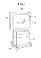
- FIG. 1 is a perspective view illustrating an electronic information board system to which a pen-type device of an embodiment of the present invention is applied.
- the electronic information board system 10 includes a display unit 20, a stand 40, and a device accommodating portion 50.
- the display unit 20 is formed by a flat panel such as a liquid crystal panel or a plasma panel.
- a display face 22 and a touch panel (a coordinate detecting part) 24 are formed on a front surface of the display unit 20.
- a penpoint of a pen-type input device 100 which is dedicated for the electronic information board system 10, can write characters, graphic symbols, or the like onto the display face of the electronic information board system 10.
- the pen-type input device 100 transmits a transcription detecting signal as a wireless signal when the penpoint at one end of the pen-type input device 100 touches the display face 22.
- the display unit 20 displays characters, graphic symbols, or the like, which are written at a coordinate position detected by the touch panel 24, when the transcription detecting signal transmitted from the pen-type input device 100 is received by the display unit 20.
- an erasure detecting signal is transmitted as a wireless signal.
- the display unit 20 erases characters, graphic symbols, or the like, which are written at a coordinate position detected by the touch panel 24, when the erasure detecting signal transmitted from the pen-type input device 100 is received by the display unit 20.
- the same color e.g., white
- the color of a background on the screen is given to the detected coordinate position by a controller 60.
- the device accommodating portion 50 accommodates various devices such as a controller, a printer, or a video disk device. Further, a keyboard 30 for performing an input operation is mounted on the upper surface of the device accommodating portion 50.
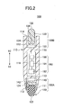
- FIG. 2 is a longitudinal cross-sectional view of the pen-type input device of the embodiment.
- the pen-type input device 100 includes a pen body 110 in a cylindrical shape, a writing unit 100A provided at one end of the pen body 110, and an erasure unit 100B provided at the other end of the pen body 110.
- the pen body 110 has a front end recess 112, in which a penpoint movable portion 120 and a penpoint detection switch 140 are accommodated.
- the erasure unit 100B includes a back end recess 114 in the pen body 110, and a pen tail movable portion 130 and a pen tail detection switch 150, which are accommodated inside the back end recess 114.
- the penpoint detection switch 140 and the pen tail detection switch 150 may be a so-called push switch having movable pieces 142 and 152 protruding in axial directions, respectively.
- the movable piece 142 is separated from the penpoint movable portion 120 interposing a small gap between the movable piece 142 and the penpoint movable portion 120.
- the movable piece 152 is separated from the pen tail movable portion 130 interposing a small gap between the movable piece 152 and the pen tail movable portion 130.
- the movable piece 142 and 152 are pressed when the penpoint movable portion 120 and the pen tail movable portion 130 move in the axial direction by a distance equal to or greater than a predetermined distance (equal to or greater than the small gap), respectively.
- the penpoint detection switch 140 and the pen tail detection switch 150 are switched from off to on to thereby output a detection signal from the pen-type input device.
- One end of the penpoint detection switch 140 is fixed to a partition wall 113 formed in a bottom of the front end recess 112.
- One end of the pen tail detection switch 150 is fixed to a partition wall 115 formed in a bottom of the back end recess 114.
- a spring member pressing the movable piece 142 onto a position of switching off the penpoint detection switch 140 is integrated in the penpoint detection switch 140
- a spring member pressing the movable piece 152 onto a position of switching off the pen tail detection switch 150 is integrated in the pen tail detection switch 150.
- a transmission circuit unit (a transmission part) 180 is accommodated in an internal space 116 of the pen body 110.
- the transmission circuit unit 180 includes a signal input portion 182, a signal processing portion 184, and a detection signal transmitting portion 186.
- Detection signals from the penpoint detection switch 140 and the pen tail detection switch 150 are input into the signal input portion 182.
- the signal processing portion 184 converts the detection signal input through the signal input portion 182 into a wireless signal.
- the detection signal transmitting portion 186 transmits the wireless signal (infrared rays) generated by the signal processing portion 184.
- infrared rays are used as the wireless signal within the embodiment, the wireless signal is not limited to the infrared rays and may be a signal of electromagnetic wave, light, or sound wave.
- FIG. 3B is a longitudinal cross-sectional view of the penpoint structure of the pen-type input device.
- the penpoint movable portion 120 is inserted into the front end recess 112 provided in the front end 111 of the pen body 111 so as to be slidably moved in the axial direction (a direction of X1-X2).
- the penpoint movable portion 120 includes a penpoint member 122 made of an elastic member and a penpoint holding portion 124 into which an outer periphery of the base end portion 122a of the penpoint member 122 is fit.
- a front end portion 112b of the penpoint member 122 is shaped like a curved surface (a hemisphere face), and the outer periphery of the base end portion 122a of the penpoint member 122 is shaped like a cylindrical column and extends in the direction of X1-X2. Said differently, the penpoint member 122 is shaped like a rod having no step on the outer periphery of the penpoint member 122. Even if an impact is applied after dropping the pen-type input device 100, the penpoint member 122 having improved impact resistance is not broken.
- the penpoint member 122 may be tapered to have a gradient such that an outer diameter of the penpoint member 122 on the front end side is smaller than an outer diameter of the penpoint member 122 on the side of the base end portion 122a.
- the angle of the gradient of a tapered surface relative to the axis (the central line) of the penpoint member 122 may be equal to or less than about 5 °, for example, so that the penpoint member 122, which is fit into the penpoint holding portion 124, can be fixed by a bond.
- the penpoint holding portion 124 includes an engaging recess into which the outer periphery of the base end portion 122a of the penpoint member 122 fits, and a pressing portion 122b of the penpoint member 122 which contacts the movable piece 142 of the penpoint detection switch 140 during the transcribing operation.
- the engaging recess 124a is formed inside the wall portion 124d in the cylindrical shape so as to cover the entire periphery of the base end portion of the penpoint member 122.
- the elasticity modulus of the penpoint holding portion 124 is higher than the elasticity modulus of the penpoint member 122. Therefore, when the front end portion 122b of the penpoint member 122 contacts the display face 22, the penpoint member 122 can deform by force smaller than force enough to deform the penpoint holding portion 124. Said differently, when the contact pressure is applied from the display face 22 to the penpoint member 122, the outer periphery of the penpoint member 122 deforms so as to outward expand earlier than the penpoint holding portion 124.
- the penpoint detection switch 120 is switched from “off” to “on” after the movable piece 142 is pressed by the pressing portion 124b when the penpoint movable portion is pressed in the direction X2 by contact pressure generated when the penpoint movable portion 120 touches the display face 22. Because a front end portion 124b of the penpoint holding portion 124 is pushed in the direction X1 by the movable piece 142 when the penpoint detection switch is switched off, the front end side end portion 124b protrudes from the front end recess 112 of the pen body 110 on the side of the front end in the direction X1.
- the materials of the penpoint member 122 and the penpoint holding portion 124 are described next.
- the penpoint member 122 is made of plastic sintered madreporite obtained by sintering rubber grains or resin grains having elasticity.
- plastic sintered madreporite obtained by sintering rubber grains or resin grains having elasticity.
- This sintered plastic may be obtained by sintering plastic powders such as Low Density Polyethylene (LDPE), High Density Polyethylene (HDPE), or Polypropylene (PP).
- LDPE Low Density Polyethylene
- HDPE High Density Polyethylene
- PP Polypropylene
- the porosity of sintered plastic can be controlled by adjusting the pressing pressure, the sintering temperature, and the sintering time at a time of molding. It is possible to set the elasticity modulus and the strength to be a predetermined value by adjusting the porosity.
- the penpoint member 122 may be made of rubber such as Natural rubber (NR), Polychloroprene (CR), Nitrile rubber (NBR), Ethylene Propylene Rubber (EPDM), Butyl rubber (IIR), polyurethane (U), fluoro rubber (FKM), Silicone rubber (VMQ).
- NR Natural rubber
- CR Polychloroprene
- NBR Nitrile rubber
- EPDM Ethylene Propylene Rubber
- IIR Butyl rubber
- U polyurethane
- FKM fluoro rubber
- VMQ Silicone rubber
- the penpoint member 122 is preferably made of a material (e.g., the above rubber, resin, plastic sintered madreporite, or foamed plastic) simultaneously having appropriate hardness and appropriate softness in order to optimize feeling in causing the front end portion 122b to touch the display face 22 and write feeling.
- a material e.g., the above rubber, resin, plastic sintered madreporite, or foamed plastic
- the penpoint holding portion 124 is made of a resin or a metal having a rigidity higher than that of the penpoint member 122.
- the material of the penpoint holding portion 124 is preferably ABS resin, PC resin, or a metal such as alloy of ABS/PC, iron, stainless.
- the penpoint member 122 when the front end portion 122b of the penpoint member 122 touches the display face 22, the penpoint member 122 is pressed in the direction of X2 due to the contact pressure. Therefore, the penpoint member 122 moves in the direction of X2 together with the penpoint holding portion 124. At this time, the moving distance of the penpoint member 122 and the penpoint holding portion 124 is the same as the movable range where the movable piece 142 of the penpoint detection switch 140 is switched from “off” to "on". The movable range where the movable piece 142 of the penpoint detection switch 140 is switched from "off" to “on” is less than protruding length S1.
- the front end portion 124c of the penpoint holding portion 124 is protruded on the side of the front end portion 122b relative to the front end recess 112 of the pen body 110.
- the protruding length S2 is, for example, about 0.05 mm to 2 mm, preferably about 0.1 mm to 1 mm.
- the wall portion 124d outside the engaging recess 124a of the penpoint holding portion 124 protrudes from the front end recess 112 of the pen body on the side of the front end portion.
- the protruding length S2 is described.
- the protruding length of the penpoint of the penpoint member 122 which is a length of a portion of the penpoint member 122 protruding from the front end recess 112 of the pen body 110, becomes long.
- the protruding length of the penpoint is long, a distance between a position where an operator holds the pen body 110 and a position where the penpoint member 122 touches the display face 22 becomes long. In this case, a variation of a writing position during writing becomes too great to cause uncomfortable feeling in writing.
- a portion of the penpoint member 122 protruding from the front end portion 124c of the penpoint holding portion 124 on the side of the front end portion 122b (in the direction X1) expands in a radius direction when the penpoint member 122 receives the contact pressure by being pressed against the display face 22.
- a portion of the penpoint member 122 on a side of the base end (in the direction X2) relative to the front end portion 124c of the penpoint holding portion 124 is held by the penpoint holding portion 124 having the rigidity higher than that of the penpoint member 122 so as not to expand in the radius direction.
- the pen-type input device 100 is structured so that the deformed (expanded) part does not interfere with the front end recess 114 of the pen body 110.
- the above described materials for the penpoint member 122 and the penpoint holding portion 124 were tested in order to compare the deformation of the penpoints and the write feeling during transcription.
- the elasticity modulus of a sintered plastic as the material of the penpoint members 122 is set to be 100 MPa to 300 MPa, where write feeling is assumed to be good, by adjusting the porosity.
- This test includes an
- the elasticity modulus of the penpoint member 122 is high (for example, about 250 MPa to 300 MPa), obtained were many evaluations that a back action caused when the penpoint member touched the display face 22 was directly transferred to the hand of the operator and therefore the write feeling is hard.
- the elasticity modulus of the material of the penpoint member 122 was preferably in a range of 50 MPa to 300 MPa, more preferably in a range of 100 MPa to 200 MPa.
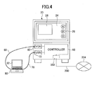
- FIG. 4 schematically illustrates a portion of an electronic information board system.
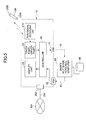
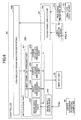
- FIG. 5 is a block diagram schematically illustrating a control system of the electronic information board. Referring to FIGs. 4 and 5 , the display unit 20 is controlled by the controller 60, and various screen operating parts 26 to be operated and an image taken from a user PC 90 are displayed in the display face 22.
- the controller 60 includes a USB socket, with which a universal serial bus (USB) cable 70 is connected, and a VGA input socket 82, with which a video graphic array (VGA) cable 80 is connected.
- USB universal serial bus
- VGA video graphic array
- the user personal computer is connected with the controller 60 through the USB socket 72 the VGA input socket 82. Further, the user PC 90 includes a storage 94 such as a magnetic disk device.
- the storage 94 stores various contents and a program such as application software for displaying contents. The operator selects a desired content among the contents stored in the storage 94 and the selected content is displayed on a monitor 92.
- the controller 60 causes the image corresponding to the image data displayed on the monitor 92 to be displayed on the user PC screen 28 of the display unit 20.
- controller 60 is connected with a communication line 200 such as an optical fiber and a network 204 such as the Internet or a local area network (LAN) through a network socket 202.
- a communication line 200 such as an optical fiber
- a network 204 such as the Internet or a local area network (LAN)
- LAN local area network
- the electronic information board system 10 includes a pen signal receiving unit 210 for receiving a detection signal transmitted from the pen-type input device 100.
- This pen signal receiving unit 210 sends the detection signal to the touch panel 24 when the pen signal receiving unit 210 receives the detection signal sent from the pen-type input device 100.
- a touch panel driver part 250 which is a control circuit of the touch panel 24, recognizes that an input operation by the pen-type input device 100 is performed upon the receipt of the detection signal transmitted from the pen-type input device 100 and outputs the detection signal to the controller 60.
- FIG. 6 is a block diagram illustrating the structure of the controller of the electronic information board.
- the controller 60 of the electronic information board system 10 includes a pen signal receiving unit 210, a controller operation system portion 220, an application part 230, an image input device part 240, and a touch panel driver part 250.
- the application part 230 includes an event signal determining part 231, an image input processing part 232, an image drawing processing part 234, a screen erasing processing part 236, and a screen operation processing part 238.
- the controller operation system portion 220 is a main control unit for managing and executing a control process performed by the controller 60.
- the application part 230 performs a control process of generating an entire image to be displayed on the display face 22 of the display unit 20, a control process of causing the image to be displayed on the user PC screen 28, and a control process of displaying transcribed graphic symbols and characters when a transcription detecting signal from the pen-type input device 100 is detected.
- the event signal determining part 231 monitors an event signal input from the controller operation system portion 220, and performs a control process corresponding to the input event signal.
- the image input processing part 232 performs a control process for displaying the image input from the user PC 90 on the user PC screen 28 on the display face 22.
- the image drawing processing part 234 generates a handwritten graphic based on the data of coordinate positions input from the touch panel 24 through the event signal determining part 231, superposes the handwritten graphic on the image already displayed, and displays the image having the superposed handwritten graphic on the display face 22.
- the image erasing processing part 236 generates a graphic of a background color of the image which is currently displayed based on the information of coordinate positions input from the touch panel 24 through the event signal determining part 231, superposes the graphic of the background color on the image already displayed, and displays the image having the superposed graphic on the display face 22. With this, the graphic of the background color is superposed on the handwritten graphic displayed on the display unit 20 to seemingly erase the handwritten graphic from the display face 22.
- the screen operation processing part 238 converts the information (a signal) of coordinate position input from the touch panel 24 to a pointing device signal such as a mouse event and perform a process by turning on or off the screen operating parts 26 displayed on the display face 22 of the display unit 20. Further, the screen operation processing part 238 transfers the information of the coordinate position, at which the pen-type input device 100 touches the display face 22 and which is detected by light emission sensor 300 and 310 provided to send light and receive the light in the touch panel 24, as a mouse down event together with the coordinate value to the controller operation system portion 220.
- the screen operation processing part 238 transfers the information of the coordinate position as a mouse up event together with the coordinate value to the controller operation system portion 220.
- the touch panel driver part 250 converts the coordinate position signal, the transcription detecting signal, and the erasure detecting signal, which are input from the pen-type input device 100 and the touch panel 24, to a predetermined event signal and transfers the converted signal to the controller operation system portion 220. Further, the touch panel driver part 250 transfers the coordinate position signal and any one of the transcription detecting signal and the erasure detecting signal to the controller operation system portion 220 when the transcription detecting signal or the erasure detecting signal is received by the pen signal receiving unit 210.
- FIG. 7 illustrates a structure of a touch panel which detects a coordinate position.
- a pair of light emission sensors 300 and 310 is arranged at upper left and upper right corners on the display face 22 of the touch panel 24, respectively.
- Reflection plates 320, 330, and 340 are arranged on the left side, the right side, and the lower side of the display face 22, respectively.
- the light emission sensor 300 arranged at the upper left corner emits infrared rays along a perpendicular plane parallel to the display face 22.
- the directions of emitting the infrared rays are entirely toward the reflection plate 330 on the right side and the reflection plate 340 on the lower side.
- the light emission sensor 310 arranged at the upper right corner emits infrared rays along the perpendicular plane parallel to the display face 22.
- the directions of emitting the infrared rays are entirely toward the reflection plate 320 on the left side and the reflection plate 340 on the lower side.
- the infrared rays emitted from the light emission sensors 300 and 310 are reflected by the reflection plates 320, 330, and 340, and the reflected light is received by the light emission sensor 300 and 310.
- the infrared rays emitted from the light emission sensors 300 and 310 are blocked at the position where the penpoint movable portion 120 or the pen tail movable portion 130 touches the display face 22.
- the light emission sensor circuit 350 detects the angle of the gradient of the position where the infrared rays are blocked relative to the horizontal direction based on detection signals from the light emission sensors 300 and 310, calculates the coordinate position using a formula for triangular surveying, and converts this coordinate position to an XY coordinate.
- a signal indicative of the coordinate position obtained by the light emission sensor circuit 350 is transferred through the controller operation system portion 220 to the image drawing processing part 234, the screen erasing processing part 236, and the screen operation processing part 238.
- FIG. 8 schematically illustrates a case where the writing unit of the pen-type input device of the embodiment of the present invention touches the display face.
- a hand H of the operator holds an outer periohery of a middle portion in the axial direction of the pen-type input device, the penpoint member 122 of the penpoint movable portion 120 in the pen-type input device 100 is caused to touch the display face 22 of the display unit 20, and the pen body 110 is pressed onto the side of the display face 22.
- the penpoint movable portion 120 slides inside the front end recess 112 of the pen body 110 in the direction X2, and the pressing portion 124b of the penpoint holding portion 124 presses the movable piece 142 of the penpoint detection switch 140 until the movable piece 142 reaches the position for switching "on".
- the penpoint detection switch 140 is switched "on", and outputs the transcription detecting signal.
- this transcription detecting signal is converted by the transmission circuit unit 180 to a wireless signal and is transmitted.
- the contact position of the penpoint movable portion 120 moves to thereby cause the handwritten characters or graphic symbols to be displayed on the display face 22.
- the front end portion 122b of the penpoint member 122 protruding on the side of the front end portion of the pen body 110 slides on the display face 22 while the front end portion 122b is deformed by receiving the contact pressure.
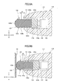
- FIGs. 9A and 9B illustrate deformation of the penpoint movable portion of the pen-type input device.
- the front end portion 112b of the penpoint member 122 which is the front end of the penpoint movable portion 120, in the pen-type input device 100 touches the display face 22, the contact pressure effects on the penpoint member 122 having elasticity. Therefore, after the penpoint member 122 repeatedly receives compressive load in the directions X1 and X2, the outer peripheral portions protruding from the penpoint holding portion 124 gradually deforms in a radius direction (the direction Y) perpendicular to the axial direction.
- FIG. 9A illustration of the deformation of the bulging portion 122c is exaggerated for easy understandings.
- the base end portion 122a of the penpoint member 122 fits into the engaging recess 124a of the penpoint holding portion 124 having a rigidity higher than the penpoint member 122 thereby restricting the deformation
- the outer peripheral side of the front end portion 122b protruding from the engaging recess 124a deforms so as to expand in radius directions (the direction Y).
- the bulging portion 122c is formed.
- the outer diameter of the bulging portion 122c gradually increases greater than the outer diameter of the wall portion 124d of the penpoint holding portion 124.
- the front end portion 122b of the penpoint member 122 touches the display face 22 thereby receiving the compressive load in the axial direction (the directions X1 and X2). Then, the penpoint movable portion 120 moves in the direction X2 to press the movable piece 142 of the penpoint detection switch 140. At this time, the bulging portion 122c expanding in the radius directions (the direction Y) is formed at the front end portion 122b of the penpoint member 122 on the side of the front end portion (the side of the direction X1) relative to the penpoint holding portion 124.
- the bulging portion 122c does not contact the front end recess 112 of the pen body 110 to thereby prevent the penpoint movable portion 120 from being inoperative. Therefore, in the pen-type input device 10, even if the bulging portion 122c is formed in the penpoint member 120, the penpoint movable portion 120 does not become inoperative, and the penpoint detection switch 140 can be switched "on” or "off". As described, the pen-type input device 10 can be continuously used and the lifetime can be prolonged.
- the pen-type input device used in the electronic information board system 10 is exemplified in the embodiment, the present invention is not limited to this and can be applied to an input device for a display apparatus having another touch panel or a terminal apparatus.
- the present invention is not limited to this structure.
- a writing unit enabled to select a plurality of colors may be provided instead of the eraser unit.
- the penpoint holding portion having the rigidity higher than that of the penpoint member fits into the outer periphery of the base end portion of the penpoint member to restrict the deformation of the outer periphery of the base end portion of the penpoint member, even if the contact pressure repeatedly effects on the penpoint member, it is possible to prevent the outer periphery of the base end portion from deforming in the radius directions, and simultaneously the feeling in causing the penpoint member to be touched with the display face is not too hard or too soft and the write feeling becomes good. Furthermore, by employing a shape of step around the outer periphery of the penpoint member, even when an impact on the penpoint member at a time of dropping the pen-type input device applied, the penpoint member is prevented from being broken.
Landscapes
- Engineering & Computer Science (AREA)
- General Engineering & Computer Science (AREA)
- Theoretical Computer Science (AREA)
- Human Computer Interaction (AREA)
- Physics & Mathematics (AREA)
- General Physics & Mathematics (AREA)
- Position Input By Displaying (AREA)
- User Interface Of Digital Computer (AREA)
Abstract
Description
- The present invention relates to a pen-type input device and electronic information board system.
- In recent years, electronic information boards such as a so-called electronic blackboard or a so-called interactive whiteboard (IWB) have been developed. For example, as disclosed in
Patent Document 1, one type of the electronic information board includes an image display device having a large screen (the diagonal dimension is, for example, 40 inches to 60 inches) using a flat panel such as a liquid crystal panel or a plasma panel, a coordinate detection device (a touch panel) which detects the coordinate of a position where a display face is touched, and a control device which causes various images (images containing a character, a number, or a figure) written on the display face of the image display device to be displayed based on coordinate data output from the coordinate detection device. - Further, it is possible to enlarge and display an image displayed by a display of a personal computer by connecting the electronic information board with a personal computer. This electronic information board can be used for presentation in a meeting.
- Further, the system of this electronic information board has a function of superposing a graphic of a handwritten character written by a pen-type input device (an object to be detected) on an image displayed on a display face by causing the pen-type input device to touch a touch panel and a function of taking a screen of a personal computer into and superposing and drawing graphics written by the pen-type input device on the screen.
- For example, Patent Document 2 discloses a pen-type input device including a writing unit which transmits a transcription detecting signal by detecting a transcribing operation when a penpoint made of, for example, an elastic member is moved while the penpoint touches a touch panel.
- In a case where the pen-type input device is used to write on an electronic information board, the pen-type input device is moved so as to go along a display surface of the electronic information board while the penpoint touches the display surface of the electronic information board, and therefore the coordinate of the position where the penpoint touches the display surface is detected by an optical sensor and characters and graphic symbols can be written like an ordinary blackboard or whiteboards. Further, the penpoint is made of a material having elasticity and the front end recess of the pen-type input device includes a detection switch for detecting a displacement caused by pressure received by the penpoint from the contacting display unit in order to improve a write feeling at a time of a contact of the penpoint with the display face of the electronic information board. Then, the electronic information board displays the characters and the graphic symbols which are written on the display face based on information of the contact position of the pen-type input device which touches the display face and a signal transmitted from the detection switch of the pen-type input device.
- Patent Document 1: Japanese Patent No.
4627781 - Patent Document 2: Japanese National Publication of International Patent Application No.
2002-509308 - At a time of the transcribing operation using the above pen-type input device, a contact pressure (a compression load) is applied onto the penpoint against the display face. Therefore, the penpoint is compressed by pressure in an axial direction so that an outer peripheral side of the penpoint expands in a radius direction. After repeated applications of the contact pressure onto the penpoint, the shape of the penpoint gradually deforms and finally the outer peripheral side of the penpoint may not return from the expanded state. After the penpoint is deformed onto the outer peripheral side as described above, the deformed part of the penpoint contacts the inner wall of the front end recess of the pen-type input device. Then, a write switch cannot be normally operated. Thus, there occurs a problem that a writing operation using the pen-type input device cannot be recognized.
- Accordingly, embodiments of the present invention provides a novel and useful pen-type input device and an electronic information board system solving one or more of the problems discussed above.
- One aspect of the embodiments of the present invention may be to provide a pen-type input device including a body shaped like a pen; a penpoint movable portion inserted into a front end recess included in the body; and a transmission part which transmits a transcription detecting signal of a contact position when the penpoint movable portion is caused to touch a display face of an electronic information board, wherein the penpoint movable portion includes a penpoint member, which is made of an elastic member and includes a front end portion caused to touch the display face, and a penpoint holding portion, which has a rigidity higher than that of the penpoint member, fits around an outer periphery of a base end portion of the penpoint member, and holds the penpoint member so as to prevent deformation of the outer periphery of the base end portion of the penpoint member.
- Additional objects and advantages of the embodiments will be set forth in part in the description which follows, and in part will be clear from the description, or may be learned by practice of the invention. Objects and advantages of the invention will be realized and attained by means of the elements and combinations particularly pointed out in the appended claims.
- It is to be understood that both the foregoing general description and the following detailed description are exemplary and explanatory only and are not restrictive of the invention as claimed.
-
-
FIG. 1 is a perspective view illustrating an electronic information board system to which a pen-type device of an embodiment of the present invention is applied. -
FIG. 2 is a longitudinal cross-sectional view of the pen-type input device of the embodiment. -
FIG. 3A is a longitudinal cross-sectional view of a penpoint structure of the pen-type input device. -
FIG. 3B is a longitudinal cross-sectional view of the penpoint structure of the pen-type input device. -
FIG. 4 schematically illustrates a control system of the electronic information board. -
FIG. 5 schematically illustrates a portion of the electronic information board system. -
FIG. 6 is a block diagram illustrating a structure of a controller of the electronic information board. -
FIG. 7 illustrates a structure of a touch panel which detects a coordinate position. -
FIG. 8 schematically illustrates a case where a writing unit of the pen-type input device of the embodiment of the present invention touches a display face. -
FIG. 9A illustrates deformation of a penpoint movable portion of the pen-type input device. -
FIG. 9B illustrates deformation of the penpoint movable portion of the pen-type input device. - A description is given below, with reference to the
FIG. 1 through FIG. 9B of embodiments of the present invention. Where the same reference symbols are attached to the same parts, repeated description of the parts is omitted. - Reference symbols typically designate as follows:
- 10: electronic information board system;
- 20: display unit;
- 22: display face;
- 24: touch panel;
- 28: user PC screen;
- 60: controller;
- 100, 400: pen-type input device;
- 100A, 400A: writing unit;
- 100B, 400B: eraser unit;
- 110: pen body;
- 111: front end;
- 112: front end recess;
- 120: penpoint movable portion;
- 122: penpoint member;
- 122a: base end portion;
- 122b: front end portion;
- 122c: bulging portion;
- 124: penpoint holding portion;
- 124a: engaging recess;
- 124b: pressing portion;
- 124c: front end side end portion;
- 124d: wall portion;
- 130: pen tail movable portion;
- 140: penpoint detection switch;
- 142, 152: movable piece;
- 150: pen tail detection switch;
- 180: transmission circuit unit;
- 182: signal input portion;
- 184: signal processing portion;
- 186: detection signal transmitting portion;
- 200: communication line;
- 202: network socket;
- 204: network;
- 210: pen signal receiving unit;
- 220: controller operation system portion;
- 230: application part;
- 231: event signal determining part;
- 232: image input processing part;
- 234: image drawing processing part;
- 236: screen erasing processing part;
- 238: screen operation processing part;
- 240: image input device part;
- 250: touch panel driver part;
- 300, 310: light emission sensor;
- 320, 330, 340: reflection plate; and
- 350: light emission sensor circuit.
-
FIG. 1 is a perspective view illustrating an electronic information board system to which a pen-type device of an embodiment of the present invention is applied. Referring toFIG. 1 , the electronicinformation board system 10 includes adisplay unit 20, astand 40, and adevice accommodating portion 50. Thedisplay unit 20 is formed by a flat panel such as a liquid crystal panel or a plasma panel. Adisplay face 22 and a touch panel (a coordinate detecting part) 24 are formed on a front surface of thedisplay unit 20. - Further, a penpoint of a pen-
type input device 100, which is dedicated for the electronicinformation board system 10, can write characters, graphic symbols, or the like onto the display face of the electronicinformation board system 10. - When the pen-
type input device 100 transmits a transcription detecting signal as a wireless signal when the penpoint at one end of the pen-type input device 100 touches thedisplay face 22. Thedisplay unit 20 displays characters, graphic symbols, or the like, which are written at a coordinate position detected by thetouch panel 24, when the transcription detecting signal transmitted from the pen-type input device 100 is received by thedisplay unit 20. - Further, when a pen tail provided at the other end of the pen-
type input device 100 touches thedisplay face 22, an erasure detecting signal is transmitted as a wireless signal. Thedisplay unit 20 erases characters, graphic symbols, or the like, which are written at a coordinate position detected by thetouch panel 24, when the erasure detecting signal transmitted from the pen-type input device 100 is received by thedisplay unit 20. When this erasure operation is performed, the same color (e.g., white) as the color of a background on the screen is given to the detected coordinate position by acontroller 60. - The
device accommodating portion 50 accommodates various devices such as a controller, a printer, or a video disk device. Further, a keyboard 30 for performing an input operation is mounted on the upper surface of thedevice accommodating portion 50. -
FIG. 2 is a longitudinal cross-sectional view of the pen-type input device of the embodiment. Referring toFIG. 2 , the pen-type input device 100 includes apen body 110 in a cylindrical shape, awriting unit 100A provided at one end of thepen body 110, and anerasure unit 100B provided at the other end of thepen body 110. In thewriting unit 100A, thepen body 110 has afront end recess 112, in which a penpointmovable portion 120 and apenpoint detection switch 140 are accommodated. Further, theerasure unit 100B includes aback end recess 114 in thepen body 110, and a pen tailmovable portion 130 and a pentail detection switch 150, which are accommodated inside theback end recess 114. - The
penpoint detection switch 140 and the pentail detection switch 150 may be a so-called push switch havingmovable pieces movable piece 142 is separated from the penpointmovable portion 120 interposing a small gap between themovable piece 142 and the penpointmovable portion 120. Themovable piece 152 is separated from the pen tailmovable portion 130 interposing a small gap between themovable piece 152 and the pen tailmovable portion 130. Therefore, themovable piece movable portion 120 and the pen tailmovable portion 130 move in the axial direction by a distance equal to or greater than a predetermined distance (equal to or greater than the small gap), respectively. When themovable piece penpoint detection switch 140 and the pentail detection switch 150 are switched from off to on to thereby output a detection signal from the pen-type input device. - One end of the
penpoint detection switch 140 is fixed to apartition wall 113 formed in a bottom of thefront end recess 112. One end of the pentail detection switch 150 is fixed to apartition wall 115 formed in a bottom of theback end recess 114. Further, a spring member pressing themovable piece 142 onto a position of switching off thepenpoint detection switch 140 is integrated in thepenpoint detection switch 140, and a spring member pressing themovable piece 152 onto a position of switching off the pentail detection switch 150 is integrated in the pentail detection switch 150. - In the pen-
type input device 100, a transmission circuit unit (a transmission part) 180 is accommodated in aninternal space 116 of thepen body 110. Thetransmission circuit unit 180 includes asignal input portion 182, asignal processing portion 184, and a detectionsignal transmitting portion 186. - Detection signals from the
penpoint detection switch 140 and the pentail detection switch 150 are input into thesignal input portion 182. Thesignal processing portion 184 converts the detection signal input through thesignal input portion 182 into a wireless signal. The detectionsignal transmitting portion 186 transmits the wireless signal (infrared rays) generated by thesignal processing portion 184. Although infrared rays are used as the wireless signal within the embodiment, the wireless signal is not limited to the infrared rays and may be a signal of electromagnetic wave, light, or sound wave. -
FIG. 3B is a longitudinal cross-sectional view of the penpoint structure of the pen-type input device. Referring toFIG. 3A , the penpointmovable portion 120 is inserted into thefront end recess 112 provided in thefront end 111 of thepen body 111 so as to be slidably moved in the axial direction (a direction of X1-X2). Further, the penpointmovable portion 120 includes apenpoint member 122 made of an elastic member and apenpoint holding portion 124 into which an outer periphery of thebase end portion 122a of the penpointmember 122 is fit. A front end portion 112b of the penpointmember 122 is shaped like a curved surface (a hemisphere face), and the outer periphery of thebase end portion 122a of the penpointmember 122 is shaped like a cylindrical column and extends in the direction of X1-X2. Said differently, thepenpoint member 122 is shaped like a rod having no step on the outer periphery of the penpointmember 122. Even if an impact is applied after dropping the pen-type input device 100, thepenpoint member 122 having improved impact resistance is not broken. It is sufficient for thepenpoint member 122 as long as no step is formed on the outer periphery, thepenpoint member 122 may be tapered to have a gradient such that an outer diameter of the penpointmember 122 on the front end side is smaller than an outer diameter of the penpointmember 122 on the side of thebase end portion 122a. In a case where the outer periphery of the penpointmember 122 is tapered, the angle of the gradient of a tapered surface relative to the axis (the central line) of the penpointmember 122 may be equal to or less than about 5 °, for example, so that thepenpoint member 122, which is fit into thepenpoint holding portion 124, can be fixed by a bond. - Further, the
penpoint holding portion 124 includes an engaging recess into which the outer periphery of thebase end portion 122a of the penpointmember 122 fits, and apressing portion 122b of the penpointmember 122 which contacts themovable piece 142 of thepenpoint detection switch 140 during the transcribing operation. Further, the engagingrecess 124a is formed inside thewall portion 124d in the cylindrical shape so as to cover the entire periphery of the base end portion of the penpointmember 122. - The elasticity modulus of the
penpoint holding portion 124 is higher than the elasticity modulus of the penpointmember 122. Therefore, when thefront end portion 122b of the penpointmember 122 contacts thedisplay face 22, thepenpoint member 122 can deform by force smaller than force enough to deform thepenpoint holding portion 124. Said differently, when the contact pressure is applied from thedisplay face 22 to thepenpoint member 122, the outer periphery of the penpointmember 122 deforms so as to outward expand earlier than thepenpoint holding portion 124. - The
penpoint detection switch 120 is switched from "off" to "on" after themovable piece 142 is pressed by thepressing portion 124b when the penpoint movable portion is pressed in the direction X2 by contact pressure generated when the penpointmovable portion 120 touches thedisplay face 22. Because afront end portion 124b of thepenpoint holding portion 124 is pushed in the direction X1 by themovable piece 142 when the penpoint detection switch is switched off, the front endside end portion 124b protrudes from thefront end recess 112 of thepen body 110 on the side of the front end in the direction X1. This protruding length S1 is, for example, S1=2 to 3 mm. - The materials of the penpoint
member 122 and thepenpoint holding portion 124 are described next. - The
penpoint member 122 is made of plastic sintered madreporite obtained by sintering rubber grains or resin grains having elasticity. For example, it is preferable to use sintered plastic that is molded as thepenpoint member 122. This sintered plastic may be obtained by sintering plastic powders such as Low Density Polyethylene (LDPE), High Density Polyethylene (HDPE), or Polypropylene (PP). - Further, the porosity of sintered plastic can be controlled by adjusting the pressing pressure, the sintering temperature, and the sintering time at a time of molding. It is possible to set the elasticity modulus and the strength to be a predetermined value by adjusting the porosity.
- Further, the
penpoint member 122 may be made of rubber such as Natural rubber (NR), Polychloroprene (CR), Nitrile rubber (NBR), Ethylene Propylene Rubber (EPDM), Butyl rubber (IIR), polyurethane (U), fluoro rubber (FKM), Silicone rubber (VMQ). - As described, the
penpoint member 122 is preferably made of a material (e.g., the above rubber, resin, plastic sintered madreporite, or foamed plastic) simultaneously having appropriate hardness and appropriate softness in order to optimize feeling in causing thefront end portion 122b to touch thedisplay face 22 and write feeling. - The
penpoint holding portion 124 is made of a resin or a metal having a rigidity higher than that of the penpointmember 122. The material of thepenpoint holding portion 124 is preferably ABS resin, PC resin, or a metal such as alloy of ABS/PC, iron, stainless. - Referring to
FIG. 3B , when thefront end portion 122b of the penpointmember 122 touches thedisplay face 22, thepenpoint member 122 is pressed in the direction of X2 due to the contact pressure. Therefore, thepenpoint member 122 moves in the direction of X2 together with thepenpoint holding portion 124. At this time, the moving distance of the penpointmember 122 and thepenpoint holding portion 124 is the same as the movable range where themovable piece 142 of thepenpoint detection switch 140 is switched from "off" to "on". The movable range where themovable piece 142 of thepenpoint detection switch 140 is switched from "off" to "on" is less than protruding length S1. - Therefore, if the
penpoint member 122 is pressed in the direction X2 by the contact pressure to switch themovable piece 142 of thepenpoint detection switch 140 from "off" to "on", thefront end portion 124c of thepenpoint holding portion 124 is protruded on the side of thefront end portion 122b relative to thefront end recess 112 of thepen body 110. At this time, the protruding length S2 is, for example, about 0.05 mm to 2 mm, preferably about 0.1 mm to 1 mm. As described, in a case where the compressive load acts on thepenpoint member 122 by the contact pressure, thewall portion 124d outside the engagingrecess 124a of thepenpoint holding portion 124 protrudes from thefront end recess 112 of the pen body on the side of the front end portion. - Next, the protruding length S2 is described. For example, when the protruding length S2 is long, the protruding length of the penpoint of the penpoint
member 122, which is a length of a portion of the penpointmember 122 protruding from thefront end recess 112 of thepen body 110, becomes long. When the protruding length of the penpoint is long, a distance between a position where an operator holds thepen body 110 and a position where thepenpoint member 122 touches thedisplay face 22 becomes long. In this case, a variation of a writing position during writing becomes too great to cause uncomfortable feeling in writing. Therefore, it is necessary to shorten the length of the penpointmember 122 in order to increase the protruding length S2 of thepenpoint holding portion 124 and decrease the length of the penpoint. In this case of shortening thepenpoint member 122, flexibility of the penpointmember 122 like a cushion is low. Therefore, there occurs a problem that write feeling becomes hard such that a back action at the time when thepenpoint member 122 touches the display face reaches a hand of an operator. - Then, if a material having a low elasticity modulus is used for the
penpoint member 122, a portion of the penpointmember 122 protruding from thefront end portion 124c of thepenpoint holding portion 124 on the side of thefront end portion 122b (in the direction X1) expands in a radius direction when thepenpoint member 122 receives the contact pressure by being pressed against thedisplay face 22. However, a portion of the penpointmember 122 on a side of the base end (in the direction X2) relative to thefront end portion 124c of thepenpoint holding portion 124 is held by thepenpoint holding portion 124 having the rigidity higher than that of the penpointmember 122 so as not to expand in the radius direction. Said differently, because the write feeling is softened in the penpointmovable portion 120, if the portion of the penpointmember 122, which protrudes on the side of thefront end portion 122b from thepenpoint holding portion 124, expands on the side of the outer periphery, the pen-type input device 100 is structured so that the deformed (expanded) part does not interfere with thefront end recess 114 of thepen body 110. - The above described materials for the
penpoint member 122 and thepenpoint holding portion 124 were tested in order to compare the deformation of the penpoints and the write feeling during transcription. Here, the elasticity modulus of a sintered plastic as the material of thepenpoint members 122 is set to be 100 MPa to 300 MPa, where write feeling is assumed to be good, by adjusting the porosity. This test includes an
- As a result of the evaluation in the above test, it was known that when the elasticity modulus of the penpoint
member 122 is low (for example, about 50 MPa), thepenpoint holding portion 124 did not deform but thepenpoint member 122 did extremely deform to show a high degree of deformation. Further, under a high load, the penpoint member was broken. - On the other hand, when the elasticity modulus of the penpoint
member 122 is high (for example, about 250 MPa to 300 MPa), obtained were many evaluations that a back action caused when the penpoint member touched thedisplay face 22 was directly transferred to the hand of the operator and therefore the write feeling is hard. - It was known from these results illustrated in Table 1 that the material of the
penpoint holding portion 124 had no problem if the elasticity modulus of the material is about 2.1 GPa or if a material having a higher elasticity modulus than 2.1 GPa was used. - Further, the elasticity modulus of the material of the penpoint
member 122 was preferably in a range of 50 MPa to 300 MPa, more preferably in a range of 100 MPa to 200 MPa. -
FIG. 4 schematically illustrates a portion of an electronic information board system.FIG. 5 is a block diagram schematically illustrating a control system of the electronic information board. Referring toFIGs. 4 and5 , thedisplay unit 20 is controlled by thecontroller 60, and variousscreen operating parts 26 to be operated and an image taken from auser PC 90 are displayed in thedisplay face 22. - Further, the
controller 60 includes a USB socket, with which a universal serial bus (USB)cable 70 is connected, and aVGA input socket 82, with which a video graphic array (VGA)cable 80 is connected. - The user personal computer (PC) is connected with the
controller 60 through theUSB socket 72 theVGA input socket 82. Further, theuser PC 90 includes astorage 94 such as a magnetic disk device. Thestorage 94 stores various contents and a program such as application software for displaying contents. The operator selects a desired content among the contents stored in thestorage 94 and the selected content is displayed on amonitor 92. - Therefore, when image data displayed on the
monitor 92 of theuser PC 90 is transferred from theuser PC 90 through theUSB cable 70 and theVGA cable 80 to thecontroller 60, thecontroller 60 causes the image corresponding to the image data displayed on themonitor 92 to be displayed on theuser PC screen 28 of thedisplay unit 20. - Further, the
controller 60 is connected with acommunication line 200 such as an optical fiber and anetwork 204 such as the Internet or a local area network (LAN) through anetwork socket 202. - Further, as illustrated in
FIG. 5 , the electronicinformation board system 10 includes a pensignal receiving unit 210 for receiving a detection signal transmitted from the pen-type input device 100. This pensignal receiving unit 210 sends the detection signal to thetouch panel 24 when the pensignal receiving unit 210 receives the detection signal sent from the pen-type input device 100. With this, a touchpanel driver part 250, which is a control circuit of thetouch panel 24, recognizes that an input operation by the pen-type input device 100 is performed upon the receipt of the detection signal transmitted from the pen-type input device 100 and outputs the detection signal to thecontroller 60. -
FIG. 6 is a block diagram illustrating the structure of the controller of the electronic information board. Referring toFIG. 6 , thecontroller 60 of the electronicinformation board system 10 includes a pensignal receiving unit 210, a controlleroperation system portion 220, anapplication part 230, an imageinput device part 240, and a touchpanel driver part 250. Further, theapplication part 230 includes an eventsignal determining part 231, an imageinput processing part 232, an imagedrawing processing part 234, a screen erasingprocessing part 236, and a screenoperation processing part 238. - The controller
operation system portion 220 is a main control unit for managing and executing a control process performed by thecontroller 60. - The
application part 230 performs a control process of generating an entire image to be displayed on thedisplay face 22 of thedisplay unit 20, a control process of causing the image to be displayed on theuser PC screen 28, and a control process of displaying transcribed graphic symbols and characters when a transcription detecting signal from the pen-type input device 100 is detected. - The event
signal determining part 231 monitors an event signal input from the controlleroperation system portion 220, and performs a control process corresponding to the input event signal. - The image
input processing part 232 performs a control process for displaying the image input from theuser PC 90 on theuser PC screen 28 on thedisplay face 22. - The image
drawing processing part 234 generates a handwritten graphic based on the data of coordinate positions input from thetouch panel 24 through the eventsignal determining part 231, superposes the handwritten graphic on the image already displayed, and displays the image having the superposed handwritten graphic on thedisplay face 22. - The image erasing
processing part 236 generates a graphic of a background color of the image which is currently displayed based on the information of coordinate positions input from thetouch panel 24 through the eventsignal determining part 231, superposes the graphic of the background color on the image already displayed, and displays the image having the superposed graphic on thedisplay face 22. With this, the graphic of the background color is superposed on the handwritten graphic displayed on thedisplay unit 20 to seemingly erase the handwritten graphic from thedisplay face 22. - The screen
operation processing part 238 converts the information (a signal) of coordinate position input from thetouch panel 24 to a pointing device signal such as a mouse event and perform a process by turning on or off thescreen operating parts 26 displayed on thedisplay face 22 of thedisplay unit 20. Further, the screenoperation processing part 238 transfers the information of the coordinate position, at which the pen-type input device 100 touches thedisplay face 22 and which is detected bylight emission sensor touch panel 24, as a mouse down event together with the coordinate value to the controlleroperation system portion 220. Further, in a case where the pen-type input device 100 is moved while the pen-type input device 100 touches thedisplay face 22 of thetouch panel 24, the screenoperation processing part 238 transfers the information of the coordinate position as a mouse up event together with the coordinate value to the controlleroperation system portion 220. - The touch
panel driver part 250 converts the coordinate position signal, the transcription detecting signal, and the erasure detecting signal, which are input from the pen-type input device 100 and thetouch panel 24, to a predetermined event signal and transfers the converted signal to the controlleroperation system portion 220. Further, the touchpanel driver part 250 transfers the coordinate position signal and any one of the transcription detecting signal and the erasure detecting signal to the controlleroperation system portion 220 when the transcription detecting signal or the erasure detecting signal is received by the pensignal receiving unit 210. -
FIG. 7 illustrates a structure of a touch panel which detects a coordinate position. Referring toFIG. 7 , a pair oflight emission sensors display face 22 of thetouch panel 24, respectively.Reflection plates display face 22, respectively. - The
light emission sensor 300 arranged at the upper left corner emits infrared rays along a perpendicular plane parallel to thedisplay face 22. The directions of emitting the infrared rays are entirely toward thereflection plate 330 on the right side and thereflection plate 340 on the lower side. Thelight emission sensor 310 arranged at the upper right corner emits infrared rays along the perpendicular plane parallel to thedisplay face 22. The directions of emitting the infrared rays are entirely toward thereflection plate 320 on the left side and thereflection plate 340 on the lower side. - In a case where nothing touches the
display face 22, the infrared rays emitted from thelight emission sensors reflection plates light emission sensor - Here, in a case where the penpoint
movable portion 120 or the pen tailmovable portion 130 touches thedisplay face 22, the infrared rays emitted from thelight emission sensors movable portion 120 or the pen tailmovable portion 130 touches thedisplay face 22. Then, the lightemission sensor circuit 350 detects the angle of the gradient of the position where the infrared rays are blocked relative to the horizontal direction based on detection signals from thelight emission sensors emission sensor circuit 350 is transferred through the controlleroperation system portion 220 to the imagedrawing processing part 234, the screen erasingprocessing part 236, and the screenoperation processing part 238. -
FIG. 8 schematically illustrates a case where the writing unit of the pen-type input device of the embodiment of the present invention touches the display face. Referring toFIG. 8 , a hand H of the operator holds an outer periohery of a middle portion in the axial direction of the pen-type input device, thepenpoint member 122 of the penpointmovable portion 120 in the pen-type input device 100 is caused to touch thedisplay face 22 of thedisplay unit 20, and thepen body 110 is pressed onto the side of thedisplay face 22. Then, the penpointmovable portion 120 slides inside thefront end recess 112 of thepen body 110 in the direction X2, and thepressing portion 124b of thepenpoint holding portion 124 presses themovable piece 142 of thepenpoint detection switch 140 until themovable piece 142 reaches the position for switching "on". Thus, thepenpoint detection switch 140 is switched "on", and outputs the transcription detecting signal. Then, this transcription detecting signal is converted by thetransmission circuit unit 180 to a wireless signal and is transmitted. - As described above, when the pen-
type input device 100 is moved while thepenpoint detection switch 140 is switched on, the contact position of the penpointmovable portion 120 moves to thereby cause the handwritten characters or graphic symbols to be displayed on thedisplay face 22. At this time, thefront end portion 122b of the penpointmember 122 protruding on the side of the front end portion of thepen body 110 slides on thedisplay face 22 while thefront end portion 122b is deformed by receiving the contact pressure. - Here, the state of deformation of the penpoint
member 122 is described. -
FIGs. 9A and 9B illustrate deformation of the penpoint movable portion of the pen-type input device. Referring toFIGs. 9A and 9B , when the front end portion 112b of the penpointmember 122, which is the front end of the penpointmovable portion 120, in the pen-type input device 100 touches thedisplay face 22, the contact pressure effects on thepenpoint member 122 having elasticity. Therefore, after thepenpoint member 122 repeatedly receives compressive load in the directions X1 and X2, the outer peripheral portions protruding from thepenpoint holding portion 124 gradually deforms in a radius direction (the direction Y) perpendicular to the axial direction. Referring toFIG. 9A , illustration of the deformation of the bulgingportion 122c is exaggerated for easy understandings. - Because the
base end portion 122a of the penpointmember 122 fits into the engagingrecess 124a of thepenpoint holding portion 124 having a rigidity higher than thepenpoint member 122 thereby restricting the deformation, the outer peripheral side of thefront end portion 122b protruding from the engagingrecess 124a deforms so as to expand in radius directions (the direction Y). Thus, the bulgingportion 122c is formed. As described, when the outer peripheral side of thefront end portion 122b of the penpointmember 122 deforms in the radius directions by the contact pressure against thedisplay face 22, the outer diameter of the bulgingportion 122c gradually increases greater than the outer diameter of thewall portion 124d of thepenpoint holding portion 124. - Referring to
FIG. 9B , in a case where a transcribing operation is performed using thepenpoint member 122, which is deformed, thefront end portion 122b of the penpointmember 122 touches thedisplay face 22 thereby receiving the compressive load in the axial direction (the directions X1 and X2). Then, the penpointmovable portion 120 moves in the direction X2 to press themovable piece 142 of thepenpoint detection switch 140. At this time, the bulgingportion 122c expanding in the radius directions (the direction Y) is formed at thefront end portion 122b of the penpointmember 122 on the side of the front end portion (the side of the direction X1) relative to thepenpoint holding portion 124. - Therefore, the bulging
portion 122c does not contact thefront end recess 112 of thepen body 110 to thereby prevent the penpointmovable portion 120 from being inoperative. Therefore, in the pen-type input device 10, even if the bulgingportion 122c is formed in thepenpoint member 120, the penpointmovable portion 120 does not become inoperative, and thepenpoint detection switch 140 can be switched "on" or "off". As described, the pen-type input device 10 can be continuously used and the lifetime can be prolonged. - Although the pen-type input device used in the electronic
information board system 10 is exemplified in the embodiment, the present invention is not limited to this and can be applied to an input device for a display apparatus having another touch panel or a terminal apparatus. - Further, although the structure that the writing unit is provided at one end of the pen-type input device and the eraser unit is provided at the other end is exemplified in the embodiment, the present invention is not limited to this structure. For example, a writing unit enabled to select a plurality of colors may be provided instead of the eraser unit.
- Within the embodiment, because the penpoint holding portion having the rigidity higher than that of the penpoint member fits into the outer periphery of the base end portion of the penpoint member to restrict the deformation of the outer periphery of the base end portion of the penpoint member, even if the contact pressure repeatedly effects on the penpoint member, it is possible to prevent the outer periphery of the base end portion from deforming in the radius directions, and simultaneously the feeling in causing the penpoint member to be touched with the display face is not too hard or too soft and the write feeling becomes good. Furthermore, by employing a shape of step around the outer periphery of the penpoint member, even when an impact on the penpoint member at a time of dropping the pen-type input device applied, the penpoint member is prevented from being broken.
- All examples and conditional language recited herein are intended for pedagogical purposes to aid the reader in understanding the principles of the invention and the concepts contributed by the inventor to furthering the art, and are to be construed as being without limitation to such specifically recited examples and conditions, nor does the organization of such examples in the specification relate to a showing of the superiority or inferiority of the invention. Although the pen-type input device has been described in detail, it should be understood that various changes, substitutions, and alterations could be made thereto without departing from the spirit and scope of the invention.
Claims (7)
- A pen-type input device comprising:a body shaped like a pen;a penpoint movable portion inserted into a front end recess included in the body; anda transmission part which transmits a transcription detecting signal of a contact position when the penpoint movable portion is caused to touch a display face of an electronic information board,wherein the penpoint movable portion includes
a penpoint member, which is made of an elastic member and includes a front end portion caused to touch the display face, and
a penpoint holding portion, which has a rigidity higher than that of the penpoint member, fits around an outer periphery of a base end portion of the penpoint member, and holds the penpoint member so as to prevent deformation of the outer periphery of the base end portion of the penpoint member. - The pen-type input device according to claim 1,
wherein the penpoint holding portion protrudes from a front end of the body while the penpoint member does not touch the display face. - The pen-type input device according to claim 1 or 2,
wherein, in the penpoint holding portion, the front end portion of the penpoint member touches the display face, and
when a transcription detecting signal is transmitted from the transmission part, a front end portion of the penpoint holding portion is positioned on a side of the front end portion of the penpoint member. - The pen-type input device according to any one of claims 1 to 3,
wherein the front end portion of the penpoint member to touch the display face includes a curved surface, and
a part of the front end portion between the front end portion and the base end portion has a shape of a cylindrical column or a tapered shape. - The pen-type input device according to any one of claims 1 to 4,
wherein an elasticity modulus of the penpoint holding portion is higher than an elasticity modulus of the penpoint member. - The pen-type input device according to any one of claims 1 to 5,
wherein the penpoint member is made of a plastic sintered madreporite formed by sintering rubber grains or resin grains, and
the penpoint holding portion is made of a resin material or a metal having a rigidity higher than that of the plastic sintered madreporite. - An electronic information board system comprising:the pen-type input device according to claim 1;a display unit including the display face which the pen-type input device is caused to touch;a coordinate detecting part which detects a coordinate where the pen-type input device touches the display face; anda controller which causes to display a graphic corresponding to the touch of the pen-type input device at the coordinate position detected by the coordinate detecting part.
Applications Claiming Priority (1)
| Application Number | Priority Date | Filing Date | Title |
|---|---|---|---|
| JP2013019209A JP6127548B2 (en) | 2013-02-04 | 2013-02-04 | Pen-type input device and electronic information board system |
Publications (2)
| Publication Number | Publication Date |
|---|---|
| EP2763002A2 true EP2763002A2 (en) | 2014-08-06 |
| EP2763002A3 EP2763002A3 (en) | 2014-12-31 |
Family
ID=50064454
Family Applications (1)
| Application Number | Title | Priority Date | Filing Date |
|---|---|---|---|
| EP14153795.1A Withdrawn EP2763002A3 (en) | 2013-02-04 | 2014-02-04 | Pen-type input device and electronic information board system |
Country Status (4)
| Country | Link |
|---|---|
| US (1) | US9563288B2 (en) |
| EP (1) | EP2763002A3 (en) |
| JP (1) | JP6127548B2 (en) |
| CN (1) | CN103970305B (en) |
Cited By (2)
| Publication number | Priority date | Publication date | Assignee | Title |
|---|---|---|---|---|
| GB2534032A (en) * | 2015-01-07 | 2016-07-13 | Promethean Ltd | User interaction device |
| CN109872574A (en) * | 2019-02-28 | 2019-06-11 | 安徽信息工程学院 | An intelligent blackboard structure |
Families Citing this family (14)
| Publication number | Priority date | Publication date | Assignee | Title |
|---|---|---|---|---|
| JP6524639B2 (en) | 2014-10-24 | 2019-06-05 | 株式会社リコー | Input device and electronic information board system |
| JP2016085662A (en) | 2014-10-28 | 2016-05-19 | 株式会社リコー | Input device and electronic information board system |
| JP6550725B2 (en) * | 2014-11-07 | 2019-07-31 | セイコーエプソン株式会社 | Electronic pen |
| TWI564773B (en) * | 2015-08-05 | 2017-01-01 | 緯創資通股份有限公司 | Optical touch system and optical touch apparatus thereof |
| CN108700962B (en) * | 2016-03-08 | 2021-07-13 | 株式会社和冠 | Board for pen input device and method for producing the board for pen input device |
| CN205692135U (en) * | 2016-05-25 | 2016-11-16 | 广州视睿电子科技有限公司 | Reinforced pen point and pressure pen |
| WO2019117191A1 (en) * | 2017-12-15 | 2019-06-20 | 三菱鉛筆株式会社 | Touch pen |
| JP7325951B2 (en) * | 2017-12-15 | 2023-08-15 | 三菱鉛筆株式会社 | touch pen |
| CN109880221B (en) * | 2019-03-28 | 2021-08-27 | 广州视源电子科技股份有限公司 | Composite material for touch control pen point, pen point and preparation method |
| CN109957165B (en) * | 2019-03-28 | 2021-12-10 | 广州视焓科技有限公司 | Touch pen point composite material, touch pen and pen point forming method thereof |
| CN112346582B (en) * | 2019-08-08 | 2022-07-22 | 华为技术有限公司 | Touch control pen and electronic equipment |
| EP3822746A1 (en) | 2019-11-15 | 2021-05-19 | Microsoft Technology Licensing, LLC | Mouse input function for pen-shaped writing, reading or pointing devices |
| CN111831139B (en) * | 2020-07-09 | 2024-01-23 | 京东方科技集团股份有限公司 | Smart pen with force-measuring tip and interaction method thereof |
| CN113296619B (en) * | 2021-05-13 | 2022-12-20 | Oppo广东移动通信有限公司 | Pen type input device and pen point device thereof |
Citations (6)
| Publication number | Priority date | Publication date | Assignee | Title |
|---|---|---|---|---|
| JP2002509308A (en) | 1997-12-16 | 2002-03-26 | シャピラ、ラン | Electronic pen |
| US20080257613A1 (en) * | 2007-04-19 | 2008-10-23 | Yuji Katsurahira | Position indicator and coordinate input device |
| JP4627781B2 (en) | 1998-05-11 | 2011-02-09 | 株式会社リコー | Coordinate input / detection device and electronic blackboard system |
| US20110298709A1 (en) * | 2010-06-01 | 2011-12-08 | Vladimir Vaganov | System and method for digital recording of handpainted, handdrawn and handwritten information |
| US20120086674A1 (en) * | 2010-10-12 | 2012-04-12 | Kim Keyng Hun | Touch screen operating pen |
| US20120146958A1 (en) * | 2010-12-14 | 2012-06-14 | Wacom Co., Ltd. | Position indicator |
Family Cites Families (15)
| Publication number | Priority date | Publication date | Assignee | Title |
|---|---|---|---|---|
| JPH0337058Y2 (en) | 1985-08-08 | 1991-08-06 | ||
| JPH1027059A (en) | 1996-07-12 | 1998-01-27 | Hitachi Seiko Ltd | Coordinate indicator for coordinate input device |
| JPH10161795A (en) * | 1996-12-03 | 1998-06-19 | Mitsubishi Pencil Co Ltd | Input pen for capacitive coordinate input pad |
| JPH11259227A (en) | 1998-03-12 | 1999-09-24 | Ricoh Co Ltd | Pen type input device |
| JP2000105671A (en) | 1998-05-11 | 2000-04-11 | Ricoh Co Ltd | Coordinate input / detection device and electronic blackboard system |
| JP3420078B2 (en) * | 1998-09-02 | 2003-06-23 | タチカワ株式会社 | Writing implement |
| JP4315423B2 (en) * | 2003-07-23 | 2009-08-19 | キヤノン株式会社 | Input pen |
| JP2005131943A (en) * | 2003-10-30 | 2005-05-26 | Pilot Ink Co Ltd | Nib for pigment ink and writing instrument |
| JP4522442B2 (en) * | 2007-08-20 | 2010-08-11 | 三菱鉛筆株式会社 | Knock-type writing instrument with shock absorber |
| US20090277697A1 (en) * | 2008-05-09 | 2009-11-12 | Smart Technologies Ulc | Interactive Input System And Pen Tool Therefor |
| US8753813B2 (en) * | 2009-12-07 | 2014-06-17 | Northwestern University | Generation of combinatorial patterns by deliberate tilting of a polymer-pen array |
| US20120146957A1 (en) * | 2010-12-09 | 2012-06-14 | Kelly Allan Dunagan | Stylus tip device for touch screen |
| JP5575630B2 (en) * | 2010-12-14 | 2014-08-20 | 株式会社サクラクレパス | Pen for writing instruments |
| JP2012126096A (en) * | 2010-12-17 | 2012-07-05 | Sakura Color Products Corp | Application tool and chip for application tool |
| JP4840891B1 (en) | 2011-04-19 | 2011-12-21 | 株式会社ワコム | Cordless type position indicator |
-
2013
- 2013-02-04 JP JP2013019209A patent/JP6127548B2/en active Active
-
2014
- 2014-02-03 US US14/170,767 patent/US9563288B2/en not_active Expired - Fee Related
- 2014-02-04 EP EP14153795.1A patent/EP2763002A3/en not_active Withdrawn
- 2014-02-07 CN CN201410151175.2A patent/CN103970305B/en not_active Expired - Fee Related
Patent Citations (6)
| Publication number | Priority date | Publication date | Assignee | Title |
|---|---|---|---|---|
| JP2002509308A (en) | 1997-12-16 | 2002-03-26 | シャピラ、ラン | Electronic pen |
| JP4627781B2 (en) | 1998-05-11 | 2011-02-09 | 株式会社リコー | Coordinate input / detection device and electronic blackboard system |
| US20080257613A1 (en) * | 2007-04-19 | 2008-10-23 | Yuji Katsurahira | Position indicator and coordinate input device |
| US20110298709A1 (en) * | 2010-06-01 | 2011-12-08 | Vladimir Vaganov | System and method for digital recording of handpainted, handdrawn and handwritten information |
| US20120086674A1 (en) * | 2010-10-12 | 2012-04-12 | Kim Keyng Hun | Touch screen operating pen |
| US20120146958A1 (en) * | 2010-12-14 | 2012-06-14 | Wacom Co., Ltd. | Position indicator |
Cited By (3)
| Publication number | Priority date | Publication date | Assignee | Title |
|---|---|---|---|---|
| GB2534032A (en) * | 2015-01-07 | 2016-07-13 | Promethean Ltd | User interaction device |
| EP3043241A1 (en) * | 2015-01-07 | 2016-07-13 | Promethean Ltd | User interaction device |
| CN109872574A (en) * | 2019-02-28 | 2019-06-11 | 安徽信息工程学院 | An intelligent blackboard structure |
Also Published As
| Publication number | Publication date |
|---|---|
| JP2014149760A (en) | 2014-08-21 |
| CN103970305B (en) | 2017-04-12 |
| JP6127548B2 (en) | 2017-05-17 |
| CN103970305A (en) | 2014-08-06 |
| EP2763002A3 (en) | 2014-12-31 |
| US20140218344A1 (en) | 2014-08-07 |
| US9563288B2 (en) | 2017-02-07 |
Similar Documents
| Publication | Publication Date | Title |
|---|---|---|
| US9563288B2 (en) | Pen-type input device and electronic information board system | |
| JP5451599B2 (en) | Multimodal smart pen computing system | |
| US8922530B2 (en) | Communicating stylus | |
| US10359865B2 (en) | Stylus, stylus signal processing method, and stylus signal processing device | |
| JP6106983B2 (en) | Image display device, image display system, method and program | |
| US20030080946A1 (en) | Portable computer and related method for preventing input interruption by write-tracking an input region | |
| JP2006500680A (en) | Method and system for 3D handwriting recognition | |
| KR102120772B1 (en) | Image erasing device for electronic chalkboard system and control method thereof, display apparatus and control method thereof, and electronic chalkboard system | |
| JP7449236B2 (en) | Electronic eraser and writing information processing system | |
| KR101176104B1 (en) | Interactive electric board system and management method using optical sensing pen | |
| CN103543851A (en) | Input method and electronic device using pen input device | |
| US20080062138A1 (en) | Computer system and control method therefor | |
| US20130321351A1 (en) | Graphical display with optical pen input | |
| WO2007088430A1 (en) | System, device, method and computer program product for using a mobile camera for controlling a computer | |
| JP6079185B2 (en) | Pen-type input device and electronic information board system | |
| KR102758797B1 (en) | Touch pen Used on Interactive Whiteboard | |
| JP2018041430A (en) | Handwriting input device | |
| US9898101B2 (en) | Input device and electronic information board system with a movable object movable in a slant direction | |
| US20140354600A1 (en) | Input device and electronic information board system | |
| US8913008B2 (en) | Image data generation using a handheld electronic device | |
| KR20140069460A (en) | Frindle related communication terminal | |
| CA2817318C (en) | Graphical display with optical pen input | |
| CN114253406B (en) | Touch pen structure and trigger module | |
| JP2012208576A (en) | Drawing apparatus | |
| CN117631850A (en) | Touch panel device |
Legal Events
| Date | Code | Title | Description |
|---|---|---|---|
| PUAI | Public reference made under article 153(3) epc to a published international application that has entered the european phase |
Free format text: ORIGINAL CODE: 0009012 |
|
| 17P | Request for examination filed |
Effective date: 20140204 |
|
| AK | Designated contracting states |
Kind code of ref document: A2 Designated state(s): AL AT BE BG CH CY CZ DE DK EE ES FI FR GB GR HR HU IE IS IT LI LT LU LV MC MK MT NL NO PL PT RO RS SE SI SK SM TR |
|
| AX | Request for extension of the european patent |
Extension state: BA ME |
|
| PUAL | Search report despatched |
Free format text: ORIGINAL CODE: 0009013 |
|
| AK | Designated contracting states |
Kind code of ref document: A3 Designated state(s): AL AT BE BG CH CY CZ DE DK EE ES FI FR GB GR HR HU IE IS IT LI LT LU LV MC MK MT NL NO PL PT RO RS SE SI SK SM TR |
|
| AX | Request for extension of the european patent |
Extension state: BA ME |
|
| RIC1 | Information provided on ipc code assigned before grant |
Ipc: G06F 3/0354 20130101AFI20141124BHEP |
|
| STAA | Information on the status of an ep patent application or granted ep patent |
Free format text: STATUS: EXAMINATION IS IN PROGRESS |
|
| 17Q | First examination report despatched |
Effective date: 20180503 |
|
| STAA | Information on the status of an ep patent application or granted ep patent |
Free format text: STATUS: THE APPLICATION IS DEEMED TO BE WITHDRAWN |
|
| 18D | Application deemed to be withdrawn |
Effective date: 20210121 |