EP2762844B1 - Sichtfensteranordnung für einseitige Installation und Verfahren für dessen Installation - Google Patents
Sichtfensteranordnung für einseitige Installation und Verfahren für dessen Installation Download PDFInfo
- Publication number
- EP2762844B1 EP2762844B1 EP14154005.4A EP14154005A EP2762844B1 EP 2762844 B1 EP2762844 B1 EP 2762844B1 EP 14154005 A EP14154005 A EP 14154005A EP 2762844 B1 EP2762844 B1 EP 2762844B1
- Authority
- EP
- European Patent Office
- Prior art keywords
- viewing window
- window assembly
- panel
- enclosure
- attachment members
- Prior art date
- Legal status (The legal status is an assumption and is not a legal conclusion. Google has not performed a legal analysis and makes no representation as to the accuracy of the status listed.)
- Active
Links
Images




Classifications
-
- G—PHYSICS
- G02—OPTICS
- G02B—OPTICAL ELEMENTS, SYSTEMS OR APPARATUS
- G02B27/00—Optical systems or apparatus not provided for by any of the groups G02B1/00 - G02B26/00, G02B30/00
- G02B27/02—Viewing or reading apparatus
- G02B27/022—Viewing apparatus
-
- E—FIXED CONSTRUCTIONS
- E06—DOORS, WINDOWS, SHUTTERS, OR ROLLER BLINDS IN GENERAL; LADDERS
- E06B—FIXED OR MOVABLE CLOSURES FOR OPENINGS IN BUILDINGS, VEHICLES, FENCES OR LIKE ENCLOSURES IN GENERAL, e.g. DOORS, WINDOWS, BLINDS, GATES
- E06B7/00—Special arrangements or measures in connection with doors or windows
- E06B7/28—Other arrangements on doors or windows, e.g. door-plates, windows adapted to carry plants, hooks for window cleaners
- E06B7/30—Peep-holes; Devices for speaking through; Doors having windows
-
- G—PHYSICS
- G02—OPTICS
- G02B—OPTICAL ELEMENTS, SYSTEMS OR APPARATUS
- G02B13/00—Optical objectives specially designed for the purposes specified below
- G02B13/14—Optical objectives specially designed for the purposes specified below for use with infrared or ultraviolet radiation
-
- G—PHYSICS
- G02—OPTICS
- G02B—OPTICAL ELEMENTS, SYSTEMS OR APPARATUS
- G02B7/00—Mountings, adjusting means, or light-tight connections, for optical elements
-
- H—ELECTRICITY
- H05—ELECTRIC TECHNIQUES NOT OTHERWISE PROVIDED FOR
- H05K—PRINTED CIRCUITS; CASINGS OR CONSTRUCTIONAL DETAILS OF ELECTRIC APPARATUS; MANUFACTURE OF ASSEMBLAGES OF ELECTRICAL COMPONENTS
- H05K5/00—Casings, cabinets or drawers for electric apparatus
- H05K5/02—Details
-
- E—FIXED CONSTRUCTIONS
- E06—DOORS, WINDOWS, SHUTTERS, OR ROLLER BLINDS IN GENERAL; LADDERS
- E06B—FIXED OR MOVABLE CLOSURES FOR OPENINGS IN BUILDINGS, VEHICLES, FENCES OR LIKE ENCLOSURES IN GENERAL, e.g. DOORS, WINDOWS, BLINDS, GATES
- E06B1/00—Border constructions of openings in walls, floors, or ceilings; Frames to be rigidly mounted in such openings
- E06B1/56—Fastening frames to the border of openings or to similar contiguous frames
- E06B1/60—Fastening frames to the border of openings or to similar contiguous frames by mechanical means, e.g. anchoring means
- E06B1/6046—Clamping means acting perpendicular to the wall opening; Fastening frames by tightening or drawing them against a surface parallel to the opening
- E06B1/6061—Clamping means acting perpendicular to the wall opening; Fastening frames by tightening or drawing them against a surface parallel to the opening with separate clamping means acting on opposite wall or associated surfaces
-
- E—FIXED CONSTRUCTIONS
- E06—DOORS, WINDOWS, SHUTTERS, OR ROLLER BLINDS IN GENERAL; LADDERS
- E06B—FIXED OR MOVABLE CLOSURES FOR OPENINGS IN BUILDINGS, VEHICLES, FENCES OR LIKE ENCLOSURES IN GENERAL, e.g. DOORS, WINDOWS, BLINDS, GATES
- E06B3/00—Window sashes, door leaves, or like elements for closing wall or like openings; Layout of fixed or moving closures, e.g. windows in wall or like openings; Features of rigidly-mounted outer frames relating to the mounting of wing frames
- E06B3/54—Fixing of glass panes or like plates
- E06B3/58—Fixing of glass panes or like plates by means of borders, cleats, or the like
- E06B3/5892—Fixing of window panes in openings in door leaves
-
- Y—GENERAL TAGGING OF NEW TECHNOLOGICAL DEVELOPMENTS; GENERAL TAGGING OF CROSS-SECTIONAL TECHNOLOGIES SPANNING OVER SEVERAL SECTIONS OF THE IPC; TECHNICAL SUBJECTS COVERED BY FORMER USPC CROSS-REFERENCE ART COLLECTIONS [XRACs] AND DIGESTS
- Y10—TECHNICAL SUBJECTS COVERED BY FORMER USPC
- Y10T—TECHNICAL SUBJECTS COVERED BY FORMER US CLASSIFICATION
- Y10T29/00—Metal working
- Y10T29/49—Method of mechanical manufacture
- Y10T29/49826—Assembling or joining
Definitions
- Visual inspection is a common technique for analyzing equipment and systems for both maintenance and troubleshooting. Often times, the components to be inspected are housed within an enclosure for safety, operability, or other reasons. In such an instance, it may be preferable to enable visual inspection of such components while the enclosure is closed. In many cases, visual inspection cannot be performed through a solid enclosure, so in order to perform the inspection, a viewing window assembly may be installed into the enclosure.
- a viewing window assembly may be installed into the enclosure.
- One illustrative example is infrared imaging of high voltage electrical equipment within an electrical cabinet. Although, imaging of high voltage electrical equipment within an electrical cabinet may be in many different wavelengths, including visible light wavelengths.
- Infrared (IR) imaging has increasingly been used in the preventative maintenance of high voltage electrical circuits and components.
- An IR image of the components can often reveal hot spots which may indicate malfunctioning, improperly connected, or overloaded components. Timely identification of problem components can save on system downtime and expenses associated with replacing blown or destroyed components.
- a thermographer should view the components with an IR camera while the components are operating or energized.
- this can be difficult because electrical components are often kept in high voltage electrical cabinets.
- an IR camera requires a line of sight to deliver a suitably accurate thermal image, components within a cabinet cannot be imaged adequately without either opening the cabinet or providing some other view into the cabinet.
- thermography industry As an alternative to imaging cool components by opening the cabinet door, the thermography industry has placed fixed IR transmitting windows in a panel or door of high voltage electrical cabinets. These windows can provide a line of sight within the cabinet so that it may be inspected without being opened while the components within are energized.
- Previous IR windows aimed toward this purpose have required access to both sides of a panel that makes up a portion of the cabinet for installation. As such, the cabinet must at least be opened, if not disassembled, to permit such two-sided access to the desired panel in a way that permits the requisite amount of maneuverability for installation. Additionally, repair or replacement of such a window may require further opening and/or disassembly of the cabinet to allow the appropriate access. Furthermore, many previous windows have required multiple holes in the panel of the cabinet for installation - a first hole for holding the main, viewing portion of the window, and auxiliary holes for securing the window or window assembly to the cabinet.
- Publication WO 2012/037575 A1 discloses a viewing window assembly and method for installing such a window with all the features of the preambles of claims 1 and 7.
- Embodiments of the present invention relate to a viewing window assembly for installation into a single hole from a single side of a panel of an enclosure, and a method of installing the same.
- Various embodiments and methods fall within the scope of the invention as defined by the appended claims.
- a method for installing a viewing window assembly into a panel of an enclosure comprising all the features of independent claim 1.
- the viewing window assembly may comprise a plurality of bolts, each having an associated nut, wherein actuating components of the viewing window assembly comprises rotating said bolts.
- the nuts may comprise at least one tooth such that actuating components of the viewing window assembly results in the at least one tooth penetrating a surface coating of the enclosure.
- the at least one tooth may penetrate a surface coating of the panel and creates an electrically conductive connection between the viewing window assembly and the enclosure.
- the nuts may engage the inner-rim of the created hole.
- the rotation of the nuts about the longitudinal axes of the associated bolts may be limited.
- the actuating components of the viewing window assembly may compress a gasket, thereby creating a seal between the interior and exterior of the enclosure.
- the enclosure may be an electrical cabinet.
- the viewing window assembly may be electrically grounded to the panel.
- the viewing window assembly may be an infrared viewing window assembly.
- the single hole in the panel may be created with a punch-tool, or may be a hole in the panel that already exists.
- a viewing window assembly designed for mounting in a single hole of a panel of an enclosure is provided, the viewing window assembly comprising all the features of independent claim 7.
- the viewing window assembly may comprise a gasket between the frame and the enclosure when the window is secured to the enclosure.
- the viewing window assembly may comprising a cover for covering at least a portion of the optic, and a gasket between the frame and the cover when the cover is in the closed position.
- the cover may be attached to the frame by a hinge.
- Each of the respective attachment members may comprise at least one tooth for engaging the enclosure.
- the direction of movement of each of the respective attachment members need not perpendicular to the plane of the window.
- the direction of movement of each of the respective attachment members may form an angle between 30 and 60 degrees with the plane of the window.
- the one or more actuators may be bolts, and the one or more associated attachment members may be nuts, in which case actuating the actuators may comprise rotating the bolts.
- the enclosure may comprise an electrical cabinet.
- the optic may comprises an infrared-transmissive material.
- the viewing window assembly may further comprise a retaining ring for removably securing the optic in the frame, the retaining ring and optic being removable via the front side of the viewing window assembly.
- Each of the respective attachment members may be partially rotatable and may comprise a threaded portion and a wing portion, and configured such that when an actuator is actuated, the wing portion may rotate outward, away from the central axis and additionally may engage an inner surface of the panel.
- the wing portion of each of the respective attachment members may comprise at least one tooth on the surface that engages the panel.
- Each of the respective attachment members may comprise a wedge portion for engaging the inner edge of the hole.
- a viewing window assembly designed for mounting in a single hole, the viewing window assembly comprising:
- the viewing window assembly may further comprise a stop configured to at least partially limit the rotation of the nut.
- the at least one nut may further comprise a plurality of teeth.
- the longitudinal axis of the bolts may form a non-90 degree angle with the plane of the optic.
- the bolts may form between a 30 and 60 degree angle with the plane of the optic.
- At least one of the at least two nuts may comprise a wing nut having a threaded portion and a wing portion, and be configured such that when a bolt is rotated, the wing portion may rotate outward, away from the central axis, and additionally translate toward the frame.
- the wing portion of the at least one nut further comprises at least one tooth.
- the optic may comprise an infrared transmissive material.
- the viewing window assembly may further comprise a cover for at least partially covering the optic.
- the viewing window assembly comprise a front side, a back side, a frame, and an optic defining a central axis.
- One or more actuators are actuatable from the front side of the assembly, and are each coupled to an attachment member on the back side of the assembly, which faces the interior of an enclosure through a hole in a panel when mounted therein.
- an actuator may cause its respective attachment member to move in a direction away from the central axis and towards the panel of the enclosure.
- the attachment member may engage an inner surface of the panel of the enclosure and secure the viewing window assembly thereto utilizing a single hole and accessing it from a single side.
- Actuators may comprise bolts passing through the frame at an angle in order to move attachment members such as nuts both towards the panel and away from the central axis.
- Embodiments of the invention further relate to a method for installing a viewing window assembly into a panel of an enclosure.
- a method for installing a viewing window assembly into a panel of an enclosure may comprise providing a hole in the panel and the viewing window assembly including a frame and an optic.
- the method may further comprise inserting the viewing window assembly through the hole from outside of the enclosure and actuating components of the viewing window assembly from outside of the enclosure. Actuating the components may secure the viewing window assembly to the panel while only penetrating said panel through a single hole.
- Additional aspects of the invention may comprise a gasket to create a seal surrounding the hole to discourage the flow of particulates such as dust into the enclosure from the exterior, or a cover for selectively covering the optic.
- the viewing window assembly may also be electrically grounded to the enclosure by engaging a conducting surface and/or by penetrating an insulating surface of the panel with a conducting element such as a plurality of teeth.
- Visual inspection is a technique with many applications.
- it is advantageous to be able to observe a scene of an object or objects inside of an enclosure.
- optically transmitting windows have been installed in panels of enclosures in order to allow appropriate imagers to observe the desired electromagnetic signals coming from within the enclosure.
- many previous such windows and window assemblies have been inconvenient to install. Often, installation requires access to both sides of a panel of the enclosure in order to install the window therein. Additionally, multiple holes in the panel are often necessary in order to secure the panel to the enclosure and/or electrically ground the window to the panel.
- Embodiments of the present invention involve a viewing window assembly not requiring access to both sides of a panel for installation or repair. Viewing, herein, is taken to mean observing at least a portion of an electromagnetic spectrum, and may be done with the eye, a camera, or any other optical sensing element.
- the assembly described herein may comprise infrared window assemblies, wherein the window is designed to transmit at least, or alternatively, at most, infrared radiation. Additional embodiments of the invention may be designed to transmit additional or alternative portions of the spectrum, such as visible and/or ultraviolet wavelengths.
- the window assembly of the present invention require only a single hole for installation and securement of the window assembly to an enclosure such as an electrical cabinet.
- the window may be transmissive to various portions of the electromagnetic spectrum, including visible, infrared, and ultraviolet radiation.
- like reference numbers will be used for like components.
- like components may appear distinct among differing embodiments of the invention while remaining functionally similar. In such a case, like reference numerals may be used to describe functionally similar components.
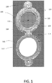
- FIG. 1 illustrates one embodiment of the present invention.
- FIG. 1 shows a front side of a viewing window assembly 100, facing away from and mounted into a single hole in a panel 150 of an enclosure, created by a standard Greenlee® punch or other known hole creating methods, for example. While the window assembly is installed through the hole from a single side, it is noted that it may be necessary to access both sides of the panel in order to appropriately create the single hole in the panel. If the hole already exists, certain embodiments of the invention provide the ability to install the window assembly while accessing only the front side of the panel. Among some embodiments, the hole may range in size between two and five inches in diameter, and further may be a standard punch size.
- the viewing window assembly 100 comprises a frame 102 and an optic 106, which may be selectively transmissive to certain portions of the spectrum.
- the illustrated embodiment further comprises actuators 104 for securing the viewing window assembly 100 to the panel 150, and, in some embodiments, compressing a gasket between the frame 102 and the panel 150 to create a seal between the interior and exterior of the enclosure. This may prevent the release of potentially harmful substances from the enclosure into the surrounding environment external thereto, or the undesired entry ofparticulates such as dust into the enclosure.
- the seal created is airtight, however it need not be.
- the viewing window assembly 100 may additionally comprise a retaining ring 108 for securing the optic 106 to the frame.
- the retaining ring 108 may be removed from the front side in order to remove the optic 106 from outside of the enclosure, for example from the front of the enclosure.
- the optic may be removed from the viewing window assembly and/or replaced by another optic without interior access to the enclosure or removing the assembly therefrom.
- the optic may define a central axis of the assembly, which travels through the center of the optic in a direction normal thereto.
- the optic may be a circle, as shown in FIG. 1 , but may be formed in other shapes as well, with the central axis being definable through a point within the boundary of the shape.
- the optic 106 may comprise a material that permits the transmission of radiation at desired wavelengths.
- the optic may comprise a crystal glass material for allowing the transmittance of IR energy, such as calcium fluoride, barium fluoride, or any other IR-transmissive optic material. If the window is meant for transmitting visible or ultraviolet light, additional materials may be used.
- the viewing window assembly 100 may further comprise a cover 110, as shown in FIG. 1 .
- the cover is intended to cover the front side of the optic 106 from the environment external to the enclosure to prevent, for example, damage to the optic from outside of the enclosure or the release of anything from inside the enclosure to the external environment should the optic break.
- the window assembly further comprises a cover gasket 112 seated between the cover 110 and the frame 102 when the cover 110 is in the closed position. This cover gasket 112 may create a seal between the interior and exterior of the enclosure if the optic should break or fail in some other way.
- FIG. 1 shows the cover gasket 112 secured to the cover 110 while it is in the open position.
- the cover 110 is removable from the optic, and may be completely removable from the viewing window assembly 100.
- the cover 110 may be attached to the viewing window assembly 100, via a hinge 114, for example.
- FIG. 2 shows a frame of an embodiment of a viewing window assembly for installing into a single hole in and from a single side of an enclosure.
- Frame 102 comprises two sides, a front side with a first diameter 220, and a back side with a second diameter 222, the second diameter 222 smaller than the first 220.
- the diameter of the smaller, back side is smaller than but comparable to the size of the hole in a panel so that the portion of the frame of this diameter may be placed in or through the hole in the panel.
- the diameter of the front side is larger than that of the hole, creating something of a shoulder 218, not allowing the entire frame 102 to pass through the hole.
- FIG. 5a shows a back view of an embodiment of the invention, shown as installed into a hole in a panel and looking at it from the inside of the enclosure.
- this figure shows the rear view of FIG. 1 , with attachment members 328 engaging the panel 150 from inside of the enclosure.
- FIGS. 3a-3c show a cross-sectional view of the installation of an embodiment of the invention into a single hole from a single side of a panel of an enclosure, taken, for example, at 3-3 in FIG. 5a .
- FIG. 3a shows a cross-sectional view of the assembly 100 prior to installation into the hole 332 in the panel 150.
- the assembly has a front side 224 facing away from the enclosure 334 and a back side 226, opposite the front and facing toward the enclosure. This designation of the front side referring to the side facing externally from an enclosure and back side referring to the side facing internally to the enclosure will be used throughout the disclosure unless otherwise noted.
- the assembly further comprises actuators 104, extending longitudinally through a frame 102 and coupled to attachment members 328.
- the attachment members may be freely rotatable, rotatably fixed, or rotatable only through a limited extent, and are translatable by actuating the actuators, while the actuators may be actuatable from the front side of the assembly.
- the translation of attachment members may be limited to a certain distance.
- attachment members 328 reside in channels 330 formed in the back side of the frame 102. These channels may be configured relative to the attachment members 328 so as to disallow rotation of thereof. Since the attachment members 328 are translatable, in some embodiments of the invention, the channel 330 in the frame 102 may prevent rotation of the attachment member 328 in any translated position.
- actuators 104 may comprise bolts and attachment members may comprise nuts, wherein actuating the bolts comprises turning said bolts, resulting in translation of the nuts. It will be appreciated that in a typical nut-bolt configuration, if the nut is free to rotate it may be difficult to achieve translation of the nut along the bolt, as the two may spin in unison.
- nut herein, refers to any member threaded to engage a bolt or other threaded member.
- the actuators extend through the frame at a non-90 degree angle, wherein the end of the actuators on the front side 224 of the assembly 100 are located radially inward from the end of the actuators on the back side 226 of the assembly, nearer the central axis.
- the actuators may cause the attachment members to translate in a direction with a component that is either radially inward or radially outward relative to the central axis.
- this angle may range between 30 and 60 degrees.
- the viewing window assembly 100 is shown as being located completely externally to and in front of the enclosure 334, with the attachment members 328 located such that they are within the area defined by the hole 332 in the panel 150 and are located some distance away from the frame 102 in the direction of the actuators 104.
- FIG. 3b shows the viewing window assembly of FIG. 3a as it is being inserted into the hole 332 in the panel 150 from the front side of the panel. Attachment members 328 are positioned such that they may move through the hole 332 towards the inside of the enclosure 334.
- FIG. 3c shows the viewing window assembly inserted further into the hole 332 in the panel 150.
- the shoulder of the frame 102 of the assembly 100 abuts the panel 150 in a way such that the assembly 100 cannot travel further into the enclosure 334.
- the embodiment shown in FIGS. 3a-3c comprises a gasket positioned between the frame 102 and the panel 150, creating a seal therebetween if compressed.
- the actuators 104 may be actuated such that the attachment members 328 are drawn both radially outward, away from the central axis, and towards the panel 150. Attachment members eventually contact a part of the panel 150, compressing the gasket and securing the viewing window assembly to the enclosure 334.
- FIG. 4a shows a magnified view of a portion of an embodiment of the invention similar to that of FIGS. 3a-3c , zoomed in around one of the attachment members and actuators and with portions of the assembly 100 inserted into a hole 332 in a panel 150 of an enclosure 334.
- the radial extent of attachment member 328 does not extend outward beyond the edge of the hole 332 in the panel 150, as shown by location lines 438. This allows for the attachment member 328 to be inserted into the hole 332 of the panel 150.
- the frame 102 of the assembly 100 may be pressed to the front side of the panel 150 outside of the hole 332.
- gasket 336 is present to create a seal between the interior and exterior of the enclosure 334 that circumvents the hole 332.
- the actuator 104 shown is positioned at a non-90 degree angle relative to the plane of the panel 150, allowing for the coupled attachment member 328 to translate not only towards or away from the panel 150 but also laterally (radially) relative to the hole 332. Among various embodiments, this angle may range from 30 to 60 degrees. Note that in the configuration shown in FIG. 4a , since the attachment member 328 is located in a position along the actuator 104 so that it may pass through the hole 332 in the panel 150. Thus, the attachment member 328 need not translate further radially inward for installation or attachment purposes.
- radially inward translation inward may be limited to or near such a position to prevent the attachment member 328 from becoming decoupled from the actuator 104. Additionally, note that, although the attachment member 328 of the embodiment in FIG. 4a extends such a distance along the actuator, it still lies in the channel 330 of the frame 102 which may prevent rotation of the attachment member 328.
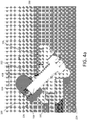
- FIG. 4b shows a magnified view of the embodiment of FIG. 4a with the attachment member 328 translated by way of actuating the actuator 104.
- the attachment member 328 has translated within the channel 330 and in the longitudinal direction along the axis of the actuator 104, contacting an inside surface of the panel 150.
- the inside surface of the panel 150 may comprise any part of the panel that is not exposed to the enclosure's external surroundings, including the inner edge 444 of the hole 332 in the panel 150.
- the attachment member 328 contacts the inner edge 444 of the hole 332 in the panel 150.
- the attachment member 328 may comprise at least one tooth on the surface that contacts the panel 150, and in some embodiments may comprise a plurality of teeth.
- teeth may comprise any pointed element, and may at least partially penetrate the panel 150 or a coating thereon to facilitate a secure connection and/or to provide electrical conductivity between the viewing window assembly and the enclosure. This electrical conductivity may be advantageous if the enclosure is an electrical cabinet, as the window assembly may build up a charge if not grounded to the enclosure.
- FIG. 5a shows an embodiment of a viewing window assembly installed into a panel of an enclosure such as an electrical cabinet, viewed from inside of the enclosure.
- FIG. 5a shows the back side of the viewing window assembly 100 as it is facing the interior of the enclosure.
- the viewing window assembly 100 comprises an optic 106 defining a central axis, a frame, and attachment members 328.
- attachment members are coupled to actuators 104 which, when actuated from the front side of the assembly outside the enclosure, translate the attachment members 328 in a direction with a component towards or away from the central axis.
- FIG. 5a shows the attachment members abutting the panel 150 of the enclosure, securing the viewing window assembly 100 in place.
- the attachment members 328 are able to engage the interior of the panel 150, on the inside surface of or near the hole 332 in the panel 150.
- the pressure applied from the attachment members 328 onto the panel 150 squeezes the panel and the frame 102 together, securing the frame, and thus the assembly 100 to the panel 150.
- the squeezing together of the panel and frame may further compress a gasket, creating a seal between the interior and exterior of the panel.
- the seal may be an airtight seal.
- FIG. 5b shows a perspective view of an attachment member of FIG. 5a , zoomed in on the back side of the viewing window assembly, viewed from inside of the enclosure.
- the attachment member 328 of FIG. 5b further comprises teeth 540, which engage an inside surface of the panel 150 near the hole 332.
- the teeth may engage the planar inside surface of the panel 150 or the inner edge of the hole in the panel 150.
- the teeth 540 act to penetrate the surface of the panel 150 in order to securely attach the assembly 100 to the panel 150 and also to facilitate an electrical connection therebetween. In doing so, the viewing window assembly 100 becomes grounded to the panel 150, reducing the possibility of a build-up of electric charge on the assembly.
- any embodiment described herein that engages a panel may comprise at least one tooth for such purposes. While the exemplary embodiments illustrated thus far comprise similarly shaped attachment members, other embodiments of the invention may comprise entirely different attachment members.
- FIG. 6a and Bb show another embodiment of the invention.
- the embodiment in FIGS. 6a and 6b is very similar to that shown in previous embodiments, such that only the main differences between the embodiments are indicated.
- FIG. 6a shows the back side of a viewing window assembly from inside of an enclosure, configured to allow installation and removal of the viewing window assembly to and from a hole in a panel of the enclosure.
- the viewing window assembly 100 is shown inserted into but not secured to a panel 150, further comprising a frame 102, an optic 106, attachment members 628, and an actuator 104 associated with each attachment member 628.
- FIG. 1 shows the back side of a viewing window assembly from inside of an enclosure, configured to allow installation and removal of the viewing window assembly to and from a hole in a panel of the enclosure.
- the viewing window assembly 100 is shown inserted into but not secured to a panel 150, further comprising a frame 102, an optic 106, attachment members 628, and an actuator 104 associated with each attachment member 628.
- attachment members 628 are positioned substantially within the boundary of the portion of the frame 102 inserted into the hole 332 in the panel 150 such that at least portions of the attachment members 628 also pass through the hole 332.
- portions of the frame 102 pass through the hole 332, other portions may act as a stop from preventing the entire frame 102 from passing through the hole 332, as described above with regard to FIG. 2 .
- This stopping portion contacts the panel outside the enclosure as the frame 102 is being inserted, preventing it from traveling through the hole beyond a certain distance.
- the viewing window assembly may further comprise a gasket positioned between the stopping portion and the panel so that, when compressed, the gasket may create a seal around the hole 332 between the interior and exterior of the enclosure.
- this seal may be airtight to prevent the inward or outward flow of air between the enclosure and surrounding environment.
- the seal me be such that it is substantially dustproof, which is to say it inhibits the flow of dust into the enclosure through the hole in which the viewing window assembly resides.
- the attachment members are rotatable only through a certain range of angular positions due to the shape of the attachment members and to portions of the frame that prevent the attachment members from rotating freely.
- the attachment members rotate between a position that extends beyond the extent of the panel hole and a position that retracts the attachment members within the extent of the panel hole.
- the attachment members are coupled to the actuators such that, if able, an attachment member will rotate upon actuation of the associated actuator. However, if the attachment member is unable to rotate, it will translate in a direction along the longitudinal central axis of the associated actuator.
- the viewing window assembly may be installed into or removed from outside of a single hole in a panel of an enclosure.
- the actuator is positioned assymetrically on the attachment member 628, such that the attachment member 628 includes a wing portion 642 that rotates inward ( FIG 6a ) to a retracted position and rotates outward ( FIG. 6b ) to an extended position.
- the attachment member 628 rotates asymmetrically about the actuator 104, and is also translatable, parts of the wing portion may generally move in a direction radially outwards or inwards and also towards or away from the panel 150.
- FIG. 6b shows the back side of a viewing window assembly from inside the enclosure, configured to secure the viewing window assembly to the enclosure.
- the attachment members 628 of FIG. 6a have rotated partially outward, such that the wing portion now overlaps a portion of the panel 150.
- attachment members 628 may have translated axially along the actuator to engage the inside surface of the panel 150.
- actuators 104 may comprise bolts and attachment members 628 may comprise nuts, for example wing nuts, and in which the nuts are allowed to partially rotate.
- the associated nuts may rotate as well, however only through a certain range, in this case the point where the distal end of the nut (the wing) overhangs the panel.
- the bolt begins to rotate within the nut, causing the nut to translate along the longitudinal direction of the bolt.
- the nut may translate such that it engages the panel, wherein subsequent rotation of the bolt presses the window assembly and the panel together, potentially compressing a gasket located therebetween to create a seal.
- the nut may further comprise at least one tooth for engaging the panel and puncturing a surface coating that may be applied thereon.
- the viewing window assembly may be removed from the hole in the panel enclosure.
- the bolts may be rotated from the front side (not shown) of the viewing window assembly, implying that the assembly may be installed into a single hole in a panel of an enclosure entirely from the outside of the enclosure.
- the viewing window assembly of FIGS. 6a and 6b may comprise an infrared window assembly, wherein the optic comprises an infrared transmissive material.
- FIGS. 7a-7c Yet another embodiment of the invention is shown in FIGS. 7a-7c .
- FIG. 7a shows a perspective view of the back side of a viewing window assembly, such as an infrared window assembly, in a panel of an enclosure, configured to allow installation and removal of the viewing window assembly to and from a hole in the panel.
- This embodiment functions similarly to that of FIG. 4a and 4b , and like components will be represented by like numerals.
- the embodiment shown comprises a frame 102, attachment members 728 residing in channels 330 to limit rotation, and an actuator 104 associated with each of the attachment members.
- FIG 7a shows a similar configuration as FIG.
- attachment members 728 fit and extend through the hole and are coupled to actuators 104 accessible from the front side of the window assembly 100. Actuating the actuators 104 causes the attachment members 728 to translate in a direction with a component at least radially outward, away from the central axis 116, and towards the panel 150, eventually resulting in the attachment members 728 engaging the panel 150 as shown in FIG. 7b .
- FIG. 7b shows a similar configuration as does FIG. 4b , wherein the attachment members 728 have been moved such that they now engage an inside surface of the panel 150.
- actuators 104 may be actuated from the front side of the assembly 100 in order to retract the attachment members 728 away from the central axis 116 and back toward the panel 150 until they are engaged therewith.
- attachment members 728 may comprise elongated nuts, each with a wedge portion and including a threaded hole therethrough as shown in FIG. 7b
- actuators 104 may comprise bolts, threadably engaged with elongated wedges via the hole therethrough.
- the nuts may be arranged in such a way that they are prevented from rotating freely by portions of the window frame 102, such as the channels described above relative to FIGS. 3a and 4a ). Thus, as the bolts are rotated from the front of the window assembly 100, the nuts may retract towards the panel 150 until they are engaged therewith.
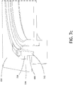
- FIG. 7c shows a portion of a cross section of the embodiment shown in FIG. 7b , taken at line 7-7.
- FIG. 7c illustrates a possible configuration of the engagement of an attachment member with the panel.
- the attachment member comprises a wedge portion 742 such that, as the attachment member translates toward the panel, the wedge portion 742 engages the inner edge 444 of the hole.
- the wedge portion 742 may allow for an electrical connection between the window assembly 100 and the panel 150 via the uncoated inner edge 444 of the hole.
- an additional portion of the attachment member may engage the back side 226 of the panel as well, as shown in the figure.
Landscapes
- Physics & Mathematics (AREA)
- General Physics & Mathematics (AREA)
- Optics & Photonics (AREA)
- Engineering & Computer Science (AREA)
- Civil Engineering (AREA)
- Structural Engineering (AREA)
- Health & Medical Sciences (AREA)
- Toxicology (AREA)
- Microelectronics & Electronic Packaging (AREA)
- Casings For Electric Apparatus (AREA)
- Securing Of Glass Panes Or The Like (AREA)
Claims (15)
- Verfahren zum Installieren einer Sichtfensteranordnung (100) in einem Wandteil (150) eines Gehäuses mit einer Innenseite und einer Außenseite, wobei das Verfahren aufweist:Bereitstellen eines einzelnen Lochs (332) in dem Wandteil (150);Bereitstellen der Sichtfensteranordnung einschließlich eines Rahmens (102), einer Optik (106) und betätigbarer Komponenten (104/328),
gekennzeichnet durchEinsetzen der Sichtfensteranordnung (100) in das einzelne Loch von der Außenseite des Gehäuses aus; undBetätigen der betätigbaren Komponenten (104/328) der Sichtfensteranordnung (100) von der Außenseite des Gehäuses aus, um die Sichtfensteranordnung an dem Wandteil zu befestigen, wobei die Sichtfensteranordnung durch den Wandteil nur durch das einzelne Loch durchtritt. - Verfahren nach Anspruch 1, wobei die Sichtfensteranordnung ferner eine Mehrzahl von Schrauben (104) aufweist, die jeweils eine zugehörige Mutter (328) haben, und wobei ein Betätigen der betätigbaren Komponenten (104/328) der Sichtfensteranordnung ein Drehen der Schrauben aufweist.
- Verfahren nach Anspruch 2, wobei die Muttern (328) mindestens eine Zacke (540) aufweisen, derart, dass ein Betätigen der betätigbaren Komponenten (104/328) der Sichtfensteranordnung dazu führt, dass die mindestens eine Zacke (540) eine Oberflächenbeschichtung des Gehäuses durchdringt, wodurch optional eine elektrisch leitende Verbindung zwischen der Sichtfensteranordnung (100) und dem Gehäuse hergestellt wird.
- Verfahren nach Anspruch 2 oder 3, wobei die Muttern (328) in den Innenkranz des einzelnen Lochs (332) eingreifen.
- Verfahren nach Anspruch 2, 3 oder 4, wobei eine Drehung der Muttern (328) um die Längsachsen der zugehörigen Schrauben (104) begrenzt ist.
- Verfahren nach einem der vorhergehenden Ansprüche, wobei die betätigbaren Komponenten der Sichtfensteranordnung einen Dichtring (336) zusammenpressen, wobei das Betätigen der betätigbaren Komponenten eine Abdichtung zwischen dem Inneren und Äußeren des Gehäuses herstellt.
- Sichtfensteranordnung (100), ausgelegt für den Einbau in ein einzelnes Loch (332) eines Wandteils (150) eines Gehäuses, wobei der Wandteil eine Außenseite und eine Innenseite hat, wobei die Sichtfensteranordnung (100) aufweist:einen Rahmen (102);eine Optik (106), die eine Mittelachse (116) definiert;eine Vorderseite (224), wobei die Vorderseite von dem Gehäuse abgewandt ist, wenn die Sichtfensteranordnung darin eingebaut wird;eine Rückseite (226), wobei die Rückseite der Innenseite des Gehäuses zugewandt ist, wenn die Sichtfensteranordnung darin eingebaut wird; undbetätigbare Komponenten (104/328), die aufweisen:ein oder mehrere Betätigungselemente (104), die jeweils mit einem Befestigungselement (328) verbunden sind, das an der Rückseite (226) der Sichtfensteranordnung positioniert ist, wobei das eine oder die mehreren Betätigungselemente (104) von der Vorderseite der Sichtfensteranordnung aus betätigbar sind,
dadurch gekennzeichnet, dassdie jeweiligen Befestigungselemente (328) konfigurierbar sind, um zu gestatten, dass jedes durch das einzelne Loch (332) des Wandteils hindurchtritt, wenn die Sichtfensteranordnung durch dieses eingesetzt wird, unddie jeweiligen Befestigungselemente (328) so angeordnet sind, dass beim Betätigen, wenn die Sichtfensteranordnung durch das einzelne Loch (332) eingesetzt wird, das eine oder die mehreren Betätigungselemente (104) mindestens einen Abschnitt der einen oder der mehreren jeweiligen Befestigungselemente (328) mindestens in eine von der Mittelachse (116) der Sichtfensteranordnung (100) abgewandte Richtung bewegen, derart, dass der mindestens eine Abschnitt des einen oder der mehreren jeweiligen Befestigungselemente (328) in eine Innenfläche (444) des Wandteils des Gehäuses auf einem Umfang des einzelnen Lochs (332) eingreifen, um die Sichtfensteranordnung an dem Wandteil des Gehäuses nur von einer Seite der Platte aus und über das einzelne Loch zu installieren und zu befestigen. - Sichtfensteranordnung nach Anspruch 7, ferner aufweisend einen Dichtring (336) zwischen dem Rahmen (102) und dem Gehäuse, wenn das Fenster an dem Gehäuse befestigt wird.
- Sichtfensteranordnung nach Anspruch 7 oder 8, ferner aufweisend eine Abdeckung (110) zum Abdecken mindestens eines Abschnitts der Optik (106) und einen Dichtring (112) zwischen dem Rahmen (102) und der Abdeckung (110), wenn sich die Abdeckung in einer geschlossenen Position befindet.
- Sichtfensteranordnung nach einem der Ansprüche 7 bis 9, wobei jedes der jeweiligen Befestigungselemente (328) mindestens eine Zacke (540) zum Eingreifen in das Gehäuse aufweist.
- Sichtfensteranordnung nach einem der Ansprüche 7 bis 10, wobei die Bewegungsrichtung von jedem der jeweiligen Befestigungselemente (328) nicht senkrecht zu einer Ebene der Optik (106) erfolgt, beispielsweise wobei die Bewegungsrichtung von jedem der jeweiligen Befestigungselemente (328) einen Winkel zwischen 30 und 60 Grad mit der Ebene der Optik (106) bildet.
- Sichtfensteranordnung nach einem der Ansprüche 7 bis 11, wobei das eine oder die mehreren Betätigungselemente (104) Schrauben sind, das eine oder die mehreren zugehörigen Befestigungselemente (328) Muttern sind, und wobei ein Betätigen der Betätigungselemente ein Drehen der Schrauben aufweist.
- Sichtfensteranordnung nach einem der Ansprüche 7 bis 12, wobei das Gehäuse einen Schaltschrank aufweist.
- Sichtfensteranordnung nach einem der Ansprüche 7 bis 13, ferner aufweisend einen Haltering (108) zum entfernbaren Befestigen der Optik (106) in dem Rahmen (102), wobei der Haltering und die Optik über die Vorderseite der Sichtfensteranordnung entfernbar sind.
- Verfahren zum Installieren der Sichtfensteranordnung nach einem der Ansprüche 7 bis 14 in einem einzelnen Loch (332) in einem Wandteil (150), aufweisend:Einsetzen der Rückseite (226) der Sichtfensteranordnung (100) in das einzelne Loch (332), derart, dass das eine oder die mehreren Befestigungselemente (328), die jeweils mit einem des einen oder der mehreren Betätigungselemente (104) verbunden sind, durch das einzelne Loch des Wandteils hindurchtreten; undvon der Vorderseite des Wandteils aus Betätigen des einen oder der mehreren Betätigungselemente (104), um das eine oder die mehreren Befestigungselemente (328) zu veranlassen, sich mindestens in eine von der Mittelachse (116) der Sichtfensteranordnung abgewandte Richtung zu bewegen.
Applications Claiming Priority (1)
| Application Number | Priority Date | Filing Date | Title |
|---|---|---|---|
| US13/759,742 US9217869B2 (en) | 2013-02-05 | 2013-02-05 | Viewing window assembly for single-sided installation |
Publications (2)
| Publication Number | Publication Date |
|---|---|
| EP2762844A1 EP2762844A1 (de) | 2014-08-06 |
| EP2762844B1 true EP2762844B1 (de) | 2016-12-21 |
Family
ID=50071439
Family Applications (1)
| Application Number | Title | Priority Date | Filing Date |
|---|---|---|---|
| EP14154005.4A Active EP2762844B1 (de) | 2013-02-05 | 2014-02-05 | Sichtfensteranordnung für einseitige Installation und Verfahren für dessen Installation |
Country Status (3)
| Country | Link |
|---|---|
| US (2) | US9217869B2 (de) |
| EP (1) | EP2762844B1 (de) |
| CN (1) | CN103974574B (de) |
Families Citing this family (9)
| Publication number | Priority date | Publication date | Assignee | Title |
|---|---|---|---|---|
| US11394180B2 (en) | 2016-01-08 | 2022-07-19 | IRISS Holdings, Inc. | Replacement panels for electrical distribution cabinets for the monitoring of targeted components and connections |
| EP3615952B1 (de) | 2017-04-25 | 2024-11-27 | Iriss Holdings, Inc. | Paneel zur hörbaren überwachung elektrischer bauteile und zur erfassung elektrischer fehler |
| CN107069457A (zh) * | 2017-04-27 | 2017-08-18 | 淮阴工学院 | 高压电柜免开门式外部紧固红外窗口及其安装方法 |
| US11670490B2 (en) * | 2017-09-29 | 2023-06-06 | Taiwan Semiconductor Manufacturing Co., Ltd. | Integrated circuit fabrication system with adjustable gas injector |
| CN110350416A (zh) * | 2018-04-04 | 2019-10-18 | 厦门华电开关有限公司 | 气密性观察窗模块、观察窗及其应用 |
| DE102018125499A1 (de) * | 2018-10-15 | 2020-04-16 | Emka Beschlagteile Gmbh & Co. Kg | Sichtfenster für RLT-Anlagen und Klimakammern |
| US12292334B2 (en) * | 2018-11-14 | 2025-05-06 | Alpinco Bv | Thermal infrared sensor that can be fixed onto infrared windows |
| CN111323131A (zh) * | 2018-12-13 | 2020-06-23 | 河北泰中岩电气设备科技有限公司 | 一种嵌入式内安装抗燃弧短弧防爆型红外测温视窗 |
| CN110344738A (zh) * | 2019-06-24 | 2019-10-18 | 六安堰山自动化设备销售有限公司 | 一种用于智能家居系统的防盗门 |
Family Cites Families (8)
| Publication number | Priority date | Publication date | Assignee | Title |
|---|---|---|---|---|
| US3896463A (en) * | 1974-01-02 | 1975-07-22 | Donald M Laskey | Accessory mounting apparatus for camera |
| US7079334B2 (en) * | 2003-02-04 | 2006-07-18 | Holliday Graham R | Infrared sight glass for aftermarket fitment |
| US7286309B2 (en) | 2004-01-28 | 2007-10-23 | Holliday Graham R | Infrared sight glass for aftermarket fitment |
| US7391566B2 (en) * | 2006-05-02 | 2008-06-24 | Leica Microsystems Cms Gmbh | Microscope having eyepiece reticle slider |
| US8023818B2 (en) | 2008-07-24 | 2011-09-20 | Fluke Corporation | Articulating infrared window |
| US8407938B2 (en) * | 2008-11-05 | 2013-04-02 | Powersmiths International Corp. | Rotatable inspection port |
| CN101893482B (zh) * | 2010-07-23 | 2011-12-21 | 咸阳供电局 | 一种高压开关柜红外测温用组合装置 |
| WO2012037575A1 (en) | 2010-09-17 | 2012-03-22 | Exiscan, Llc | Inspection window |
-
2013
- 2013-02-05 US US13/759,742 patent/US9217869B2/en active Active
-
2014
- 2014-02-05 EP EP14154005.4A patent/EP2762844B1/de active Active
- 2014-02-07 CN CN201410045122.2A patent/CN103974574B/zh active Active
-
2015
- 2015-12-18 US US14/973,941 patent/US9869864B2/en active Active
Non-Patent Citations (1)
| Title |
|---|
| None * |
Also Published As
| Publication number | Publication date |
|---|---|
| US20160103327A1 (en) | 2016-04-14 |
| CN103974574B (zh) | 2017-05-10 |
| CN103974574A (zh) | 2014-08-06 |
| US9869864B2 (en) | 2018-01-16 |
| US9217869B2 (en) | 2015-12-22 |
| US20140218817A1 (en) | 2014-08-07 |
| EP2762844A1 (de) | 2014-08-06 |
Similar Documents
| Publication | Publication Date | Title |
|---|---|---|
| US9217869B2 (en) | Viewing window assembly for single-sided installation | |
| US8023818B2 (en) | Articulating infrared window | |
| US10848655B2 (en) | Heat extraction architecture for compact video camera heads | |
| US20100014152A1 (en) | Infrared window assembly with internal and external cover | |
| US8407938B2 (en) | Rotatable inspection port | |
| EP3042423B1 (de) | Steckverbindergehäuse | |
| EP2689227B1 (de) | Hebeeinheit für rohrinspektionssysteme | |
| CA2794870C (en) | Infrared scanning port | |
| EP2508393A1 (de) | Vorrichtung mit einer Kameraeinheit | |
| EP3572871B1 (de) | Mechanismus zur einstellung einer optischen achse und kamera | |
| US10170896B2 (en) | Enclosure, and window assembly and assembling method therefor | |
| WO2014139942A1 (de) | Pumpenaggregat | |
| EP1131566A1 (de) | Bremse mit spielverstellung | |
| EP3399339B1 (de) | Sensoranordnung für ein kraftfahrzeug, kraftfahrzeug sowie verfahren zum betreiben einer sensoreinrichtung | |
| US8720113B1 (en) | Non-handed swing door operator | |
| US20210318022A1 (en) | Viewing window for ventilation and air-conditioning systems and climate chambers | |
| EP2143866A2 (de) | Punkthalter | |
| DE102020116895B4 (de) | Faserkoppler und Laserbearbeitungsvorrichtung mit einem solchen Faserkoppler | |
| EP2921810B1 (de) | Vorrichtung zum Befestigen eines Splitterschutzes, und gepanzerte Struktur, die mit einer solchen Vorrichtung ausgestattet ist | |
| DE102017222996B4 (de) | Anordnung zur Verhinderung optischer Artefakte bei Verwendung eines optischen Sensors als Umgebungssensor | |
| WO2000031433A1 (de) | Bremse mit manueller lüfteinrichtung | |
| KR102960078B1 (ko) | 내부를 감시하기 위한 회전형 투시창 구조를 갖는 배전반 | |
| CN110620342A (zh) | 一种中压开关柜 | |
| FR2958530A1 (fr) | Appareil de traitement par ondes de pression, equipe d'un systeme pour deplacer l'arceau d'un systeme d'imagerie par rayons x | |
| EP3993580A1 (de) | Abbiegeassistenzsystems eines fahrzeugs umfassend ein elektronikgehäuse |
Legal Events
| Date | Code | Title | Description |
|---|---|---|---|
| PUAI | Public reference made under article 153(3) epc to a published international application that has entered the european phase |
Free format text: ORIGINAL CODE: 0009012 |
|
| 17P | Request for examination filed |
Effective date: 20140205 |
|
| AK | Designated contracting states |
Kind code of ref document: A1 Designated state(s): AL AT BE BG CH CY CZ DE DK EE ES FI FR GB GR HR HU IE IS IT LI LT LU LV MC MK MT NL NO PL PT RO RS SE SI SK SM TR |
|
| AX | Request for extension of the european patent |
Extension state: BA ME |
|
| R17P | Request for examination filed (corrected) |
Effective date: 20150204 |
|
| RBV | Designated contracting states (corrected) |
Designated state(s): AL AT BE BG CH CY CZ DE DK EE ES FI FR GB GR HR HU IE IS IT LI LT LU LV MC MK MT NL NO PL PT RO RS SE SI SK SM TR |
|
| GRAP | Despatch of communication of intention to grant a patent |
Free format text: ORIGINAL CODE: EPIDOSNIGR1 |
|
| RIC1 | Information provided on ipc code assigned before grant |
Ipc: E06B 7/30 20060101AFI20160513BHEP Ipc: E06B 1/60 20060101ALN20160513BHEP Ipc: E06B 3/58 20060101ALN20160513BHEP |
|
| INTG | Intention to grant announced |
Effective date: 20160602 |
|
| RIC1 | Information provided on ipc code assigned before grant |
Ipc: E06B 7/30 20060101AFI20160523BHEP Ipc: E06B 3/58 20060101ALN20160523BHEP Ipc: E06B 1/60 20060101ALN20160523BHEP |
|
| GRAJ | Information related to disapproval of communication of intention to grant by the applicant or resumption of examination proceedings by the epo deleted |
Free format text: ORIGINAL CODE: EPIDOSDIGR1 |
|
| REG | Reference to a national code |
Ref country code: DE Ref legal event code: R079 Ref document number: 602014005560 Country of ref document: DE Free format text: PREVIOUS MAIN CLASS: G01J0005080000 Ipc: E06B0007300000 |
|
| GRAP | Despatch of communication of intention to grant a patent |
Free format text: ORIGINAL CODE: EPIDOSNIGR1 |
|
| GRAS | Grant fee paid |
Free format text: ORIGINAL CODE: EPIDOSNIGR3 |
|
| INTG | Intention to grant announced |
Effective date: 20161019 |
|
| RIC1 | Information provided on ipc code assigned before grant |
Ipc: E06B 3/58 20060101ALN20161010BHEP Ipc: E06B 7/30 20060101AFI20161010BHEP Ipc: E06B 1/60 20060101ALN20161010BHEP |
|
| GRAA | (expected) grant |
Free format text: ORIGINAL CODE: 0009210 |
|
| AK | Designated contracting states |
Kind code of ref document: B1 Designated state(s): AL AT BE BG CH CY CZ DE DK EE ES FI FR GB GR HR HU IE IS IT LI LT LU LV MC MK MT NL NO PL PT RO RS SE SI SK SM TR |
|
| REG | Reference to a national code |
Ref country code: GB Ref legal event code: FG4D |
|
| REG | Reference to a national code |
Ref country code: CH Ref legal event code: EP |
|
| REG | Reference to a national code |
Ref country code: IE Ref legal event code: FG4D |
|
| REG | Reference to a national code |
Ref country code: AT Ref legal event code: REF Ref document number: 855670 Country of ref document: AT Kind code of ref document: T Effective date: 20170115 |
|
| REG | Reference to a national code |
Ref country code: DE Ref legal event code: R096 Ref document number: 602014005560 Country of ref document: DE |
|
| REG | Reference to a national code |
Ref country code: FR Ref legal event code: PLFP Year of fee payment: 4 |
|
| PG25 | Lapsed in a contracting state [announced via postgrant information from national office to epo] |
Ref country code: LV Free format text: LAPSE BECAUSE OF FAILURE TO SUBMIT A TRANSLATION OF THE DESCRIPTION OR TO PAY THE FEE WITHIN THE PRESCRIBED TIME-LIMIT Effective date: 20161221 |
|
| REG | Reference to a national code |
Ref country code: LT Ref legal event code: MG4D |
|
| REG | Reference to a national code |
Ref country code: NL Ref legal event code: MP Effective date: 20161221 |
|
| PG25 | Lapsed in a contracting state [announced via postgrant information from national office to epo] |
Ref country code: NO Free format text: LAPSE BECAUSE OF FAILURE TO SUBMIT A TRANSLATION OF THE DESCRIPTION OR TO PAY THE FEE WITHIN THE PRESCRIBED TIME-LIMIT Effective date: 20170321 Ref country code: LT Free format text: LAPSE BECAUSE OF FAILURE TO SUBMIT A TRANSLATION OF THE DESCRIPTION OR TO PAY THE FEE WITHIN THE PRESCRIBED TIME-LIMIT Effective date: 20161221 Ref country code: SE Free format text: LAPSE BECAUSE OF FAILURE TO SUBMIT A TRANSLATION OF THE DESCRIPTION OR TO PAY THE FEE WITHIN THE PRESCRIBED TIME-LIMIT Effective date: 20161221 Ref country code: GR Free format text: LAPSE BECAUSE OF FAILURE TO SUBMIT A TRANSLATION OF THE DESCRIPTION OR TO PAY THE FEE WITHIN THE PRESCRIBED TIME-LIMIT Effective date: 20170322 |
|
| REG | Reference to a national code |
Ref country code: AT Ref legal event code: MK05 Ref document number: 855670 Country of ref document: AT Kind code of ref document: T Effective date: 20161221 |
|
| PG25 | Lapsed in a contracting state [announced via postgrant information from national office to epo] |
Ref country code: FI Free format text: LAPSE BECAUSE OF FAILURE TO SUBMIT A TRANSLATION OF THE DESCRIPTION OR TO PAY THE FEE WITHIN THE PRESCRIBED TIME-LIMIT Effective date: 20161221 Ref country code: RS Free format text: LAPSE BECAUSE OF FAILURE TO SUBMIT A TRANSLATION OF THE DESCRIPTION OR TO PAY THE FEE WITHIN THE PRESCRIBED TIME-LIMIT Effective date: 20161221 Ref country code: BE Free format text: LAPSE BECAUSE OF NON-PAYMENT OF DUE FEES Effective date: 20170228 Ref country code: HR Free format text: LAPSE BECAUSE OF FAILURE TO SUBMIT A TRANSLATION OF THE DESCRIPTION OR TO PAY THE FEE WITHIN THE PRESCRIBED TIME-LIMIT Effective date: 20161221 |
|
| PG25 | Lapsed in a contracting state [announced via postgrant information from national office to epo] |
Ref country code: NL Free format text: LAPSE BECAUSE OF FAILURE TO SUBMIT A TRANSLATION OF THE DESCRIPTION OR TO PAY THE FEE WITHIN THE PRESCRIBED TIME-LIMIT Effective date: 20161221 |
|
| PG25 | Lapsed in a contracting state [announced via postgrant information from national office to epo] |
Ref country code: RO Free format text: LAPSE BECAUSE OF FAILURE TO SUBMIT A TRANSLATION OF THE DESCRIPTION OR TO PAY THE FEE WITHIN THE PRESCRIBED TIME-LIMIT Effective date: 20161221 Ref country code: SK Free format text: LAPSE BECAUSE OF FAILURE TO SUBMIT A TRANSLATION OF THE DESCRIPTION OR TO PAY THE FEE WITHIN THE PRESCRIBED TIME-LIMIT Effective date: 20161221 Ref country code: CZ Free format text: LAPSE BECAUSE OF FAILURE TO SUBMIT A TRANSLATION OF THE DESCRIPTION OR TO PAY THE FEE WITHIN THE PRESCRIBED TIME-LIMIT Effective date: 20161221 Ref country code: IS Free format text: LAPSE BECAUSE OF FAILURE TO SUBMIT A TRANSLATION OF THE DESCRIPTION OR TO PAY THE FEE WITHIN THE PRESCRIBED TIME-LIMIT Effective date: 20170421 Ref country code: EE Free format text: LAPSE BECAUSE OF FAILURE TO SUBMIT A TRANSLATION OF THE DESCRIPTION OR TO PAY THE FEE WITHIN THE PRESCRIBED TIME-LIMIT Effective date: 20161221 |
|
| PG25 | Lapsed in a contracting state [announced via postgrant information from national office to epo] |
Ref country code: SM Free format text: LAPSE BECAUSE OF FAILURE TO SUBMIT A TRANSLATION OF THE DESCRIPTION OR TO PAY THE FEE WITHIN THE PRESCRIBED TIME-LIMIT Effective date: 20161221 Ref country code: PT Free format text: LAPSE BECAUSE OF FAILURE TO SUBMIT A TRANSLATION OF THE DESCRIPTION OR TO PAY THE FEE WITHIN THE PRESCRIBED TIME-LIMIT Effective date: 20170421 Ref country code: AT Free format text: LAPSE BECAUSE OF FAILURE TO SUBMIT A TRANSLATION OF THE DESCRIPTION OR TO PAY THE FEE WITHIN THE PRESCRIBED TIME-LIMIT Effective date: 20161221 Ref country code: BE Free format text: LAPSE BECAUSE OF FAILURE TO SUBMIT A TRANSLATION OF THE DESCRIPTION OR TO PAY THE FEE WITHIN THE PRESCRIBED TIME-LIMIT Effective date: 20161221 Ref country code: BG Free format text: LAPSE BECAUSE OF FAILURE TO SUBMIT A TRANSLATION OF THE DESCRIPTION OR TO PAY THE FEE WITHIN THE PRESCRIBED TIME-LIMIT Effective date: 20170321 Ref country code: ES Free format text: LAPSE BECAUSE OF FAILURE TO SUBMIT A TRANSLATION OF THE DESCRIPTION OR TO PAY THE FEE WITHIN THE PRESCRIBED TIME-LIMIT Effective date: 20161221 Ref country code: PL Free format text: LAPSE BECAUSE OF FAILURE TO SUBMIT A TRANSLATION OF THE DESCRIPTION OR TO PAY THE FEE WITHIN THE PRESCRIBED TIME-LIMIT Effective date: 20161221 |
|
| REG | Reference to a national code |
Ref country code: DE Ref legal event code: R097 Ref document number: 602014005560 Country of ref document: DE |
|
| PG25 | Lapsed in a contracting state [announced via postgrant information from national office to epo] |
Ref country code: MC Free format text: LAPSE BECAUSE OF FAILURE TO SUBMIT A TRANSLATION OF THE DESCRIPTION OR TO PAY THE FEE WITHIN THE PRESCRIBED TIME-LIMIT Effective date: 20161221 |
|
| REG | Reference to a national code |
Ref country code: CH Ref legal event code: PL |
|
| PLBE | No opposition filed within time limit |
Free format text: ORIGINAL CODE: 0009261 |
|
| STAA | Information on the status of an ep patent application or granted ep patent |
Free format text: STATUS: NO OPPOSITION FILED WITHIN TIME LIMIT |
|
| PG25 | Lapsed in a contracting state [announced via postgrant information from national office to epo] |
Ref country code: CH Free format text: LAPSE BECAUSE OF NON-PAYMENT OF DUE FEES Effective date: 20170228 Ref country code: LI Free format text: LAPSE BECAUSE OF NON-PAYMENT OF DUE FEES Effective date: 20170228 |
|
| 26N | No opposition filed |
Effective date: 20170922 |
|
| REG | Reference to a national code |
Ref country code: IE Ref legal event code: MM4A |
|
| PG25 | Lapsed in a contracting state [announced via postgrant information from national office to epo] |
Ref country code: DK Free format text: LAPSE BECAUSE OF FAILURE TO SUBMIT A TRANSLATION OF THE DESCRIPTION OR TO PAY THE FEE WITHIN THE PRESCRIBED TIME-LIMIT Effective date: 20161221 |
|
| PG25 | Lapsed in a contracting state [announced via postgrant information from national office to epo] |
Ref country code: LU Free format text: LAPSE BECAUSE OF NON-PAYMENT OF DUE FEES Effective date: 20170205 |
|
| REG | Reference to a national code |
Ref country code: FR Ref legal event code: PLFP Year of fee payment: 5 |
|
| PG25 | Lapsed in a contracting state [announced via postgrant information from national office to epo] |
Ref country code: SI Free format text: LAPSE BECAUSE OF FAILURE TO SUBMIT A TRANSLATION OF THE DESCRIPTION OR TO PAY THE FEE WITHIN THE PRESCRIBED TIME-LIMIT Effective date: 20161221 Ref country code: IE Free format text: LAPSE BECAUSE OF NON-PAYMENT OF DUE FEES Effective date: 20170205 |
|
| PG25 | Lapsed in a contracting state [announced via postgrant information from national office to epo] |
Ref country code: MT Free format text: LAPSE BECAUSE OF NON-PAYMENT OF DUE FEES Effective date: 20170205 |
|
| PG25 | Lapsed in a contracting state [announced via postgrant information from national office to epo] |
Ref country code: HU Free format text: LAPSE BECAUSE OF FAILURE TO SUBMIT A TRANSLATION OF THE DESCRIPTION OR TO PAY THE FEE WITHIN THE PRESCRIBED TIME-LIMIT; INVALID AB INITIO Effective date: 20140205 |
|
| PG25 | Lapsed in a contracting state [announced via postgrant information from national office to epo] |
Ref country code: CY Free format text: LAPSE BECAUSE OF NON-PAYMENT OF DUE FEES Effective date: 20161221 |
|
| PG25 | Lapsed in a contracting state [announced via postgrant information from national office to epo] |
Ref country code: MK Free format text: LAPSE BECAUSE OF FAILURE TO SUBMIT A TRANSLATION OF THE DESCRIPTION OR TO PAY THE FEE WITHIN THE PRESCRIBED TIME-LIMIT Effective date: 20161221 |
|
| PG25 | Lapsed in a contracting state [announced via postgrant information from national office to epo] |
Ref country code: TR Free format text: LAPSE BECAUSE OF FAILURE TO SUBMIT A TRANSLATION OF THE DESCRIPTION OR TO PAY THE FEE WITHIN THE PRESCRIBED TIME-LIMIT Effective date: 20161221 |
|
| PG25 | Lapsed in a contracting state [announced via postgrant information from national office to epo] |
Ref country code: AL Free format text: LAPSE BECAUSE OF FAILURE TO SUBMIT A TRANSLATION OF THE DESCRIPTION OR TO PAY THE FEE WITHIN THE PRESCRIBED TIME-LIMIT Effective date: 20161221 |
|
| PGFP | Annual fee paid to national office [announced via postgrant information from national office to epo] |
Ref country code: GB Payment date: 20260227 Year of fee payment: 13 |
|
| PGFP | Annual fee paid to national office [announced via postgrant information from national office to epo] |
Ref country code: DE Payment date: 20260227 Year of fee payment: 13 |
|
| PGFP | Annual fee paid to national office [announced via postgrant information from national office to epo] |
Ref country code: IT Payment date: 20260219 Year of fee payment: 13 |
|
| PGFP | Annual fee paid to national office [announced via postgrant information from national office to epo] |
Ref country code: FR Payment date: 20260225 Year of fee payment: 13 |