EP2762754A2 - Dog clutch control apparatus for automated transmission - Google Patents
Dog clutch control apparatus for automated transmission Download PDFInfo
- Publication number
- EP2762754A2 EP2762754A2 EP14151181.6A EP14151181A EP2762754A2 EP 2762754 A2 EP2762754 A2 EP 2762754A2 EP 14151181 A EP14151181 A EP 14151181A EP 2762754 A2 EP2762754 A2 EP 2762754A2
- Authority
- EP
- European Patent Office
- Prior art keywords
- clutch
- sleeve
- dog clutch
- control apparatus
- teeth
- Prior art date
- Legal status (The legal status is an assumption and is not a legal conclusion. Google has not performed a legal analysis and makes no representation as to the accuracy of the status listed.)
- Withdrawn
Links
- 230000005540 biological transmission Effects 0.000 title claims abstract description 48
- 230000007246 mechanism Effects 0.000 claims abstract description 31
- 230000007935 neutral effect Effects 0.000 claims abstract description 8
- 230000007423 decrease Effects 0.000 claims description 11
- 230000035939 shock Effects 0.000 description 7
- 238000010586 diagram Methods 0.000 description 6
- 230000002708 enhancing effect Effects 0.000 description 3
- 239000000446 fuel Substances 0.000 description 3
- 230000003247 decreasing effect Effects 0.000 description 2
- 238000002347 injection Methods 0.000 description 2
- 239000007924 injection Substances 0.000 description 2
- 238000000034 method Methods 0.000 description 2
- 230000001133 acceleration Effects 0.000 description 1
- 230000003111 delayed effect Effects 0.000 description 1
- 238000001514 detection method Methods 0.000 description 1
- 230000009699 differential effect Effects 0.000 description 1
- 230000013011 mating Effects 0.000 description 1
- 239000000203 mixture Substances 0.000 description 1
- 238000003825 pressing Methods 0.000 description 1
- 239000013589 supplement Substances 0.000 description 1
Images




Classifications
-
- F—MECHANICAL ENGINEERING; LIGHTING; HEATING; WEAPONS; BLASTING
- F16—ENGINEERING ELEMENTS AND UNITS; GENERAL MEASURES FOR PRODUCING AND MAINTAINING EFFECTIVE FUNCTIONING OF MACHINES OR INSTALLATIONS; THERMAL INSULATION IN GENERAL
- F16H—GEARING
- F16H63/00—Control outputs from the control unit to change-speed- or reversing-gearings for conveying rotary motion or to other devices than the final output mechanism
- F16H63/02—Final output mechanisms therefor; Actuating means for the final output mechanisms
- F16H63/30—Constructional features of the final output mechanisms
- F16H63/304—Constructional features of the final output mechanisms the final output mechanisms comprising elements moved by electrical or magnetic force
-
- F—MECHANICAL ENGINEERING; LIGHTING; HEATING; WEAPONS; BLASTING
- F16—ENGINEERING ELEMENTS AND UNITS; GENERAL MEASURES FOR PRODUCING AND MAINTAINING EFFECTIVE FUNCTIONING OF MACHINES OR INSTALLATIONS; THERMAL INSULATION IN GENERAL
- F16H—GEARING
- F16H61/00—Control functions within control units of change-speed- or reversing-gearings for conveying rotary motion ; Control of exclusively fluid gearing, friction gearing, gearings with endless flexible members or other particular types of gearing
- F16H61/04—Smoothing ratio shift
- F16H61/0437—Smoothing ratio shift by using electrical signals
-
- F—MECHANICAL ENGINEERING; LIGHTING; HEATING; WEAPONS; BLASTING
- F16—ENGINEERING ELEMENTS AND UNITS; GENERAL MEASURES FOR PRODUCING AND MAINTAINING EFFECTIVE FUNCTIONING OF MACHINES OR INSTALLATIONS; THERMAL INSULATION IN GENERAL
- F16D—COUPLINGS FOR TRANSMITTING ROTATION; CLUTCHES; BRAKES
- F16D48/00—External control of clutches
- F16D48/06—Control by electric or electronic means, e.g. of fluid pressure
-
- F—MECHANICAL ENGINEERING; LIGHTING; HEATING; WEAPONS; BLASTING
- F16—ENGINEERING ELEMENTS AND UNITS; GENERAL MEASURES FOR PRODUCING AND MAINTAINING EFFECTIVE FUNCTIONING OF MACHINES OR INSTALLATIONS; THERMAL INSULATION IN GENERAL
- F16H—GEARING
- F16H61/00—Control functions within control units of change-speed- or reversing-gearings for conveying rotary motion ; Control of exclusively fluid gearing, friction gearing, gearings with endless flexible members or other particular types of gearing
- F16H61/02—Control functions within control units of change-speed- or reversing-gearings for conveying rotary motion ; Control of exclusively fluid gearing, friction gearing, gearings with endless flexible members or other particular types of gearing characterised by the signals used
- F16H61/0202—Control functions within control units of change-speed- or reversing-gearings for conveying rotary motion ; Control of exclusively fluid gearing, friction gearing, gearings with endless flexible members or other particular types of gearing characterised by the signals used the signals being electric
- F16H61/0204—Control functions within control units of change-speed- or reversing-gearings for conveying rotary motion ; Control of exclusively fluid gearing, friction gearing, gearings with endless flexible members or other particular types of gearing characterised by the signals used the signals being electric for gearshift control, e.g. control functions for performing shifting or generation of shift signal
- F16H61/0213—Control functions within control units of change-speed- or reversing-gearings for conveying rotary motion ; Control of exclusively fluid gearing, friction gearing, gearings with endless flexible members or other particular types of gearing characterised by the signals used the signals being electric for gearshift control, e.g. control functions for performing shifting or generation of shift signal characterised by the method for generating shift signals
-
- F—MECHANICAL ENGINEERING; LIGHTING; HEATING; WEAPONS; BLASTING
- F16—ENGINEERING ELEMENTS AND UNITS; GENERAL MEASURES FOR PRODUCING AND MAINTAINING EFFECTIVE FUNCTIONING OF MACHINES OR INSTALLATIONS; THERMAL INSULATION IN GENERAL
- F16H—GEARING
- F16H61/00—Control functions within control units of change-speed- or reversing-gearings for conveying rotary motion ; Control of exclusively fluid gearing, friction gearing, gearings with endless flexible members or other particular types of gearing
- F16H61/04—Smoothing ratio shift
- F16H61/0403—Synchronisation before shifting
-
- F—MECHANICAL ENGINEERING; LIGHTING; HEATING; WEAPONS; BLASTING
- F16—ENGINEERING ELEMENTS AND UNITS; GENERAL MEASURES FOR PRODUCING AND MAINTAINING EFFECTIVE FUNCTIONING OF MACHINES OR INSTALLATIONS; THERMAL INSULATION IN GENERAL
- F16H—GEARING
- F16H61/00—Control functions within control units of change-speed- or reversing-gearings for conveying rotary motion ; Control of exclusively fluid gearing, friction gearing, gearings with endless flexible members or other particular types of gearing
- F16H61/68—Control functions within control units of change-speed- or reversing-gearings for conveying rotary motion ; Control of exclusively fluid gearing, friction gearing, gearings with endless flexible members or other particular types of gearing specially adapted for stepped gearings
-
- F—MECHANICAL ENGINEERING; LIGHTING; HEATING; WEAPONS; BLASTING
- F16—ENGINEERING ELEMENTS AND UNITS; GENERAL MEASURES FOR PRODUCING AND MAINTAINING EFFECTIVE FUNCTIONING OF MACHINES OR INSTALLATIONS; THERMAL INSULATION IN GENERAL
- F16D—COUPLINGS FOR TRANSMITTING ROTATION; CLUTCHES; BRAKES
- F16D2500/00—External control of clutches by electric or electronic means
- F16D2500/10—System to be controlled
- F16D2500/104—Clutch
- F16D2500/10443—Clutch type
- F16D2500/10462—Dog-type clutch
-
- F—MECHANICAL ENGINEERING; LIGHTING; HEATING; WEAPONS; BLASTING
- F16—ENGINEERING ELEMENTS AND UNITS; GENERAL MEASURES FOR PRODUCING AND MAINTAINING EFFECTIVE FUNCTIONING OF MACHINES OR INSTALLATIONS; THERMAL INSULATION IN GENERAL
- F16D—COUPLINGS FOR TRANSMITTING ROTATION; CLUTCHES; BRAKES
- F16D2500/00—External control of clutches by electric or electronic means
- F16D2500/10—System to be controlled
- F16D2500/108—Gear
- F16D2500/1081—Actuation type
- F16D2500/1083—Automated manual transmission
-
- F—MECHANICAL ENGINEERING; LIGHTING; HEATING; WEAPONS; BLASTING
- F16—ENGINEERING ELEMENTS AND UNITS; GENERAL MEASURES FOR PRODUCING AND MAINTAINING EFFECTIVE FUNCTIONING OF MACHINES OR INSTALLATIONS; THERMAL INSULATION IN GENERAL
- F16D—COUPLINGS FOR TRANSMITTING ROTATION; CLUTCHES; BRAKES
- F16D2500/00—External control of clutches by electric or electronic means
- F16D2500/10—System to be controlled
- F16D2500/108—Gear
- F16D2500/1081—Actuation type
- F16D2500/1085—Automatic transmission
-
- F—MECHANICAL ENGINEERING; LIGHTING; HEATING; WEAPONS; BLASTING
- F16—ENGINEERING ELEMENTS AND UNITS; GENERAL MEASURES FOR PRODUCING AND MAINTAINING EFFECTIVE FUNCTIONING OF MACHINES OR INSTALLATIONS; THERMAL INSULATION IN GENERAL
- F16D—COUPLINGS FOR TRANSMITTING ROTATION; CLUTCHES; BRAKES
- F16D2500/00—External control of clutches by electric or electronic means
- F16D2500/30—Signal inputs
- F16D2500/302—Signal inputs from the actuator
- F16D2500/3026—Stroke
-
- F—MECHANICAL ENGINEERING; LIGHTING; HEATING; WEAPONS; BLASTING
- F16—ENGINEERING ELEMENTS AND UNITS; GENERAL MEASURES FOR PRODUCING AND MAINTAINING EFFECTIVE FUNCTIONING OF MACHINES OR INSTALLATIONS; THERMAL INSULATION IN GENERAL
- F16D—COUPLINGS FOR TRANSMITTING ROTATION; CLUTCHES; BRAKES
- F16D2500/00—External control of clutches by electric or electronic means
- F16D2500/50—Problem to be solved by the control system
- F16D2500/506—Relating the transmission
- F16D2500/50615—Facilitating disengagement of a dog clutch, e.g. by applying a pretension on the disengaging elements
-
- F—MECHANICAL ENGINEERING; LIGHTING; HEATING; WEAPONS; BLASTING
- F16—ENGINEERING ELEMENTS AND UNITS; GENERAL MEASURES FOR PRODUCING AND MAINTAINING EFFECTIVE FUNCTIONING OF MACHINES OR INSTALLATIONS; THERMAL INSULATION IN GENERAL
- F16D—COUPLINGS FOR TRANSMITTING ROTATION; CLUTCHES; BRAKES
- F16D2500/00—External control of clutches by electric or electronic means
- F16D2500/70—Details about the implementation of the control system
- F16D2500/702—Look-up tables
- F16D2500/70205—Clutch actuator
- F16D2500/70223—Current
-
- F—MECHANICAL ENGINEERING; LIGHTING; HEATING; WEAPONS; BLASTING
- F16—ENGINEERING ELEMENTS AND UNITS; GENERAL MEASURES FOR PRODUCING AND MAINTAINING EFFECTIVE FUNCTIONING OF MACHINES OR INSTALLATIONS; THERMAL INSULATION IN GENERAL
- F16D—COUPLINGS FOR TRANSMITTING ROTATION; CLUTCHES; BRAKES
- F16D2500/00—External control of clutches by electric or electronic means
- F16D2500/70—Details about the implementation of the control system
- F16D2500/702—Look-up tables
- F16D2500/70205—Clutch actuator
- F16D2500/70235—Displacement
-
- F—MECHANICAL ENGINEERING; LIGHTING; HEATING; WEAPONS; BLASTING
- F16—ENGINEERING ELEMENTS AND UNITS; GENERAL MEASURES FOR PRODUCING AND MAINTAINING EFFECTIVE FUNCTIONING OF MACHINES OR INSTALLATIONS; THERMAL INSULATION IN GENERAL
- F16D—COUPLINGS FOR TRANSMITTING ROTATION; CLUTCHES; BRAKES
- F16D2500/00—External control of clutches by electric or electronic means
- F16D2500/70—Details about the implementation of the control system
- F16D2500/704—Output parameters from the control unit; Target parameters to be controlled
- F16D2500/70402—Actuator parameters
- F16D2500/7041—Position
-
- F—MECHANICAL ENGINEERING; LIGHTING; HEATING; WEAPONS; BLASTING
- F16—ENGINEERING ELEMENTS AND UNITS; GENERAL MEASURES FOR PRODUCING AND MAINTAINING EFFECTIVE FUNCTIONING OF MACHINES OR INSTALLATIONS; THERMAL INSULATION IN GENERAL
- F16D—COUPLINGS FOR TRANSMITTING ROTATION; CLUTCHES; BRAKES
- F16D2500/00—External control of clutches by electric or electronic means
- F16D2500/70—Details about the implementation of the control system
- F16D2500/704—Output parameters from the control unit; Target parameters to be controlled
- F16D2500/70402—Actuator parameters
- F16D2500/70418—Current
-
- F—MECHANICAL ENGINEERING; LIGHTING; HEATING; WEAPONS; BLASTING
- F16—ENGINEERING ELEMENTS AND UNITS; GENERAL MEASURES FOR PRODUCING AND MAINTAINING EFFECTIVE FUNCTIONING OF MACHINES OR INSTALLATIONS; THERMAL INSULATION IN GENERAL
- F16D—COUPLINGS FOR TRANSMITTING ROTATION; CLUTCHES; BRAKES
- F16D2500/00—External control of clutches by electric or electronic means
- F16D2500/70—Details about the implementation of the control system
- F16D2500/704—Output parameters from the control unit; Target parameters to be controlled
- F16D2500/70422—Clutch parameters
- F16D2500/70438—From the output shaft
- F16D2500/7044—Output shaft torque
-
- F—MECHANICAL ENGINEERING; LIGHTING; HEATING; WEAPONS; BLASTING
- F16—ENGINEERING ELEMENTS AND UNITS; GENERAL MEASURES FOR PRODUCING AND MAINTAINING EFFECTIVE FUNCTIONING OF MACHINES OR INSTALLATIONS; THERMAL INSULATION IN GENERAL
- F16D—COUPLINGS FOR TRANSMITTING ROTATION; CLUTCHES; BRAKES
- F16D2500/00—External control of clutches by electric or electronic means
- F16D2500/70—Details about the implementation of the control system
- F16D2500/706—Strategy of control
- F16D2500/7061—Feed-back
-
- F—MECHANICAL ENGINEERING; LIGHTING; HEATING; WEAPONS; BLASTING
- F16—ENGINEERING ELEMENTS AND UNITS; GENERAL MEASURES FOR PRODUCING AND MAINTAINING EFFECTIVE FUNCTIONING OF MACHINES OR INSTALLATIONS; THERMAL INSULATION IN GENERAL
- F16D—COUPLINGS FOR TRANSMITTING ROTATION; CLUTCHES; BRAKES
- F16D2500/00—External control of clutches by electric or electronic means
- F16D2500/70—Details about the implementation of the control system
- F16D2500/706—Strategy of control
- F16D2500/70631—Feed-forward
-
- F—MECHANICAL ENGINEERING; LIGHTING; HEATING; WEAPONS; BLASTING
- F16—ENGINEERING ELEMENTS AND UNITS; GENERAL MEASURES FOR PRODUCING AND MAINTAINING EFFECTIVE FUNCTIONING OF MACHINES OR INSTALLATIONS; THERMAL INSULATION IN GENERAL
- F16D—COUPLINGS FOR TRANSMITTING ROTATION; CLUTCHES; BRAKES
- F16D2500/00—External control of clutches by electric or electronic means
- F16D2500/70—Details about the implementation of the control system
- F16D2500/706—Strategy of control
- F16D2500/70668—Signal filtering
-
- F—MECHANICAL ENGINEERING; LIGHTING; HEATING; WEAPONS; BLASTING
- F16—ENGINEERING ELEMENTS AND UNITS; GENERAL MEASURES FOR PRODUCING AND MAINTAINING EFFECTIVE FUNCTIONING OF MACHINES OR INSTALLATIONS; THERMAL INSULATION IN GENERAL
- F16H—GEARING
- F16H61/00—Control functions within control units of change-speed- or reversing-gearings for conveying rotary motion ; Control of exclusively fluid gearing, friction gearing, gearings with endless flexible members or other particular types of gearing
- F16H61/04—Smoothing ratio shift
- F16H61/0403—Synchronisation before shifting
- F16H2061/0422—Synchronisation before shifting by an electric machine, e.g. by accelerating or braking the input shaft
-
- F—MECHANICAL ENGINEERING; LIGHTING; HEATING; WEAPONS; BLASTING
- F16—ENGINEERING ELEMENTS AND UNITS; GENERAL MEASURES FOR PRODUCING AND MAINTAINING EFFECTIVE FUNCTIONING OF MACHINES OR INSTALLATIONS; THERMAL INSULATION IN GENERAL
- F16H—GEARING
- F16H61/00—Control functions within control units of change-speed- or reversing-gearings for conveying rotary motion ; Control of exclusively fluid gearing, friction gearing, gearings with endless flexible members or other particular types of gearing
- F16H61/04—Smoothing ratio shift
- F16H2061/0425—Bridging torque interruption
- F16H2061/0433—Bridging torque interruption by torque supply with an electric motor
-
- F—MECHANICAL ENGINEERING; LIGHTING; HEATING; WEAPONS; BLASTING
- F16—ENGINEERING ELEMENTS AND UNITS; GENERAL MEASURES FOR PRODUCING AND MAINTAINING EFFECTIVE FUNCTIONING OF MACHINES OR INSTALLATIONS; THERMAL INSULATION IN GENERAL
- F16H—GEARING
- F16H61/00—Control functions within control units of change-speed- or reversing-gearings for conveying rotary motion ; Control of exclusively fluid gearing, friction gearing, gearings with endless flexible members or other particular types of gearing
- F16H61/04—Smoothing ratio shift
- F16H2061/0474—Smoothing ratio shift by smoothing engagement or release of positive clutches; Methods or means for shock free engagement of dog clutches
-
- F—MECHANICAL ENGINEERING; LIGHTING; HEATING; WEAPONS; BLASTING
- F16—ENGINEERING ELEMENTS AND UNITS; GENERAL MEASURES FOR PRODUCING AND MAINTAINING EFFECTIVE FUNCTIONING OF MACHINES OR INSTALLATIONS; THERMAL INSULATION IN GENERAL
- F16H—GEARING
- F16H61/00—Control functions within control units of change-speed- or reversing-gearings for conveying rotary motion ; Control of exclusively fluid gearing, friction gearing, gearings with endless flexible members or other particular types of gearing
- F16H61/26—Generation or transmission of movements for final actuating mechanisms
- F16H61/28—Generation or transmission of movements for final actuating mechanisms with at least one movement of the final actuating mechanism being caused by a non-mechanical force, e.g. power-assisted
- F16H2061/2823—Controlling actuator force way characteristic, i.e. controlling force or movement depending on the actuator position, e.g. for adapting force to synchronisation and engagement of gear clutch
-
- F—MECHANICAL ENGINEERING; LIGHTING; HEATING; WEAPONS; BLASTING
- F16—ENGINEERING ELEMENTS AND UNITS; GENERAL MEASURES FOR PRODUCING AND MAINTAINING EFFECTIVE FUNCTIONING OF MACHINES OR INSTALLATIONS; THERMAL INSULATION IN GENERAL
- F16H—GEARING
- F16H63/00—Control outputs from the control unit to change-speed- or reversing-gearings for conveying rotary motion or to other devices than the final output mechanism
- F16H63/02—Final output mechanisms therefor; Actuating means for the final output mechanisms
- F16H63/30—Constructional features of the final output mechanisms
- F16H63/304—Constructional features of the final output mechanisms the final output mechanisms comprising elements moved by electrical or magnetic force
- F16H2063/3063—Constructional features of the final output mechanisms the final output mechanisms comprising elements moved by electrical or magnetic force using screw devices
-
- F—MECHANICAL ENGINEERING; LIGHTING; HEATING; WEAPONS; BLASTING
- F16—ENGINEERING ELEMENTS AND UNITS; GENERAL MEASURES FOR PRODUCING AND MAINTAINING EFFECTIVE FUNCTIONING OF MACHINES OR INSTALLATIONS; THERMAL INSULATION IN GENERAL
- F16H—GEARING
- F16H63/00—Control outputs from the control unit to change-speed- or reversing-gearings for conveying rotary motion or to other devices than the final output mechanism
- F16H63/02—Final output mechanisms therefor; Actuating means for the final output mechanisms
- F16H63/30—Constructional features of the final output mechanisms
- F16H2063/3093—Final output elements, i.e. the final elements to establish gear ratio, e.g. coupling sleeves or other means establishing coupling to shaft
-
- F—MECHANICAL ENGINEERING; LIGHTING; HEATING; WEAPONS; BLASTING
- F16—ENGINEERING ELEMENTS AND UNITS; GENERAL MEASURES FOR PRODUCING AND MAINTAINING EFFECTIVE FUNCTIONING OF MACHINES OR INSTALLATIONS; THERMAL INSULATION IN GENERAL
- F16H—GEARING
- F16H61/00—Control functions within control units of change-speed- or reversing-gearings for conveying rotary motion ; Control of exclusively fluid gearing, friction gearing, gearings with endless flexible members or other particular types of gearing
- F16H61/68—Control functions within control units of change-speed- or reversing-gearings for conveying rotary motion ; Control of exclusively fluid gearing, friction gearing, gearings with endless flexible members or other particular types of gearing specially adapted for stepped gearings
- F16H61/684—Control functions within control units of change-speed- or reversing-gearings for conveying rotary motion ; Control of exclusively fluid gearing, friction gearing, gearings with endless flexible members or other particular types of gearing specially adapted for stepped gearings without interruption of drive
-
- F—MECHANICAL ENGINEERING; LIGHTING; HEATING; WEAPONS; BLASTING
- F16—ENGINEERING ELEMENTS AND UNITS; GENERAL MEASURES FOR PRODUCING AND MAINTAINING EFFECTIVE FUNCTIONING OF MACHINES OR INSTALLATIONS; THERMAL INSULATION IN GENERAL
- F16H—GEARING
- F16H63/00—Control outputs from the control unit to change-speed- or reversing-gearings for conveying rotary motion or to other devices than the final output mechanism
- F16H63/40—Control outputs from the control unit to change-speed- or reversing-gearings for conveying rotary motion or to other devices than the final output mechanism comprising signals other than signals for actuating the final output mechanisms
- F16H63/50—Signals to an engine or motor
- F16H63/502—Signals to an engine or motor for smoothing gear shifts
-
- Y—GENERAL TAGGING OF NEW TECHNOLOGICAL DEVELOPMENTS; GENERAL TAGGING OF CROSS-SECTIONAL TECHNOLOGIES SPANNING OVER SEVERAL SECTIONS OF THE IPC; TECHNICAL SUBJECTS COVERED BY FORMER USPC CROSS-REFERENCE ART COLLECTIONS [XRACs] AND DIGESTS
- Y02—TECHNOLOGIES OR APPLICATIONS FOR MITIGATION OR ADAPTATION AGAINST CLIMATE CHANGE
- Y02T—CLIMATE CHANGE MITIGATION TECHNOLOGIES RELATED TO TRANSPORTATION
- Y02T10/00—Road transport of goods or passengers
- Y02T10/60—Other road transportation technologies with climate change mitigation effect
- Y02T10/62—Hybrid vehicles
Definitions
- This disclosure generally relates to a dog clutch control apparatus for an automated transmission.
- a powertrain of a vehicle includes a transmission which changes torque and/or the number of rotations of a driving apparatus including, for example, an engine and/or an electric motor, which is used for driving a driving wheel, so that the torque and/or rotations are transmitted to the driving wheel according to running conditions of the vehicle.
- a driving apparatus including, for example, an engine and/or an electric motor, which is used for driving a driving wheel, so that the torque and/or rotations are transmitted to the driving wheel according to running conditions of the vehicle.
- transmissions including, for example, a normally-meshed type transmission.
- a known normally-meshed type transmission includes plural idler gears, each of which meshes with a rotary shaft connected to the driving wheel to be rotatable relative to the rotary shaft and not to be movable in a direction of a rotational axis, and plural gears, which are provided around a periphery of a counter shaft arranged to be parallel to the rotary shaft.
- the idler gears and the gears normally mesh with each other.
- a sleeve is spline-fitted to the rotary shaft to be movable in the direction of the rotational axis, and the sleeve is arranged side by side with the idler gear.
- Engaging teeth (the spline), which are provided at a joining surface of the sleeve which is joined to the idler gear, are brought to be engaged with engaged teeth (dog clutch teeth), which are provided at a joined surface of the idler gear.
- engaged teeth dog clutch teeth
- the idler gear engaged with the sleeve and the rotary shaft rotate integrally with each other.
- torque and/or the number of rotations of the rotary shaft is transmitted to the counter shaft.
- a shifting operation is performed by selecting, from among the plural idler gears which include different numbers of teeth to each other, the idler gear that is to be rotated integrally with the rotary shaft and by bringing the sleeve into engagement with the selected idler gear.
- a shift instruction is present at a time of a shifting operation, however, the shifting operation is actually started thereafter and therefore time lag is generated.
- the shifting operation for example, an up-shift operation
- the gear (spline) arranged at an input shaft-side is engaged with the gear (the dog clutch teeth) arranged at an output shaft when a rotational speed of the gear of the input shaft-side substantially coincides with a rotational speed of the gear of the output shaft.
- the gear arranged at the output shaft includes a high gear ratio and rotates at a low rotational speed in accordance with rotations of vehicle wheels. Accordingly, after the shifting operation starts, engine torque needs to be controlled to be reduced and/or a pressing torque of the clutch needs to be controlled, for example.
- Patent reference 1 JPH7-167276A
- Patent reference 2 the number of rotations of an input shaft of an automated transmission and the number of rotations of an output shaft of the transmission are obtained, and a gear ratio is calculated from the two rotational speeds.
- determination is made that the shifting operation has actually started, and the controls, which are to be executed after the start of the shifting operation, are executed.
- the gear ratio is a ratio of the number of rotations of the input shaft driven by a drive shaft of an engine relative to the number of rotations of the output shaft driven by a rotation of the wheels.
- the shifting operation needs to wait to be performed until the number of rotations of the engine decreases. Therefore, the controls which are to be executed after the determination of the start of the shifting operation may be delayed, and as a result, drivability may be deteriorated and/or a gear shift shock may be generated due to the delay of the controls.
- a dog clutch control apparatus for an automated transmission includes a rotary shaft which is rotatably connected to one of an input shaft of an automated transmission and an output shaft of the automated transmission, and is supported to be rotatable about an axis, a plurality of dog clutch mechanisms which are engageable and disengageable, each of the dog clutch mechanisms includes a clutch ring which is rotatably supported at the rotary shaft and is rotatably connected to the other one of the input shaft and the output shaft at a predetermined gear ratio, each of the dog clutch mechanisms includes a clutch hub which is fixed to the rotary shaft and is arranged next to the clutch ring, each of the dog clutch mechanisms includes a sleeve which is provided with a spline and is fitted with the clutch hub by the spline to be movable in a direction of the axis, each of the dog clutch mechanisms includes a dog clutch portion which is provided at the clutch ring to protrude towards the sleeve and selectively meshes with the
- the control apparatus starts the shift-related control for engaging the dog clutch mechanism which is engaged at the time of shifting operation. Accordingly, the shift-related control is started at a time point that is earlier than a time point when a change occurs to a gear ratio at shifting operation. Consequently, the shift-related control is executed without delay, thereby enhancing drivability and preventing gear shift shock from occurring.
- the shift-related control includes an engine torque control for controlling a rotational torque of an engine which drives a wheel of a vehicle and a clutch torque control for controlling a transfer torque of a clutch.
- the engine torque control which controls the rotational torque of the engine
- the clutch torque control which controls the transfer torque of the clutch
- the dog clutch control apparatus further includes a motor generator as a drive source which drives the wheel of the vehicle, wherein the shift-related control includes a motor torque control for preventing torque loss from occurring at the time of shifting operation.
- the motor torque control that is necessary to be conducted at the time of shifting operation is executed without delay, thereby preventing a torque loss at the shifting operation.
- the motor torque control controls a rotational torque of the motor generator to be increased at the same time as the rotational torque of the engine decreases.
- the motor torque control that is necessary to be conducted at the time of shifting operation is executed without delay, thereby preventing the torque loss at the shifting operation.
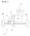
- a vehicle M includes a control apparatus (ECU) 10, an engine 11, a clutch 12, an automated transmission 13, a differential apparatus 14, a motor generator 15 and driving wheels (left and right front wheels) Wfl, Wfr.
- the engine 11 generates drive power by combusting fuel. It is configured so that the drive power of the engine 11 is transmitted to the driving wheels Wfl, Wfr via the clutch 12, the automated transmission 13 and the differential apparatus 14, that is, the vehicle M is a so-called front wheel drive vehicle.
- the clutch 12 is provided between a drive shaft 9 of the engine 11 and an input shaft 24 of the automated transmission 13.
- the clutch 12 is configured to connect and disconnect between the drive shaft 9 and the input shaft automatically by means of a clutch actuator according to a command of the control apparatus 10.
- the automated transmission 13 is an AMT (Automated Manual Transmission) which includes therein a dog clutch mechanism that will be described below, and automatically selects, for example, five forward gears and one backward gear.
- the differential apparatus 14 includes a final gear and a differential gear, and is formed integrally with the automated transmission 13.
- the differential apparatus 14 transmits a rotational torque inputted from at least one of an output shaft of the automated transmission 13 and the motor generator 15 to the driving wheels Wfl, Wfr in a manner that differential effects may be obtained.
- the motor generator 15 operates as a drive source (a motor) for supplying the rotational torque to the driving wheels Wfl, Wfr and operates also as an electric generator for converting kinetic energy of the vehicle to electric power.
- the motor generator 15 includes a stator fixedly provided at a case and a rotor provided at an inner circumferential-side relative to the stator so as to be rotatable.
- the automated transmission 13 includes a casing 22, the input shaft (i.e., a rotary shaft) 24, a first input gear 26, a second input gear 28, a third clutch ring (a third input gear) 30, a fourth clutch ring (a fourth input gear) 32, a clutch hub (i.e., a hub) 34, a sleeve 36, a stroke position sensor 38 (which corresponds to a disengagement detecting portion), an axial driving device 40, an output shaft 42, a first clutch ring (a first output gear) 44, a second clutch ring (a second output gear) 46, a third output gear 48 and a fourth output gear 50.
- a first dog clutch mechanism i.e., a dog clutch mechanism
- a second dog clutch mechanism is formed by, for example, the third clutch ring (the third input gear) 30, the fourth clutch ring (the fourth input gear) 32, the clutch hub (the hub) 34, the sleeve 36, the stroke position sensor 38 and the axial driving device 40.
- the dog clutch control apparatus for the automated transmission is formed by, for example, the first and second dog clutch mechanisms and the control apparatus 10.
- the first clutch ring 44, the second clutch ring 46, the third clutch ring 30 and the fourth clutch ring 32 serve as the clutch rings of this disclosure.
- the casing 22 of the automated transmission 13 includes a main body 22a formed in a substantially closed-end cylindrical configuration, a first wall 22b which corresponds to a bottom wall of the main body 22a and a second wall 22c dividing inside of the main body 22a in the right and left direction when viewed in Fig. 2 .
- the input shaft 24 is rotatably supported at the casing 22. Specifically, a first end (the left end when viewed in Fig. 2 ) of the input shaft 24 is supported at the first wall 22b via a bearing 22b1 and a second end side (the right end when viewed in Fig. 2 ) of the input shaft 24 is supported at the second wall 22c via a bearing 22c1.
- the second end of the input shaft 24 is rotatably connected to the drive shaft 9 of the engine 11 via the clutch 12.
- output of the engine 11 is inputted to the input shaft 24 in a case where the clutch 12 is connected.
- the input shaft 24 serves as the rotary shaft of this disclosure.
- the input shaft (rotary shaft) 24 of this disclosure is rotatably connected directly to the input shaft of the automated transmission 13 and is supported to be rotatable about a rotational axis (i.e., an axis) CL.
- the first input gear 26, the second input gear 28, the third clutch ring (the third input gear) 30, the fourth clutch ring (the fourth input gear) 32 are provided.
- the first and second input gears 26 and 28 are fixed to the input shaft 24 by, for example, spline-fitting, so as not to be rotatable relative to the input shaft 24.
- the third input gear is formed at an outer periphery of the third clutch ring 30 which is supported at the input shaft 24 to be rotatable relative to the input shaft 24.
- the fourth input gear is formed at an outer periphery of the fourth clutch ring 32 which is supported at the input shaft 24 to be rotatable relative to the input shaft 24.
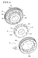
- the clutch hub (the hub) 34 is fixed to the input shaft 24 by, for example, spline-fitting so as not to be rotatable relative to the input shaft 24 in a manner that the clutch hub 34 is disposed between the third clutch ring 30 and the fourth clutch ring 32, and in a manner that the clutch hub 34 is arranged next to or adjacent to the third clutch ring 30 and to the fourth clutch ring 32 (refer to Fig. 4 ).
- the third input gear (the third clutch ring) 30 meshes with the third output gear which will be described below and the fourth input gear (the fourth clutch ring) 32 meshes with the fourth output gear which will be described below.
- the output shaft 42 is provided at the casing 22 to be arranged parallel to the input shaft 24.
- the output shaft 42 is rotatably supported at the casing 22. Specifically, a first end (the left end when viewed in Fig. 2 ) of the output shaft 42 is supported at the first wall 22b via a bearing 22b2 and a second end (the right end when viewed in Fig. 2 ) of the output shaft 42 is supported at the second wall 22c via a bearing 22c2.
- the first clutch ring (the first output gear) 44, the second clutch ring (the second output gear) 46, the third output gear 48, the fourth output gear 50 and a fifth output gear 52 are provided.
- the first clutch ring (the first output gear) 44 meshes with the first input gear 26, and a helical gear meshing with the first input gear 26 is formed at an outer circumferential surface of the first clutch ring 44.
- the second clutch ring (the second output gear) 46 meshes with the second input gear 28, and a helical gear meshing with the second input gear 28 is formed at an outer circumferential surface of the second clutch ring 46.
- the third output gear 48 meshes with the third clutch ring (the third input gear) 30, and a helical gear meshing with the third clutch ring (the third input gear) 30 is formed at an outer circumferential surface of the third output gear 48.
- the fourth output gear 50 meshes with the fourth clutch ring (the fourth input gear) 32, and a helical gear meshing with the fourth clutch ring (the fourth input gear) 32 is formed at an outer circumferential surface of the fourth output gear 50.
- the fifth output gear 52 meshes with an input gear of the differential apparatus 14, and a helical gear meshing with the input gear of the differential apparatus 14 is formed at an outer circumferential surface of the fifth output gear 52.
- the clutch hub (the hub) 34 is fixed to the output shaft 42 by, for example, spline-fitting.
- the clutch hub 34 is disposed between the first clutch ring 44 and the second clutch ring 46 to be arranged next to or adjacent to the first clutch ring 44 and to the second clutch ring 46.
- the configurations of the first clutch ring 44, the second clutch ring 46, the clutch hub 34 and the like are identical to those of the third clutch ring 30, the fourth clutch ring 32 and the clutch hub 34 at the input shaft 24, therefore the explanation will be omitted.
- the third output gear 48, the fourth output gear 50 and the fifth output gear 52 are fixed to the output shaft 42 by, for example, spline-fitting.
- the drive power of the engine 11 is inputted from the input shaft 24, is transmitted to the output shaft 42, and is finally outputted to the differential apparatus 14 via the fifth output gear 52.
- a configuration of the second dog clutch mechanism at the input shaft 24 is identical to that of the first dog clutch mechanism at the output shaft 42, and therefore an explanation will be made on the second dog clutch mechanism at the input shaft 24.
- the clutch hub 34 is supported at the input shaft 24 by spline-fitting so as to be rotatable integrally with the input shaft 24. As illustrated in Figs. 4 and 6 , the clutch hub 34 includes an engagement hole which is spline-fitted to the input shaft 24.
- the clutch hub 34 is formed in a flat cylindrical shape and includes spline teeth 34a provided at an outer circumferential surface of the clutch hub 34. For example, twelve of the spline teeth 34a are arranged in a circumferential direction of the clutch hub 34 at a constant pitch. Each of the spline teeth 34a is formed to include the same diameter of an addendum circle.
- a pair of spline teeth 34a that face each other in a radial direction across a center of the clutch hub 34 is formed to include the same small diameter of a dedendum circle (deep grooves 34a1).
- Each of the other ten spline teeth 34a is formed to include the same large diameter of a dedendum circle (shallow grooves 34a2) which is slightly larger than the small diameter of the dedendum circle of the pair of spline teeth 34a.
- Inner teeth 36a (i.e., a spline) of the sleeve 36 are brought in engagement with the spline teeth 34a of the clutch hub 34 to be slidable.
- the sleeve 36 is formed in a substantially annular configuration.
- An outer circumferential groove 36b which slidably meshes with a fork 40a of the axial driving device 40 (refer to Fig. 2 ) is provided at an outer periphery of the sleeve 36 in a circumferential direction of the sleeve 36.
- twelve of the inner teeth 36a provided at an inner periphery of the sleeve 36 are arranged in the circumferential direction at a constant pitch.
- Each of the inner teeth 36a is formed to include the same diameter of a dedendum circle.
- the inner teeth 36a include high teeth 36a1 and low teeth 36a2, and a height (a length in a radial direction) of each of the high teeth 36a1 differs from a height of each of the low teeth 36a2.
- the high teeth 36a1, each of which includes a higher height than each of the low teeth 36a2, are formed as a pair on the circumference so as to face each other at a 180 degree interval therebetween.
- the other inner teeth 36a, that is, the ten low teeth 36a2 include the same height which is shorter than the height of each of the high teeth 36a1.
- the sleeve 36 includes end surfaces (front end surfaces 36a4) which face the third and fourth clutch rings 30 and 32, respectively.
- Each of the front end surfaces 36a4 that is, a surface of each of the high teeth 36a1 and the low teeth 36a2 which is at a right angle relative to the rotational axis CL, includes a corner located at a front portion and a rear portion of each of the end surfaces 36a4 in a rotation direction.
- the corner includes a chamfered surface 36a3 which is formed at 45 degrees angle relative to the rotation direction (refer to Fig. 7 ).
- a tooth groove 36a5 is formed between each of the high teeth 36a1 and the low teeth 36a2 adjacent thereto, and between each of the low teeth 36a2 and the low teeth 36a2 adjacent thereto.
- Clutch front teeth 30b1 and clutch rear teeth 30b2, which will be described below, of the third clutch ring 30 fit or mate with the tooth grooves 36a5.
- the high teeth 36a1 of the sleeve 36 engage at a position corresponding to the small diameter of the dedendum circle (the deep grooves 34a1) of the clutch hub 34 and the low teeth 36a2 of the sleeve 36 engage at a position corresponding to the slightly large diameter of the dedendum circle (the shallow grooves 34a2) of the clutch hub 34.
- the third clutch ring 30 including a third dog clutch portion 30a (i.e., a dog clutch portion) and the fourth clutch ring 32 including a fourth dog clutch portion 32a (i.e., the dog clutch portion) are provided to be adjacent to the clutch hub 34 in the direction of the rotational axis CL, that is, the third clutch ring 30 and the fourth clutch ring 32 are arranged at the respective sides of the clutch hub 34.
- the third clutch ring 30 and the fourth clutch ring 32 are formed to be substantially symmetrical to each other relative to the clutch hub 34 disposed therebetween, therefore the explanation will be made on the third clutch ring 30.
- the third clutch ring 30 is provided at the input shaft 24 via a bearing so as to be rotatable relative to the input shaft 24 and so as not to be relatively movable in a direction of the rotational axis CL relative to the input shaft 24.
- the third input gear provided at an outer circumferential surface of the third clutch ring 30 forms an idler gear which is rotatable relative to the input shaft 24.
- the third dog clutch portion 30a is formed in a ring shape and is provided at a surface (a meshing portion or a mating portion) of the third clutch ring 30. The surface, at which the third dog clutch portion 30a is provided, faces the clutch hub 34.
- the dog clutch teeth 30b mesh with the inner teeth 36a of the sleeve 36 are provided at an outer periphery of the third dog clutch portion 30a.
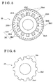
- the dog clutch teeth 30b include two kinds of clutch teeth having different heights or depths from each other, that is, the clutch front tooth 30b1 and the clutch rear tooth 30b2.
- the dog clutch teeth 30b are arranged in a circumferential direction of the third clutch ring 30 at a constant pitch.
- Each of the dog clutch teeth 30b is formed to include the same diameter of a dedendum circle.
- the clutch front tooth 30b1 is formed at two positions as a pair. That is, one of the positions of the clutch front teeth 30b1 is rotated from the other position by 180 degrees in the circumferential direction.
- the clutch front teeth 30b1 are formed in such a manner that an outer diameter of an addendum circle of the clutch front teeth 30b1 is larger than an inner diameter of an addendum circle of the high teeth 36a1 of the sleeve 36 and is smaller than an inner diameter of an addendum circle of the low teeth 36a2 of the sleeve 36.
- Each of the clutch front teeth 30b1 is formed to be extended in the direction of the rotational axis CL from a front end surface FE of the third dog clutch portion 30a, which constitutes the meshing portion, to a rear end position RE of the third dog clutch portion 30a.
- Each of the clutch front teeth 30b1 includes lateral surfaces 30b9 positioned at a side toward the sleeve 36.
- Each of the lateral surface 30b9 is provided with a chamfered portion 30b3 inclined by 45 degrees angle relative to a rotation direction of the third clutch ring 30.
- the clutch front teeth 30b1 are brought to engage with the high teeth 36a1 of the sleeve 36 without engaging with the low teeth 36a2.
- a front end portion of each of the clutch front teeth 30b1 is formed by a front end surface 30b5, which faces towards the sleeve 36, of the clutch front tooth 30b1 and by the chamfered portions 30b3.
- the clutch rear teeth 30b2 are arranged at a phase position between the two clutch front teeth 30b1 and another five of the clutch rear teeth 30b2 are arranged at a phase position between the two clutch front teeth 30b1, that is, ten of the clutch rear teeth 30b2 are provided in total.
- the clutch rear teeth 30b2 are formed in such a manner that an outer diameter of an addendum circle of the clutch rear teeth 30b2 is larger than the inner diameter of the addendum circle of the low teeth 36a2 of the sleeve 36.
- Each of the clutch rear teeth 30b2 is formed to be extended from a position retracted from the front end surface FE, that is, retracted from the side of the sleeve 36, by a predetermined amount t in the direction of the rotational axis CL, to the rear end position RE of the third dog clutch portion 30a.
- the front end surface FE of the third dog clutch portion 30a corresponds to the meshing portion.
- Each of the clutch rear teeth 30b2 includes lateral surfaces 30b7 positioned at a side towards the sleeve 36.
- Each of the lateral surfaces 30b7 is provided with chamfered portions 30b4 each inclined by 45 degrees angle relative to the rotation direction.
- each of the clutch rear teeth 30b2 is formed by a front end surface 30b6, which faces towards the sleeve 36, of the clutch rear tooth 30b2 and by the chamfered portions 30b4.
- a position sensor from among a variety of sensor types, including, but not limited to, a position sensitive detector or a linear encoder, may be used.
- the control apparatus 10 includes an integrated control apparatus for controlling an overall running state of the vehicle, an engine ECU for controlling the rotational torque of the engine and the number of rotations of the engine, a transmission ECU (a TM-ECU) for controlling a shifting operation of the automated transmission, a motor generator ECU for controlling rotational torque of the motor generator and a battery ECU for controlling supply of electric power, each of which includes a storage portion, a calculation portion and a control portion.
- the control apparatus (the TM-ECU) 10 controls a thrust load value of a linear actuator driving the axial driving device 40 and the control apparatus 10 controls a moving position of the front end surfaces 36a4 of the high teeth 36a1 on the basis of relative position signals detected by the stroke position sensor 38.
- the relative position signals indicate a relative position of a distal end (the front end surfaces 36a4 of the high teeth 36a1) of the sleeve 36 relative to the front end surface FE of the third dog clutch portion 30a, a relative position of the distal end of the sleeve 36 relative to the front end portions of the clutch rear teeth 30b2 and a relative position of the distal end of the sleeve 36 relative to the rear end position RE of the third dog clutch portion 30a, respectively.
- the axial driving device 40 reciprocates the sleeve 36 along the axial direction, that is, the sleeve 36 performs the axial movement.
- the axial driving device 40 allows the sleeve 36 to be moved by the reaction force.
- the axial driving device 40 includes the fork 40a, a fork shaft 40b and a drive device 40c.
- a distal end portion of the fork 40a is formed to match a shape of an outer circumferential configuration of the outer circumferential groove 36b of the sleeve 36.
- a base end portion of the fork 40a is fixed to the fork shaft 40b.
- the fork shaft 40b is supported at the casing 22 to be slidable along the axial direction. Specifically, a first end (the left end when viewed in Fig. 2 ) of the fork shaft 40b is supported at the first wall 22b via a bearing 22b3 and a second end side (the right end when viewed in Fig.
- the axial driving device 40 includes, for example, the fork 40a, the fork shaft 40b, a detent mechanism 58 and the drive device 40c (the linear actuator).
- the fork shaft 40b includes a stopper 58a and the stopper 58a is fitted, by a spring force, into a triangular groove 59 provided at the fork shaft 40b. Accordingly, the fork shaft 40b is configured so that a sliding position of the fork shaft 40b in the direction of the rotational axis is set.
- the drive device 40c is a linear drive apparatus of which drive source is the linear actuator.
- the linear drive apparatus includes, but not limited to, a linear actuator of a ball screw type.
- the ball screw type linear actuator includes, for example, a casing, a rotor, a driving shaft 40h (a ball screw shaft) and the nut member 40f.
- the casing is formed in a cylindrical shape and includes plural coils arranged in an inner circumferential direction as a stator.
- the rotor is arranged to be rotatable relative to the stator, and includes plural north pole magnets and south pole magnets. The north pole magnets and the south pole magnets face the stator with a magnetic gap provided between the magnets and the stator, and are arranged at an outer circumference to alternate with each other.
- the driving shaft 40h rotates about a rotational axis of the stator integrally with the rotor.
- the nut member 40f includes a ball nut which threadedly engages with the driving shaft 40h.
- the driving shaft 40h is screwed into the nut member 40f to be rotatable relative to the nut member 40f via plural balls.
- the driving shaft 40h is supported at the second wall 22c via a bearing 22c3. As electrification to each of the coils of the stator is controlled, the driving shaft 40h rotates in the forward direction and the backward direction arbitrarily, thereby reciprocating the nut member 40f and the fork shaft 40b, and positioning and retaining the nut member 40f and the fork shaft 40b at arbitrary positions.
- the axial driving device 40 allows the sleeve 36 to be moved by the reaction force which is applied from the third clutch ring 30 or the fourth clutch ring 32 in a case such a reaction force is applied to the sleeve 36.
- the linear actuator of the ball screw type is used as the drive device 40c in this embodiment, however, other drive device, including, but not limited to, a solenoid drive device or a hydraulic drive device may be used as long as the drive device allows the sleeve 36 to be moved by the reaction force which is applied from the third clutch ring 30 or the fourth clutch ring 32 in a case where the sleeve 36 is pushed against the third clutch ring 30 or the fourth clutch ring 32.
- the inner teeth 36a of the sleeve 36 are in an engaged state where the inner teeth 36a are engaged with the third dog clutch portion 30a of the third clutch ring 30 (refer to Fig. 10 ).
- the running state of the vehicle exceeds, for example, a speed change diagram which indicates a relationship between a throttle opening and a vehicle speed, and it is determined that the control apparatus 10 has received a shift instruction (refer to Fig.
- Step 101 for shifting from, for example, the third speed to the fourth speed (Step 101, which will be hereinafter referred to as S101)
- the control apparatus 10 controls or causes the axial driving device 40 to move the sleeve 36 in a direction of a neutral position at which the engagement between the sleeve 36 and the third clutch ring 30 is disengaged or released.
- the disengagement detecting portion detects a relative position of the high teeth 36a1 of the sleeve 36 relative to the dog clutch teeth 30b of the third clutch ring 30 as a stroke position (refer to Fig. 12 ).
- a time point of the shift instruction of the control apparatus 10 the stroke position of the sleeve 36 relative to the third clutch ring 30, a change in a gear ratio of the number of rotations of the input shaft 24 of the automated transmission 13 relative to the number of rotations of the output shaft 42 of the automated transmission 13, and a shift start determination time point are represented on the timing chart.
- the control apparatus 10 controls a fuel injection apparatus to reduce driving of the engine 11 and to reduce the rotational torque of the engine.
- the axial driving device 40 starts to move the sleeve 36 from the engaged state in which the inner teeth 36a of the sleeve 36 and the dog clutch teeth 30b of the third clutch ring 30 are engaged with each other to the neutral position at which the engagement between the inner teeth 36a and the dog clutch teeth 30b is released.
- the engagement is released when the stroke position of the high teeth 36a1 of the sleeve 36 is at a point S (that is, T1 in Figs. 12 and 13 ).
- the stroke position sensor 38 detects a time point at which the point S is reached, as the shift start determination time point.
- the start of the shifting operation is determined at the time point when the gear ratio, which decrease at a time of shifting operation, reaches a position at which the gear ratio comes to be a predetermined gear ratio, that is, a point G.
- the start of the shifting operation is determined at the point S, and therefore a shift-related control for engaging the next sleeve 36, that is, the sleeve 36 for performing the gear change to the next speed, with the fourth clutch ring 32 is executed at an early stage.
- the stroke position sensor 38 detects a position at which the high teeth 36a1 disengage from the clutch front tooth 30b1 of the third clutch ring 30 (refer to Fig. 11 , the point S in Fig. 12 ), the stroke position sensor 38 transmits a disengagement signal to the control apparatus 10 (S102).
- the control apparatus 10 Upon receiving the disengagement signal, the control apparatus 10 turns on a shift start determination flag (S103), and starts a shift start control (refer to Fig. 9 ). For example, as the shift start control, the control apparatus 10 controls the rotational torque of the engine, a transfer torque of the clutch and the rotational torque of the motor generator, as will be described below.
- the control apparatus 10 confirms whether the shift start determination flag is ON (S201). In a case where the shift start determination flag is not ON, the control apparatus 10 repeats the inquiry of whether the shift start determination flag is ON. In a case where it is determined that the shift start determination flag is ON, the control apparatus 10 controls the fuel injection apparatus to stop and the drive of the engine 11 to stop, and thereby controls the rotational torque of the engine to be reduced (start of an engine torque control, S202, T1 in Fig. 13 ). Accordingly, the drive of the engine 11 stops, and as illustrated at 1 in Fig. 13 , the rotational torque of the engine 11 in a positive direction further decreases and then changes to the rotational torque in a negative direction.
- the negative torque which is a friction torque of the engine 11, is inputted via the clutch 12 to the input shaft 24.
- the control apparatus 10 starts the control which increases the rotational torque of the motor generator 15 (start of a motor torque control, S203, and 2 in Fig. 13 ).
- the rotational torque of the motor generator 15 is controlled to supplement or compensate a loss of the rotational torque of the engine 11 which is inputted to a ring gear of the differential apparatus 14.
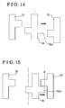
- the control apparatus 10 controls the axial driving device 40 to move the sleeve 36 to the neutral position (refer to Fig. 14 ).
- the control apparatus 10 drives the clutch actuator and reduces the transfer torque of the clutch 12 to be lower than the transfer torque at a full engagement and to be larger than 0 (4 in Fig. 13 ).
- the control apparatus 10 controls the clutch 12 to be in a half-engaged state (start of a clutch torque control, S204, T2 in Fig. 13 ). Because the input shaft 24 is not rotatably connected to the output shaft 42, rotational moment is generated only at part of the members which rotate integrally with the input shaft 24, that is, the rotational moment is generated at, for example, the input shaft 24, a clutch disc and the dog clutch.
- control apparatus 10 determines that the rotational speed of the input shaft 24 has decreased and is lower than a reference rotational speed
- the control apparatus 10 controls the transfer torque of the clutch 12 to be 0 (5 in Fig. 13 ) by driving the clutch actuator, and thus the clutch 12 is disengaged (T3 in Fig. 13 ).
- the control apparatus 10 determines whether the rotational seed of the input shaft 24 has decreased to a synchronizing rotational speed. In a case where the shift start determination flag is ON, the control apparatus 10 controls the axial driving device 40 to be driven to operate toward an up-shift-side, and thus starts the engagement of the sleeve 36 with the fourth clutch ring 32 (T4 in Fig. 13 ). The sleeve 36 moves from the neutral position illustrated in Fig. 14 towards the fourth clutch ring 32 as illustrated in Fig. 15 .
- the stroke position sensor 38 It is detected by the stroke position sensor 38 whether or not the high teeth 36a1 (an in-side sleeve), which face the fourth clutch ring 32, of the sleeve 36 have passed a position (a point K, that is, an end position).
- the point K is a position that is advanced from an end surface of each of front teeth of the fourth clutch ring 32 by a predetermined amount (refer to Figs. 15 and 16 ).
- the end position K is set at the position at which the engagement between the sleeve and the fourth clutch ring 32 is not released even in a case where the rotational torque from, for example, the engine 11 is applied.
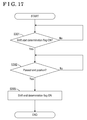
- control apparatus 10 In a case where the control apparatus 10 receives a detection signal that indicates that the high teeth 36a1 have passed the end position K (S302), the control apparatus 10 turns a shift end determination flag ON (S303).
- the control apparatus 10 confirms that the shift end determination flag is ON (S401)
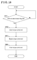
- the control apparatus 10 ends the shift-related control (S402, T5 in Fig. 13 ).
- the axial driving device 40 pushes the sleeve 36 against the fourth clutch ring 32 and moves the sleeve 36 forward until the high teeth 36a1 of the sleeve 36 come to fully engage with clutch front teeth and clutch rear teeth of the fourth clutch ring 32.
- the control apparatus 10 controls the transfer torque of the clutch 12 to be increased gradually until the transfer torque at the full engagement is reached (6 in Fig. 13 ).
- the clutch torque control ends (S402).
- the control apparatus 10 controls the engine 11 to start and controls the rotational torque of the engine 11 to increase (7 in Fig. 13 ). At the same time, the control apparatus 10 transmits a control signal to the motor generator 15, and decreases the rotational torque of the motor generator 15 (8 in Fig. 13 ).
- the rotational speed of the sleeve 36 is increased.
- the relative rotation that is, the speed of the relative rotation, between the sleeve 36 and the third clutch ring 30 is in a manner opposite to the up-shift operation as explained above.
- the tooth groove of the clutch front teeth 30b1 in which the corresponding high tooth 36a1 fits or engages is the tooth groove that is positioned at an opposite side relative to the clutch front tooth 30b1 in the circumferential direction.
- the other operation is identical to that in the case where the rotational speed of the sleeve 36 is reduced.
- the control apparatus 10 starts the shift-related control, that is, the control related to or associated with the shifting, for engaging the dog clutch mechanism 30, 36, 40 (the third clutch ring 30, the sleeve 36, the axial driving device 40) which is engaged at the time of shifting operation.
- the shift-related control is started at a time point earlier than a time point when the change occurs in the gear ratio due to the decrease in the number of rotations of the engine at the time of shifting operation. Consequently, the shift-related control is executed without delay, thereby enhancing drivability and preventing a gear shift shock from occurring.
- the engine torque control which controls the rotational torque of the engine 11
- the clutch torque control which controls the transfer torque of the clutch 12
- the motor torque control that is necessary to be conducted at the time of shifting operation is executed without delay, thereby preventing a torque loss or torque decrease at the time of shifting operation.
- the explanation is made on a case where the up-shift is performed from the third speed to the fourth speed, however, this embodiment is not limited thereto.
- This embodiment may be applied to a case where the down-shift is performed from, for example, the second speed to the first speed. Also in a case where the down-shift operation is performed, the shift-related control is started early, thereby enhancing the drivability and preventing the gear shift shock occurring at the shifting operation.
- This embodiment is applied to the hybrid vehicle on which the engine and the motor generator are mounted as the drive source, however, this embodiment may be applied to a vehicle whose drive source is only the engine.
- the motor torque control is not conducted, however, the control of the engine rotational torque needs to be conducted.
- a start determination time point at which the start of the shift-related control is determined may be advanced.
- the dog clutch mechanism is provided with the dog clutch teeth including the two tiers of teeth, that is, the front teeth and the rear teeth.
- the dog clutch teeth may include one tier of teeth, or three tiers of teeth, that is, the front teeth, the rear teeth, and intermediate teeth provided between the front teeth and the rear teeth.
- the two clutch front teeth are provided on the circumference so as to face each other.
- three or more than three clutch front teeth may be provided on the circumference of the clutch ring to be equally spaced from one another.
- the rotary shaft corresponds to the input shaft 24 of the automated transmission, which is rotatably connected to the output shaft 42 of the engine 11 via the clutch 12, however, the embodiment is not limited thereto.
- the rotary shaft may correspond to the output shaft transmitting the rotational torque from the automated transmission to a driving wheel-side.
- the automated transmission may include an input shaft connected to an output shaft of an engine via a clutch, a counter shaft which is arranged parallelly to the input shaft and is rotatably connected via transmission gear to the input shaft, a rotational axis which is parallel to the counter shaft, and an output shaft provided with plural idler gears which mesh with the plural transmission gears provided at the counter shaft, wherein the output shaft of the automated transmission may correspond to the rotary shaft.
- the moment of inertia is large at the sleeve-side, and the moment of inertia is small at the clutch ring-side (a free state).
- the rotary shaft which is rotatably connected to the input shaft of the automated transmission includes the rotary shaft (the input shaft) which is connected directly to the input shaft as described in this embodiment.
- the rotary shaft which is rotatably connected to the output shaft of the automated transmission includes the rotary shaft which is connected directly to the output shaft.
Landscapes
- Engineering & Computer Science (AREA)
- General Engineering & Computer Science (AREA)
- Mechanical Engineering (AREA)
- Physics & Mathematics (AREA)
- Fluid Mechanics (AREA)
- Control Of Transmission Device (AREA)
- Hydraulic Clutches, Magnetic Clutches, Fluid Clutches, And Fluid Joints (AREA)
- Hybrid Electric Vehicles (AREA)
- Electrical Control Of Air Or Fuel Supplied To Internal-Combustion Engine (AREA)
Abstract
Description
- This disclosure generally relates to a dog clutch control apparatus for an automated transmission.
- Conventionally, a powertrain of a vehicle includes a transmission which changes torque and/or the number of rotations of a driving apparatus including, for example, an engine and/or an electric motor, which is used for driving a driving wheel, so that the torque and/or rotations are transmitted to the driving wheel according to running conditions of the vehicle. There are some types of transmissions including, for example, a normally-meshed type transmission. A known normally-meshed type transmission includes plural idler gears, each of which meshes with a rotary shaft connected to the driving wheel to be rotatable relative to the rotary shaft and not to be movable in a direction of a rotational axis, and plural gears, which are provided around a periphery of a counter shaft arranged to be parallel to the rotary shaft. The idler gears and the gears normally mesh with each other. According to the known normally-engaged type transmission, a sleeve is spline-fitted to the rotary shaft to be movable in the direction of the rotational axis, and the sleeve is arranged side by side with the idler gear. Engaging teeth (the spline), which are provided at a joining surface of the sleeve which is joined to the idler gear, are brought to be engaged with engaged teeth (dog clutch teeth), which are provided at a joined surface of the idler gear. Thus, the idler gear engaged with the sleeve and the rotary shaft rotate integrally with each other. As the idler gear which rotates integrally with the rotary shaft and the gear of the counter shaft which meshes with the idler gear rotate in association with each other, torque and/or the number of rotations of the rotary shaft is transmitted to the counter shaft. A shifting operation is performed by selecting, from among the plural idler gears which include different numbers of teeth to each other, the idler gear that is to be rotated integrally with the rotary shaft and by bringing the sleeve into engagement with the selected idler gear.
- According to the known transmission, a shift instruction is present at a time of a shifting operation, however, the shifting operation is actually started thereafter and therefore time lag is generated. At the shifting operation, for example, an up-shift operation, the gear (spline) arranged at an input shaft-side is engaged with the gear (the dog clutch teeth) arranged at an output shaft when a rotational speed of the gear of the input shaft-side substantially coincides with a rotational speed of the gear of the output shaft. The gear arranged at the output shaft includes a high gear ratio and rotates at a low rotational speed in accordance with rotations of vehicle wheels. Accordingly, after the shifting operation starts, engine torque needs to be controlled to be reduced and/or a pressing torque of the clutch needs to be controlled, for example. However, these controls are executed in accordance with an actual start of the shifting operation, and therefore it is important at which point of time the start of the shifting operation is determined. According to disclosure related to
JPH7-167276A - However, according to a shift control method described in Patent reference 1, it is determined whether or not the shifting operation has actually started after the predetermined change occurs in the gear ratio value. The gear ratio is a ratio of the number of rotations of the input shaft driven by a drive shaft of an engine relative to the number of rotations of the output shaft driven by a rotation of the wheels. At the time of shifting operation, the shifting operation needs to wait to be performed until the number of rotations of the engine decreases. Therefore, the controls which are to be executed after the determination of the start of the shifting operation may be delayed, and as a result, drivability may be deteriorated and/or a gear shift shock may be generated due to the delay of the controls.
- A need thus exists for a dog clutch control apparatus for an automated transmission, at which start of a shifting operation is determined in accordance with a moving position of a dog clutch mechanism, and thus a shift start timing is determined earlier than a case where the shift start timing is determined in accordance with a change of a gear ratio, and at which control after the shift start determination is executed without delay, and therefore drivability is enhanced and an occurrence of a shift shock is prevented.
- According to an aspect of this disclosure, a dog clutch control apparatus for an automated transmission includes a rotary shaft which is rotatably connected to one of an input shaft of an automated transmission and an output shaft of the automated transmission, and is supported to be rotatable about an axis, a plurality of dog clutch mechanisms which are engageable and disengageable, each of the dog clutch mechanisms includes a clutch ring which is rotatably supported at the rotary shaft and is rotatably connected to the other one of the input shaft and the output shaft at a predetermined gear ratio, each of the dog clutch mechanisms includes a clutch hub which is fixed to the rotary shaft and is arranged next to the clutch ring, each of the dog clutch mechanisms includes a sleeve which is provided with a spline and is fitted with the clutch hub by the spline to be movable in a direction of the axis, each of the dog clutch mechanisms includes a dog clutch portion which is provided at the clutch ring to protrude towards the sleeve and selectively meshes with the spline formed at the sleeve in response to an axial movement of the sleeve, each of the dog clutch mechanisms includes an axial driving device for moving the sleeve in the direction of the axis, a disengagement detecting portion for detecting disengagement of the sleeve from the clutch ring before the sleeve reaches a neutral position from an engaged state in which the sleeve engages with the clutch ring, and a control apparatus for controlling operation of the axial driving device, wherein in a case where the disengagement of the sleeve from the clutch ring is detected by the disengagement detecting portion at a time of shifting operation, the control apparatus starts a shift-related control for engaging the dog clutch mechanism which is engaged at the time of shifting operation.
- According to the above described configuration, in a case where the disengagement is detected by the disengagement detecting portion, the control apparatus starts the shift-related control for engaging the dog clutch mechanism which is engaged at the time of shifting operation. Accordingly, the shift-related control is started at a time point that is earlier than a time point when a change occurs to a gear ratio at shifting operation. Consequently, the shift-related control is executed without delay, thereby enhancing drivability and preventing gear shift shock from occurring.
- According to another aspect of this disclosure, the shift-related control includes an engine torque control for controlling a rotational torque of an engine which drives a wheel of a vehicle and a clutch torque control for controlling a transfer torque of a clutch.
- According to the above described configuration, the engine torque control, which controls the rotational torque of the engine, and the clutch torque control, which controls the transfer torque of the clutch, are executed without delay at the time shifting operation. Consequently, the drivability is enhanced and the gear shift shock is prevented from occurring.
- According to another aspect of this disclosure, the dog clutch control apparatus further includes a motor generator as a drive source which drives the wheel of the vehicle, wherein the shift-related control includes a motor torque control for preventing torque loss from occurring at the time of shifting operation.
- According to the above described configuration, on a hybrid vehicle on which the motor generator, in addition to the engine, is mounted as the drive source, the motor torque control that is necessary to be conducted at the time of shifting operation is executed without delay, thereby preventing a torque loss at the shifting operation.
- According to another aspect of this disclosure, the motor torque control controls a rotational torque of the motor generator to be increased at the same time as the rotational torque of the engine decreases.
- According to the above described configuration, on the hybrid vehicle on which the motor generator, together with the engine, is mounted as the drive source, the motor torque control that is necessary to be conducted at the time of shifting operation is executed without delay, thereby preventing the torque loss at the shifting operation.
- The foregoing and additional features and characteristics of this disclosure will become more apparent from the following detailed description considered with the reference to the accompanying drawings, wherein:
-
Fig. 1 is a schematic view of a vehicle mounted with an automated transmission including a dog clutch according to an embodiment disclosed here; -
Fig. 2 is a schematic diagram of the automated transmission including the dog clutch according to the embodiment; -
Fig. 3 is a block diagram of a control apparatus according to the embodiment; -
Fig. 4 is an exploded perspective view of a dog clutch mechanism according to the embodiment; -
Fig. 5 is a front view of a clutch ring according to the embodiment; -
Fig. 6 is a front view of a clutch hub according to the embodiment; -
Fig. 7 is a front view of a sleeve according to the embodiment; -
Fig. 8 is a flowchart illustrating a procedure for starting a shift-related control according to the embodiment; -
Fig. 9 is a flowchart illustrating the shift-related control; -
Fig. 10 is a view illustrating a positional relationship of a spline of the sleeve and a dog clutch tooth in an engaged state according to the embodiment; -
Fig. 11 is a view illustrating the positional relationship of the spline of the sleeve and the dog clutch tooth at a time when the engaged state is released; -
Fig. 12 is a diagram illustrating, in a time chart, a stroke position of the sleeve according to the embodiment; -
Fig. 13 is a diagram illustrating, in a time chart, the shift-related control; -
Fig. 14 is a view illustrating a state in which the sleeve is at a neutral position according to the embodiment; -
Fig. 15 is a view illustrating a state at the time point when the sleeve starts the engagement with a next dog clutch; -
Fig. 16 is a diagram illustrating, by the stroke position of the sleeve, a movement of the sleeve engaging with the next dog clutch; -
Fig. 17 is a view illustrating a flowchart for executing an end determination of the shift-related control; and -
Fig. 18 is a flowchart illustrating end of the shift-related control. - An embodiment, in which an automated transmission provided with a dog clutch control apparatus for an automated transmission is applied to a vehicle, will be explained with reference to the drawings.
- As illustrated in
Fig. 1 , a vehicle M includes a control apparatus (ECU) 10, anengine 11, aclutch 12, anautomated transmission 13, adifferential apparatus 14, amotor generator 15 and driving wheels (left and right front wheels) Wfl, Wfr. Theengine 11 generates drive power by combusting fuel. It is configured so that the drive power of theengine 11 is transmitted to the driving wheels Wfl, Wfr via theclutch 12, theautomated transmission 13 and thedifferential apparatus 14, that is, the vehicle M is a so-called front wheel drive vehicle. - The
clutch 12 is provided between a drive shaft 9 of theengine 11 and aninput shaft 24 of theautomated transmission 13. Theclutch 12 is configured to connect and disconnect between the drive shaft 9 and the input shaft automatically by means of a clutch actuator according to a command of thecontrol apparatus 10. Theautomated transmission 13 is an AMT (Automated Manual Transmission) which includes therein a dog clutch mechanism that will be described below, and automatically selects, for example, five forward gears and one backward gear. - The
differential apparatus 14 includes a final gear and a differential gear, and is formed integrally with theautomated transmission 13. Thedifferential apparatus 14 transmits a rotational torque inputted from at least one of an output shaft of the automatedtransmission 13 and themotor generator 15 to the driving wheels Wfl, Wfr in a manner that differential effects may be obtained. - The
motor generator 15 operates as a drive source (a motor) for supplying the rotational torque to the driving wheels Wfl, Wfr and operates also as an electric generator for converting kinetic energy of the vehicle to electric power. Themotor generator 15 includes a stator fixedly provided at a case and a rotor provided at an inner circumferential-side relative to the stator so as to be rotatable. - As illustrated in
Fig. 2 indicating part of a configuration of the automatedtransmission 13, theautomated transmission 13 includes acasing 22, the input shaft (i.e., a rotary shaft) 24, afirst input gear 26, asecond input gear 28, a third clutch ring (a third input gear) 30, a fourth clutch ring (a fourth input gear) 32, a clutch hub (i.e., a hub) 34, asleeve 36, a stroke position sensor 38 (which corresponds to a disengagement detecting portion), anaxial driving device 40, anoutput shaft 42, a first clutch ring (a first output gear) 44, a second clutch ring (a second output gear) 46, athird output gear 48 and afourth output gear 50. A first dog clutch mechanism (i.e., a dog clutch mechanism) is formed by, for example, the first clutch ring (the first output gear) 44, the second clutch ring (the second output gear) 46, the clutch hub (the hub) 34, thesleeve 36 and an axial driving device. A second dog clutch mechanism (i.e., the dog clutch mechanism) is formed by, for example, the third clutch ring (the third input gear) 30, the fourth clutch ring (the fourth input gear) 32, the clutch hub (the hub) 34, thesleeve 36, thestroke position sensor 38 and theaxial driving device 40. The dog clutch control apparatus for the automated transmission is formed by, for example, the first and second dog clutch mechanisms and thecontrol apparatus 10. The firstclutch ring 44, the secondclutch ring 46, the thirdclutch ring 30 and the fourthclutch ring 32 serve as the clutch rings of this disclosure. - The
casing 22 of the automatedtransmission 13 includes amain body 22a formed in a substantially closed-end cylindrical configuration, afirst wall 22b which corresponds to a bottom wall of themain body 22a and asecond wall 22c dividing inside of themain body 22a in the right and left direction when viewed inFig. 2 . - The
input shaft 24 is rotatably supported at thecasing 22. Specifically, a first end (the left end when viewed inFig. 2 ) of theinput shaft 24 is supported at thefirst wall 22b via a bearing 22b1 and a second end side (the right end when viewed inFig. 2 ) of theinput shaft 24 is supported at thesecond wall 22c via a bearing 22c1. The second end of theinput shaft 24 is rotatably connected to the drive shaft 9 of theengine 11 via the clutch 12. Thus, output of theengine 11 is inputted to theinput shaft 24 in a case where the clutch 12 is connected. Theinput shaft 24 serves as the rotary shaft of this disclosure. The input shaft (rotary shaft) 24 of this disclosure is rotatably connected directly to the input shaft of the automatedtransmission 13 and is supported to be rotatable about a rotational axis (i.e., an axis) CL. - At the
input shaft 24, thefirst input gear 26, thesecond input gear 28, the third clutch ring (the third input gear) 30, the fourth clutch ring (the fourth input gear) 32 are provided. The first and second input gears 26 and 28 are fixed to theinput shaft 24 by, for example, spline-fitting, so as not to be rotatable relative to theinput shaft 24. The third input gear is formed at an outer periphery of the thirdclutch ring 30 which is supported at theinput shaft 24 to be rotatable relative to theinput shaft 24. The fourth input gear is formed at an outer periphery of the fourthclutch ring 32 which is supported at theinput shaft 24 to be rotatable relative to theinput shaft 24. Further, the clutch hub (the hub) 34 is fixed to theinput shaft 24 by, for example, spline-fitting so as not to be rotatable relative to theinput shaft 24 in a manner that theclutch hub 34 is disposed between the thirdclutch ring 30 and the fourthclutch ring 32, and in a manner that theclutch hub 34 is arranged next to or adjacent to the thirdclutch ring 30 and to the fourth clutch ring 32 (refer toFig. 4 ). The third input gear (the third clutch ring) 30 meshes with the third output gear which will be described below and the fourth input gear (the fourth clutch ring) 32 meshes with the fourth output gear which will be described below. - The
output shaft 42 is provided at thecasing 22 to be arranged parallel to theinput shaft 24. Theoutput shaft 42 is rotatably supported at thecasing 22. Specifically, a first end (the left end when viewed inFig. 2 ) of theoutput shaft 42 is supported at thefirst wall 22b via a bearing 22b2 and a second end (the right end when viewed inFig. 2 ) of theoutput shaft 42 is supported at thesecond wall 22c via a bearing 22c2. - At the
output shaft 42, the first clutch ring (the first output gear) 44, the second clutch ring (the second output gear) 46, thethird output gear 48, thefourth output gear 50 and afifth output gear 52 are provided. The first clutch ring (the first output gear) 44 meshes with thefirst input gear 26, and a helical gear meshing with thefirst input gear 26 is formed at an outer circumferential surface of the firstclutch ring 44. The second clutch ring (the second output gear) 46 meshes with thesecond input gear 28, and a helical gear meshing with thesecond input gear 28 is formed at an outer circumferential surface of the secondclutch ring 46. Thethird output gear 48 meshes with the third clutch ring (the third input gear) 30, and a helical gear meshing with the third clutch ring (the third input gear) 30 is formed at an outer circumferential surface of thethird output gear 48. Thefourth output gear 50 meshes with the fourth clutch ring (the fourth input gear) 32, and a helical gear meshing with the fourth clutch ring (the fourth input gear) 32 is formed at an outer circumferential surface of thefourth output gear 50. Thefifth output gear 52 meshes with an input gear of thedifferential apparatus 14, and a helical gear meshing with the input gear of thedifferential apparatus 14 is formed at an outer circumferential surface of thefifth output gear 52. - The clutch hub (the hub) 34 is fixed to the
output shaft 42 by, for example, spline-fitting. Theclutch hub 34 is disposed between the firstclutch ring 44 and the secondclutch ring 46 to be arranged next to or adjacent to the firstclutch ring 44 and to the secondclutch ring 46. The configurations of the firstclutch ring 44, the secondclutch ring 46, theclutch hub 34 and the like are identical to those of the thirdclutch ring 30, the fourthclutch ring 32 and theclutch hub 34 at theinput shaft 24, therefore the explanation will be omitted. Thethird output gear 48, thefourth output gear 50 and thefifth output gear 52 are fixed to theoutput shaft 42 by, for example, spline-fitting. The drive power of theengine 11 is inputted from theinput shaft 24, is transmitted to theoutput shaft 42, and is finally outputted to thedifferential apparatus 14 via thefifth output gear 52. - A configuration of the second dog clutch mechanism at the
input shaft 24 is identical to that of the first dog clutch mechanism at theoutput shaft 42, and therefore an explanation will be made on the second dog clutch mechanism at theinput shaft 24. - The
clutch hub 34 is supported at theinput shaft 24 by spline-fitting so as to be rotatable integrally with theinput shaft 24. As illustrated inFigs. 4 and6 , theclutch hub 34 includes an engagement hole which is spline-fitted to theinput shaft 24. Theclutch hub 34 is formed in a flat cylindrical shape and includesspline teeth 34a provided at an outer circumferential surface of theclutch hub 34. For example, twelve of thespline teeth 34a are arranged in a circumferential direction of theclutch hub 34 at a constant pitch. Each of thespline teeth 34a is formed to include the same diameter of an addendum circle. Among the twelvespline teeth 34a, a pair ofspline teeth 34a that face each other in a radial direction across a center of theclutch hub 34 is formed to include the same small diameter of a dedendum circle (deep grooves 34a1). Each of the other tenspline teeth 34a is formed to include the same large diameter of a dedendum circle (shallow grooves 34a2) which is slightly larger than the small diameter of the dedendum circle of the pair ofspline teeth 34a.Inner teeth 36a (i.e., a spline) of thesleeve 36 are brought in engagement with thespline teeth 34a of theclutch hub 34 to be slidable. - The
sleeve 36 is formed in a substantially annular configuration. An outercircumferential groove 36b which slidably meshes with afork 40a of the axial driving device 40 (refer toFig. 2 ) is provided at an outer periphery of thesleeve 36 in a circumferential direction of thesleeve 36. As illustrated inFigs. 4 and7 , twelve of theinner teeth 36a provided at an inner periphery of thesleeve 36 are arranged in the circumferential direction at a constant pitch. Each of theinner teeth 36a is formed to include the same diameter of a dedendum circle. Theinner teeth 36a include high teeth 36a1 and low teeth 36a2, and a height (a length in a radial direction) of each of the high teeth 36a1 differs from a height of each of the low teeth 36a2. The high teeth 36a1, each of which includes a higher height than each of the low teeth 36a2, are formed as a pair on the circumference so as to face each other at a 180 degree interval therebetween. The otherinner teeth 36a, that is, the ten low teeth 36a2 include the same height which is shorter than the height of each of the high teeth 36a1. Thesleeve 36 includes end surfaces (front end surfaces 36a4) which face the third and fourth clutch rings 30 and 32, respectively. Each of the front end surfaces 36a4, that is, a surface of each of the high teeth 36a1 and the low teeth 36a2 which is at a right angle relative to the rotational axis CL, includes a corner located at a front portion and a rear portion of each of the end surfaces 36a4 in a rotation direction. The corner includes a chamfered surface 36a3 which is formed at 45 degrees angle relative to the rotation direction (refer toFig. 7 ). Thus, the corners are prevented from being damaged and/or chipped off due to an impact with dog clutch teeth, which will be described below, of the third and fourth clutch rings 30 and 32. A tooth groove 36a5 is formed between each of the high teeth 36a1 and the low teeth 36a2 adjacent thereto, and between each of the low teeth 36a2 and the low teeth 36a2 adjacent thereto. Clutch front teeth 30b1 and clutch rear teeth 30b2, which will be described below, of the thirdclutch ring 30 fit or mate with the tooth grooves 36a5. The high teeth 36a1 of thesleeve 36 engage at a position corresponding to the small diameter of the dedendum circle (the deep grooves 34a1) of theclutch hub 34 and the low teeth 36a2 of thesleeve 36 engage at a position corresponding to the slightly large diameter of the dedendum circle (the shallow grooves 34a2) of theclutch hub 34. - At the
input shaft 24, the thirdclutch ring 30 including a third dogclutch portion 30a (i.e., a dog clutch portion) and the fourthclutch ring 32 including a fourth dogclutch portion 32a (i.e., the dog clutch portion) are provided to be adjacent to theclutch hub 34 in the direction of the rotational axis CL, that is, the thirdclutch ring 30 and the fourthclutch ring 32 are arranged at the respective sides of theclutch hub 34. The thirdclutch ring 30 and the fourthclutch ring 32 are formed to be substantially symmetrical to each other relative to theclutch hub 34 disposed therebetween, therefore the explanation will be made on the thirdclutch ring 30. - As illustrated in
Figs. 4 and5 , the thirdclutch ring 30 is provided at theinput shaft 24 via a bearing so as to be rotatable relative to theinput shaft 24 and so as not to be relatively movable in a direction of the rotational axis CL relative to theinput shaft 24. The third input gear provided at an outer circumferential surface of the thirdclutch ring 30 forms an idler gear which is rotatable relative to theinput shaft 24. The third dogclutch portion 30a is formed in a ring shape and is provided at a surface (a meshing portion or a mating portion) of the thirdclutch ring 30. The surface, at which the third dogclutch portion 30a is provided, faces theclutch hub 34. Plural dogclutch teeth 30b mesh with theinner teeth 36a of thesleeve 36 are provided at an outer periphery of the third dogclutch portion 30a. The dogclutch teeth 30b include two kinds of clutch teeth having different heights or depths from each other, that is, the clutch front tooth 30b1 and the clutch rear tooth 30b2. In addition, the dogclutch teeth 30b are arranged in a circumferential direction of the thirdclutch ring 30 at a constant pitch. Each of the dogclutch teeth 30b is formed to include the same diameter of a dedendum circle. The clutch front tooth 30b1 is formed at two positions as a pair. That is, one of the positions of the clutch front teeth 30b1 is rotated from the other position by 180 degrees in the circumferential direction. The clutch front teeth 30b1 are formed in such a manner that an outer diameter of an addendum circle of the clutch front teeth 30b1 is larger than an inner diameter of an addendum circle of the high teeth 36a1 of thesleeve 36 and is smaller than an inner diameter of an addendum circle of the low teeth 36a2 of thesleeve 36. Each of the clutch front teeth 30b1 is formed to be extended in the direction of the rotational axis CL from a front end surface FE of the third dogclutch portion 30a, which constitutes the meshing portion, to a rear end position RE of the third dogclutch portion 30a. Each of the clutch front teeth 30b1 includes lateral surfaces 30b9 positioned at a side toward thesleeve 36. Each of the lateral surface 30b9 is provided with a chamfered portion 30b3 inclined by 45 degrees angle relative to a rotation direction of the thirdclutch ring 30. In a case where thesleeve 36 comes closer to the thirdclutch ring 30 while rotating relative to the thirdclutch ring 30, the clutch front teeth 30b1 are brought to engage with the high teeth 36a1 of thesleeve 36 without engaging with the low teeth 36a2. A front end portion of each of the clutch front teeth 30b1 is formed by a front end surface 30b5, which faces towards thesleeve 36, of the clutch front tooth 30b1 and by the chamfered portions 30b3. - As illustrated in
Figs. 4 and5 , five of the clutch rear teeth 30b2 are arranged at a phase position between the two clutch front teeth 30b1 and another five of the clutch rear teeth 30b2 are arranged at a phase position between the two clutch front teeth 30b1, that is, ten of the clutch rear teeth 30b2 are provided in total. The clutch rear teeth 30b2 are formed in such a manner that an outer diameter of an addendum circle of the clutch rear teeth 30b2 is larger than the inner diameter of the addendum circle of the low teeth 36a2 of thesleeve 36. Each of the clutch rear teeth 30b2 is formed to be extended from a position retracted from the front end surface FE, that is, retracted from the side of thesleeve 36, by a predetermined amount t in the direction of the rotational axis CL, to the rear end position RE of the third dogclutch portion 30a. The front end surface FE of the third dogclutch portion 30a corresponds to the meshing portion. Each of the clutch rear teeth 30b2 includes lateral surfaces 30b7 positioned at a side towards thesleeve 36. Each of the lateral surfaces 30b7 is provided with chamfered portions 30b4 each inclined by 45 degrees angle relative to the rotation direction. In a case where thesleeve 36 comes closer to the thirdclutch ring 30 while rotating relative to the thirdclutch ring 30, as the high teeth 36a1 and the low teeth 36a2 move into the position of the thirdclutch ring 30, the position which is retracted by the predetermined amount t, the clutch rear teeth 30b2 engage with the high teeth 36a1 and the low teeth 36a2 of thesleeve 36. Because the clutch rear teeth 30b2 engage with the high teeth 36a1 and the low teeth 36a2 of thesleeve 36, a large rotational torque is transmitted safely and reliably. A front end portion of each of the clutch rear teeth 30b2 is formed by a front end surface 30b6, which faces towards thesleeve 36, of the clutch rear tooth 30b2 and by the chamfered portions 30b4. - As the
stroke position sensor 38, a position sensor from among a variety of sensor types, including, but not limited to, a position sensitive detector or a linear encoder, may be used. - The
control apparatus 10 includes an integrated control apparatus for controlling an overall running state of the vehicle, an engine ECU for controlling the rotational torque of the engine and the number of rotations of the engine, a transmission ECU (a TM-ECU) for controlling a shifting operation of the automated transmission, a motor generator ECU for controlling rotational torque of the motor generator and a battery ECU for controlling supply of electric power, each of which includes a storage portion, a calculation portion and a control portion. In addition, as illustrated inFig. 3 , the control apparatus (the TM-ECU) 10 controls a thrust load value of a linear actuator driving theaxial driving device 40 and thecontrol apparatus 10 controls a moving position of the front end surfaces 36a4 of the high teeth 36a1 on the basis of relative position signals detected by thestroke position sensor 38. The relative position signals indicate a relative position of a distal end (the front end surfaces 36a4 of the high teeth 36a1) of thesleeve 36 relative to the front end surface FE of the third dogclutch portion 30a, a relative position of the distal end of thesleeve 36 relative to the front end portions of the clutch rear teeth 30b2 and a relative position of the distal end of thesleeve 36 relative to the rear end position RE of the third dogclutch portion 30a, respectively. - The
axial driving device 40 reciprocates thesleeve 36 along the axial direction, that is, thesleeve 36 performs the axial movement. In a case where thesleeve 36 is pressed or pushed against the thirdclutch ring 30 or the fourthclutch ring 32 and when a reaction force is applied from the thirdclutch ring 30 or the fourthclutch ring 32, theaxial driving device 40 allows thesleeve 36 to be moved by the reaction force. - The
axial driving device 40 includes thefork 40a, afork shaft 40b and adrive device 40c. A distal end portion of thefork 40a is formed to match a shape of an outer circumferential configuration of the outercircumferential groove 36b of thesleeve 36. A base end portion of thefork 40a is fixed to thefork shaft 40b. Thefork shaft 40b is supported at thecasing 22 to be slidable along the axial direction. Specifically, a first end (the left end when viewed inFig. 2 ) of thefork shaft 40b is supported at thefirst wall 22b via a bearing 22b3 and a second end side (the right end when viewed inFig. 2 ) of thefork shaft 40b is fixed at abracket 40d. Thebracket 40d is slidably supported by a guide member (a rotation lock) 40e which protrudes in the axial direction from thesecond wall 22c and thebracket 40d is fixed to anut member 40f, which will be described below, so as not to be rotatable relative thereto. Theaxial driving device 40 includes, for example, thefork 40a, thefork shaft 40b, adetent mechanism 58 and thedrive device 40c (the linear actuator). Thefork shaft 40b includes astopper 58a and thestopper 58a is fitted, by a spring force, into atriangular groove 59 provided at thefork shaft 40b. Accordingly, thefork shaft 40b is configured so that a sliding position of thefork shaft 40b in the direction of the rotational axis is set. - The
drive device 40c is a linear drive apparatus of which drive source is the linear actuator. The linear drive apparatus includes, but not limited to, a linear actuator of a ball screw type. The ball screw type linear actuator includes, for example, a casing, a rotor, a drivingshaft 40h (a ball screw shaft) and thenut member 40f. The casing is formed in a cylindrical shape and includes plural coils arranged in an inner circumferential direction as a stator. The rotor is arranged to be rotatable relative to the stator, and includes plural north pole magnets and south pole magnets. The north pole magnets and the south pole magnets face the stator with a magnetic gap provided between the magnets and the stator, and are arranged at an outer circumference to alternate with each other. The drivingshaft 40h rotates about a rotational axis of the stator integrally with the rotor. Thenut member 40f includes a ball nut which threadedly engages with the drivingshaft 40h. The drivingshaft 40h is screwed into thenut member 40f to be rotatable relative to thenut member 40f via plural balls. The drivingshaft 40h is supported at thesecond wall 22c via a bearing 22c3. As electrification to each of the coils of the stator is controlled, the drivingshaft 40h rotates in the forward direction and the backward direction arbitrarily, thereby reciprocating thenut member 40f and thefork shaft 40b, and positioning and retaining thenut member 40f and thefork shaft 40b at arbitrary positions. In addition, because the ball screw shaft is formed to include a long lead, theaxial driving device 40 allows thesleeve 36 to be moved by the reaction force which is applied from the thirdclutch ring 30 or the fourthclutch ring 32 in a case such a reaction force is applied to thesleeve 36. - The linear actuator of the ball screw type is used as the
drive device 40c in this embodiment, however, other drive device, including, but not limited to, a solenoid drive device or a hydraulic drive device may be used as long as the drive device allows thesleeve 36 to be moved by the reaction force which is applied from the thirdclutch ring 30 or the fourthclutch ring 32 in a case where thesleeve 36 is pushed against the thirdclutch ring 30 or the fourthclutch ring 32. - Next, an operation of the above-described dog clutch apparatus for the automated transmission will be explained with reference to
Figs. 8 to 18 . Here, for example, in a case where thesleeve 36 rotates at a high speed and with a small moment of inertia, and the third clutch ring 30 (the third input gear) rotates at a low speed and with a large moment of inertia at an up-shift operation, the speed of thesleeve 36 is reduced. On the other hand, in a case where thesleeve 36 rotates at a low speed and with a small moment of inertia, and the thirdclutch ring 30 rotates at a high speed and with a large moment of inertia at a down-shift operation, the speed of thesleeve 36 is increased. Hereunder, an operation for reducing the speed of thesleeve 36 in a case where the up-shift operation is performed from the third clutch ring 30 (the third input gear) to the fourth clutch ring (the fourth input gear) will be described on the basis of the flowcharts illustrated inFigs. 8 and9 . - First, the
inner teeth 36a of thesleeve 36 are in an engaged state where theinner teeth 36a are engaged with the third dogclutch portion 30a of the third clutch ring 30 (refer toFig. 10 ). In a case where the running state of the vehicle exceeds, for example, a speed change diagram which indicates a relationship between a throttle opening and a vehicle speed, and it is determined that thecontrol apparatus 10 has received a shift instruction (refer toFig. 12 ) for shifting from, for example, the third speed to the fourth speed (Step 101, which will be hereinafter referred to as S101), thecontrol apparatus 10 controls or causes theaxial driving device 40 to move thesleeve 36 in a direction of a neutral position at which the engagement between thesleeve 36 and the thirdclutch ring 30 is disengaged or released. The disengagement detecting portion (the stroke position sensor 38) detects a relative position of the high teeth 36a1 of thesleeve 36 relative to the dogclutch teeth 30b of the thirdclutch ring 30 as a stroke position (refer toFig. 12 ). - In
Fig. 12 , a time point of the shift instruction of thecontrol apparatus 10, the stroke position of thesleeve 36 relative to the thirdclutch ring 30, a change in a gear ratio of the number of rotations of theinput shaft 24 of the automatedtransmission 13 relative to the number of rotations of theoutput shaft 42 of the automatedtransmission 13, and a shift start determination time point are represented on the timing chart. - For example, in a case where the shift instruction to up-shift from the third speed to the fourth speed is present at T0 (refer to
Figs. 12 and13 ), thecontrol apparatus 10 controls a fuel injection apparatus to reduce driving of theengine 11 and to reduce the rotational torque of the engine. Then, when the rotational torque of the engine is reduced and thus theinner teeth 36a of thesleeve 36 are disengageable from the dogclutch teeth 30b of the thirdclutch ring 30, theaxial driving device 40 starts to move thesleeve 36 from the engaged state in which theinner teeth 36a of thesleeve 36 and the dogclutch teeth 30b of the thirdclutch ring 30 are engaged with each other to the neutral position at which the engagement between theinner teeth 36a and the dogclutch teeth 30b is released. The engagement is released when the stroke position of the high teeth 36a1 of thesleeve 36 is at a point S (that is, T1 inFigs. 12 and13 ). Thestroke position sensor 38 detects a time point at which the point S is reached, as the shift start determination time point. Conventionally, the start of the shifting operation is determined at the time point when the gear ratio, which decrease at a time of shifting operation, reaches a position at which the gear ratio comes to be a predetermined gear ratio, that is, a point G. On the other hand, according to this embodiment, the start of the shifting operation is determined at the point S, and therefore a shift-related control for engaging thenext sleeve 36, that is, thesleeve 36 for performing the gear change to the next speed, with the fourthclutch ring 32 is executed at an early stage. - As described above, in a case where the
stroke position sensor 38 detects a position at which the high teeth 36a1 disengage from the clutch front tooth 30b1 of the third clutch ring 30 (refer toFig. 11 , the point S inFig. 12 ), thestroke position sensor 38 transmits a disengagement signal to the control apparatus 10 (S102). - Upon receiving the disengagement signal, the
control apparatus 10 turns on a shift start determination flag (S103), and starts a shift start control (refer toFig. 9 ). For example, as the shift start control, thecontrol apparatus 10 controls the rotational torque of the engine, a transfer torque of the clutch and the rotational torque of the motor generator, as will be described below. - First, the
control apparatus 10 confirms whether the shift start determination flag is ON (S201). In a case where the shift start determination flag is not ON, thecontrol apparatus 10 repeats the inquiry of whether the shift start determination flag is ON. In a case where it is determined that the shift start determination flag is ON, thecontrol apparatus 10 controls the fuel injection apparatus to stop and the drive of theengine 11 to stop, and thereby controls the rotational torque of the engine to be reduced (start of an engine torque control, S202, T1 inFig. 13 ). Accordingly, the drive of theengine 11 stops, and as illustrated at 1 inFig. 13 , the rotational torque of theengine 11 in a positive direction further decreases and then changes to the rotational torque in a negative direction. Because the clutch 12 is in the engaged state, the negative torque, which is a friction torque of theengine 11, is inputted via the clutch 12 to theinput shaft 24. As illustrated at 3 inFig. 13 , as theengine 11 stops, the engine rotational speed and the input shaft rotational speed (the number of rotations of the input shaft) decrease. In addition, at the same time as the rotational torque of theengine 11 decreases, thecontrol apparatus 10 starts the control which increases the rotational torque of the motor generator 15 (start of a motor torque control, S203, and 2 inFig. 13 ). In consideration of acceleration and deceleration of the vehicle M, the rotational torque of themotor generator 15 is controlled to supplement or compensate a loss of the rotational torque of theengine 11 which is inputted to a ring gear of thedifferential apparatus 14. - The
control apparatus 10 controls theaxial driving device 40 to move thesleeve 36 to the neutral position (refer toFig. 14 ). Thecontrol apparatus 10 drives the clutch actuator and reduces the transfer torque of the clutch 12 to be lower than the transfer torque at a full engagement and to be larger than 0 (4 inFig. 13 ). Thecontrol apparatus 10 controls the clutch 12 to be in a half-engaged state (start of a clutch torque control, S204, T2 inFig. 13 ). Because theinput shaft 24 is not rotatably connected to theoutput shaft 42, rotational moment is generated only at part of the members which rotate integrally with theinput shaft 24, that is, the rotational moment is generated at, for example, theinput shaft 24, a clutch disc and the dog clutch. Accordingly, even in a case where the clutch 12 in the half-engaged state, the drive shaft 9 of theengine 11 and theinput shaft 24 rotate integrally with each other while slippage scarcely occurs at the engagement of the clutch 12. Thus, the rotational speed of theinput shaft 24 decreases as the rotational speed of theengine 11 is reduced. - In a case where the
control apparatus 10 determines that the rotational speed of theinput shaft 24 has decreased and is lower than a reference rotational speed, thecontrol apparatus 10 controls the transfer torque of the clutch 12 to be 0 (5 inFig. 13 ) by driving the clutch actuator, and thus the clutch 12 is disengaged (T3 inFig. 13 ). - In a case where the
control apparatus 10 determines that the rotational seed of theinput shaft 24 has decreased to a synchronizing rotational speed, thecontrol apparatus 10 confirms whether the shift start determination flag is ON (Fig. 17 , S301). In a case where the shift start determination flag is ON, thecontrol apparatus 10 controls theaxial driving device 40 to be driven to operate toward an up-shift-side, and thus starts the engagement of thesleeve 36 with the fourth clutch ring 32 (T4 inFig. 13 ). Thesleeve 36 moves from the neutral position illustrated inFig. 14 towards the fourthclutch ring 32 as illustrated inFig. 15 . - It is detected by the
stroke position sensor 38 whether or not the high teeth 36a1 (an in-side sleeve), which face the fourthclutch ring 32, of thesleeve 36 have passed a position (a point K, that is, an end position). The point K is a position that is advanced from an end surface of each of front teeth of the fourthclutch ring 32 by a predetermined amount (refer toFigs. 15 and16 ). The end position K is set at the position at which the engagement between the sleeve and the fourthclutch ring 32 is not released even in a case where the rotational torque from, for example, theengine 11 is applied. - In a case where the
control apparatus 10 receives a detection signal that indicates that the high teeth 36a1 have passed the end position K (S302), thecontrol apparatus 10 turns a shift end determination flag ON (S303). - In a case where the
control apparatus 10 confirms that the shift end determination flag is ON (S401), thecontrol apparatus 10 ends the shift-related control (S402, T5 inFig. 13 ). Specifically, theaxial driving device 40 pushes thesleeve 36 against the fourthclutch ring 32 and moves thesleeve 36 forward until the high teeth 36a1 of thesleeve 36 come to fully engage with clutch front teeth and clutch rear teeth of the fourthclutch ring 32. - By driving the clutch actuator, the
control apparatus 10 controls the transfer torque of the clutch 12 to be increased gradually until the transfer torque at the full engagement is reached (6 inFig. 13 ). When the transfer torque at the full engagement is reached, the clutch torque control ends (S402). - In accordance with the increase in the transfer torque of the clutch 12, the
control apparatus 10 controls theengine 11 to start and controls the rotational torque of theengine 11 to increase (7 inFig. 13 ). At the same time, thecontrol apparatus 10 transmits a control signal to themotor generator 15, and decreases the rotational torque of the motor generator 15 (8 inFig. 13 ). Thus, the engine torque control ends (S403) and the motor torque control ends (S404) (T6 inFig. 13 ). - In case where the
sleeve 36 rotates at a low speed and with a small moment of inertia and the thirdclutch ring 30 rotates at a high speed with a large moment of inertia, for example, at the down-shift operation, the rotational speed of thesleeve 36 is increased. Thus, the relative rotation, that is, the speed of the relative rotation, between thesleeve 36 and the thirdclutch ring 30 is in a manner opposite to the up-shift operation as explained above. Accordingly, the tooth groove of the clutch front teeth 30b1 in which the corresponding high tooth 36a1 fits or engages is the tooth groove that is positioned at an opposite side relative to the clutch front tooth 30b1 in the circumferential direction. The other operation is identical to that in the case where the rotational speed of thesleeve 36 is reduced. - As is clear from the above description, according to the dog clutch control apparatus for the automated transmission of this embodiment, in a case where the disengagement is detected by the
stroke position sensor 38 at the time of shifting operation, that is, at the speed change, thecontrol apparatus 10 starts the shift-related control, that is, the control related to or associated with the shifting, for engaging thedog clutch mechanism clutch ring 30, thesleeve 36, the axial driving device 40) which is engaged at the time of shifting operation. Accordingly, the shift-related control is started at a time point earlier than a time point when the change occurs in the gear ratio due to the decrease in the number of rotations of the engine at the time of shifting operation. Consequently, the shift-related control is executed without delay, thereby enhancing drivability and preventing a gear shift shock from occurring. - In addition, the engine torque control, which controls the rotational torque of the
engine 11, and the clutch torque control, which controls the transfer torque of the clutch 12, are executed without delay at the time shifting operation. Consequently, the drivability may be enhanced and the gear shift shock may be prevented from occurring. - In addition, also on a hybrid vehicle on which the
motor generator 15, together with or in addition to theengine 11, is mounted as the drive source, the motor torque control that is necessary to be conducted at the time of shifting operation is executed without delay, thereby preventing a torque loss or torque decrease at the time of shifting operation. - In this embodiment, the explanation is made on a case where the up-shift is performed from the third speed to the fourth speed, however, this embodiment is not limited thereto. This embodiment may be applied to a case where the down-shift is performed from, for example, the second speed to the first speed. Also in a case where the down-shift operation is performed, the shift-related control is started early, thereby enhancing the drivability and preventing the gear shift shock occurring at the shifting operation.
- This embodiment is applied to the hybrid vehicle on which the engine and the motor generator are mounted as the drive source, however, this embodiment may be applied to a vehicle whose drive source is only the engine. In this case, as the shift-related control, the motor torque control is not conducted, however, the control of the engine rotational torque needs to be conducted. Thus, a start determination time point at which the start of the shift-related control is determined may be advanced.
- In addition, in this embodiment, the dog clutch mechanism is provided with the dog clutch teeth including the two tiers of teeth, that is, the front teeth and the rear teeth. However, this embodiment is not limited thereto and the dog clutch teeth may include one tier of teeth, or three tiers of teeth, that is, the front teeth, the rear teeth, and intermediate teeth provided between the front teeth and the rear teeth.
- In this embodiment, the two clutch front teeth are provided on the circumference so as to face each other. However, for example, three or more than three clutch front teeth may be provided on the circumference of the clutch ring to be equally spaced from one another.
- In this embodiment, the rotary shaft corresponds to the
input shaft 24 of the automated transmission, which is rotatably connected to theoutput shaft 42 of theengine 11 via the clutch 12, however, the embodiment is not limited thereto. For example, the rotary shaft may correspond to the output shaft transmitting the rotational torque from the automated transmission to a driving wheel-side. Specifically, the automated transmission may include an input shaft connected to an output shaft of an engine via a clutch, a counter shaft which is arranged parallelly to the input shaft and is rotatably connected via transmission gear to the input shaft, a rotational axis which is parallel to the counter shaft, and an output shaft provided with plural idler gears which mesh with the plural transmission gears provided at the counter shaft, wherein the output shaft of the automated transmission may correspond to the rotary shaft. In this case, the moment of inertia is large at the sleeve-side, and the moment of inertia is small at the clutch ring-side (a free state). - In addition, the rotary shaft which is rotatably connected to the input shaft of the automated transmission includes the rotary shaft (the input shaft) which is connected directly to the input shaft as described in this embodiment. The rotary shaft which is rotatably connected to the output shaft of the automated transmission includes the rotary shaft which is connected directly to the output shaft.
- This disclosure is not limited to the embodiment which is described above and illustrated in the drawing, but this disclosure may be appropriately changed or modified without departing from the subject matter thereof.
- It is explicitly stated that all features disclosed in the description and/or the claims are intended to be disclosed separately and independently from each other for the purpose of original disclosure as well as for the purpose of restricting the claimed invention independent of the composition of the features in the embodiments and/or the claims. It is explicitly stated that all value ranges or indications of groups of entities disclose every possible intermediate value or intermediate entity for the purpose of original disclosure as well as for the purpose of restricting the claimed invention, in particular as limits of value ranges.
Claims (4)
- A dog clutch control apparatus for an automated transmission, comprising:a rotary shaft (24) which is rotatably connected to one of an input shaft (24) of an automated transmission (13) and an output shaft (42) of the automated transmission (13), and is supported to be rotatable about an axis (CL);a plurality of dog clutch mechanisms (30, 32, 34, 36, 38, 40, 44, 46) which are engageable and disengageable, each of the dog clutch mechanisms (30, 32, 34, 36, 38, 40, 44, 46) including a clutch ring (30, 32, 44, 46) which is rotatably supported at the rotary shaft (24) and is rotatably connected to the other one of the input shaft (24) and the output shaft (42) at a predetermined gear ratio, each of the dog clutch mechanisms (30, 32, 34, 36, 38, 40, 44, 46) including a clutch hub (34) which is fixed to the rotary shaft (24) and is arranged next to the clutch ring (30, 32, 44, 46), each of the dog clutch mechanisms (30, 32, 34, 36, 38, 40, 44, 46) including a sleeve (36) which is provided with a spline (36a) and is fitted with the clutch hub (34) by the spline (36a) to be movable in a direction of the axis (CL), each of the dog clutch mechanisms (30, 32, 34, 36, 38, 40, 44, 46) including a dog clutch portion (30a, 32a) which is provided at the clutch ring (30, 32, 44, 46) to protrude towards the sleeve (36) and selectively meshes with the spline (36a) formed at the sleeve (36) in response to an axial movement of the sleeve (36), each of the dog clutch mechanisms (30, 32, 34, 36, 38, 40, 44, 46) including an axial driving device (40) for moving the sleeve (36) in the direction of the axis (CL);a disengagement detecting portion (38) for detecting disengagement of the sleeve (36) from the clutch ring (30, 32, 44, 46) before the sleeve (36) reaches a neutral position from an engaged state in which the sleeve (36) engages with the clutch ring (30, 32, 44, 46); anda control apparatus (10) for controlling operation of the axial driving device (40), whereinin a case where the disengagement of the sleeve (36) from the clutch ring (30, 32, 44, 46) is detected by the disengagement detecting portion (38) at a time of shifting operation, the control apparatus (10) starts a shift-related control for engaging the dog clutch mechanism (30, 32, 34, 36, 38, 40, 44, 46) which is engaged at the time of shifting operation.
- The dog clutch control apparatus according to claim 1, wherein the shift-related control includes an engine torque control for controlling a rotational torque of an engine (11) which drives a wheel (Wfl, Wfr) of a vehicle (M) and a clutch torque control for controlling a transfer torque of a clutch (12).
- The dog clutch control apparatus according to either claim 1 or 2, further comprising:a motor generator (15) as a drive source which drives the wheel (Wfl, Wfr) of the vehicle (M), whereinthe shift-related control includes a motor torque control for preventing torque loss from occurring at the time of shifting operation.
- The dog clutch control apparatus according to claim 3, wherein the motor torque control controls a rotational torque of the motor generator (15) to be increased at the same time as the rotational torque of the engine (11) decreases.
Applications Claiming Priority (1)
| Application Number | Priority Date | Filing Date | Title |
|---|---|---|---|
| JP2013017262A JP2014149020A (en) | 2013-01-31 | 2013-01-31 | Dog clutch control device for automatic transmission |
Publications (2)
| Publication Number | Publication Date |
|---|---|
| EP2762754A2 true EP2762754A2 (en) | 2014-08-06 |
| EP2762754A3 EP2762754A3 (en) | 2016-05-04 |
Family
ID=49918631
Family Applications (1)
| Application Number | Title | Priority Date | Filing Date |
|---|---|---|---|
| EP14151181.6A Withdrawn EP2762754A3 (en) | 2013-01-31 | 2014-01-14 | Dog clutch control apparatus for automated transmission |
Country Status (4)
| Country | Link |
|---|---|
| US (1) | US9043103B2 (en) |
| EP (1) | EP2762754A3 (en) |
| JP (1) | JP2014149020A (en) |
| CN (1) | CN103968054A (en) |
Cited By (1)
| Publication number | Priority date | Publication date | Assignee | Title |
|---|---|---|---|---|
| WO2024160541A1 (en) * | 2023-01-30 | 2024-08-08 | Magna Pt B.V. & Co. Kg | Drive unit |
Families Citing this family (18)
| Publication number | Priority date | Publication date | Assignee | Title |
|---|---|---|---|---|
| JP2014149019A (en) * | 2013-01-31 | 2014-08-21 | Aisin Seiki Co Ltd | Automatic transmission device |
| USD733188S1 (en) * | 2014-03-14 | 2015-06-30 | MTD Propducts Inc | Dog clutch |
| USD727361S1 (en) | 2014-03-14 | 2015-04-21 | Mtd Products Inc | Dog clutch |
| US10160348B2 (en) | 2015-06-01 | 2018-12-25 | Nissan Motor Co., Ltd. | Starting control device for electrically driven vehicle |
| JP6421698B2 (en) * | 2015-06-09 | 2018-11-14 | 日産自動車株式会社 | Shift control device for hybrid vehicle |
| RU2672504C2 (en) * | 2015-07-21 | 2018-11-15 | Фаниль Закирович Абдульманов | Device for increasing torque |
| CN105065635A (en) * | 2015-07-24 | 2015-11-18 | 重庆隆旺机电有限责任公司 | Main reducer assembly with automatic gear shifting function |
| FR3048748B1 (en) * | 2016-03-10 | 2019-04-26 | Renault S.A.S | METHOD FOR SECURELY CONTROLLING THE CONFIGURATION OF A COUPLING DEVICE |
| US10557535B2 (en) * | 2016-06-01 | 2020-02-11 | Earl Stuart Douglass | Reversible continuously spinning transmission for electric motors |
| DE102016210711A1 (en) * | 2016-06-15 | 2017-12-21 | Magna powertrain gmbh & co kg | actuator |
| JP6687485B2 (en) * | 2016-08-31 | 2020-04-22 | 三菱日立パワーシステムズ株式会社 | Biaxial gas turbine power generation facility |
| FR3060695B1 (en) * | 2016-12-16 | 2018-11-30 | Renault S.A.S. | ROBOTIZED GEARBOX |
| CN107120428B (en) * | 2017-05-17 | 2019-03-29 | 清华大学 | A kind of mechanical automatic transmission shifting control method and device |
| JP2020085162A (en) | 2018-11-28 | 2020-06-04 | アイシン精機株式会社 | Shift control device |
| DE102019204294B4 (en) | 2019-03-27 | 2022-10-20 | Vitesco Technologies Germany Gmbh | Method for controlling a dog clutch and arrangement comprising a transmission and a gear actuator |
| CN110120162B (en) * | 2019-05-13 | 2021-06-04 | 黄山学院 | A display aid for Korean language teaching |
| MX2022010237A (en) | 2020-02-21 | 2023-01-16 | Alkon Corp | MULTI-STAGE LANDING GEAR ACTUATOR. |
| US12240621B2 (en) | 2022-05-11 | 2025-03-04 | Parallel Flight Technologies, Inc. | Power module and clutch mechanism for unmanned aircraft systems |
Citations (1)
| Publication number | Priority date | Publication date | Assignee | Title |
|---|---|---|---|---|
| JPH07167276A (en) | 1993-10-29 | 1995-07-04 | Eaton Corp | Transmission control device based on detection of drive system torque and method thereof |
Family Cites Families (10)
| Publication number | Priority date | Publication date | Assignee | Title |
|---|---|---|---|---|
| JP3336951B2 (en) * | 1998-04-28 | 2002-10-21 | 株式会社日立製作所 | Automotive power transmission |
| JP3294230B2 (en) * | 2000-02-22 | 2002-06-24 | 株式会社日立製作所 | Vehicle control device, vehicle control method, transmission |
| JP2002031224A (en) * | 2000-07-17 | 2002-01-31 | Hitachi Ltd | Automatic transmission control method and automatic transmission control device |
| DE102006027709B4 (en) * | 2006-06-14 | 2019-01-03 | Magna powertrain gmbh & co kg | Transmission unit for a motor vehicle and control method therefor |
| FR2905437B1 (en) * | 2006-09-05 | 2008-10-17 | Peugeot Citroen Automobiles Sa | METHOD FOR CONTROLLING A COUPLING DEVICE CONTROLLING TWO CRABOTS. |
| JP2010096190A (en) * | 2008-10-14 | 2010-04-30 | Daihatsu Motor Co Ltd | Dog clutch device |
| CN101918237B (en) * | 2009-03-23 | 2013-06-05 | 丰田自动车株式会社 | Drive device for vehicle |
| JP5340978B2 (en) * | 2010-02-03 | 2013-11-13 | 本田技研工業株式会社 | Shift control device |
| US8682545B2 (en) * | 2010-06-15 | 2014-03-25 | Ford Global Technologies, Llc | Damping oscillations during a gear ratio change of a dual clutch powershift transmission |
| US8793057B2 (en) * | 2010-11-01 | 2014-07-29 | Ford Global Technologies, Llc | Bounded vehicle driveline twist estimating |
-
2013
- 2013-01-31 JP JP2013017262A patent/JP2014149020A/en active Pending
-
2014
- 2014-01-09 US US14/151,041 patent/US9043103B2/en not_active Expired - Fee Related
- 2014-01-14 EP EP14151181.6A patent/EP2762754A3/en not_active Withdrawn
- 2014-01-29 CN CN201410043812.4A patent/CN103968054A/en active Pending
Patent Citations (1)
| Publication number | Priority date | Publication date | Assignee | Title |
|---|---|---|---|---|
| JPH07167276A (en) | 1993-10-29 | 1995-07-04 | Eaton Corp | Transmission control device based on detection of drive system torque and method thereof |
Cited By (1)
| Publication number | Priority date | Publication date | Assignee | Title |
|---|---|---|---|---|
| WO2024160541A1 (en) * | 2023-01-30 | 2024-08-08 | Magna Pt B.V. & Co. Kg | Drive unit |
Also Published As
| Publication number | Publication date |
|---|---|
| JP2014149020A (en) | 2014-08-21 |
| EP2762754A3 (en) | 2016-05-04 |
| US20140214293A1 (en) | 2014-07-31 |
| CN103968054A (en) | 2014-08-06 |
| US9043103B2 (en) | 2015-05-26 |
Similar Documents
| Publication | Publication Date | Title |
|---|---|---|
| US9043103B2 (en) | Dog clutch control apparatus for automated transmission | |
| EP2762757A2 (en) | Dog clutch control apparatus for automated transmission | |
| EP2784356B1 (en) | Dog clutch control apparatus for automated transmission | |
| EP2816249B1 (en) | Automatic shift device for automated transmission for vehicle | |
| EP3006781A1 (en) | Dog clutch control device for automatic transmission | |
| US9010512B2 (en) | Dog clutch for automated transmission | |
| EP2837842A2 (en) | Dog clutch control unit for automatic transmission | |
| US12049957B2 (en) | Transmission and meshing clutch | |
| JP6102457B2 (en) | Automatic transmission for automatic transmission for vehicle | |
| US20120312652A1 (en) | Method of controlling transmission of vehicle | |
| JP2015086937A (en) | Dog clutch control device for automatic transmission | |
| US9273778B2 (en) | Method of controlling a transmission | |
| JP5880843B2 (en) | Dog clutch for automatic transmission | |
| US11371565B2 (en) | Jaw-type gearshift | |
| JP6065691B2 (en) | Shift detent device | |
| JP2015140851A (en) | Dog clutch device for automatic transmission | |
| JP2015081618A (en) | Dog clutch type transmission device | |
| JP2014163513A (en) | Engagement type clutch apparatus | |
| JP2015064079A (en) | Dog clutch type transmission device |
Legal Events
| Date | Code | Title | Description |
|---|---|---|---|
| PUAI | Public reference made under article 153(3) epc to a published international application that has entered the european phase |
Free format text: ORIGINAL CODE: 0009012 |
|
| 17P | Request for examination filed |
Effective date: 20140114 |
|
| AK | Designated contracting states |
Kind code of ref document: A2 Designated state(s): AL AT BE BG CH CY CZ DE DK EE ES FI FR GB GR HR HU IE IS IT LI LT LU LV MC MK MT NL NO PL PT RO RS SE SI SK SM TR |
|
| AX | Request for extension of the european patent |
Extension state: BA ME |
|
| PUAL | Search report despatched |
Free format text: ORIGINAL CODE: 0009013 |
|
| AK | Designated contracting states |
Kind code of ref document: A3 Designated state(s): AL AT BE BG CH CY CZ DE DK EE ES FI FR GB GR HR HU IE IS IT LI LT LU LV MC MK MT NL NO PL PT RO RS SE SI SK SM TR |
|
| AX | Request for extension of the european patent |
Extension state: BA ME |
|
| RIC1 | Information provided on ipc code assigned before grant |
Ipc: F16H 61/04 20060101AFI20160330BHEP Ipc: F16H 63/30 20060101ALN20160330BHEP |
|
| STAA | Information on the status of an ep patent application or granted ep patent |
Free format text: STATUS: THE APPLICATION IS DEEMED TO BE WITHDRAWN |
|
| 18D | Application deemed to be withdrawn |
Effective date: 20161105 |