EP2762729B1 - Centrifugal compressor - Google Patents
Centrifugal compressor Download PDFInfo
- Publication number
- EP2762729B1 EP2762729B1 EP12836322.3A EP12836322A EP2762729B1 EP 2762729 B1 EP2762729 B1 EP 2762729B1 EP 12836322 A EP12836322 A EP 12836322A EP 2762729 B1 EP2762729 B1 EP 2762729B1
- Authority
- EP
- European Patent Office
- Prior art keywords
- internal unit
- casing
- fitting
- fitting concave
- concave portion
- Prior art date
- Legal status (The legal status is an assumption and is not a legal conclusion. Google has not performed a legal analysis and makes no representation as to the accuracy of the status listed.)
- Not-in-force
Links
- 238000012423 maintenance Methods 0.000 description 14
- 239000007789 gas Substances 0.000 description 7
- 238000013461 design Methods 0.000 description 5
- 238000000034 method Methods 0.000 description 4
- 238000010586 diagram Methods 0.000 description 3
- 230000000694 effects Effects 0.000 description 3
- 230000006835 compression Effects 0.000 description 2
- 238000007906 compression Methods 0.000 description 2
- 238000011161 development Methods 0.000 description 2
- VNWKTOKETHGBQD-UHFFFAOYSA-N methane Chemical compound C VNWKTOKETHGBQD-UHFFFAOYSA-N 0.000 description 2
- 238000003466 welding Methods 0.000 description 2
- 238000004804 winding Methods 0.000 description 2
- 238000007792 addition Methods 0.000 description 1
- 238000013459 approach Methods 0.000 description 1
- 238000012986 modification Methods 0.000 description 1
- 230000004048 modification Effects 0.000 description 1
- 239000003345 natural gas Substances 0.000 description 1
- 239000003209 petroleum derivative Substances 0.000 description 1
- 238000007789 sealing Methods 0.000 description 1
- 238000006467 substitution reaction Methods 0.000 description 1
- 230000003319 supportive effect Effects 0.000 description 1
- 238000013519 translation Methods 0.000 description 1
Images


Classifications
-
- F—MECHANICAL ENGINEERING; LIGHTING; HEATING; WEAPONS; BLASTING
- F04—POSITIVE - DISPLACEMENT MACHINES FOR LIQUIDS; PUMPS FOR LIQUIDS OR ELASTIC FLUIDS
- F04D—NON-POSITIVE-DISPLACEMENT PUMPS
- F04D29/00—Details, component parts, or accessories
- F04D29/40—Casings; Connections of working fluid
- F04D29/42—Casings; Connections of working fluid for radial or helico-centrifugal pumps
- F04D29/4206—Casings; Connections of working fluid for radial or helico-centrifugal pumps especially adapted for elastic fluid pumps
-
- F—MECHANICAL ENGINEERING; LIGHTING; HEATING; WEAPONS; BLASTING
- F04—POSITIVE - DISPLACEMENT MACHINES FOR LIQUIDS; PUMPS FOR LIQUIDS OR ELASTIC FLUIDS
- F04D—NON-POSITIVE-DISPLACEMENT PUMPS
- F04D17/00—Radial-flow pumps, e.g. centrifugal pumps; Helico-centrifugal pumps
- F04D17/08—Centrifugal pumps
- F04D17/10—Centrifugal pumps for compressing or evacuating
- F04D17/12—Multi-stage pumps
- F04D17/122—Multi-stage pumps the individual rotor discs being, one for each stage, on a common shaft and axially spaced, e.g. conventional centrifugal multi- stage compressors
- F04D17/125—Multi-stage pumps the individual rotor discs being, one for each stage, on a common shaft and axially spaced, e.g. conventional centrifugal multi- stage compressors the casing being vertically split
-
- F—MECHANICAL ENGINEERING; LIGHTING; HEATING; WEAPONS; BLASTING
- F04—POSITIVE - DISPLACEMENT MACHINES FOR LIQUIDS; PUMPS FOR LIQUIDS OR ELASTIC FLUIDS
- F04D—NON-POSITIVE-DISPLACEMENT PUMPS
- F04D29/00—Details, component parts, or accessories
- F04D29/60—Mounting; Assembling; Disassembling
- F04D29/62—Mounting; Assembling; Disassembling of radial or helico-centrifugal pumps
- F04D29/622—Adjusting the clearances between rotary and stationary parts
-
- F—MECHANICAL ENGINEERING; LIGHTING; HEATING; WEAPONS; BLASTING
- F04—POSITIVE - DISPLACEMENT MACHINES FOR LIQUIDS; PUMPS FOR LIQUIDS OR ELASTIC FLUIDS
- F04D—NON-POSITIVE-DISPLACEMENT PUMPS
- F04D29/00—Details, component parts, or accessories
- F04D29/60—Mounting; Assembling; Disassembling
- F04D29/62—Mounting; Assembling; Disassembling of radial or helico-centrifugal pumps
- F04D29/624—Mounting; Assembling; Disassembling of radial or helico-centrifugal pumps especially adapted for elastic fluid pumps
-
- F—MECHANICAL ENGINEERING; LIGHTING; HEATING; WEAPONS; BLASTING
- F04—POSITIVE - DISPLACEMENT MACHINES FOR LIQUIDS; PUMPS FOR LIQUIDS OR ELASTIC FLUIDS
- F04D—NON-POSITIVE-DISPLACEMENT PUMPS
- F04D29/00—Details, component parts, or accessories
- F04D29/08—Sealings
- F04D29/083—Sealings especially adapted for elastic fluid pumps
-
- F—MECHANICAL ENGINEERING; LIGHTING; HEATING; WEAPONS; BLASTING
- F05—INDEXING SCHEMES RELATING TO ENGINES OR PUMPS IN VARIOUS SUBCLASSES OF CLASSES F01-F04
- F05D—INDEXING SCHEME FOR ASPECTS RELATING TO NON-POSITIVE-DISPLACEMENT MACHINES OR ENGINES, GAS-TURBINES OR JET-PROPULSION PLANTS
- F05D2230/00—Manufacture
- F05D2230/60—Assembly methods
- F05D2230/64—Assembly methods using positioning or alignment devices for aligning or centring, e.g. pins
-
- F—MECHANICAL ENGINEERING; LIGHTING; HEATING; WEAPONS; BLASTING
- F05—INDEXING SCHEMES RELATING TO ENGINES OR PUMPS IN VARIOUS SUBCLASSES OF CLASSES F01-F04
- F05D—INDEXING SCHEME FOR ASPECTS RELATING TO NON-POSITIVE-DISPLACEMENT MACHINES OR ENGINES, GAS-TURBINES OR JET-PROPULSION PLANTS
- F05D2230/00—Manufacture
- F05D2230/60—Assembly methods
- F05D2230/68—Assembly methods using auxiliary equipment for lifting or holding
Definitions
- the present invention relates to a centrifugal compressor in which an internal unit including a rotor configured to be driven to rotate around an axis thereof is accommodated in a casing thereof.
- centrifugal compressor As a rotation mechanism in which a rotor that is driven to rotate around its axis is accommodated in a casing thereof, there is a centrifugal compressor which compresses gas using a centrifugal force.
- a so-called barrel-type compressor having a cylindrical casing and a so-called split-type compressor having a casing that can be split into two portions are known (for example, refer to Published Japanese Translation No. 2009-513863 of the PCT International Publication).
- components other than the casing that is, an internal unit having a rotor, a bearing, a seal member, and the like that are integrally configured are accommodated.
- the barrel-type compressor has a high internal airtightness and thus is likely to be applied to centrifugal compressors having a high internal pressure.
- the split-type compressor when the casing on the upper side among the casings which can be split into two portions is detached, the bearing and the seal member are removed along with the casing on the upper side. Accordingly, the rotor and the like inside are exposed, and the maintenance in the inside can be performed at a place where the compressor is installed.
- the split-type compressor since the casings can be split into two portions, compared to the barrel-type compressor, the internal airtightness is poor, and thus the split-type compressor is likely to be applied to centrifugal compressors having a low internal pressure.
- the barrel-type compressor As a sea compressor used in the facilities which refine petroleum or natural gas on a ship, the barrel-type compressor is mainly used. This is because it is difficult to perform maintenance in the inside of the compressor on the sea where only a limited space and a minimum number of personnel can be ensured. Therefore, the barrel-type compressor which can be easily maintained by collectively replacing the components in the inside thereof is appropriate.
- JP-S60-180800U GB-A-1381904
- JP-S63-170591A represents the closest prior art.
- centrifugal compressor with the features if claim 1.
- a preferred embodiment follows from claim 2.
- the present invention provides a centrifugal compressor which can be easily maintained by collectively replacing an internal unit thereof and in which the internal unit can be taken out without securing a surrounding space.
- a centrifugal compressor according to claim 1 is provided.
- the upper half portion of the casing is removed, the internal unit is taken out from the lower half portion of the casing by pulling it up, and thereafter a new internal unit is pulled down to be mounted on the half portion of the casing. Therefore, the components in the centrifugal compressor can be collectively replaced. Accordingly, even in a case where a sufficient surrounding space cannot be secured on the sea, for example, the maintenance of the internal unit can be easily performed.
- the internal unit when the internal unit is mounted on the casing, there may be a case where the internal unit slightly deviates from a position where the fitting concave portion and the fitting convex portion are properly fitted together in the direction of axis. Even in this case, the internal unit is guided to the proper position by the tapered surfaces formed on the fitting concave portion and the fitting convex portion, and thus the fitting concave portion and the fitting convex portion are reliably fitted together.
- the tapered surface is formed only on a side wall on a rearward side in an operational direction of an axial force applied to the internal unit.
- the tapered surface is formed only on the side wall on the rearward side in the operational direction of the axial force, and is not formed on the side wall on the forward side. Therefore, there is no loss of function of the axial movement restricting portion regardless of the presence of the tapered surface, and relative movement between the casing and the internal unit in the direction of axis due to the action of the axial force can be reliably restricted by the side wall on the forward side.
- the tapered surface may be formed only on a part of the fitting concave portion and the fitting convex portion adjacent to a joint portion of the upper half portion and the lower half portion of the casing.
- an internal unit of a centrifugal compressor which is disposed in a casing that is configured to be horizontally split into two portions and includes an upper half portion on the upper side and a lower half portion on the lower side, and has a configuration in which a rotor which rotates around an axis thereof, a bearing portion which rotatably supports the rotor, and an annular seal portion which seals a gap surrounding a circumferential surface of the rotor so as to enable the rotor to rotate are integrated, includes an axial movement restricting portion which includes a fitting concave portion provided on one of the casing and the internal unit and a fitting convex portion provided on the other thereof to be fitted into the fitting concave portion as a pair and restricts relative movement between the casing and the internal unit in a direction of axis; and a tapered surface which is formed on each of the fitting concave portion and the fitting convex portion so that the width thereof in the direction of axis increases
- the upper half portion of the casing is removed, the internal unit is pulled up to be taken out from the lower half portion of the casing, and thereafter a new internal unit is pulled down to be mounted on the lower half portion of the casing. Therefore, the components in the centrifugal compressor can be collectively replaced. Accordingly, even in a case where a sufficient surrounding space cannot be secured on the sea, for example, the maintenance of the internal unit can be easily performed.
- the internal unit when the internal unit is mounted on the casing, there may be a case where the internal unit slightly deviates from a position where the fitting concave portion and the fitting convex portion are properly fitted together in the direction of axis. Even in this case, the internal unit is guided to the proper position by the tapered surfaces formed on the fitting concave portion and the fitting convex portion, and thus the fitting concave portion and the fitting convex portion are reliably fitted together.
- the maintenance can be facilitated by collectively replacing the internal unit, and the internal unit can be taken out without securing the surrounding space.
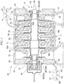
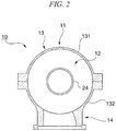
- FIGS. 1 and 2 are diagrams illustrating a sea centrifugal compressor 10 as the rotation mechanism
- FIG. 1 is a cross-sectional view in a radial direction
- FIG. 2 is a diagram taken along the arrow in an A direction in FIG. 1 .
- the sea centrifugal compressor 10 includes a casing 11 as a housing and an internal unit 12 accommodated in the casing 11.
- the casing 11 includes a casing body 13 having a substantially cylindrical shape, a suction port 14 which supplies gas to be compressed into the casing body 13, and a discharge port 15 which discharges the compressed gas from the inside of the casing body 13.
- the casing body 13 is horizontally split into two portions by a horizontal plane, and thus includes an upper half portion 131 and a lower half portion 132.
- fitting concave portions 16 axial movement restricting portions
- the fitting concave portion 16 has a tapered surface 18 formed on each of side walls 17 in the cross-section in the radial direction.
- the tapered surface 18 is formed so that the width thereof in the direction of axis gradually increases from the outer circumferential side to the inner circumferential side along the radial direction.
- the number of fitting concave portions 16, the interval between the adjacent fitting concave portions 16, and the like are not limited to those of this embodiment, and may be appropriately changed depending on the design.
- the internal unit 12 includes a rotor 19 which is provided to be inserted into the casing body 13 in the direction of axis, a bearing portion 20 which supports the rotor 19 to rotate around the axis thereof, a pair of seal portions 21 which seal both end portions of the rotor 19 in the direction of axis, a pair of heads 22 which respectively seal both end openings of the casing body 13, and a plurality of diaphragms 23 which cover the periphery of the rotor 19 with gaps having predetermined widths.
- the internal unit 12 is not limited to the configuration of this embodiment, and the internal unit 12 may be configured to include other components excluding the casing 11 among the components of the sea centrifugal compressor 10.
- the rotor 19 includes a plurality of impellers 192 fixed to circumferential surface of a rotating shaft 191, which is driven to rotate, along the direction of axis.
- a gas flow passage 193 having a predetermined width is formed by the rotor 19, the diaphragms 23, and the heads 22. Both ends of the gas flow passage 193 are respectively connected to the suction port 14 and the discharge port 15.
- five stages of impellers 192 are provided along the direction of axis of the rotating shaft 191, the number of stages of the impellers 192 is not limited thereto, and may be appropriately changed depending on the design.
- the bearing portion 20 rotatably supports the rotating shaft 191 included in the rotor 19 around the axis thereof.
- the bearing portion 20 includes a pair of journal bearings 201 which are provided in both end portions of the rotor 19 in the direction of axis and a thrust bearing 202 which is provided in one end portion of the rotor 19 in the direction of axis.
- the pair of journal bearings 201 receives a load, which is exerted on the rotating shaft 191 in the radial direction.
- the journal bearings 201 are respectively fixed to the outer side surfaces of the pair of heads 22 using fixing means such as bolts.
- the thrust bearing 202 receives a load in the direction of axis, which is exerted on the rotating shaft 191. As illustrated in FIG. 1 , the thrust bearing 202 is mounted on a bearing cover 24 having a box shape, and the bearing cover 24 is fixed to the outer surface of one head 22 using fixing means such as bolts.
- the pair of seal portions 21 have a role of sealing gaps between the rotating shaft 191 included in the rotor 19 and the heads 22.
- the seal portions 21 are so-called dry gas seals, are formed in a ring shape to surround the rotating shaft 191 as illustrated in FIG.1 , and are respectively fixed to the inner surfaces of the pair of heads 22 using fixing means such as bolts.
- the pair of heads 22 are substantially columnar members, and the outside diameters thereof are formed to be approximately equal to those of both end openings of the casing body 13. Both end portions of the rotating shaft 191 included in the rotor 19 are respectively inserted into the heads 22.
- the fitting convex portion 25 (the axial movement restricting portion) having a substantially trapezoidal cross-section is formed to protrude from the outer circumferential surface thereof and extend along the circumferential direction.
- the fitting convex portion 25 is fitted into the fitting concave portion 16 so as to restrict the relative movement between the casing 11 and the internal unit 12.
- a tapered surface 27 is formed on each side wall 26 in the cross-section in the radial direction.
- the tapered surface 27 is formed so that the width thereof in the direction of axis gradually increases from the outer circumferential side to the inner circumferential side in the radial direction.
- the number of fitting convex portions 25, the interval between the adjacent fitting convex portions 25, and the like are not limited to those of this embodiment, and may be appropriately changed depending on the design.
- the diaphragm 23 is a substantially annular member, and is formed to have the fitting convex portion 28 (the axial movement restricting portion) having a substantially trapezoidal cross-section, which protrudes from the outer circumferential surface thereof and extends along the circumferential direction.
- the fitting convex portion 28 of the diaphragm 23 has the same shape and function as the fitting convex portion 25 of the head 22, and thus a description thereof will be omitted here.
- five diaphragms 23 are provided along the direction of axis of the rotating shaft 191. Although not illustrated in the figure in detail, the adjacent diaphragms 23 are fixed together by welding. In addition, in the five diaphragms 23 which are integrated, the diaphragm 23 which is positioned at one end portion thereof is fixed to the inner surface of one head 22 using fixing means such as bolts.
- the fixing of the adjacent diaphragms 23 is not limited to the welding, and another fixing means may also be used.
- the five diaphragms 23 are provided corresponding to the number of stages of the impellers 192.
- the number of diaphragms 23 is not limited thereto, and may be appropriately changed depending on the design.
- the internal unit 12 is integrally configured.
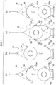
- FIG. 3 is an explanatory view illustrating the maintenance procedure of the sea centrifugal compressor 10 according to this embodiment.
- a worker who performs maintenance removes the fixing means such as bolts used to fix the upper half portion 131 and the lower half portion 132 constituting the casing body 13 so that the upper half portion 131 and the lower half portion 132 are in a splittable state.
- the worker fixes a wire W to the upper half portion 131 and winds up the wire W using a crane (not illustrated) to split the upper half portion 131 from the lower half portion 132 so as to pull up the upper half portion 131. Accordingly, a part of the internal unit 12 is in a state of being exposed.
- the worker fixes the wire W to the exposed part of the internal unit 12, and pulls up the internal unit 12 by winding up the wire W using the crane. Accordingly, the internal unit 12 is taken out from the lower half portion 132.
- the worker allows a spare internal unit 12 to be accommodated in the lower half portion 132 of the casing 11 instead of the taken-out internal unit 12. That is, first, the worker respectively mounts bar-like guide bars 29 onto flanges 132a which protrude from the lower half portion 132 toward both sides thereof respectively so as to extend upward. Subsequently, the worker mounts a pair of guide plates 30 to both side portions of the spare internal unit 12 respectively.
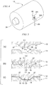
- FIG. 4 is a schematic perspective view schematically illustrating a state where the guide plate 30 is mounted on the internal unit 12.
- the guide plate 30 is a flat plate member having a substantially L-shaped cross-section which has an angle of substantially 90° between a mounting piece 301 and a protruding piece 302.
- the worker allows the mounting piece 301 of the guide plate 30 to abut the spare internal unit 12 on the side portion thereof, and fixes the mounting piece 301 to the internal unit 12 using a bolt.
- the protruding pieces 302 are in a state of respectively protruding from both side portions of the spare internal unit 12 toward both sides thereof.
- the worker fixes the wire W to the internal unit 12 on which the guide plate 30 is mounted and winds up the wire W using the crane to temporarily pull up the spare internal unit 12. Furthermore, the worker lowers the spare internal unit 12 by operating the crane, and inserts the pair of guide bars 29 into the protruding pieces 302 of the pair of guide plates 30 mounted on both side portions of the spare internal unit 12. Thereafter, the worker further lowers the spare internal unit 12 by operating the crane, and then the internal unit 12 is lowered along the pair of guide bars 29.
- the worker When the spare internal unit 12 is lowered to the vicinity of the lower half portion 132, the worker removes the guide plates 30 from both side portions of the internal unit 12, and removes the pair of guide bars 29 from the lower half portion 132. Thereafter, the worker lowers the internal unit 12 to the inside of the lower half portion 132.
- FIG. 5 is a schematic cross-sectional view illustrating the positioning of the spare internal unit 12 and the casing 11 in the direction of axis.
- the proper position of the internal unit 12 means a state where a first center line C1 of the fitting convex portion 28 of the internal unit 12 and a second center line C2 of the fitting concave portion 16 of the lower half portion 132 are not aligned with each other but are split in the direction of axis by a predetermined distance as illustrated in FIG. 5(a) .
- the fitting convex portion 28 is completely fitted into the fitting concave portion 16.
- the internal unit 12 is guided to the proper position by the tapered surface 18 of the fitting concave portion 16 and the tapered surface 27 of the fitting convex portion 28, and thus the fitting convex portion 28 can be reliably fitted into the fitting concave portion 16. Accordingly, even when the internal unit 12 or the lower half portion 132 is subjected to an axial force during the operation of the sea centrifugal compressor 10, relative movement between the internal unit 12 and the lower half portion 132 in the direction of axis is restricted.
- the worker allows the upper half portion 131 and the lower half portion 132 to be integrated. That is, the worker fixes the wire W to the upper half portion 131 which is split as described above, and pulls up the upper half portion 131 by winding up the wire W using the crane to pull up the upper half portion 131.
- the upper half portion 131 is lowered by operating the crane, and joins a pair of flanges 131a which protrude from the upper half portion 131 toward both sides thereof to the flanges 132a which protrude from the lower half portion 132 toward both sides thereof.
- the upper half portion 131 when the upper half portion 131 is lowered, there may be a case where the upper half portion 131 slightly deviates from the proper position in the direction of axis.
- the upper half portion 131 is guided to the proper position by the tapered surface 18 of the fitting concave portion 16 and the tapered surface 27 of the fitting convex portion 28, and thus the fitting convex portion 28 of the internal unit 12 can be reliably fitted into the fitting concave portion 16 of the upper half portion 131. Accordingly, even when the internal unit 12 or the upper half portion 131 is subjected to the axial force during the operation of the sea centrifugal compressor 10, relative movement between the internal unit 12 and the upper half portion 131 in the direction of axis is restricted.
- the worker fixes the upper half portion 131 and the lower half portion 132 to each other using the fixing means such as bolts after removing the wire W from the upper half portion 131. In this way, the maintenance of replacing the internal unit 12 with the spare internal unit 12 is completed.
- FIG. 6 is a schematic cross-sectional view illustrating an axial movement restricting portion 40 according to a first example.
- a fitting concave portion 41 and a fitting convex portion 42 of this example are the same as the fitting concave portion 16 and the fitting convex portion 28 according to the above mentioned embodiment in that tapered surfaces 45 and 46 are respectively formed on side walls 43 and 44 in the cross-section in the radial direction, but are different from them in that the tapered surfaces 45 and 46 are formed only on parts of the side walls 43 and 44.
- the tapered surfaces 45 and 46 are respectively formed only on the opening edge portion of the fitting concave portion 41 and on the base end portion of the fitting convex portion 42. Therefore, in the bottom portion of the fitting concave portion 41, vertical portions 412 perpendicular to a bottom surface 411 are formed. In addition, in the tip end portion of the fitting convex portion 42, vertical portions 422 perpendicular to a top surface 421 are formed.
- FIG. 7 is a schematic cross-sectional view illustrating an axial movement restricting portion 50 according to a second example, which is according to the invention.
- a fitting concave portion 51 and a fitting convex portion 52 of this example are different from the fitting concave portion 41 and the fitting convex portion 42 of the first example in that tapered surfaces are formed only on side walls 53 and 54 on the rearward side in the operational direction of the axial force and are not formed on side walls 57 and 58 on the forward side.
- FIG. 8 is a schematic cross-sectional view illustrating a fitting concave portion 61 of an axial movement restricting portion 60 according to a third modified example.
- the fitting concave portion 61 of this modified example is different from the fitting concave portion 16 and the fitting convex portion 28 according to the first mentioned embodiment in that tapered surfaces 63 are formed only on a part of the fitting concave portion 61 adjacent to a joint portion of the upper half portion 131 and the lower half portion 132 (only the lower half portion 132 is illustrated in FIG. 8 ) of the casing 11 illustrated in FIG. 2 .
- the internal unit 12 in a case where the internal unit 12 slightly deviates from the proper position in the direction of axis when the internal unit 12 is mounted in the casing 11, in the vicinity of the joint portion of the upper half portion 131 and the lower half portion 132 which is the position where the fitting concave portion 61 and a fitting convex portion 62 are initially fitted together, the internal unit 12 is guided to the proper position by the tapered surface 63.
- the internal unit 12 is already at the proper position, and the fitting concave portion 61 and the fitting convex portion 62 are reliably fitted together even though the tapered surface 63 is not formed thereon.
- the centrifugal compressor according to the present invention is not limited thereto, and a centrifugal compressor which is used in a narrow place where a sufficient surrounding space cannot be secured may be applied.
- fitting convex portions 25 and 28 are formed on the heads 22 and the diaphragms 23 in this embodiment, the present invention is not limited thereto, and the fitting convex portions 25 and 28 may be formed on other members included in the internal unit 12.
- fitting concave portion 16 is formed on the casing 11 and the fitting convex portions 25 and 28 are formed on the internal unit 12 in this embodiment, contrary to this, the fitting convex portions 25 and 28 may be formed on the casing 11 and the fitting concave portion 16 may be formed on the internal unit 12.
- FIG. 9 is a schematic plan view illustrating the arrangement example of the sea centrifugal compressor 10 according to the first mentioned embodiment.
- the sea centrifugal compressor 10 is used for a low pressure having a low compression ratio and is disposed in a narrow space between a steam turbine 70 which is used for driving the compressor and a high-pressure compressor 71 having a high compression ratio.
- the steam turbine 70 is disposed on one side of the sea centrifugal compressor 10 and the high-pressure compressor 71 is disposed on other side thereof, the space for taking the internal unit 12 out of the side of the casing 11 cannot be secured.
- the casing 11 is configured to be horizontally split into two portions, and the components other than the casing 11 are integrated with the internal unit 12. Therefore, as described above, by pulling up the internal unit 12 to be replaced with the spare internal unit 12, the maintenance of the sea centrifugal compressor 10 is facilitated. This effect can be obtained even when the tapered surfaces 18 and 27 are not formed on the fitting concave portion 16 of the casing 11 and the fitting convex portion 28 of the internal unit 12.
- the present invention relates to the centrifugal compressor in which the internal unit including the rotor that is driven to rotate around the axis thereof is accommodated in the casing. According to the centrifugal compressor of the present invention, the maintenance can be facilitated by collectively replacing the internal unit, and the internal unit can be taken out without securing the surrounding space.
Landscapes
- Engineering & Computer Science (AREA)
- Mechanical Engineering (AREA)
- General Engineering & Computer Science (AREA)
- Structures Of Non-Positive Displacement Pumps (AREA)
Description
- The present invention relates to a centrifugal compressor in which an internal unit including a rotor configured to be driven to rotate around an axis thereof is accommodated in a casing thereof.
- Priority is claimed on Japanese Patent Application No.
2011-211928, filed on September 28, 2011 - As a rotation mechanism in which a rotor that is driven to rotate around its axis is accommodated in a casing thereof, there is a centrifugal compressor which compresses gas using a centrifugal force. As the centrifugal compressor, a so-called barrel-type compressor having a cylindrical casing and a so-called split-type compressor having a casing that can be split into two portions are known (for example, refer to Published Japanese Translation No.
2009-513863 of the PCT - On the other hand, in the split-type compressor, when the casing on the upper side among the casings which can be split into two portions is detached, the bearing and the seal member are removed along with the casing on the upper side. Accordingly, the rotor and the like inside are exposed, and the maintenance in the inside can be performed at a place where the compressor is installed. In the split-type compressor, since the casings can be split into two portions, compared to the barrel-type compressor, the internal airtightness is poor, and thus the split-type compressor is likely to be applied to centrifugal compressors having a low internal pressure.
- However, as a sea compressor used in the facilities which refine petroleum or natural gas on a ship, the barrel-type compressor is mainly used. This is because it is difficult to perform maintenance in the inside of the compressor on the sea where only a limited space and a minimum number of personnel can be ensured. Therefore, the barrel-type compressor which can be easily maintained by collectively replacing the components in the inside thereof is appropriate.
- The prior art is represented by any of the documents
JP-S60-180800U GB-A-1381904 JP-S63-170591A - However, in the conventional barrel-type compressor which is mainly used as the sea compressor, since the internal unit needs to be pulled out from one end opening of the casing as described above, there are problems in that a sufficient space needs to be secured adjacent to the compressor and it is difficult to perform an operation of pulling out the internal unit from the casing in a transverse direction.
- This object is solved by a centrifugal compressor with the features if claim 1. A preferred embodiment follows from claim 2. The present invention provides a centrifugal compressor which can be easily maintained by collectively replacing an internal unit thereof and in which the internal unit can be taken out without securing a surrounding space.
- According to a first aspect of the present invention, a centrifugal compressor according to claim 1 is provided.
- According to this configuration, the upper half portion of the casing is removed, the internal unit is taken out from the lower half portion of the casing by pulling it up, and thereafter a new internal unit is pulled down to be mounted on the half portion of the casing. Therefore, the components in the centrifugal compressor can be collectively replaced. Accordingly, even in a case where a sufficient surrounding space cannot be secured on the sea, for example, the maintenance of the internal unit can be easily performed.
- In addition, by fitting the fitting concave portion formed on one of the internal unit and the casing and the fitting convex portion formed on the other thereof together, relative movement between the internal unit and the casing in the direction of axis can be restricted.
- Furthermore, when the internal unit is mounted on the casing, there may be a case where the internal unit slightly deviates from a position where the fitting concave portion and the fitting convex portion are properly fitted together in the direction of axis. Even in this case, the internal unit is guided to the proper position by the tapered surfaces formed on the fitting concave portion and the fitting convex portion, and thus the fitting concave portion and the fitting convex portion are reliably fitted together.
- In addition, according to the invention, in each of cross-sections of the fitting concave portion and the fitting convex portion in the radial direction, the tapered surface is formed only on a side wall on a rearward side in an operational direction of an axial force applied to the internal unit.
- According to this configuration, the tapered surface is formed only on the side wall on the rearward side in the operational direction of the axial force, and is not formed on the side wall on the forward side. Therefore, there is no loss of function of the axial movement restricting portion regardless of the presence of the tapered surface, and relative movement between the casing and the internal unit in the direction of axis due to the action of the axial force can be reliably restricted by the side wall on the forward side.
- In addition, according to a second aspect of the present invention, the tapered surface may be formed only on a part of the fitting concave portion and the fitting convex portion adjacent to a joint portion of the upper half portion and the lower half portion of the casing.
- According to this configuration, in a case where the internal unit slightly deviates from the proper position in the direction of axis when the internal unit is mounted on the casing, in the vicinity of the joint portion of the upper half portion and the lower half portion which is the position where the fitting concave portion and the fitting convex portion are initially fitted together, the internal unit is guided to the proper position by the tapered surface. Therefore, when the fitting concave portion and the fitting convex portion start to be fitted together at a position distant from the vicinity of the joint portion, the internal unit is already at the proper position, and the fitting concave portion and the fitting convex portion are reliably fitted together even though the tapered surface is not formed thereon.
- In addition, according to the first aspect of the present invention, an internal unit of a centrifugal compressor, which is disposed in a casing that is configured to be horizontally split into two portions and includes an upper half portion on the upper side and a lower half portion on the lower side, and has a configuration in which a rotor which rotates around an axis thereof, a bearing portion which rotatably supports the rotor, and an annular seal portion which seals a gap surrounding a circumferential surface of the rotor so as to enable the rotor to rotate are integrated, includes an axial movement restricting portion which includes a fitting concave portion provided on one of the casing and the internal unit and a fitting convex portion provided on the other thereof to be fitted into the fitting concave portion as a pair and restricts relative movement between the casing and the internal unit in a direction of axis; and a tapered surface which is formed on each of the fitting concave portion and the fitting convex portion so that the width thereof in the direction of axis increases toward an inner circumferential side in a radial direction.
- According to this configuration, the upper half portion of the casing is removed, the internal unit is pulled up to be taken out from the lower half portion of the casing, and thereafter a new internal unit is pulled down to be mounted on the lower half portion of the casing. Therefore, the components in the centrifugal compressor can be collectively replaced. Accordingly, even in a case where a sufficient surrounding space cannot be secured on the sea, for example, the maintenance of the internal unit can be easily performed.
- In addition, by fitting the fitting concave portion formed on one of the internal unit and the casing and the fitting convex portion formed on the other thereof together, relative movement between the internal unit and the casing in the direction of axis can be restricted.
- Furthermore, when the internal unit is mounted on the casing, there may be a case where the internal unit slightly deviates from a position where the fitting concave portion and the fitting convex portion are properly fitted together in the direction of axis. Even in this case, the internal unit is guided to the proper position by the tapered surfaces formed on the fitting concave portion and the fitting convex portion, and thus the fitting concave portion and the fitting convex portion are reliably fitted together.
- In the centrifugal compressor according to the present invention, the maintenance can be facilitated by collectively replacing the internal unit, and the internal unit can be taken out without securing the surrounding space.
-
-
FIG. 1 is a cross-sectional view in a radial direction illustrating the configuration of a sea centrifugal not forming part of the invention. -
FIG. 2 is a diagram taken along the arrow in an A direction inFIG. 1 . -
FIG. 3 is an explanatory view illustrating a maintenance procedure of a sea centrifugal compressor. -
FIG. 4 is a schematic perspective view schematically illustrating a state where a guide plate is mounted on an internal unit. -
FIG. 5 is a schematic cross-sectional view illustrating the positioning of an internal unit and a casing in a direction of axis not forming part of the invention. -
FIG. 6 is a schematic cross-sectional view illustrating an axial movement restricting portion according to a first example not forming part of the invention. -
FIG. 7 is a schematic cross-sectional view illustrating an axial movement restricting portion according to a second example according to the invention. -
FIG. 8 is a schematic cross-sectional view illustrating an axial movement restricting portion according to a third modified example not forming part of the invention. -
FIG. 9 is a schematic plan view illustrating an arrangement example of a sea centrifugal compressor. - Hereinafter, examples as well as an exemplary embodiment of the present invention will be described with reference to the drawings. It should be noted here that in the following development, the terms "embodiment" and "example" should be regarded as related to non-claimed supportive examples, unless explicitly specified as being part of the invention.
- First, the configuration of a rotation mechanism will be described.
FIGS. 1 and2 are diagrams illustrating a seacentrifugal compressor 10 as the rotation mechanism,FIG. 1 is a cross-sectional view in a radial direction, andFIG. 2 is a diagram taken along the arrow in an A direction inFIG. 1 . - As illustrated in
FIG. 1 , the seacentrifugal compressor 10 includes acasing 11 as a housing and aninternal unit 12 accommodated in thecasing 11. - As illustrated in
FIGS. 1 and2 , thecasing 11 includes acasing body 13 having a substantially cylindrical shape, asuction port 14 which supplies gas to be compressed into thecasing body 13, and adischarge port 15 which discharges the compressed gas from the inside of thecasing body 13. - As illustrated in
FIG.2 , thecasing body 13 is horizontally split into two portions by a horizontal plane, and thus includes anupper half portion 131 and alower half portion 132. As illustrated inFIG. 1 , in the inner circumferential surfaces of theupper half portion 131 and thelower half portion 132, fitting concave portions 16 (axial movement restricting portions) having a substantially trapezoidal cross-section are formed to extend along a circumferential direction. The fittingconcave portions 16 and fitting convexportions casing 11 and theinternal unit 12, and a plurality of lines of the fittingconcave portions 16 are formed at predetermined intervals in the direction of axis. - Here, as illustrated by the enlarged part in
FIG. 1 , the fittingconcave portion 16 has atapered surface 18 formed on each ofside walls 17 in the cross-section in the radial direction. The taperedsurface 18 is formed so that the width thereof in the direction of axis gradually increases from the outer circumferential side to the inner circumferential side along the radial direction. The number of fittingconcave portions 16, the interval between the adjacent fittingconcave portions 16, and the like are not limited to those of this embodiment, and may be appropriately changed depending on the design. - As illustrated in
FIG. 1 , theinternal unit 12 includes arotor 19 which is provided to be inserted into thecasing body 13 in the direction of axis, a bearingportion 20 which supports therotor 19 to rotate around the axis thereof, a pair ofseal portions 21 which seal both end portions of therotor 19 in the direction of axis, a pair ofheads 22 which respectively seal both end openings of thecasing body 13, and a plurality ofdiaphragms 23 which cover the periphery of therotor 19 with gaps having predetermined widths. Theinternal unit 12 is not limited to the configuration of this embodiment, and theinternal unit 12 may be configured to include other components excluding thecasing 11 among the components of the seacentrifugal compressor 10. - The
rotor 19 includes a plurality ofimpellers 192 fixed to circumferential surface of arotating shaft 191, which is driven to rotate, along the direction of axis. Agas flow passage 193 having a predetermined width is formed by therotor 19, thediaphragms 23, and theheads 22. Both ends of thegas flow passage 193 are respectively connected to thesuction port 14 and thedischarge port 15. In this embodiment, although five stages ofimpellers 192 are provided along the direction of axis of therotating shaft 191, the number of stages of theimpellers 192 is not limited thereto, and may be appropriately changed depending on the design. - The bearing
portion 20 rotatably supports therotating shaft 191 included in therotor 19 around the axis thereof. As illustrated inFIG. 1 , the bearingportion 20 includes a pair ofjournal bearings 201 which are provided in both end portions of therotor 19 in the direction of axis and athrust bearing 202 which is provided in one end portion of therotor 19 in the direction of axis. - The pair of
journal bearings 201 receives a load, which is exerted on therotating shaft 191 in the radial direction. Thejournal bearings 201 are respectively fixed to the outer side surfaces of the pair ofheads 22 using fixing means such as bolts. - The
thrust bearing 202 receives a load in the direction of axis, which is exerted on therotating shaft 191. As illustrated inFIG. 1 , thethrust bearing 202 is mounted on abearing cover 24 having a box shape, and thebearing cover 24 is fixed to the outer surface of onehead 22 using fixing means such as bolts. - The pair of
seal portions 21 have a role of sealing gaps between therotating shaft 191 included in therotor 19 and theheads 22. Theseal portions 21 are so-called dry gas seals, are formed in a ring shape to surround therotating shaft 191 as illustrated inFIG.1 , and are respectively fixed to the inner surfaces of the pair ofheads 22 using fixing means such as bolts. - As illustrated in
FIG. 1 , the pair ofheads 22 are substantially columnar members, and the outside diameters thereof are formed to be approximately equal to those of both end openings of thecasing body 13. Both end portions of therotating shaft 191 included in therotor 19 are respectively inserted into theheads 22. In addition, in eachhead 22, the fitting convex portion 25 (the axial movement restricting portion) having a substantially trapezoidal cross-section is formed to protrude from the outer circumferential surface thereof and extend along the circumferential direction. The fittingconvex portion 25 is fitted into the fittingconcave portion 16 so as to restrict the relative movement between thecasing 11 and theinternal unit 12. - Here, as illustrated by the enlarged part in
FIG. 1 , in the fittingconvex portion 25, atapered surface 27 is formed on eachside wall 26 in the cross-section in the radial direction. As in the taperedsurface 18 of the fittingconcave portion 16, the taperedsurface 27 is formed so that the width thereof in the direction of axis gradually increases from the outer circumferential side to the inner circumferential side in the radial direction. The number of fittingconvex portions 25, the interval between the adjacent fittingconvex portions 25, and the like are not limited to those of this embodiment, and may be appropriately changed depending on the design. - As illustrated in
FIG.1 , thediaphragm 23 is a substantially annular member, and is formed to have the fitting convex portion 28 (the axial movement restricting portion) having a substantially trapezoidal cross-section, which protrudes from the outer circumferential surface thereof and extends along the circumferential direction. The fittingconvex portion 28 of thediaphragm 23 has the same shape and function as the fittingconvex portion 25 of thehead 22, and thus a description thereof will be omitted here. - As illustrated in
FIG. 1 , fivediaphragms 23 are provided along the direction of axis of therotating shaft 191. Although not illustrated in the figure in detail, theadjacent diaphragms 23 are fixed together by welding. In addition, in the fivediaphragms 23 which are integrated, thediaphragm 23 which is positioned at one end portion thereof is fixed to the inner surface of onehead 22 using fixing means such as bolts. - The fixing of the
adjacent diaphragms 23 is not limited to the welding, and another fixing means may also be used. In addition, in this embodiment, the fivediaphragms 23 are provided corresponding to the number of stages of theimpellers 192. However, the number ofdiaphragms 23 is not limited thereto, and may be appropriately changed depending on the design. - As described above, since the
rotor 19, the bearingportion 20, theseal portions 21, the pair ofheads 22, and the fivediaphragms 23 which constitute theinternal unit 12 are fixed to each other, theinternal unit 12 is integrally configured. - Next, a maintenance procedure of the sea
centrifugal compressor 10 according to this embodiment and an operational effect thereof will be described.FIG. 3 is an explanatory view illustrating the maintenance procedure of the seacentrifugal compressor 10 according to this embodiment. First, in a state illustrated inFIG. 2 , a worker who performs maintenance removes the fixing means such as bolts used to fix theupper half portion 131 and thelower half portion 132 constituting thecasing body 13 so that theupper half portion 131 and thelower half portion 132 are in a splittable state. - Subsequently, as illustrated in
FIG. 3(a) , the worker fixes a wire W to theupper half portion 131 and winds up the wire W using a crane (not illustrated) to split theupper half portion 131 from thelower half portion 132 so as to pull up theupper half portion 131. Accordingly, a part of theinternal unit 12 is in a state of being exposed. - Subsequently, as illustrated in
FIG. 3(b) , the worker fixes the wire W to the exposed part of theinternal unit 12, and pulls up theinternal unit 12 by winding up the wire W using the crane. Accordingly, theinternal unit 12 is taken out from thelower half portion 132. - Subsequently, as illustrated in
FIG. 3(c) , the worker allows a spareinternal unit 12 to be accommodated in thelower half portion 132 of thecasing 11 instead of the taken-outinternal unit 12. That is, first, the worker respectively mounts bar-like guide bars 29 ontoflanges 132a which protrude from thelower half portion 132 toward both sides thereof respectively so as to extend upward. Subsequently, the worker mounts a pair ofguide plates 30 to both side portions of the spareinternal unit 12 respectively. -
FIG. 4 is a schematic perspective view schematically illustrating a state where theguide plate 30 is mounted on theinternal unit 12. Theguide plate 30 is a flat plate member having a substantially L-shaped cross-section which has an angle of substantially 90° between a mountingpiece 301 and aprotruding piece 302. The worker allows the mountingpiece 301 of theguide plate 30 to abut the spareinternal unit 12 on the side portion thereof, and fixes the mountingpiece 301 to theinternal unit 12 using a bolt. Accordingly, as illustrated inFIGS. 3(c) and4 , the protrudingpieces 302 are in a state of respectively protruding from both side portions of the spareinternal unit 12 toward both sides thereof. - The worker fixes the wire W to the
internal unit 12 on which theguide plate 30 is mounted and winds up the wire W using the crane to temporarily pull up the spareinternal unit 12. Furthermore, the worker lowers the spareinternal unit 12 by operating the crane, and inserts the pair of guide bars 29 into the protrudingpieces 302 of the pair ofguide plates 30 mounted on both side portions of the spareinternal unit 12. Thereafter, the worker further lowers the spareinternal unit 12 by operating the crane, and then theinternal unit 12 is lowered along the pair of guide bars 29. - When the spare
internal unit 12 is lowered to the vicinity of thelower half portion 132, the worker removes theguide plates 30 from both side portions of theinternal unit 12, and removes the pair of guide bars 29 from thelower half portion 132. Thereafter, the worker lowers theinternal unit 12 to the inside of thelower half portion 132. - Here,
FIG. 5 is a schematic cross-sectional view illustrating the positioning of the spareinternal unit 12 and thecasing 11 in the direction of axis. When theinternal unit 12 is lowered to the inside of thelower half portion 132, there may be a case where theinternal unit 12 slightly deviates from a proper position in the direction of axis. Here, the proper position of theinternal unit 12 means a state where a first center line C1 of the fittingconvex portion 28 of theinternal unit 12 and a second center line C2 of the fittingconcave portion 16 of thelower half portion 132 are not aligned with each other but are split in the direction of axis by a predetermined distance as illustrated inFIG. 5(a) . - In this case, when the
internal unit 12 is further lowered from the state ofFIG. 5(a) , as illustrated inFIG. 5(b) , the taperedsurface 27 of the fittingconvex portion 28 comes into contact with the taperedsurface 18 of the fittingconcave portion 16. When theinternal unit 12 is further lowered from this state, the fittingconvex portion 28 is caused to slide obliquely downward along the taperedsurface 18 of the fittingconcave portion 16. Accordingly, the first center line C1 of the fittingconvex portion 28 gradually approaches the second center line C2 of the fittingconcave portion 16. - When the
internal unit 12 is further lowered from the state ofFIG. 5(b) , as illustrated inFIG.5(c) , the first center line C1 of the fittingconvex portion 28 is aligned with the second center line C2 of the fittingconcave portion 16. - At this time, the fitting
convex portion 28 is completely fitted into the fittingconcave portion 16. As described above, even in a case where theinternal unit 12 deviates from the proper position in the direction of axis, theinternal unit 12 is guided to the proper position by the taperedsurface 18 of the fittingconcave portion 16 and the taperedsurface 27 of the fittingconvex portion 28, and thus the fittingconvex portion 28 can be reliably fitted into the fittingconcave portion 16. Accordingly, even when theinternal unit 12 or thelower half portion 132 is subjected to an axial force during the operation of the seacentrifugal compressor 10, relative movement between theinternal unit 12 and thelower half portion 132 in the direction of axis is restricted. - Finally, as illustrated in
FIG. 3(d) , the worker allows theupper half portion 131 and thelower half portion 132 to be integrated. That is, the worker fixes the wire W to theupper half portion 131 which is split as described above, and pulls up theupper half portion 131 by winding up the wire W using the crane to pull up theupper half portion 131. Theupper half portion 131 is lowered by operating the crane, and joins a pair offlanges 131a which protrude from theupper half portion 131 toward both sides thereof to theflanges 132a which protrude from thelower half portion 132 toward both sides thereof. - At this time, when the
upper half portion 131 is lowered, there may be a case where theupper half portion 131 slightly deviates from the proper position in the direction of axis. However, in this case, as in the case of lowering theinternal unit 12, theupper half portion 131 is guided to the proper position by the taperedsurface 18 of the fittingconcave portion 16 and the taperedsurface 27 of the fittingconvex portion 28, and thus the fittingconvex portion 28 of theinternal unit 12 can be reliably fitted into the fittingconcave portion 16 of theupper half portion 131. Accordingly, even when theinternal unit 12 or theupper half portion 131 is subjected to the axial force during the operation of the seacentrifugal compressor 10, relative movement between theinternal unit 12 and theupper half portion 131 in the direction of axis is restricted. - Although not illustrated in the figure in detail, the worker fixes the
upper half portion 131 and thelower half portion 132 to each other using the fixing means such as bolts after removing the wire W from theupper half portion 131. In this way, the maintenance of replacing theinternal unit 12 with the spareinternal unit 12 is completed. - The cross-sectional shapes of the fitting
concave portion 16 and the fittingconvex portion 28 are not limited to the substantially trapezoidal cross-sectional shape of this embodiment, and may be appropriately changed depending on the design.FIG. 6 is a schematic cross-sectional view illustrating an axialmovement restricting portion 40 according to a first example. A fittingconcave portion 41 and a fittingconvex portion 42 of this example are the same as the fittingconcave portion 16 and the fittingconvex portion 28 according to the above mentioned embodiment in that tapered surfaces 45 and 46 are respectively formed onside walls tapered surfaces side walls concave portion 41 and the fittingconvex portion 42 of this modified example, thetapered surfaces concave portion 41 and on the base end portion of the fittingconvex portion 42. Therefore, in the bottom portion of the fittingconcave portion 41,vertical portions 412 perpendicular to abottom surface 411 are formed. In addition, in the tip end portion of the fittingconvex portion 42,vertical portions 422 perpendicular to atop surface 421 are formed. According to this configuration, loss of function of the fittingconcave portion 41 and the fittingconvex portion 42 is suppressed and minimized by the presence of the tapered surfaces 45 and 46, and the relative movement between thecasing 11 and theinternal unit 12 in the direction of axis due to the action of the axial force can be reliably restricted by the joining of the vertical portion and the vertical portion. -
FIG. 7 is a schematic cross-sectional view illustrating an axialmovement restricting portion 50 according to a second example, which is according to the invention. A fittingconcave portion 51 and a fittingconvex portion 52 of this example are different from the fittingconcave portion 41 and the fittingconvex portion 42 of the first example in that tapered surfaces are formed only onside walls side walls concave portion 51 and the fittingconvex portion 52 regardless of the presence of the tapered surfaces, and the relative movement between thecasing 11 and theinternal unit 12 in the direction of axis due to the action of the axial force can be reliably restricted by the joining of theside walls -
FIG. 8 is a schematic cross-sectional view illustrating a fittingconcave portion 61 of an axialmovement restricting portion 60 according to a third modified example. The fittingconcave portion 61 of this modified example is different from the fittingconcave portion 16 and the fittingconvex portion 28 according to the first mentioned embodiment in that tapered surfaces 63 are formed only on a part of the fittingconcave portion 61 adjacent to a joint portion of theupper half portion 131 and the lower half portion 132 (only thelower half portion 132 is illustrated inFIG. 8 ) of thecasing 11 illustrated inFIG. 2 . According to this configuration, in a case where theinternal unit 12 slightly deviates from the proper position in the direction of axis when theinternal unit 12 is mounted in thecasing 11, in the vicinity of the joint portion of theupper half portion 131 and thelower half portion 132 which is the position where the fittingconcave portion 61 and a fitting convex portion 62 are initially fitted together, theinternal unit 12 is guided to the proper position by the taperedsurface 63. Therefore, when the fittingconcave portion 61 and the fitting convex portion 62 start to be fitted together at a position distant from the vicinity of the joint portion, theinternal unit 12 is already at the proper position, and the fittingconcave portion 61 and the fitting convex portion 62 are reliably fitted together even though the taperedsurface 63 is not formed thereon. - Although the sea
centrifugal compressor 10 is described in this development, the centrifugal compressor according to the present invention is not limited thereto, and a centrifugal compressor which is used in a narrow place where a sufficient surrounding space cannot be secured may be applied. - In addition, although the fitting
convex portions heads 22 and thediaphragms 23 in this embodiment, the present invention is not limited thereto, and the fittingconvex portions internal unit 12. - In addition, although the fitting
concave portion 16 is formed on thecasing 11 and the fittingconvex portions internal unit 12 in this embodiment, contrary to this, the fittingconvex portions casing 11 and the fittingconcave portion 16 may be formed on theinternal unit 12. - Next, an arrangement example of a sea
centrifugal compressor 10 will be described.FIG. 9 is a schematic plan view illustrating the arrangement example of the seacentrifugal compressor 10 according to the first mentioned embodiment. The seacentrifugal compressor 10 is used for a low pressure having a low compression ratio and is disposed in a narrow space between asteam turbine 70 which is used for driving the compressor and a high-pressure compressor 71 having a high compression ratio. According to this arrangement, since thesteam turbine 70 is disposed on one side of the seacentrifugal compressor 10 and the high-pressure compressor 71 is disposed on other side thereof, the space for taking theinternal unit 12 out of the side of thecasing 11 cannot be secured. However, in the seacentrifugal compressor 10, thecasing 11 is configured to be horizontally split into two portions, and the components other than thecasing 11 are integrated with theinternal unit 12. Therefore, as described above, by pulling up theinternal unit 12 to be replaced with the spareinternal unit 12, the maintenance of the seacentrifugal compressor 10 is facilitated. This effect can be obtained even when thetapered surfaces concave portion 16 of thecasing 11 and the fittingconvex portion 28 of theinternal unit 12. - While an example of the present invention has been described above, the present invention is not limited to the above-described example, but is defined by the appended claims. Additions, omissions, substitutions, and other modifications of the configuration can be made within the scope of the appended claims. The present invention is not limited to the above descriptions, and is limited only by the appended claims.
- The present invention relates to the centrifugal compressor in which the internal unit including the rotor that is driven to rotate around the axis thereof is accommodated in the casing. According to the centrifugal compressor of the present invention, the maintenance can be facilitated by collectively replacing the internal unit, and the internal unit can be taken out without securing the surrounding space.
-
- 10:
- sea centrifugal compressor
- 11:
- casing
- 12:
- internal unit
- 13:
- casing body
- 131:
- upper half portion
- 131a:
- flange
- 132:
- lower half portion
- 132a:
- flange
- 14:
- suction port
- 15:
- discharge port
- 16:
- fitting concave portion
- 17:
- side wall
- 18:
- tapered surface
- 19:
- rotor
- 191:
- rotating shaft
- 192:
- impeller
- 193:
- gas flow passage
- 20:
- bearing portion
- 201:
- journal bearing
- 202:
- thrust bearing
- 21:
- seal portion
- 22:
- head
- 23:
- diaphragm
- 24:
- bearing cover
- 25:
- fitting convex portion
- 26:
- side wall
- 27:
- tapered surface
- 28:
- fitting convex portion
- 29:
- guide bar
- 30:
- guide plate
- 301:
- mounting piece
- 302:
- protruding piece
- 40:
- axial movement restricting portion
- 41:
- fitting concave portion
- 411:
- bottom surface
- 412:
- vertical portion
- 42:
- fitting convex portion
- 421:
- top surface
- 422:
- vertical portion
- 43:
- side wall
- 44:
- side wall
- 45:
- tapered surface
- 46:
- tapered surface
- 50:
- axial movement restricting portion
- 51:
- fitting concave portion
- 52:
- fitting convex portion
- 53:
- side wall
- 54:
- side wall
- 57:
- side wall
- 58:
- side wall
- 60:
- axial movement restricting portion
- 61:
- fitting concave portion
- 62:
- fitting convex portion
- 63:
- tapered surface
- 70:
- steam turbine
- 71:
- high-pressure compressor
- C1:
- first center line
- C2:
- second center line
- W:
- wire
Claims (2)
- A centrifugal compressor, comprising:a casing (11) which is configured to be horizontally split into two portions and includes an upper half portion (131) on an upper side and a lower half portion (132) on a lower side;an internal unit (12) which is disposed in the casing (11) and in which a rotor (19) configured to rotate around an axis thereof, a bearing portion (20) which rotatably supports the rotor (19), and an annular seal portion (21) which seals a gap surrounding a circumferential surface of the rotor (19) so as to enable the rotor (19) to rotate are integrated;an axial movement restricting portion which includes a fitting concave portion (16) provided in one of the casing (11) and the internal unit (12) and a fitting convex portion (28) provided in the other thereof to be fitted into the fitting concave portion (16) as a pair and restricts relative movement between the casing (11) and the internal unit (12) in a direction of the axis; anda tapered surface which is formed on each of the fitting concave portion (16) and the fitting convex portion (28) so that a width thereof in the direction of the axis increases toward an inner circumferential side in a radial direction,characterized in that in cross-sections in the radial direction of both the fitting concave portion (16) and the fitting convex portion (28), the tapered surface is formed only on a side wall on a rearward side in a direction of an operational axial force applied to the internal unit (12) and are not formed on side walls (57, 58) on the forward side, andwherein in cross-sections in the radial direction of both the fitting concave portion (16) and the fitting convex portion (28), a side wall on a forward side in a direction of an operational axial force applied to the internal unit (12) is formed perpendicular to the direction of the axis.
- The centrifugal compressor according to claim 1,
wherein the tapered surface (63) is formed only on a part of each fitting concave portion (61) and fitting convex portion (62) adjacent to a joint portion of the upper half portion (131) and the lower half portion (132) of the casing (11).
Applications Claiming Priority (2)
| Application Number | Priority Date | Filing Date | Title |
|---|---|---|---|
| JP2011211928A JP5868646B2 (en) | 2011-09-28 | 2011-09-28 | Rotating machine |
| PCT/JP2012/074538 WO2013047507A1 (en) | 2011-09-28 | 2012-09-25 | Rotation mechanism and internal unit of rotation mechanism |
Publications (3)
| Publication Number | Publication Date |
|---|---|
| EP2762729A1 EP2762729A1 (en) | 2014-08-06 |
| EP2762729A4 EP2762729A4 (en) | 2015-06-03 |
| EP2762729B1 true EP2762729B1 (en) | 2018-12-12 |
Family
ID=47995539
Family Applications (1)
| Application Number | Title | Priority Date | Filing Date |
|---|---|---|---|
| EP12836322.3A Not-in-force EP2762729B1 (en) | 2011-09-28 | 2012-09-25 | Centrifugal compressor |
Country Status (5)
| Country | Link |
|---|---|
| US (1) | US10077783B2 (en) |
| EP (1) | EP2762729B1 (en) |
| JP (1) | JP5868646B2 (en) |
| CN (1) | CN103717907B (en) |
| WO (1) | WO2013047507A1 (en) |
Families Citing this family (21)
| Publication number | Priority date | Publication date | Assignee | Title |
|---|---|---|---|---|
| EP2706199B1 (en) * | 2012-09-10 | 2018-12-12 | Ansaldo Energia Switzerland AG | Method and guide for removing an inner casing from a turbomachine |
| CN103603828A (en) * | 2013-12-01 | 2014-02-26 | 湖北双剑鼓风机股份有限公司 | Draught fan partition plate |
| DE102014207461A1 (en) * | 2014-04-17 | 2015-10-22 | Siemens Aktiengesellschaft | Arrangement of components of a fluid energy machine, joining method |
| US9726194B2 (en) | 2014-04-21 | 2017-08-08 | Solar Turbines Incorporated | Universal housing for a centrifugal gas compressor |
| KR101615209B1 (en) * | 2014-07-31 | 2016-04-25 | 두산중공업 주식회사 | Turbine having packing device and assembling method of the same and sealing assembly |
| JP2016040461A (en) * | 2014-08-13 | 2016-03-24 | 三菱重工業株式会社 | Centrifugal rotary machine |
| EP3165776B1 (en) * | 2015-11-03 | 2020-04-22 | Howden Turbo GmbH | Turbo compressor with stiffening ribs |
| EP3171033A1 (en) * | 2015-11-19 | 2017-05-24 | Grundfos Holding A/S | Multistage centrifugal pump with casing opening for the maintenance of an axial thrust balancing piston |
| US10689187B2 (en) * | 2016-11-28 | 2020-06-23 | Mitsubishi Heavy Industries Compressor Corporation | Rotor securing jig and rotor storage unit |
| JP7070972B2 (en) * | 2016-12-08 | 2022-05-18 | アトラス コプコ コンプテック, エルエルシー | Waste heat recovery system |
| CN107956745B (en) * | 2017-10-31 | 2019-04-26 | 沈阳透平机械股份有限公司 | Drum Type Refrigerant Compressor |
| EP3770441B1 (en) * | 2018-04-27 | 2026-05-06 | Mitsubishi Heavy Industries Compressor Corporation | Compressor and method for manufacturing compressor |
| CN110748493A (en) * | 2018-07-23 | 2020-02-04 | 沈阳斯特机械制造有限公司 | Centrifugal compressor for diesel oil hydrogenation modification device |
| JP7108555B2 (en) | 2019-02-01 | 2022-07-28 | 三菱重工コンプレッサ株式会社 | compressor |
| CN110656987B (en) * | 2019-09-18 | 2025-02-14 | 中国电建集团山东电力建设第一工程有限公司 | Sealed casing and steam turbine |
| WO2021079858A1 (en) * | 2019-10-25 | 2021-04-29 | 日立Astemo株式会社 | Rotating electric machine and method for manufacturing rotating electric machine |
| JP7333247B2 (en) * | 2019-11-01 | 2023-08-24 | 三菱重工コンプレッサ株式会社 | Ammonia plant synthesis gas compressor train |
| US11536291B2 (en) * | 2020-02-04 | 2022-12-27 | Mitsubishi Heavy Industries Compressor Corporation | Rotor hanging tool, rotor support jig, rotor lifting method, and rotary machine disassembly method |
| JP7565690B2 (en) * | 2020-02-07 | 2024-10-11 | 三菱重工コンプレッサ株式会社 | Compressor manufacturing method and compressor |
| JP7390963B2 (en) | 2020-04-20 | 2023-12-04 | 三菱重工コンプレッサ株式会社 | Hanging tools, support jigs, disassembly methods for rotating machines, and methods for assembling rotating machines |
| US11703278B2 (en) * | 2020-06-19 | 2023-07-18 | Mitsubishi Heavy Industries Compressor Corporation | Liquefied natural gas compression system |
Family Cites Families (16)
| Publication number | Priority date | Publication date | Assignee | Title |
|---|---|---|---|---|
| US2578617A (en) * | 1946-11-15 | 1951-12-11 | Worthington Pump & Mach Corp | Multistage centrifugal compressor |
| US2556384A (en) * | 1949-02-15 | 1951-06-12 | Frederick H Zeitz | Self-aligning well pump base |
| US2781999A (en) * | 1954-09-24 | 1957-02-19 | Siemens Ag | Turbine construction |
| GB1381904A (en) | 1971-07-13 | 1975-01-29 | Carrier Corp | Multi-stage two section centrifugal compressor |
| JPS5813781B2 (en) | 1978-10-19 | 1983-03-15 | 三井造船株式会社 | Pressure equalization structure of shaft sealing device |
| JPS5692802U (en) * | 1979-12-18 | 1981-07-23 | ||
| JPS5828844B2 (en) | 1979-12-27 | 1983-06-18 | 三菱化学株式会社 | Method for stabilizing carbamates |
| JPS5954800A (en) | 1982-09-22 | 1984-03-29 | Hitachi Ltd | Horizontally separated casing |
| JPS6081984U (en) | 1983-11-07 | 1985-06-06 | 三菱重工業株式会社 | Turbine rotor lifting jig |
| US4600224A (en) * | 1983-12-23 | 1986-07-15 | Interlock Technologies Corporation | Tubular connection having a chevron wedge thread |
| JPS60180800U (en) * | 1984-05-10 | 1985-11-30 | 三菱重工業株式会社 | Double suction multistage volute pump |
| JP2533508B2 (en) * | 1987-01-07 | 1996-09-11 | 株式会社日立製作所 | Composite horizontal split casing for fluid machinery |
| JPH04323192A (en) | 1991-04-22 | 1992-11-12 | Hitachi Plant Eng & Constr Co Ltd | Lifting device of turbine rotor |
| JP3726005B2 (en) * | 2000-03-09 | 2005-12-14 | 株式会社 日立インダストリイズ | Multistage centrifugal compressor |
| DE102005052077B4 (en) | 2005-10-28 | 2016-11-24 | Man Diesel & Turbo Se | Device for the lateral mounting and dismounting of a compressor barrel |
| JP4844573B2 (en) * | 2008-02-01 | 2011-12-28 | 株式会社デンソー | Fuel supply pump |
-
2011
- 2011-09-28 JP JP2011211928A patent/JP5868646B2/en not_active Expired - Fee Related
-
2012
- 2012-09-25 CN CN201280038541.2A patent/CN103717907B/en not_active Expired - Fee Related
- 2012-09-25 WO PCT/JP2012/074538 patent/WO2013047507A1/en not_active Ceased
- 2012-09-25 EP EP12836322.3A patent/EP2762729B1/en not_active Not-in-force
- 2012-09-25 US US14/237,968 patent/US10077783B2/en active Active
Non-Patent Citations (1)
| Title |
|---|
| None * |
Also Published As
| Publication number | Publication date |
|---|---|
| JP5868646B2 (en) | 2016-02-24 |
| EP2762729A1 (en) | 2014-08-06 |
| JP2013072356A (en) | 2013-04-22 |
| US10077783B2 (en) | 2018-09-18 |
| CN103717907A (en) | 2014-04-09 |
| US20140178183A1 (en) | 2014-06-26 |
| EP2762729A4 (en) | 2015-06-03 |
| CN103717907B (en) | 2017-02-15 |
| WO2013047507A1 (en) | 2013-04-04 |
Similar Documents
| Publication | Publication Date | Title |
|---|---|---|
| US10077783B2 (en) | Rotation mechanism and internal unit of rotation mechanism | |
| CN105683584B (en) | The method for dismounting of the dismounting packing ring assemblies of stator blade segment and the stator blade segment using the component | |
| CN103306994B (en) | Centrifugal compressed device and assembling method thereof | |
| EP2679824B1 (en) | Compressor | |
| CN103228930B (en) | Compressor and assembling method thereof | |
| EP3228871B1 (en) | Impeller and rotary machine | |
| EP3211241B1 (en) | Impeller and rotary machine | |
| US11143205B2 (en) | Compressor | |
| US8631961B2 (en) | End wall closure apparatus | |
| JP5344751B2 (en) | Vertical shaft pump | |
| EP2472069B1 (en) | Conduit for turbomachine and method | |
| CN109715954B (en) | Single shaft turbo compressor | |
| EP3421808B1 (en) | Rotary compressor machine | |
| US11603858B2 (en) | Method for manufacturing compressor and compressor | |
| US9297274B2 (en) | Turbomachine electric connection and method | |
| CN107407163A (en) | Supporting arrangement, turbine, the method for dismounting of the assemble method of rotating machinery and rotating machinery | |
| EP2679825A1 (en) | Compressor | |
| CN103975164A (en) | Electric compressor unit with removable sleeve | |
| JP5473834B2 (en) | Pump and pump blade clearance adjustment method | |
| JP2025128516A (en) | Seal removal tool, seal removal method, and seal part | |
| JP2011012568A (en) | Seal structure and gas turbine equipped with the same | |
| JP2005351185A (en) | Fluid compressor casing | |
| JP2016176448A (en) | Fitting structure for centrifugal separator |
Legal Events
| Date | Code | Title | Description |
|---|---|---|---|
| PUAI | Public reference made under article 153(3) epc to a published international application that has entered the european phase |
Free format text: ORIGINAL CODE: 0009012 |
|
| 17P | Request for examination filed |
Effective date: 20140211 |
|
| AK | Designated contracting states |
Kind code of ref document: A1 Designated state(s): AL AT BE BG CH CY CZ DE DK EE ES FI FR GB GR HR HU IE IS IT LI LT LU LV MC MK MT NL NO PL PT RO RS SE SI SK SM TR |
|
| DAX | Request for extension of the european patent (deleted) | ||
| RA4 | Supplementary search report drawn up and despatched (corrected) |
Effective date: 20150504 |
|
| RIC1 | Information provided on ipc code assigned before grant |
Ipc: F04D 17/12 20060101ALI20150424BHEP Ipc: F04D 29/42 20060101AFI20150424BHEP Ipc: F04D 29/08 20060101ALN20150424BHEP Ipc: F04D 29/62 20060101ALI20150424BHEP |
|
| STAA | Information on the status of an ep patent application or granted ep patent |
Free format text: STATUS: EXAMINATION IS IN PROGRESS |
|
| 17Q | First examination report despatched |
Effective date: 20171218 |
|
| GRAP | Despatch of communication of intention to grant a patent |
Free format text: ORIGINAL CODE: EPIDOSNIGR1 |
|
| STAA | Information on the status of an ep patent application or granted ep patent |
Free format text: STATUS: GRANT OF PATENT IS INTENDED |
|
| RIC1 | Information provided on ipc code assigned before grant |
Ipc: F04D 17/12 20060101ALI20180627BHEP Ipc: F04D 29/62 20060101ALI20180627BHEP Ipc: F04D 29/42 20060101AFI20180627BHEP Ipc: F04D 29/08 20060101ALN20180627BHEP |
|
| RIC1 | Information provided on ipc code assigned before grant |
Ipc: F04D 29/62 20060101ALI20180703BHEP Ipc: F04D 29/08 20060101ALN20180703BHEP Ipc: F04D 17/12 20060101ALI20180703BHEP Ipc: F04D 29/42 20060101AFI20180703BHEP |
|
| INTG | Intention to grant announced |
Effective date: 20180731 |
|
| RIN1 | Information on inventor provided before grant (corrected) |
Inventor name: HIGASHIO, ATSUSHI Inventor name: MASUDA TOMOHIRO |
|
| GRAS | Grant fee paid |
Free format text: ORIGINAL CODE: EPIDOSNIGR3 |
|
| GRAA | (expected) grant |
Free format text: ORIGINAL CODE: 0009210 |
|
| STAA | Information on the status of an ep patent application or granted ep patent |
Free format text: STATUS: THE PATENT HAS BEEN GRANTED |
|
| AK | Designated contracting states |
Kind code of ref document: B1 Designated state(s): AL AT BE BG CH CY CZ DE DK EE ES FI FR GB GR HR HU IE IS IT LI LT LU LV MC MK MT NL NO PL PT RO RS SE SI SK SM TR |
|
| REG | Reference to a national code |
Ref country code: GB Ref legal event code: FG4D |
|
| REG | Reference to a national code |
Ref country code: CH Ref legal event code: EP |
|
| REG | Reference to a national code |
Ref country code: AT Ref legal event code: REF Ref document number: 1076393 Country of ref document: AT Kind code of ref document: T Effective date: 20181215 |
|
| REG | Reference to a national code |
Ref country code: DE Ref legal event code: R096 Ref document number: 602012054698 Country of ref document: DE |
|
| REG | Reference to a national code |
Ref country code: IE Ref legal event code: FG4D |
|
| REG | Reference to a national code |
Ref country code: NL Ref legal event code: MP Effective date: 20181212 |
|
| REG | Reference to a national code |
Ref country code: LT Ref legal event code: MG4D |
|
| PG25 | Lapsed in a contracting state [announced via postgrant information from national office to epo] |
Ref country code: ES Free format text: LAPSE BECAUSE OF FAILURE TO SUBMIT A TRANSLATION OF THE DESCRIPTION OR TO PAY THE FEE WITHIN THE PRESCRIBED TIME-LIMIT Effective date: 20181212 Ref country code: HR Free format text: LAPSE BECAUSE OF FAILURE TO SUBMIT A TRANSLATION OF THE DESCRIPTION OR TO PAY THE FEE WITHIN THE PRESCRIBED TIME-LIMIT Effective date: 20181212 Ref country code: LV Free format text: LAPSE BECAUSE OF FAILURE TO SUBMIT A TRANSLATION OF THE DESCRIPTION OR TO PAY THE FEE WITHIN THE PRESCRIBED TIME-LIMIT Effective date: 20181212 Ref country code: FI Free format text: LAPSE BECAUSE OF FAILURE TO SUBMIT A TRANSLATION OF THE DESCRIPTION OR TO PAY THE FEE WITHIN THE PRESCRIBED TIME-LIMIT Effective date: 20181212 Ref country code: BG Free format text: LAPSE BECAUSE OF FAILURE TO SUBMIT A TRANSLATION OF THE DESCRIPTION OR TO PAY THE FEE WITHIN THE PRESCRIBED TIME-LIMIT Effective date: 20190312 Ref country code: LT Free format text: LAPSE BECAUSE OF FAILURE TO SUBMIT A TRANSLATION OF THE DESCRIPTION OR TO PAY THE FEE WITHIN THE PRESCRIBED TIME-LIMIT Effective date: 20181212 Ref country code: NO Free format text: LAPSE BECAUSE OF FAILURE TO SUBMIT A TRANSLATION OF THE DESCRIPTION OR TO PAY THE FEE WITHIN THE PRESCRIBED TIME-LIMIT Effective date: 20190312 |
|
| REG | Reference to a national code |
Ref country code: AT Ref legal event code: MK05 Ref document number: 1076393 Country of ref document: AT Kind code of ref document: T Effective date: 20181212 |
|
| PG25 | Lapsed in a contracting state [announced via postgrant information from national office to epo] |
Ref country code: RS Free format text: LAPSE BECAUSE OF FAILURE TO SUBMIT A TRANSLATION OF THE DESCRIPTION OR TO PAY THE FEE WITHIN THE PRESCRIBED TIME-LIMIT Effective date: 20181212 Ref country code: GR Free format text: LAPSE BECAUSE OF FAILURE TO SUBMIT A TRANSLATION OF THE DESCRIPTION OR TO PAY THE FEE WITHIN THE PRESCRIBED TIME-LIMIT Effective date: 20190313 Ref country code: AL Free format text: LAPSE BECAUSE OF FAILURE TO SUBMIT A TRANSLATION OF THE DESCRIPTION OR TO PAY THE FEE WITHIN THE PRESCRIBED TIME-LIMIT Effective date: 20181212 Ref country code: SE Free format text: LAPSE BECAUSE OF FAILURE TO SUBMIT A TRANSLATION OF THE DESCRIPTION OR TO PAY THE FEE WITHIN THE PRESCRIBED TIME-LIMIT Effective date: 20181212 |
|
| PG25 | Lapsed in a contracting state [announced via postgrant information from national office to epo] |
Ref country code: NL Free format text: LAPSE BECAUSE OF FAILURE TO SUBMIT A TRANSLATION OF THE DESCRIPTION OR TO PAY THE FEE WITHIN THE PRESCRIBED TIME-LIMIT Effective date: 20181212 |
|
| PG25 | Lapsed in a contracting state [announced via postgrant information from national office to epo] |
Ref country code: CZ Free format text: LAPSE BECAUSE OF FAILURE TO SUBMIT A TRANSLATION OF THE DESCRIPTION OR TO PAY THE FEE WITHIN THE PRESCRIBED TIME-LIMIT Effective date: 20181212 Ref country code: PT Free format text: LAPSE BECAUSE OF FAILURE TO SUBMIT A TRANSLATION OF THE DESCRIPTION OR TO PAY THE FEE WITHIN THE PRESCRIBED TIME-LIMIT Effective date: 20190412 Ref country code: PL Free format text: LAPSE BECAUSE OF FAILURE TO SUBMIT A TRANSLATION OF THE DESCRIPTION OR TO PAY THE FEE WITHIN THE PRESCRIBED TIME-LIMIT Effective date: 20181212 |
|
| PG25 | Lapsed in a contracting state [announced via postgrant information from national office to epo] |
Ref country code: RO Free format text: LAPSE BECAUSE OF FAILURE TO SUBMIT A TRANSLATION OF THE DESCRIPTION OR TO PAY THE FEE WITHIN THE PRESCRIBED TIME-LIMIT Effective date: 20181212 Ref country code: SK Free format text: LAPSE BECAUSE OF FAILURE TO SUBMIT A TRANSLATION OF THE DESCRIPTION OR TO PAY THE FEE WITHIN THE PRESCRIBED TIME-LIMIT Effective date: 20181212 Ref country code: SM Free format text: LAPSE BECAUSE OF FAILURE TO SUBMIT A TRANSLATION OF THE DESCRIPTION OR TO PAY THE FEE WITHIN THE PRESCRIBED TIME-LIMIT Effective date: 20181212 Ref country code: EE Free format text: LAPSE BECAUSE OF FAILURE TO SUBMIT A TRANSLATION OF THE DESCRIPTION OR TO PAY THE FEE WITHIN THE PRESCRIBED TIME-LIMIT Effective date: 20181212 Ref country code: IS Free format text: LAPSE BECAUSE OF FAILURE TO SUBMIT A TRANSLATION OF THE DESCRIPTION OR TO PAY THE FEE WITHIN THE PRESCRIBED TIME-LIMIT Effective date: 20190412 |
|
| REG | Reference to a national code |
Ref country code: DE Ref legal event code: R097 Ref document number: 602012054698 Country of ref document: DE |
|
| PLBE | No opposition filed within time limit |
Free format text: ORIGINAL CODE: 0009261 |
|
| STAA | Information on the status of an ep patent application or granted ep patent |
Free format text: STATUS: NO OPPOSITION FILED WITHIN TIME LIMIT |
|
| PG25 | Lapsed in a contracting state [announced via postgrant information from national office to epo] |
Ref country code: SI Free format text: LAPSE BECAUSE OF FAILURE TO SUBMIT A TRANSLATION OF THE DESCRIPTION OR TO PAY THE FEE WITHIN THE PRESCRIBED TIME-LIMIT Effective date: 20181212 Ref country code: DK Free format text: LAPSE BECAUSE OF FAILURE TO SUBMIT A TRANSLATION OF THE DESCRIPTION OR TO PAY THE FEE WITHIN THE PRESCRIBED TIME-LIMIT Effective date: 20181212 Ref country code: AT Free format text: LAPSE BECAUSE OF FAILURE TO SUBMIT A TRANSLATION OF THE DESCRIPTION OR TO PAY THE FEE WITHIN THE PRESCRIBED TIME-LIMIT Effective date: 20181212 |
|
| PGFP | Annual fee paid to national office [announced via postgrant information from national office to epo] |
Ref country code: IT Payment date: 20190924 Year of fee payment: 8 Ref country code: DE Payment date: 20190923 Year of fee payment: 8 |
|
| 26N | No opposition filed |
Effective date: 20190913 |
|
| PG25 | Lapsed in a contracting state [announced via postgrant information from national office to epo] |
Ref country code: TR Free format text: LAPSE BECAUSE OF FAILURE TO SUBMIT A TRANSLATION OF THE DESCRIPTION OR TO PAY THE FEE WITHIN THE PRESCRIBED TIME-LIMIT Effective date: 20181212 |
|
| PG25 | Lapsed in a contracting state [announced via postgrant information from national office to epo] |
Ref country code: MC Free format text: LAPSE BECAUSE OF FAILURE TO SUBMIT A TRANSLATION OF THE DESCRIPTION OR TO PAY THE FEE WITHIN THE PRESCRIBED TIME-LIMIT Effective date: 20181212 |
|
| REG | Reference to a national code |
Ref country code: CH Ref legal event code: PL |
|
| PG25 | Lapsed in a contracting state [announced via postgrant information from national office to epo] |
Ref country code: LU Free format text: LAPSE BECAUSE OF NON-PAYMENT OF DUE FEES Effective date: 20190925 Ref country code: CH Free format text: LAPSE BECAUSE OF NON-PAYMENT OF DUE FEES Effective date: 20190930 Ref country code: LI Free format text: LAPSE BECAUSE OF NON-PAYMENT OF DUE FEES Effective date: 20190930 Ref country code: IE Free format text: LAPSE BECAUSE OF NON-PAYMENT OF DUE FEES Effective date: 20190925 |
|
| REG | Reference to a national code |
Ref country code: BE Ref legal event code: MM Effective date: 20190930 |
|
| PG25 | Lapsed in a contracting state [announced via postgrant information from national office to epo] |
Ref country code: BE Free format text: LAPSE BECAUSE OF NON-PAYMENT OF DUE FEES Effective date: 20190930 |
|
| GBPC | Gb: european patent ceased through non-payment of renewal fee |
Effective date: 20190925 |
|
| PG25 | Lapsed in a contracting state [announced via postgrant information from national office to epo] |
Ref country code: GB Free format text: LAPSE BECAUSE OF NON-PAYMENT OF DUE FEES Effective date: 20190925 Ref country code: FR Free format text: LAPSE BECAUSE OF NON-PAYMENT OF DUE FEES Effective date: 20190930 |
|
| REG | Reference to a national code |
Ref country code: DE Ref legal event code: R119 Ref document number: 602012054698 Country of ref document: DE |
|
| PG25 | Lapsed in a contracting state [announced via postgrant information from national office to epo] |
Ref country code: CY Free format text: LAPSE BECAUSE OF FAILURE TO SUBMIT A TRANSLATION OF THE DESCRIPTION OR TO PAY THE FEE WITHIN THE PRESCRIBED TIME-LIMIT Effective date: 20181212 |
|
| PG25 | Lapsed in a contracting state [announced via postgrant information from national office to epo] |
Ref country code: HU Free format text: LAPSE BECAUSE OF FAILURE TO SUBMIT A TRANSLATION OF THE DESCRIPTION OR TO PAY THE FEE WITHIN THE PRESCRIBED TIME-LIMIT; INVALID AB INITIO Effective date: 20120925 Ref country code: MT Free format text: LAPSE BECAUSE OF FAILURE TO SUBMIT A TRANSLATION OF THE DESCRIPTION OR TO PAY THE FEE WITHIN THE PRESCRIBED TIME-LIMIT Effective date: 20181212 Ref country code: DE Free format text: LAPSE BECAUSE OF NON-PAYMENT OF DUE FEES Effective date: 20210401 |
|
| PG25 | Lapsed in a contracting state [announced via postgrant information from national office to epo] |
Ref country code: IT Free format text: LAPSE BECAUSE OF NON-PAYMENT OF DUE FEES Effective date: 20200925 |
|
| PG25 | Lapsed in a contracting state [announced via postgrant information from national office to epo] |
Ref country code: MK Free format text: LAPSE BECAUSE OF FAILURE TO SUBMIT A TRANSLATION OF THE DESCRIPTION OR TO PAY THE FEE WITHIN THE PRESCRIBED TIME-LIMIT Effective date: 20181212 |