EP2762684A1 - Dichtungsträger aus Titanaluminid für eine Strömungsmaschine - Google Patents
Dichtungsträger aus Titanaluminid für eine Strömungsmaschine Download PDFInfo
- Publication number
- EP2762684A1 EP2762684A1 EP13153184.0A EP13153184A EP2762684A1 EP 2762684 A1 EP2762684 A1 EP 2762684A1 EP 13153184 A EP13153184 A EP 13153184A EP 2762684 A1 EP2762684 A1 EP 2762684A1
- Authority
- EP
- European Patent Office
- Prior art keywords
- seal
- seal carrier
- turbomachine
- vanes
- ring
- Prior art date
- Legal status (The legal status is an assumption and is not a legal conclusion. Google has not performed a legal analysis and makes no representation as to the accuracy of the status listed.)
- Granted
Links
Images


Classifications
-
- F—MECHANICAL ENGINEERING; LIGHTING; HEATING; WEAPONS; BLASTING
- F02—COMBUSTION ENGINES; HOT-GAS OR COMBUSTION-PRODUCT ENGINE PLANTS
- F02C—GAS-TURBINE PLANTS; AIR INTAKES FOR JET-PROPULSION PLANTS; CONTROLLING FUEL SUPPLY IN AIR-BREATHING JET-PROPULSION PLANTS
- F02C7/00—Features, components parts, details or accessories, not provided for in, or of interest apart form groups F02C1/00 - F02C6/00; Air intakes for jet-propulsion plants
- F02C7/28—Arrangement of seals
-
- F—MECHANICAL ENGINEERING; LIGHTING; HEATING; WEAPONS; BLASTING
- F01—MACHINES OR ENGINES IN GENERAL; ENGINE PLANTS IN GENERAL; STEAM ENGINES
- F01D—NON-POSITIVE DISPLACEMENT MACHINES OR ENGINES, e.g. STEAM TURBINES
- F01D11/00—Preventing or minimising internal leakage of working-fluid, e.g. between stages
- F01D11/001—Preventing or minimising internal leakage of working-fluid, e.g. between stages for sealing space between stator blade and rotor
-
- F—MECHANICAL ENGINEERING; LIGHTING; HEATING; WEAPONS; BLASTING
- F05—INDEXING SCHEMES RELATING TO ENGINES OR PUMPS IN VARIOUS SUBCLASSES OF CLASSES F01-F04
- F05D—INDEXING SCHEME FOR ASPECTS RELATING TO NON-POSITIVE-DISPLACEMENT MACHINES OR ENGINES, GAS-TURBINES OR JET-PROPULSION PLANTS
- F05D2300/00—Materials; Properties thereof
- F05D2300/10—Metals, alloys or intermetallic compounds
- F05D2300/18—Intermetallic compounds
- F05D2300/182—Metal-aluminide intermetallic compounds
-
- Y—GENERAL TAGGING OF NEW TECHNOLOGICAL DEVELOPMENTS; GENERAL TAGGING OF CROSS-SECTIONAL TECHNOLOGIES SPANNING OVER SEVERAL SECTIONS OF THE IPC; TECHNICAL SUBJECTS COVERED BY FORMER USPC CROSS-REFERENCE ART COLLECTIONS [XRACs] AND DIGESTS
- Y10—TECHNICAL SUBJECTS COVERED BY FORMER USPC
- Y10T—TECHNICAL SUBJECTS COVERED BY FORMER US CLASSIFICATION
- Y10T29/00—Metal working
- Y10T29/49—Method of mechanical manufacture
- Y10T29/49229—Prime mover or fluid pump making
- Y10T29/49297—Seal or packing making
Definitions
- the present invention relates to a turbomachine, such as a stationary gas turbine or an aircraft engine, or a seal carrier and its manufacture for use in the field of so-called inner-air-seal (IAS) a turbomachine.
- a turbomachine such as a stationary gas turbine or an aircraft engine, or a seal carrier and its manufacture for use in the field of so-called inner-air-seal (IAS) a turbomachine.
- IAS inner-air-seal
- Turbomachines such as stationary gas turbines and aircraft engines have long been known and are used in many ways.
- Such turbomachines have an annular flow channel in which rotatable blades and stationary vanes in the form of blade rings and vane rings are arranged.
- the housing structure surrounding the flow channel is formed as far as possible in the best case, the entire fluid flowing through the flow machine must flow past the guide and moving blades in the flow channel and radial gas losses are avoided. Accordingly, it is known in the housing structure to provide so-called inner and outer air seals as radially inward and radially outward seals for the fluid flow.
- FIG. 1 For the turbine area is in the DE 10 2008 048 006 A1 an example of a seal assembly in the field of the Inner-Air-Seal (IAS) described in the attached FIG. 1 is shown.
- the Fig. 1 In this case, in a section along the axial direction of the turbomachine, a first blade row 1 and a blade ring 2 and a further blade row 3.
- an inner shroud 5 and arranged on the vanes an inner shroud 4, which together the radially inner boundary wall of Forming flow channels.
- the seal 8 is arranged on the blade roots 6 of the guide vanes 2 with a seal carrier 7.
- a so-called cover element 9 is provided on the one hand, which forms a so-called labyrinth seal with an axially protruding region of the rotor blade ring 1 in order to avoid direct penetration of hot gas from the flow channel into the cavity of the housing structure.
- a honeycomb seal 8 is provided on the seal carrier 7, which is in engagement with a co-rotating with the blade ring 3 sealing structure 10.
- IAS inner air seal
- the present invention proposes to produce the seal carrier for the sealing of an inner air seal made of an intermetallic material, in particular a TiAl material, since intermetallic materials and especially TiAl materials have a low specific weight, but at the same time the requirements for temperature resistance and To meet strength, so as to reduce the weight of a turbomachine and in particular an aircraft engine.
- the present invention proposes to first cast or forge the seal carrier into a semifinished product in order subsequently Completely remove edge zones of the semi-finished, in particular, a mechanical processing, such as a machining can be used.
- a mechanical processing such as a machining
- An intermetallic material is understood as meaning a material which has at least one intermetallic phase in its microstructure, wherein in particular the predominant fraction (based on the volume or weight) of the microstructure is formed of intermetallic phases.
- the intermetallic material can be composed almost completely of one or more intermetallic phases, if, for example, the intermetallic phases have a high homogeneity range in the phase diagram, so that alloy constituents can be incorporated in a wide range. Examples of these are materials based on titanium aluminides, which can preferably be used in the present invention.
- Intermetallic phases are understood to be a homogeneous chemical compound of two or more metals which, in addition to a pure metallic bond, also contain portions of other types of bonding, such as covalent bonds or ionic bonds, ie ceramic bond types, resulting in a particularly high strength of the lattice structure and thus of the material , Titanium aluminides, but also iron aluminides or other intermetallic materials therefore have high strengths at the same time low specific gravity, and are therefore, but not exclusively suitable for the present invention.
- TiAl materials for forming the seal carrier can be used for the present invention.
- a TiAl material is understood as meaning any material whose proportionally largest constituents are titanium and aluminum.
- the TiAl material can thus be formed in particular from a titanium aluminide and comprise a titanium aluminide, such as, for example, ⁇ -TiAl or ⁇ 2 -Ti 3 Al.
- it may be a TiAl alloy based on a titanium aluminide, such as y-TiAl, in which suitable alloying constituents are alloyed.
- it may be a so-called TNM or TNB alloy comprising proportions of niobium and / or molybdenum.
- the seal carrier may be formed as a one-piece ring or in several parts of a plurality of ring segments, which are then assembled into a ring or wreath similar to the vane ring.
- the seal carrier can have a connection region at its radially outer end, while an arrangement region for arranging the seal is provided at the radially inner end.
- seal various seals in question, namely, for example, honeycomb seals that can be deposited in the arrangement region of the seal carrier.
- honeycomb seals that can be deposited in the arrangement region of the seal carrier.
- brush seal so that a corresponding brush element can be fastened in the arrangement region.
- the seal carrier can have further functionalities, such as a further blocking section, in order to prevent the penetration of hot gas into the housing structure with an adjacent blade ring.
- a further blocking section in order to prevent the penetration of hot gas into the housing structure with an adjacent blade ring.
- an axially projecting locking portion may be formed between the radially inner end and the radially outer end of the seal carrier, which may have a stepped shape with a plurality of S-shaped curvatures to increase the flow resistance for hot gas.
- the information refers radially and axially to the flow channel, so that an axial direction along the flow direction in the flow channel extends while a radial direction transverse thereto.
- a housing structure is used, even if the components, such as the cover bands of the guide vanes and rotor blades, are arranged on the corresponding guide or blade rings.
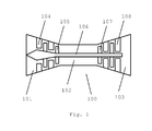
- FIG. 1 shows in a purely schematic way a representation of a turbomachine in the form of a gas turbine 100 with a compressor 101, a combustion chamber 102 and a turbine 103.
- the compressor 101 the sucked air is compressed by the annularly arranged vanes 104 and blades 105 and in the combustion chamber 102 is pressed where it is ignited together with the fuel, so that the exhaust gases flowing out of the combustion chamber in the turbine can drive the blades 106 which between respective guide vanes 108 on a rotatable Shaft 106 are arranged, which simultaneously drives the blades 105 of the compressor.
- the seal carrier according to the invention can be arranged on vanes of a row of guide vanes, as has been described for example with respect to the gas turbine 100.
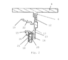
- the Fig. 2 shows a seal carrier 17 made of a TiAl material, such as a TiAl alloy based on y - Titanaluminid formed integrally or segmentally as a ring, wherein the representation of Fig. 2 only shows a cross section through a part of the ring.
- a TiAl material such as a TiAl alloy based on y - Titanaluminid formed integrally or segmentally as a ring, wherein the representation of Fig. 2 only shows a cross section through a part of the ring.
- the seal carrier 17 has at its radially outer end on a connecting portion 12, with which the seal carrier 17 is arranged in a plurality of blade roots 6 of a guide vane arranged together vanes, wherein in the Fig. 2 has been dispensed with the representation of the vanes and only the inner shroud 4 a vane or the vane ring is shown.
- a locating portion 13 which serves to provide a seal 18 which cooperates with a rotating sealing surface of an adjacent bucket ring.
- the rotating sealing surface (not shown) may be suitably disposed on the rotor or disc of the adjacent blade ring.
- the seal 18 is formed as a brush seal, which is held in the arrangement region 13 of the seal carrier 17 via hook rings 20, 21.
- the arrangement portion 13 a ring nozzle 14, which serves as a stop surface for the hook rings 20, 21 and the seal 18, and an axially extending holding portion 15, which serves to receive a clamping ring 16, the seal 18 with the hook rings 20, 21 opposite the ring nozzle 14 holds.
- a honeycomb seal 8 as shown in FIG Fig. 1 is shown arranged.
- the ring stub 14 can be dispensed with and the axially extending holding section 15 can serve as a surface for arranging the honeycomb seal 8.
- an axially projecting Barrier portion 19 is formed, which is provided for cooperation with a correspondingly formed member of an adjacent blade row to prevent a direct radial outflow of the hot gas from the flow channel into the radially inner housing structure.
- the radially projecting locking portion is in the embodiment shown the Fig. 2 formed step-shaped and has a plurality of S-shaped curved portions 22 in order to provide a higher flow resistance for gas flowing past it.
- the seal carrier 17 is manufactured in one piece from a TiAl material, such as, for example, a y-TiAl alloy with alloy constituents of niobium and / or molybdenum, the production being able to take place via a casting technology or forging route. In both cases, however, after the production of a near-net shape semi-finished product, the surface area is removed by machining in order to remove critical marginal areas of the material, to provide a smooth and clean surface and to ensure the possibility of a reliable defect inspection of the component.
- a TiAl material such as, for example, a y-TiAl alloy with alloy constituents of niobium and / or molybdenum
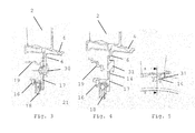
- FIGS. 3 to 9 show various embodiments of a seal carrier 17 and in particular the various possibilities for attaching a corresponding seal carrier or seal carrier ring on the blade roots 6 of vanes 2 and a row of vanes, wherein suitable connecting elements are integrally formed in the seal carrier 17. Since the embodiments of the seal carrier of the FIGS. 3 to 9 essentially the embodiment of the FIG. 2 are identical, identical or similar components are provided with identical reference numerals and it is dispensed with a repeated description of the identical components.
- FIG. 3 shows a first embodiment for arranging a seal carrier 17 on blade roots 6.
- the seal carrier 17 is connected via a plurality of distributed over the circumference of the seal carrier ring rivet 30 with the blade roots 6, so that both in the seal carrier 17, and in the blade roots 6 corresponding openings for implementation the rivets are provided.
- sliding blocks 31 are integrated in the seal carrier, each of which is formed by a spaced from the seal carrier plate plate defining a gap between the ring main body and the plate of the sliding block, can engage in the projections 14 of a blade root 6, so that an axial securing given is.
- the FIGS. 4 and 5 where the FIG. 5 the section line AA indicates that in FIG. 4 is shown, two projections 14 are provided, which are arranged to the left and right of a connection of the spaced plate to the main ring of the seal carrier 17.
- a plurality of sliding blocks 31 are provided for the arrangement of the blades 2 on the seal carrier ring 17.
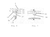
- FIGS. 8 and 9 in which again the FIG. 9 the section line AA indicating the cross-sectional view of FIG. 8 forming holding plates 35 are provided, which in turn are arranged on a rivet 30 on the blade root 6, wherein the holding plates 35 engage in grooves 36 on the seal carrier ring 17 so that here both an axial securing, and a rotation in the circumferential direction of the seal carrier ring 17 is given ,
Landscapes
- Engineering & Computer Science (AREA)
- Mechanical Engineering (AREA)
- General Engineering & Computer Science (AREA)
- Chemical & Material Sciences (AREA)
- Combustion & Propulsion (AREA)
- Structures Of Non-Positive Displacement Pumps (AREA)
- Turbine Rotor Nozzle Sealing (AREA)
Abstract
Description
- Die vorliegende Erfindung betrifft eine Strömungsmaschine, wie beispielsweise eine stationäre Gasturbine oder ein Flugtriebwerk, bzw. einen Dichtungsträger und dessen Herstellung für den Einsatz im Bereich des sogenannten Inner-Air-Seal (IAS) einer Strömungsmaschine.
- Strömungsmaschinen, wie stationäre Gasturbinen und Flugtriebwerke sind seit langem bekannt und werden in vielfältiger Weise eingesetzt. Derartige Strömungsmaschinen weisen einen ringförmigen Strömungskanal auf, in welchem drehbare Laufschaufeln und stationäre Leitschaufeln in Form von Laufschaufelkränzen und Leitschaufelkränzen angeordnet sind. Durch die Anordnung der Laufschaufel- und Leitschaufelkränze wird im Bereich des Verdichters die einströmende Luft verdichtet und im Bereich der Turbine kann durch das ausströmende Heißgas aus der Brennkammer die Strömungsmaschine angetrieben werden. Zur Erzielung eines hohen Wirkungsgrades wird die den Strömungskanal umgebende Gehäusestruktur möglichst so ausgebildet, dass im besten Fall das gesamte, die Strömungsmaschine durchfließende Fluid im Strömungskanal an den Leit- und Laufschaufeln vorbeiströmen muss und radiale Gasverluste vermieden werden. Entsprechend ist es bekannt in der Gehäusestruktur sogenannte Inner- und Outer-Air-Seals als radial innen und radial außen liegende Dichtungen für das Strömungsfluid vorzusehen.
- Für den Turbinenbereich ist in der
DE 10 2008 048 006 A1 ein Beispiel für eine Dichtungsanordnung im Bereich des Inner-Air-Seal (IAS) beschrieben, das auch in der beigefügtenFigur 1 dargestellt ist. DieFig. 1 zeigt hierbei in einem Schnitt entlang der axialen Richtung der Strömungsmaschine eine erste Laufschaufelreihe 1 sowie einen Leitschaufelkranz 2 und eine weitere Laufschaufelreihe 3. An den Laufschaufeln ist ein inneres Deckband 5 angeordnet und an den Leitschaufeln ein inneres Deckband 4, die zusammen die radial innere Begrenzungswand des Strömungskanals bilden. Durch die zwischen den Lauf- und Leitschaufeln gegebenen Spalte kann jedoch Heißgas aus dem Strömungskanal radial entweichen, sodass in der radial inneren Gehäusestruktur eine Dichtungsanordnung vorgesehen ist, deren Dichtung 8 an den Schaufelfüßen 6 der Leitschaufeln 2 mit einem Dichtungsträger 7 angeordnet ist. - An dem Dichtungsträger 7 ist zum einen ein sogenanntes Deckelelement 9 vorgesehen, welches mit einem axial hervorstehenden Bereich des Laufschaufelkranzes 1 eine sogenannte Labyrinthdichtung bildet, um unmittelbares Eindringen von Heißgas aus dem Strömungskanal in den Hohlraum der Gehäusestruktur zu vermeiden. Darüber hinaus ist an dem Dichtungsträger 7 eine Wabendichtung 8 vorgesehen, welche im Eingriff mit einer sich mit dem Laufschaufelkranz 3 mitdrehenden Dichtungsstruktur 10 ist.
- Obwohl eine derartige Dichtung im Bereich der radial inneren Gehäusestruktur ihre Dichtungsaufgaben zuverlässig erfüllt, besteht weiter Verbesserungsbedarf, da insbesondere bei Flugtriebwerken ein beständiges Ziel darin besteht, das Gewicht der Strömungsmaschine zu reduzieren.
- Es ist deshalb Aufgabe der vorliegenden Erfindung eine Strömungsmaschine und insbesondere einen Dichtungsträger für ein Inner-Air-Seal (IAS) bereitzustellen, welche eine sichere und zuverlässige Abdichtung der radial inneren Gehäusestruktur gegenüber Heißgas aus dem Strömungskanal des Turbinenbereichs der Strömungsmaschine gewährleistet, aber eine Gewichtsreduzierung der Strömungsmaschine ermöglicht.
- Diese Aufgabe wird gelöst mit einer Strömungsmaschine mit den Merkmalen des Anspruchs 1 sowie einem Verfahren zur Herstellung eines Dichtungsträgers mit den Merkmalen des Anspruchs 8. Vorteilhafte Ausgestaltungen sind Gegenstand der abhängigen Ansprüche.
- Die vorliegende Erfindung schlägt vor, den Dichtungsträger für die Dichtung einer Inner-Air-Seal aus einem intermetallischen Werkstoff, insbesondere einem TiAl - Werkstoff herzustellen, da intermetallische Werkstoffe und besonders TiAl - Werkstoffe ein niedriges spezifisches Gewicht aufweisen, aber gleichzeitig die Anforderungen an Temperaturbeständigkeit und Festigkeit erfüllen können, um so das Gewicht einer Strömungsmaschine und insbesondere eines Flugtriebwerks zu reduzieren. Insbesondere schlägt die vorliegende Erfindung vor, den Dichtungsträger zunächst zu einem Halbzeug zu gießen oder zu schmieden, um anschließend Randzonen des Halbzeugs vollständig zu entfernen, wobei insbesondere eine mechanische Bearbeitung, wie eine spanabhebende Bearbeitung eingesetzt werden kann. Dadurch können kritische Randzonen des Materials abgetragen werden und es kann eine definierte einheitliche Oberfläche erzeugt werden, die eine hundertprozentige Bauteilprüfung ermöglicht. Auf diese Weise kann den Sicherheitsaspekten für einen sicheren und zuverlässigen Betrieb der Strömungsmaschine Rechnung getragen werden.
- Unter einem intermetallischen Werkstoff wird ein Werkstoff verstanden, der mindestens eine intermetallische Phase in seinem Gefüge aufweist, wobei insbesondere der überwiegende Anteil (bezogen auf das Volumen oder Gewicht) des Gefüges aus intermetallischen Phasen gebildet wird. Insbesondere kann der intermetallische Werkstoff nahezu vollständig aus einer oder mehreren intermetallischen Phasen aufgebaut sein, wenn beispielsweise die intermetallischen Phasen einen hohen Homogenitätsbereich im Phasendiagramm aufweist, so dass in einem weiten Bereich Legierungsbestandteile aufgenommen werden können. Beispiele hierfür sind Werkstoffe auf Basis von Titanaluminiden, die bei der vorliegenden Erfindung bevorzugt eingesetzt werden können.
- Unter intermetallischen Phasen wird eine homogene chemische Verbindung aus zwei oder mehr Metallen verstanden, die neben einer reinen metallischen Bindung Anteile weiterer Bindungsarten, wie kovalente Bindungen oder lonenbindungen, also keramischer Bindungstypen, aufweisen, was in einer besonders hohen Festigkeit der Gitterstruktur und somit des Materials resultiert. Titanaluminide, aber auch Eisenaluminide oder andere intermetallische Werkstoffe weisen daher hohe Festigkeiten bei gleichzeitig niedrigem spezifischem Gewicht aus, und sind deshalb für die vorliegende Erfindung besonders, aber nicht ausschließlich geeignet.
- Deshalb können für die vorliegende Erfindung TiAl - Werkstoffe zur Bildung des Dichtungsträgers eingesetzt werden. Unter einem TiAl - Werkstoff wird im Rahmen der vorliegenden Erfindung jeder Werkstoff verstanden, dessen anteilsmäßig größten Bestandteile Titan und Aluminium sind. Der TiAl - Werkstoff kann somit insbesondere aus einem Titanaluminid gebildet sein und ein Titanaluminid, wie beispielsweise y - TiAl oder α2- Ti3Al umfassen. Insbesondere kann es sich um eine TiAl - Legierung auf Basis eines Titanaluminids, wie beispielsweise von y - TiAl handeln, bei welchem geeignete Legierungsbestandteile zulegiert sind. Insbesondere kann es sich um eine sogenannte TNM- oder TNB-Legierung handeln, die Anteile an Niob und/oder Molybdän umfasst.
- Der Dichtungsträger kann als einstückiger Ring oder mehrteilig aus mehreren Ringsegmenten gebildet werden, die dann zu einem Ring bzw. Kranz ähnlich dem Leitschaufelkranz zusammengesetzt werden.
- Zur Anordnung an dem Leitschaufelkranz kann der Dichtungsträger an seinem radial äußeren Ende einen Verbindungsbereich aufweisen, während am radial inneren Ende ein Anordnungsbereich zur Anordnung der Dichtung vorgesehen ist.
- Als Dichtung kommen verschiedene Dichtungen in Frage, und zwar beispielsweise Wabendichtungen, die in dem Anordnungsbereich des Dichtungsträgers abgeschieden werden können. Alternativ ist es auch möglich eine Bürstendichtung vorzusehen, sodass im Anordnungsbereich ein entsprechendes Bürstenelement befestigt werden kann.
- Zusätzlich kann der Dichtungsträger weitere Funktionalitäten aufweisen, wie beispielsweise einen weiteren Sperrabschnitt, um mit einem benachbarten Laufschaufelkranz das Eindringen von Heißgas in die Gehäusestruktur zu vermeiden. Hierzu kann zwischen dem radial inneren Ende und dem radial äußeren Ende des Dichtungsträgers ein axial vorstehender Sperrabschnitt ausgebildet sein, der zur Erhöhung des Fließwiderstandes für Heißgas eine stufenförmige Form mit mehreren S-förmigen Krümmungen aufweisen kann.
- Bei der vorliegenden Beschreibung beziehen sich die Angaben radial und axial auf den Strömungskanal, sodass eine axiale Richtung entlang der Strömungsrichtung im Strömungskanal verläuft während eine radiale Richtung quer dazu verläuft.
- Darüber hinaus wird bei den Bauteilen, die den Strömungskanal begrenzen, von einer Gehäusestruktur gesprochen, auch wenn die Komponenten, wie beispielsweise die Deckbänder der Leit- und Laufschaufeln, an den entsprechenden Leit- oder Laufschaufelkränzen angeordnet sind.
- Die beigefügten Zeichnungen zeigen in rein schematischer Weise in
- Fig. 1
- eine Darstellung einer Strömungsmaschine, bei der die vorliegende Erfindung eingesetzt werden kann;
- Fig. 2
- eine teilweise Schnittansicht eines erfindungsgemäßen Dichtungsträgers;
- Fig. 3
- eine Schnittdarstellung ähnlich der
Figur 2 einer weiteren Ausführungsform eines Dichtungsträgers; - Fig. 4
- eine Schnittdarstellung einer weiteren Ausführungsform eines Dichtungsträgers ähnlich den
Figuren 2 und3 ; - Fig. 5
- eine teilweise Seitenansicht der Anordnung aus Leitschaufel und Dichtungsträger aus
Figur 4 ; - Fig. 6
- eine weitere Schnittdarstellung ähnlich den
Figuren 2 bis 4 einer weiteren Ausführungsform eines Dichtungsträgers; - Fig. 7
- eine Seitenansicht der Anordnung aus Leitschaufelfuß und Dichtungsträger aus der
Figur 6 ; - Fig. 8
- ein weiteres Ausführungsbeispiel eines Dichtungsträgers in einer Schnittansicht ähnlich den Darstellungen der
Figuren 2 ,3 ,4 und6 ; - Fig. 9
- eine Seitenansicht der Anordnung aus Leitschaufelfuß und Dichtungsträger aus
Figur 8 ; und in - Fig. 10
- einen teilweisen Längsschnitt durch eine Strömungsmaschine entlang der axialen Richtung zur Darstellung eines Dichtungsträgers nach dem Stand der Technik.
- Weitere Vorteile, Kennzeichen und Merkmale der vorliegenden Erfindung werden bei der nachfolgenden detaillierten Beschreibung eines Ausführungsbeispiels anhand der beigefügten Zeichnungen deutlich. Allerdings ist die Erfindung nicht auf dieses Ausführungsbeispiel beschränkt.
- Die
Figur 1 zeigt in einer rein schematischen Weise eine Darstellung einer Strömungsmaschine in Form einer Gasturbine 100 mit einem Kompressor bzw. Verdichter 101, einer Brennkammer 102 und einer Turbine 103. Im Verdichter 101 wird die angesaugte Luft durch die kranzförmig angeordneten Leitschaufeln 104 und Laufschaufeln 105 komprimiert und in die Brennkammer 102 gepresst, wo sie zusammen mit dem Treibstoff gezündet wird, sodass die aus der Brennkammer ausströmenden Verbrennungsgase in der Turbine die Laufschaufeln 106 antreiben können, die zwischen entsprechenden Leitschaufeln 108 an einer drehbaren Welle 106 angeordnet sind, welche gleichzeitig die Laufschaufeln 105 des Verdichters antreibt. Wie bereits im Zusammenhang mit derFigur 10 bei der Beschreibung des Stands der Technik angegeben worden ist, kann der erfindungsgemäße Dichtungsträger an Schaufelfüßen einer Leitschaufelreihe angeordnet sein, wie sie beispielsweise in Bezug auf die Gasturbine 100 beschrieben worden ist. - Die
Fig. 2 zeigt einen Dichtungsträger 17 aus einem TiAl - Werkstoff, wie beispielsweise einer TiAl - Legierung auf Basis von y - Titanaluminid, der einstückig oder segmentweise als Ring ausgebildet ist, wobei die Darstellung derFig. 2 lediglich einen Querschnitt durch einen Teil des Ringes zeigt. - Der Dichtungsträger 17 weist an seinem radial äußeren Ende einen Verbindungsbereich 12 auf, mit dem der Dichtungsträger 17 in mehreren Schaufelfüßen 6 der zu einem Leitschaufelkranz zusammen angeordneten Leitschaufeln angeordnet ist, wobei in der
Fig. 2 auf die Darstellung der Leitschaufeln verzichtet worden ist und lediglich das innere Deckband 4 einer Leitschaufel bzw. des Leitschaufelkranzes gezeigt ist. - Am gegenüberliegenden inneren radialen Ende des Dichtungsträgers 17 ist ein Anordnungsbereich 13 vorgesehen, der zur Anordnung einer Dichtung 18 dient, welche mit einer rotierenden Dichtfläche eines benachbarten Laufschaufelkranzes zusammenwirkt. Die rotierende Dichtfläche (nicht gezeigt) kann in geeigneter Weise an dem Rotor bzw. der Scheibe des benachbarten Laufschaufelkranzes angeordnet sein.
- Im gezeigten Ausführungsbeispiel der
Fig. 2 ist die Dichtung 18 als Bürstendichtung ausgebildet, die über Hakenringe 20, 21 in dem Anordnungsbereich 13 des Dichtungsträgers 17 gehalten ist. Hierzu weist der Anordnungsbereich 13 einen Ringstutzen 14, der als Anschlagfläche für die Hakenringe 20, 21 bzw. die Dichtung 18 dient, sowie einen axial verlaufenden Halteabschnitt 15 auf, der zur Aufnahme eines Klemmrings 16 dient, der die Dichtung 18 mit den Hakenringen 20, 21 gegenüberliegend dem Ringstutzen 14 hält. - Anstelle der Bürstendichtung 18 kann jedoch am Anordnungsbereich 13 auch eine Wabendichtung 8, wie sie in
Fig. 1 dargestellt ist, angeordnet werden. Hierzu kann im Anordnungsbereich 13 auf den Ringstutzen 14 verzichtet und der axial sich erstreckende Halteabschnitt 15 als Fläche zur Anordnung der Wabendichtung 8 dienen. - Zwischen dem radial äußeren Verbindungsbereich 12 und dem radial inneren Anordnungsbereich 13 ist bei der Ausführungsform des Dichtungsträgers 17 der
Fig. 2 ein axial vorstehender Sperrabschnitt 19 ausgebildet, der zum Zusammenwirken mit einem entsprechend ausgebildeten Bauteil einer benachbarten Laufschaufelreihe vorgesehen ist, um ein direktes radiales Ausströmen des Heißgases aus dem Strömungskanal in die radial innere Gehäusestruktur zu verhindern. - Der radial vorstehende Sperrabschnitt ist bei dem gezeigten Ausführungsbeispiel der
Fig. 2 stufenförmig ausgebildet und weist mehrere S-förmig gekrümmte Abschnitte 22 auf, um für daran vorbei strömendes Gas einen höheren Strömungswiderstand bereitzustellen. - Der Dichtungsträger 17 ist einstückig aus einem TiAl - Werkstoff, wie beispielsweise einer y - TiAl-Legierung mit Legierungsbestandteilen aus Niob und/oder Molybdän gefertigt, wobei die Herstellung über eine gießtechnische oder schmiedetechnische Route erfolgen kann. In beiden Fällen wird jedoch nach der Herstellung eines endkonturnahen Halbzeugs der Oberflächenbereich durch Bearbeitung entfernt, um kritische Randbereiche des Materials abzutragen, eine glatte und saubere Oberfläche bereit zu stellen und die Möglichkeit einer zuverlässigen Fehlerprüfung des Bauteils zu gewährleisten.
- Damit ist es möglich leichte Titanaluminide als Dichtungsträger für eine Dichtung im Bereich der sogenannten Inner-Air-Seal (IAS) einer Strömungsmaschine einzusetzen, ohne die Sicherheitsanforderungen an einen zuverlässigen und fehlerfreien Betrieb der Strömungsmaschine zu beeinträchtigen.
- Die
Figuren 3 bis 9 zeigen verschiedene Ausführungsformen eines Dichtungsträgers 17 und insbesondere die verschiedenen Möglichkeiten zur Anbringung eines entsprechenden Dichtungsträgers bzw. Dichtungsträgerrings an den Schaufelfüßen 6 von Leitschaufeln 2 bzw. einer Leitschaufelreihe, wobei geeignete Verbindungselemente integral in dem Dichtungsträger 17 ausgebildet sind. Da die Ausführungsformen des Dichtungsträgers derFiguren 3 bis 9 im Wesentlichen der Ausführungsform derFigur 2 entsprechen, sind gleiche oder ähnliche Komponenten mit identischen Bezugszeichen versehen und es wird auf eine wiederholte Beschreibung der identischen Komponenten verzichtet. - Die
Figur 3 zeigt eine erste Ausführungsform zur Anordnung eines Dichtungsträgers 17 an Schaufelfüßen 6. Der Dichtungsträger 17 ist über mehrere über den Umfang des Dichtungsträgerrings verteilte Nietverbindungen 30 mit den Schaufelfüßen 6 verbunden, sodass sowohl in dem Dichtungsträger 17, als auch in den Schaufelfüßen 6 entsprechende Öffnungen zur Durchführung der Nieten vorgesehen sind. - Bei der Ausführungsform der
Figuren 4 und 5 sind im Dichtungsträger 17 sogenannte Gleitsteine 31 integriert, von denen jeder durch eine beabstandet von dem Dichtungsträgerring angeordnete Platte gebildet ist, die einen Zwischenraum zwischen dem Ringhauptkörper und der Platte des Gleitsteins definiert, in die Vorsprünge 14 eines Schaufelfußes 6 eingreifen können, sodass eine axiale Sicherung gegeben ist. Bei dem gezeigten Ausführungsbeispiel derFiguren 4 und 5 , wobei dieFigur 5 die Schnittlinie A-A angibt, die inFigur 4 gezeigt ist, sind zwei Vorsprünge 14 vorgesehen, die links und rechts neben einer Verbindung der beabstandeten Platte zum Hauptring des Dichtungsträgers 17 angeordnet werden. Entlang des Umfangs des ringförmigen Dichtungsträgers 17 sind mehrere Gleitsteine 31 zur Anordnung der Laufschaufeln 2 an dem Dichtungsträgerring 17 vorgesehen. - Bei der Ausführungsform der
Figuren 6 und 7 , bei denen in der Ansicht derFigur 7 wiederum die Schnittlinie A-A, die inFigur 6 dargestellt ist, angegeben ist, sind entlang des Umfangs des Dichtungsträgerrings 17 sogenannte Nutensteine 34 ausgebildet, in die Nutenplatten 33 eingreifen können, welche wiederum über jeweils eine Nietverbindung 30 mit dem Schaufelfuß 6 eines Leitschaufelkranzes verbunden sind. Durch die Nutenplatte 33 ist eine axiale Sicherung gegeben und durch die Nutensteine 34, die in die Nut der Nutenplatte 33 eingreifen, ist zusätzlich eine Verdrehsicherung in Richtung des Ringumfangs des Dichtungsträgerrings 17 gegeben. - Bei der Ausführungsform der
Figuren 8 und 9 , bei denen wiederum dieFigur 9 die Schnittlinie A-A angibt, die die Querschnittsansicht derFigur 8 bildet, sind Halteplatten 35 vorgesehen, die wiederum über eine Nietverbindung 30 am Schaufelfuß 6 angeordnet sind, wobei die Halteplatten 35 in Nuten 36 am Dichtungsträgerring 17 eingreifen, sodass auch hier sowohl eine axiale Sicherung, als auch eine Verdrehsicherung in Umfangsrichtung des Dichtungsträgerrings 17 gegeben ist. - Obwohl die vorliegende Erfindung anhand des Ausführungsbeispiels detailliert beschrieben worden ist, ist die Erfindung nicht auf dieses Ausführungsbeispiel beschränk, sondern es sind vielmehr Abwandlungen in der Weise möglich, dass einzelne Merkmale weggelassen oder andersartige Kombinationen von Merkmalen verwirklicht werden, sofern der Schutzbereich der beigefügten Ansprüche nicht verlassen wird. Die vorliegende Offenbarung umfasst sämtliche Kombinationen der vorgestellten Einzelmerkmale.
Claims (10)
- Strömungsmaschine mit einem ringförmigen Strömungskanal und einer den Strömungskanal umgebenden Gehäusestruktur und einer Vielzahl von Leitschaufeln und Laufschaufeln, die in dem Strömungskanal angeordnet sind, wobei die Laufschaufeln drehbar in der Gehäusestruktur aufgenommen sind, während die Leitschaufeln in der Gehäusestruktur ortsfest sind, und wobei mehrere Leitschaufeln einen ringförmigen Leitschaufelkranz ausbilden, und wobei die Gehäusestruktur im Bereich der radial inneren Strömungskanalbegrenzung eine Dichtung (18) zur Abdichtung gegen Heißgasaustritt aus dem Strömungskanal aufweist, die über einen Dichtungsträger (17) an Leitschaufelfüßen der Leitschaufeln des Leitschaufelkranzes angeordnet ist und gegen eine drehbare Dichtfläche abdichtet,
dadurch gekennzeichnet, dass
der Dichtungsträger (17) aus einem intermetallischen Werkstoff gebildet ist. - Strömungsmaschine nach Anspruch 1,
dadurch gekennzeichnet, dass
der intermetallische Werkstoff ein TiAl - Werkstoff ist und aus einem Titanaluminid gebildet ist oder ein Titanaluminid umfasst, insbesondere eine TNM - oder TNB - Legierung ist. - Strömungsmaschine nach Anspruch 1 oder 2,
dadurch gekennzeichnet, dass
der Dichtungsträger (17) gegossen oder geschmiedet und oberflächenbearbeitet ist. - Strömungsmaschine nach einem der vorhergehenden Ansprüche,
dadurch gekennzeichnet, dass
der Dichtungsträger (17) als einstückiger Ring oder mehrteilig aus mehreren Ringsegmenten ausgebildet ist. - Strömungsmaschine nach einem der vorhergehenden Ansprüche,
dadurch gekennzeichnet, dass
der Dichtungsträger (17) an einem radial äußeren Ende einen Verbindungsbereich (12) zur Anordnung an den Leitschaufelfüßen und am radial inneren Ende einen Anordnungsbereich (13) zur Anordnung der Dichtung (18) aufweist, wobei zwischen radial innerem Ende und radial äußerem Ende ein axial vorstehender Sperrabschnitt (19) ausgebildet ist. - Strömungsmaschine nach Anspruch 5,
dadurch gekennzeichnet, dass
der Sperrabschnitt (19) mindestens eine, vorzugsweise mehrere S-förmige Krümmungen aufweist. - Strömungsmaschine nach einem der vorhergehenden Ansprüche,
dadurch gekennzeichnet, dass
die Dichtung (18) eine Bürste oder eine Wabenstruktur ist. - Verfahren zur Herstellung eines Dichtungsträgers für eine Strömungsmaschine, insbesondere für eine Strömungsmaschine nach einem der vorhergehenden Ansprüche,
dadurch gekennzeichnet, dass
zunächst ein Halbzeug des Dichtungsträgers aus einem intermetallischen Werkstoff gegossen oder geschmiedet wird und anschließend Randzonen des Halbzeugs vollständig entfernt werden. - Verfahren nach Anspruch 8,
dadurch gekennzeichnet, dass
der intermetallische Werkstoff ein TiAl - Werkstoff ist - Verfahren nach Anspruch 8 oder 9,
dadurch gekennzeichnet, dass
die Entfernung der Randzonen durch mechanische Bearbeitung erfolgt.
Priority Applications (3)
| Application Number | Priority Date | Filing Date | Title |
|---|---|---|---|
| ES13153184T ES2861125T3 (es) | 2013-01-30 | 2013-01-30 | Soporte de juntas de aluminuro de titanio para una turbomáquina |
| EP13153184.0A EP2762684B1 (de) | 2013-01-30 | 2013-01-30 | Dichtungsträger aus titanaluminid für eine strömungsmaschine |
| US14/166,167 US10287989B2 (en) | 2013-01-30 | 2014-01-28 | Seal support of titanium aluminide for a turbomachine |
Applications Claiming Priority (1)
| Application Number | Priority Date | Filing Date | Title |
|---|---|---|---|
| EP13153184.0A EP2762684B1 (de) | 2013-01-30 | 2013-01-30 | Dichtungsträger aus titanaluminid für eine strömungsmaschine |
Publications (2)
| Publication Number | Publication Date |
|---|---|
| EP2762684A1 true EP2762684A1 (de) | 2014-08-06 |
| EP2762684B1 EP2762684B1 (de) | 2021-03-03 |
Family
ID=47681717
Family Applications (1)
| Application Number | Title | Priority Date | Filing Date |
|---|---|---|---|
| EP13153184.0A Not-in-force EP2762684B1 (de) | 2013-01-30 | 2013-01-30 | Dichtungsträger aus titanaluminid für eine strömungsmaschine |
Country Status (3)
| Country | Link |
|---|---|
| US (1) | US10287989B2 (de) |
| EP (1) | EP2762684B1 (de) |
| ES (1) | ES2861125T3 (de) |
Cited By (2)
| Publication number | Priority date | Publication date | Assignee | Title |
|---|---|---|---|---|
| EP3409897A1 (de) | 2017-05-29 | 2018-12-05 | MTU Aero Engines GmbH | Dichtungsanordnung für eine strömungsmaschine, verfahren zur herstellung einer dichtungsanordnung sowie strömungsmaschine |
| CN109277585A (zh) * | 2018-11-30 | 2019-01-29 | 中国航发沈阳黎明航空发动机有限责任公司 | 一种Ti3Al合金导叶内环车削加工方法 |
Families Citing this family (5)
| Publication number | Priority date | Publication date | Assignee | Title |
|---|---|---|---|---|
| DE102016202519A1 (de) * | 2016-02-18 | 2017-08-24 | MTU Aero Engines AG | Leitschaufelsegment für eine Strömungsmaschine |
| DE102017209420A1 (de) * | 2017-06-02 | 2018-12-06 | MTU Aero Engines AG | Dichtungsanordnung mit angeschweißtem Dichtungsblech, Strömungsmaschine und Herstellungsverfahren |
| DE102020202862A1 (de) | 2020-03-06 | 2021-09-09 | MTU Aero Engines AG | Dichtungsvorrichtung für eine Strömungsmaschine, Dichtungsträgerringelement für eine Dichtungsvorrichtung und Strömungsmaschine |
| DE102024112887A1 (de) | 2024-05-08 | 2025-11-13 | MTU Aero Engines AG | Dichtungsanordnung für eine Strömungsmaschine, Dichtungsträgerelement für die Dichtungsanordnung, Leitschaufelelement und Strömungsmaschine |
| CN118653887B (zh) * | 2024-06-12 | 2025-12-30 | 中国航发沈阳发动机研究所 | 一种高压涡轮导向器内支承结构 |
Citations (4)
| Publication number | Priority date | Publication date | Assignee | Title |
|---|---|---|---|---|
| DE102006004090A1 (de) * | 2006-01-28 | 2007-08-02 | Mtu Aero Engines Gmbh | Leitschaufelsegment einer Gasturbine |
| EP2060741A2 (de) * | 2007-11-19 | 2009-05-20 | Rolls-Royce plc | Turbinenanordnung |
| DE102008048006A1 (de) | 2008-09-19 | 2010-03-25 | Mtu Aero Engines Gmbh | Wellenleistungstriebwerk |
| US20110193293A1 (en) * | 2010-02-10 | 2011-08-11 | Rolls-Royce Plc | Seal arrangement |
Family Cites Families (8)
| Publication number | Priority date | Publication date | Assignee | Title |
|---|---|---|---|---|
| US5096376A (en) * | 1990-08-29 | 1992-03-17 | General Electric Company | Low windage corrugated seal facing strip |
| US5215435A (en) * | 1991-10-28 | 1993-06-01 | General Electric Company | Angled cooling air bypass slots in honeycomb seals |
| US5522698A (en) * | 1994-04-29 | 1996-06-04 | United Technologies Corporation | Brush seal support and vane assembly windage cover |
| EP1508672A1 (de) * | 2003-08-21 | 2005-02-23 | Siemens Aktiengesellschaft | Segmentierter Befestigungsring für eine Turbine |
| DE102007051499A1 (de) * | 2007-10-27 | 2009-04-30 | Mtu Aero Engines Gmbh | Werkstoff für ein Gasturbinenbauteil, Verfahren zur Herstellung eines Gasturbinenbauteils sowie Gasturbinenbauteil |
| US8079803B2 (en) * | 2008-06-30 | 2011-12-20 | Mitsubishi Heavy Industries, Ltd. | Gas turbine and cooling air supply structure thereof |
| US8534673B2 (en) * | 2010-08-20 | 2013-09-17 | Mitsubishi Power Systems Americas, Inc. | Inter stage seal housing having a replaceable wear strip |
| US8899924B2 (en) * | 2011-06-20 | 2014-12-02 | United Technologies Corporation | Non-mechanically fastened TOBI heat shield |
-
2013
- 2013-01-30 EP EP13153184.0A patent/EP2762684B1/de not_active Not-in-force
- 2013-01-30 ES ES13153184T patent/ES2861125T3/es active Active
-
2014
- 2014-01-28 US US14/166,167 patent/US10287989B2/en not_active Expired - Fee Related
Patent Citations (4)
| Publication number | Priority date | Publication date | Assignee | Title |
|---|---|---|---|---|
| DE102006004090A1 (de) * | 2006-01-28 | 2007-08-02 | Mtu Aero Engines Gmbh | Leitschaufelsegment einer Gasturbine |
| EP2060741A2 (de) * | 2007-11-19 | 2009-05-20 | Rolls-Royce plc | Turbinenanordnung |
| DE102008048006A1 (de) | 2008-09-19 | 2010-03-25 | Mtu Aero Engines Gmbh | Wellenleistungstriebwerk |
| US20110193293A1 (en) * | 2010-02-10 | 2011-08-11 | Rolls-Royce Plc | Seal arrangement |
Cited By (3)
| Publication number | Priority date | Publication date | Assignee | Title |
|---|---|---|---|---|
| EP3409897A1 (de) | 2017-05-29 | 2018-12-05 | MTU Aero Engines GmbH | Dichtungsanordnung für eine strömungsmaschine, verfahren zur herstellung einer dichtungsanordnung sowie strömungsmaschine |
| US10808561B2 (en) | 2017-05-29 | 2020-10-20 | MTU Aero Engines AG | Seal arrangement for a turbomachine, method for manufacturing a seal arrangement and turbomachine |
| CN109277585A (zh) * | 2018-11-30 | 2019-01-29 | 中国航发沈阳黎明航空发动机有限责任公司 | 一种Ti3Al合金导叶内环车削加工方法 |
Also Published As
| Publication number | Publication date |
|---|---|
| ES2861125T3 (es) | 2021-10-05 |
| US20140227080A1 (en) | 2014-08-14 |
| EP2762684B1 (de) | 2021-03-03 |
| US10287989B2 (en) | 2019-05-14 |
Similar Documents
| Publication | Publication Date | Title |
|---|---|---|
| EP3409897B1 (de) | Dichtungsanordnung für eine strömungsmaschine, verfahren zur herstellung einer dichtungsanordnung sowie strömungsmaschine | |
| EP2762684B1 (de) | Dichtungsträger aus titanaluminid für eine strömungsmaschine | |
| DE102012201050B4 (de) | Dichtungsanordnung, Verfahren sowie Strömungsmaschine | |
| EP2693061B1 (de) | Verdichterschaufel einer Gasturbine sowie Verfahren zu deren Herstellung | |
| EP2647795A1 (de) | Dichtungssystem für eine Strömungsmaschine | |
| DE102006004090A1 (de) | Leitschaufelsegment einer Gasturbine | |
| EP3054106B1 (de) | Gasturbinenbauteil | |
| EP2728122B1 (de) | Dichtungsträgerfixierung für eine Strömungsmaschine | |
| EP2960555B1 (de) | Bürstendichtungssystem zum abdichten eines spalts zwischen relativ zueinander bewegbaren bauteilen einer strömungsmaschine | |
| EP3034781B1 (de) | Abgasturbolader | |
| EP3034788B1 (de) | Kompressorschaufel einer gasturbine | |
| EP4219897A1 (de) | Rotor mit einem wuchtflansch, rotoranordnung mit zumindest einem rotor und strömungsmaschine mit zumindest einem rotor oder mit einer rotoranordnung | |
| EP3034837B1 (de) | Kühlluftzufuhrvorrichtung für eine Gasturbine | |
| EP3492704B1 (de) | Modul für eine strömungsmaschine | |
| EP3483399A1 (de) | Dichtungsanordnung für eine strömungsmaschine, verfahren zur herstellung einer dichtungsanordnung sowie strömungsmaschine | |
| EP2716874A1 (de) | Leitschaufelkranz, Montageverfahren und Strömungsmaschine | |
| EP2378066A2 (de) | Rotor für eine Strömungsmaschine | |
| WO2010099781A2 (de) | Rotor für eine strömungsmaschine | |
| EP2394028B1 (de) | Abdichtvorrichtung an dem Schaufelschaft einer Rotorstufe einer axialen Strömungsmaschine und ihre Verwendung | |
| EP2696039B1 (de) | Gasturbinenstufe | |
| DE60002781T2 (de) | Nabe-Achse Verbindung | |
| EP3425170A2 (de) | Turbomaschinen-dichtungselement | |
| DE102009052314A1 (de) | Dichtanordnung für eine Gasturbine und eine derartige Gasturbine | |
| EP3514333B1 (de) | Rotorschaufeldeckband für eine strömungsmaschine, rotorschaufel, verfahren zum herstellen eines rotorschaufeldeckbands und einer rotorschaufel | |
| EP3312388A1 (de) | Pultdach dichtfin |
Legal Events
| Date | Code | Title | Description |
|---|---|---|---|
| PUAI | Public reference made under article 153(3) epc to a published international application that has entered the european phase |
Free format text: ORIGINAL CODE: 0009012 |
|
| 17P | Request for examination filed |
Effective date: 20130130 |
|
| AK | Designated contracting states |
Kind code of ref document: A1 Designated state(s): AL AT BE BG CH CY CZ DE DK EE ES FI FR GB GR HR HU IE IS IT LI LT LU LV MC MK MT NL NO PL PT RO RS SE SI SK SM TR |
|
| AX | Request for extension of the european patent |
Extension state: BA ME |
|
| RAP1 | Party data changed (applicant data changed or rights of an application transferred) |
Owner name: MTU AERO ENGINES GMBH |
|
| R17P | Request for examination filed (corrected) |
Effective date: 20150120 |
|
| RBV | Designated contracting states (corrected) |
Designated state(s): AL AT BE BG CH CY CZ DE DK EE ES FI FR GB GR HR HU IE IS IT LI LT LU LV MC MK MT NL NO PL PT RO RS SE SI SK SM TR |
|
| RAP1 | Party data changed (applicant data changed or rights of an application transferred) |
Owner name: MTU AERO ENGINES AG |
|
| STAA | Information on the status of an ep patent application or granted ep patent |
Free format text: STATUS: EXAMINATION IS IN PROGRESS |
|
| 17Q | First examination report despatched |
Effective date: 20200316 |
|
| GRAP | Despatch of communication of intention to grant a patent |
Free format text: ORIGINAL CODE: EPIDOSNIGR1 |
|
| STAA | Information on the status of an ep patent application or granted ep patent |
Free format text: STATUS: GRANT OF PATENT IS INTENDED |
|
| INTG | Intention to grant announced |
Effective date: 20200918 |
|
| GRAS | Grant fee paid |
Free format text: ORIGINAL CODE: EPIDOSNIGR3 |
|
| GRAA | (expected) grant |
Free format text: ORIGINAL CODE: 0009210 |
|
| STAA | Information on the status of an ep patent application or granted ep patent |
Free format text: STATUS: THE PATENT HAS BEEN GRANTED |
|
| AK | Designated contracting states |
Kind code of ref document: B1 Designated state(s): AL AT BE BG CH CY CZ DE DK EE ES FI FR GB GR HR HU IE IS IT LI LT LU LV MC MK MT NL NO PL PT RO RS SE SI SK SM TR |
|
| REG | Reference to a national code |
Ref country code: GB Ref legal event code: FG4D Free format text: NOT ENGLISH |
|
| REG | Reference to a national code |
Ref country code: AT Ref legal event code: REF Ref document number: 1367409 Country of ref document: AT Kind code of ref document: T Effective date: 20210315 Ref country code: CH Ref legal event code: EP |
|
| REG | Reference to a national code |
Ref country code: DE Ref legal event code: R096 Ref document number: 502013015525 Country of ref document: DE |
|
| REG | Reference to a national code |
Ref country code: IE Ref legal event code: FG4D Free format text: LANGUAGE OF EP DOCUMENT: GERMAN |
|
| REG | Reference to a national code |
Ref country code: LT Ref legal event code: MG9D |
|
| PG25 | Lapsed in a contracting state [announced via postgrant information from national office to epo] |
Ref country code: LT Free format text: LAPSE BECAUSE OF FAILURE TO SUBMIT A TRANSLATION OF THE DESCRIPTION OR TO PAY THE FEE WITHIN THE PRESCRIBED TIME-LIMIT Effective date: 20210303 Ref country code: FI Free format text: LAPSE BECAUSE OF FAILURE TO SUBMIT A TRANSLATION OF THE DESCRIPTION OR TO PAY THE FEE WITHIN THE PRESCRIBED TIME-LIMIT Effective date: 20210303 Ref country code: HR Free format text: LAPSE BECAUSE OF FAILURE TO SUBMIT A TRANSLATION OF THE DESCRIPTION OR TO PAY THE FEE WITHIN THE PRESCRIBED TIME-LIMIT Effective date: 20210303 Ref country code: GR Free format text: LAPSE BECAUSE OF FAILURE TO SUBMIT A TRANSLATION OF THE DESCRIPTION OR TO PAY THE FEE WITHIN THE PRESCRIBED TIME-LIMIT Effective date: 20210604 Ref country code: BG Free format text: LAPSE BECAUSE OF FAILURE TO SUBMIT A TRANSLATION OF THE DESCRIPTION OR TO PAY THE FEE WITHIN THE PRESCRIBED TIME-LIMIT Effective date: 20210603 Ref country code: NO Free format text: LAPSE BECAUSE OF FAILURE TO SUBMIT A TRANSLATION OF THE DESCRIPTION OR TO PAY THE FEE WITHIN THE PRESCRIBED TIME-LIMIT Effective date: 20210603 |
|
| REG | Reference to a national code |
Ref country code: NL Ref legal event code: MP Effective date: 20210303 |
|
| PG25 | Lapsed in a contracting state [announced via postgrant information from national office to epo] |
Ref country code: LV Free format text: LAPSE BECAUSE OF FAILURE TO SUBMIT A TRANSLATION OF THE DESCRIPTION OR TO PAY THE FEE WITHIN THE PRESCRIBED TIME-LIMIT Effective date: 20210303 Ref country code: PL Free format text: LAPSE BECAUSE OF FAILURE TO SUBMIT A TRANSLATION OF THE DESCRIPTION OR TO PAY THE FEE WITHIN THE PRESCRIBED TIME-LIMIT Effective date: 20210303 Ref country code: RS Free format text: LAPSE BECAUSE OF FAILURE TO SUBMIT A TRANSLATION OF THE DESCRIPTION OR TO PAY THE FEE WITHIN THE PRESCRIBED TIME-LIMIT Effective date: 20210303 Ref country code: SE Free format text: LAPSE BECAUSE OF FAILURE TO SUBMIT A TRANSLATION OF THE DESCRIPTION OR TO PAY THE FEE WITHIN THE PRESCRIBED TIME-LIMIT Effective date: 20210303 |
|
| PG25 | Lapsed in a contracting state [announced via postgrant information from national office to epo] |
Ref country code: NL Free format text: LAPSE BECAUSE OF FAILURE TO SUBMIT A TRANSLATION OF THE DESCRIPTION OR TO PAY THE FEE WITHIN THE PRESCRIBED TIME-LIMIT Effective date: 20210303 |
|
| PG25 | Lapsed in a contracting state [announced via postgrant information from national office to epo] |
Ref country code: SM Free format text: LAPSE BECAUSE OF FAILURE TO SUBMIT A TRANSLATION OF THE DESCRIPTION OR TO PAY THE FEE WITHIN THE PRESCRIBED TIME-LIMIT Effective date: 20210303 Ref country code: EE Free format text: LAPSE BECAUSE OF FAILURE TO SUBMIT A TRANSLATION OF THE DESCRIPTION OR TO PAY THE FEE WITHIN THE PRESCRIBED TIME-LIMIT Effective date: 20210303 Ref country code: CZ Free format text: LAPSE BECAUSE OF FAILURE TO SUBMIT A TRANSLATION OF THE DESCRIPTION OR TO PAY THE FEE WITHIN THE PRESCRIBED TIME-LIMIT Effective date: 20210303 |
|
| PG25 | Lapsed in a contracting state [announced via postgrant information from national office to epo] |
Ref country code: IS Free format text: LAPSE BECAUSE OF FAILURE TO SUBMIT A TRANSLATION OF THE DESCRIPTION OR TO PAY THE FEE WITHIN THE PRESCRIBED TIME-LIMIT Effective date: 20210703 Ref country code: RO Free format text: LAPSE BECAUSE OF FAILURE TO SUBMIT A TRANSLATION OF THE DESCRIPTION OR TO PAY THE FEE WITHIN THE PRESCRIBED TIME-LIMIT Effective date: 20210303 Ref country code: PT Free format text: LAPSE BECAUSE OF FAILURE TO SUBMIT A TRANSLATION OF THE DESCRIPTION OR TO PAY THE FEE WITHIN THE PRESCRIBED TIME-LIMIT Effective date: 20210705 Ref country code: SK Free format text: LAPSE BECAUSE OF FAILURE TO SUBMIT A TRANSLATION OF THE DESCRIPTION OR TO PAY THE FEE WITHIN THE PRESCRIBED TIME-LIMIT Effective date: 20210303 |
|
| REG | Reference to a national code |
Ref country code: DE Ref legal event code: R097 Ref document number: 502013015525 Country of ref document: DE |
|
| PLBE | No opposition filed within time limit |
Free format text: ORIGINAL CODE: 0009261 |
|
| STAA | Information on the status of an ep patent application or granted ep patent |
Free format text: STATUS: NO OPPOSITION FILED WITHIN TIME LIMIT |
|
| PG25 | Lapsed in a contracting state [announced via postgrant information from national office to epo] |
Ref country code: AL Free format text: LAPSE BECAUSE OF FAILURE TO SUBMIT A TRANSLATION OF THE DESCRIPTION OR TO PAY THE FEE WITHIN THE PRESCRIBED TIME-LIMIT Effective date: 20210303 Ref country code: DK Free format text: LAPSE BECAUSE OF FAILURE TO SUBMIT A TRANSLATION OF THE DESCRIPTION OR TO PAY THE FEE WITHIN THE PRESCRIBED TIME-LIMIT Effective date: 20210303 |
|
| 26N | No opposition filed |
Effective date: 20211206 |
|
| PG25 | Lapsed in a contracting state [announced via postgrant information from national office to epo] |
Ref country code: SI Free format text: LAPSE BECAUSE OF FAILURE TO SUBMIT A TRANSLATION OF THE DESCRIPTION OR TO PAY THE FEE WITHIN THE PRESCRIBED TIME-LIMIT Effective date: 20210303 |
|
| PG25 | Lapsed in a contracting state [announced via postgrant information from national office to epo] |
Ref country code: IT Free format text: LAPSE BECAUSE OF FAILURE TO SUBMIT A TRANSLATION OF THE DESCRIPTION OR TO PAY THE FEE WITHIN THE PRESCRIBED TIME-LIMIT Effective date: 20210303 |
|
| PG25 | Lapsed in a contracting state [announced via postgrant information from national office to epo] |
Ref country code: IS Free format text: LAPSE BECAUSE OF FAILURE TO SUBMIT A TRANSLATION OF THE DESCRIPTION OR TO PAY THE FEE WITHIN THE PRESCRIBED TIME-LIMIT Effective date: 20210703 |
|
| REG | Reference to a national code |
Ref country code: DE Ref legal event code: R119 Ref document number: 502013015525 Country of ref document: DE |
|
| PG25 | Lapsed in a contracting state [announced via postgrant information from national office to epo] |
Ref country code: MC Free format text: LAPSE BECAUSE OF FAILURE TO SUBMIT A TRANSLATION OF THE DESCRIPTION OR TO PAY THE FEE WITHIN THE PRESCRIBED TIME-LIMIT Effective date: 20210303 |
|
| REG | Reference to a national code |
Ref country code: CH Ref legal event code: PL |
|
| GBPC | Gb: european patent ceased through non-payment of renewal fee |
Effective date: 20220130 |
|
| REG | Reference to a national code |
Ref country code: BE Ref legal event code: MM Effective date: 20220131 |
|
| PG25 | Lapsed in a contracting state [announced via postgrant information from national office to epo] |
Ref country code: LU Free format text: LAPSE BECAUSE OF NON-PAYMENT OF DUE FEES Effective date: 20220130 Ref country code: GB Free format text: LAPSE BECAUSE OF NON-PAYMENT OF DUE FEES Effective date: 20220130 Ref country code: DE Free format text: LAPSE BECAUSE OF NON-PAYMENT OF DUE FEES Effective date: 20220802 |
|
| PG25 | Lapsed in a contracting state [announced via postgrant information from national office to epo] |
Ref country code: FR Free format text: LAPSE BECAUSE OF NON-PAYMENT OF DUE FEES Effective date: 20220131 Ref country code: BE Free format text: LAPSE BECAUSE OF NON-PAYMENT OF DUE FEES Effective date: 20220131 |
|
| PG25 | Lapsed in a contracting state [announced via postgrant information from national office to epo] |
Ref country code: LI Free format text: LAPSE BECAUSE OF NON-PAYMENT OF DUE FEES Effective date: 20220131 Ref country code: CH Free format text: LAPSE BECAUSE OF NON-PAYMENT OF DUE FEES Effective date: 20220131 |
|
| PG25 | Lapsed in a contracting state [announced via postgrant information from national office to epo] |
Ref country code: IE Free format text: LAPSE BECAUSE OF NON-PAYMENT OF DUE FEES Effective date: 20220130 |
|
| REG | Reference to a national code |
Ref country code: AT Ref legal event code: MM01 Ref document number: 1367409 Country of ref document: AT Kind code of ref document: T Effective date: 20220130 |
|
| PG25 | Lapsed in a contracting state [announced via postgrant information from national office to epo] |
Ref country code: AT Free format text: LAPSE BECAUSE OF NON-PAYMENT OF DUE FEES Effective date: 20220130 |
|
| REG | Reference to a national code |
Ref country code: ES Ref legal event code: FD2A Effective date: 20230428 |
|
| PG25 | Lapsed in a contracting state [announced via postgrant information from national office to epo] |
Ref country code: ES Free format text: LAPSE BECAUSE OF NON-PAYMENT OF DUE FEES Effective date: 20220131 |
|
| PG25 | Lapsed in a contracting state [announced via postgrant information from national office to epo] |
Ref country code: HU Free format text: LAPSE BECAUSE OF FAILURE TO SUBMIT A TRANSLATION OF THE DESCRIPTION OR TO PAY THE FEE WITHIN THE PRESCRIBED TIME-LIMIT; INVALID AB INITIO Effective date: 20130130 |
|
| PG25 | Lapsed in a contracting state [announced via postgrant information from national office to epo] |
Ref country code: MK Free format text: LAPSE BECAUSE OF FAILURE TO SUBMIT A TRANSLATION OF THE DESCRIPTION OR TO PAY THE FEE WITHIN THE PRESCRIBED TIME-LIMIT Effective date: 20210303 Ref country code: CY Free format text: LAPSE BECAUSE OF FAILURE TO SUBMIT A TRANSLATION OF THE DESCRIPTION OR TO PAY THE FEE WITHIN THE PRESCRIBED TIME-LIMIT Effective date: 20210303 |
|
| PG25 | Lapsed in a contracting state [announced via postgrant information from national office to epo] |
Ref country code: MT Free format text: LAPSE BECAUSE OF FAILURE TO SUBMIT A TRANSLATION OF THE DESCRIPTION OR TO PAY THE FEE WITHIN THE PRESCRIBED TIME-LIMIT Effective date: 20210303 |
|
| PG25 | Lapsed in a contracting state [announced via postgrant information from national office to epo] |
Ref country code: TR Free format text: LAPSE BECAUSE OF FAILURE TO SUBMIT A TRANSLATION OF THE DESCRIPTION OR TO PAY THE FEE WITHIN THE PRESCRIBED TIME-LIMIT Effective date: 20210303 |