EP2762425B1 - Dispositif avec galet de transfert pour soulever des produits empilés - Google Patents
Dispositif avec galet de transfert pour soulever des produits empilés Download PDFInfo
- Publication number
- EP2762425B1 EP2762425B1 EP14154025.2A EP14154025A EP2762425B1 EP 2762425 B1 EP2762425 B1 EP 2762425B1 EP 14154025 A EP14154025 A EP 14154025A EP 2762425 B1 EP2762425 B1 EP 2762425B1
- Authority
- EP
- European Patent Office
- Prior art keywords
- mat
- deflection roller
- deflection
- roller pair
- plane
- Prior art date
- Legal status (The legal status is an assumption and is not a legal conclusion. Google has not performed a legal analysis and makes no representation as to the accuracy of the status listed.)
- Active
Links
Images


Classifications
-
- B—PERFORMING OPERATIONS; TRANSPORTING
- B65—CONVEYING; PACKING; STORING; HANDLING THIN OR FILAMENTARY MATERIAL
- B65G—TRANSPORT OR STORAGE DEVICES, e.g. CONVEYORS FOR LOADING OR TIPPING, SHOP CONVEYOR SYSTEMS OR PNEUMATIC TUBE CONVEYORS
- B65G17/00—Conveyors having an endless traction element, e.g. a chain, transmitting movement to a continuous or substantially-continuous load-carrying surface or to a series of individual load-carriers; Endless-chain conveyors in which the chains form the load-carrying surface
- B65G17/12—Conveyors having an endless traction element, e.g. a chain, transmitting movement to a continuous or substantially-continuous load-carrying surface or to a series of individual load-carriers; Endless-chain conveyors in which the chains form the load-carrying surface comprising a series of individual load-carriers fixed, or normally fixed, relative to traction element
- B65G17/123—Conveyors having an endless traction element, e.g. a chain, transmitting movement to a continuous or substantially-continuous load-carrying surface or to a series of individual load-carriers; Endless-chain conveyors in which the chains form the load-carrying surface comprising a series of individual load-carriers fixed, or normally fixed, relative to traction element arranged to keep the load-carriers horizontally during at least a part of the conveyor run
Definitions
- the invention relates to a device for the height transport of stacks.
- Hoist conveyors are known in the art which convey flat lay objects stacked one above the other from a first height to a second height via a transport device.
- the known device comprises a feed plane in which the stacks are fed to a mat element.
- This mat element is usually made flexible and is moved by a transport device.
- Known transport devices have, for example, circumferential belt elements to which the mat element is attached.
- the drive is in operative connection with the belt elements to the mat element of the Feeding level in the discharge level and move back. Since the production speeds of the articles to be transported in stacks from the elevator have substantially increased in the past, the aim is to increase the performance of the elevator.
- the FR 2 756 814 describes a generic device.
- the object of the present invention is to avoid the abovementioned disadvantages, in particular to provide a device for transporting height of stacks, which is increased in their performance for conveying the stacks, without the stack to be transported loses its basic shape.
- the device according to the invention is formed with a drive having a plurality of gear elements, which are in operative connection with the belt elements to move the mat element from the feed plane in the discharge plane and back, wherein the transmission elements are arranged such that a Form lifting zone and a transport zone, wherein the lifting zone between the feed plane and the discharge plane, wherein in the lifting zone, the mat member provides a footprint for the stack, which is substantially perpendicular to the direction of movement of the mat element, and in the transport zone, the footprint of the mat element parallel to Movement direction of the mat element is.
- the drive as a gear element has a lower deflection roller pair in the feed plane and an upper deflection roller pair in the discharge plane
- the drive has at least one transfer roller in the discharge plane, which adjoins the upper deflection roller pair in the direction of movement of the mat element, wherein the upper deflection roller pair is substantially increased in diameter than the transfer roller. Due to the significantly enlarged upper deflection roller pair, higher transport speeds can be achieved both in the transport zone and in the lifting zone. On the other hand, the enlarged diameter acts with respect to the upper deflection roller pair, so that when changing the direction of the mat element from the lifting zone into the transport zone, the forces acting on the mat element, in particular radial accelerations can be kept low.
- the upper deflection roller pair it is conceivable for the upper deflection roller pair to have a first and a second deflection roller, wherein the diameter of the deflection rollers is increased more than approximately 20% to the diameter of the transfer roller, in particular more than approximately 50% increases to the diameter of the transfer roller more preferably about more than about 100% of the diameter of the transfer roller is increased.
- the diameter of the upper pulley pair is at least greater than 250mm.
- the device comprises that the first, the second deflection roller and the transfer roller each have an axis about which the first, the second deflection roller and the transfer roller are rotatably mounted, wherein the axes of the deflection rollers lie on a common horizontal plane, wherein the Axle of the transfer roller is above the horizontal plane, so that there is a horizontal discharge plane.
- the two upper pulleys and the transfer roller are arranged to each other such that a horizontal transport of the mat element is ensured to the deflection of the transfer roller.
- the lower deflection roller pair has a first and a second deflection roller, wherein in particular the diameters of the deflection rollers of the upper and lower Umlenkrollenpackes are the same size.
- the mat member may have two side portions, with two strap members secured to each side portion such that a front and a rear strap member are secured to the first side portion and a front and rear strap members are secured to the second side portion, the strap members of each side portion being spaced apart.
- the mat member may have a rectangular shape or a square shape, with four attachment portions being provided to cause the mat member to be connected to the circulating belt members.
- each of the four strap elements is connected to only one attachment point of the mat element.
- the attachment of each two belt elements on each side region of the mat element has the advantage that the mat element can be reliably moved through the transport zone and the lifting zone, without the mat element can tilt.
- the use of four belt elements also has the advantage that high transport speeds can be achieved, at the same time reliable deflections the gear elements are feasible without the mat element loses its desired position.
- the device according to the invention can be designed such that the front and rear belt element of the first side region are of equal length and that the front and rear belt element of the second side region are of equal length.
- the invention may include that the drive has a lower deflection roller pair in the feed plane and an upper deflection roller pair in the discharge plane, the deflection roller pairs acting as transmission elements.
- the device according to the invention can be designed such that a first deflection roller of the lower pulley pair for the deflection of the front and the rear belt member of the first side region and serves a second pulley of the lower pulley pair for the deflection of the front and rear belt element of the second side area is used.
- a first deflection roller of the upper deflection roller pair is used for the deflection of the front and the rear belt element of the first side region and a second deflection roller of the upper deflection roller pair serves for the deflection of all belt elements.
- the invention may also include that the drive comprises auxiliary rollers as gear elements, on which all are deflected, wherein in particular the auxiliary rollers are arranged between the second deflection roller of the upper deflection roller pair and the first roller of the lower deflection roller pair.
- the auxiliary rollers serve for the mat element to be able to circulate through the transport device, including the belt elements, within the elevator, wherein in the lifting zone of the base area of the mat element the stacks are moved upwards from the unloading plane into the feed plane. Arrived in the discharge level carried over the movement of the mat element, a removal of the stack, which then leave the elevator of the invention.
- the transport direction of the mat element and the stack is perpendicular to the transport direction within the lifting zone.
- the mat element is deflected along one or more gear elements, wherein the mat element is located in the transport zone, in which the footprint of the mat Matt element is parallel to the direction of movement of the mat element. Since it may be necessary in the transport zone for the mat element to undergo further deflections, a corresponding number of auxiliary rollers is provided as the gear elements for this purpose.
- a first deflection roller of the lower deflection roller pair serve for the deflection of the front and the rear belt element of the first side region and serve a second deflection roller of the lower deflection roller pair for the deflection of the front and the rear belt element of the second side region.
- a first deflection roller of the upper deflection roller pair is used for the deflection of the front and the rear belt element of the first side region and a second deflection roller of the upper deflection roller pair for the deflection of the front and the rear belt element of the second side region, wherein at the same time the front and abut the rear belt member of the first side portion of the second pulley of the upper pulley pair.
- the second deflection roller of the upper deflection roller pair is adjoined by the transfer roller, so that the stack can reliably be transferred to a next processing unit.
- a measure improving the invention can provide that a damping element is arranged in the feed plane and / or in the discharge plane, in particular that the damping element is arranged on the frame of the device.
- a significant advantage of the damping element is that it acts on the mat element in such a way that possible forces and / or impulses acting on the mat element do not cause the mat element to vibrate, which triggers disregarding of the stacks to be transported.
- the one or more damping elements advantageously act directly on the mat element and eliminate possible vibrations of the mat element.
- the damping element contacts the mat element while the stacks are transported, wherein advantageously the damping element and the mat element are made of different materials.
- the damping element is formed from a sliding material.
- the embodiment of the damping element made of a plastic can also be advantageous since, in particular, low frictional forces and / or noise develop.
- the damping element can be arranged in the feed plane and / or in the discharge plane. It has been found that, especially in the feed plane, vibrations and / or impulses on the mat element, which disadvantageously change the desired stack shape of the stack to be transported, are also transmitted to the mat element in the discharge plane.
- the rotating belt elements are deflected at defined locations by the gear elements, whereby radial forces, vibrations and / or pulses act on the belt elements, which in turn adversely affect the attached to the belt elements mat element. Since changes in direction of the revolving belt elements are present in particular in the feed plane and in the discharge plane, the use of one or more damping elements at these points is particularly expedient.
- the device for transporting height of stacks may further comprise the damping element being fixed to the frame of the device.
- the damping element may rest against the mat element before the lifting zone and / or after the lifting zone.
- the contact between the damping element and the mat element favors the absorption of any vibrations and / or forces and / or pulses that arise during the deflection of the flexible mat element and / or during the deflection of the belt elements.
- the device according to the invention can have a plurality of damping elements which act on the edge region of the mat element. This means that two or more damping elements simultaneously contact the mat element on a mat element.
- the damping element can act on the standing surface on which the stack can be placed. It is conceivable that the stack is located between the acting damping elements on the base surface, with a sufficiently large distance between the damping element and the stack is present.
- the damping element is movably arranged on the frame, in particular that a drive is provided to bring the damping element to the base of the mat element to the contact.
- the relative position of the damping element with respect to the mat element is adjustable in order to achieve an optimal contact between the damping element and the mat element, which effectively reduces or eliminates vibration on the mat element.
- the device according to the invention may comprise sensor elements which detect the travel path of the damping element and / or the position of the mat element as well as the base surface. The sensor elements can be in data communication with the drive or with a corresponding control, so that the damping element can be optimally moved to the mat element.
- the device according to the invention discloses that the damping element is a rod-like strip and / or rail, which is arranged in particular rigidly and / or immovably to the mat element.
- the formation of the damping element as a rod-like bar or rail has the advantage that a relatively large contact surface can be formed on the part of the damping element, which acts directly on the base surface of the mat element.
- effective vibrations, forces or pulses can be absorbed by such a geometrically shaped damping element.
- the device according to the invention can provide that the damping element is a roller which contacts the mat element and has an axis about which the roller rotates during the movement of the mat element.
- the roller thus rolls off during the movement of the mat element on the base surface of the mat element and can effectively record vibrations, forces or impulses which can act on the mat element, without resulting in a disheveling of the mat element located on the stack.
- the rod-like bar and / or rail which can serve as a damping element
- the roller can be connected to a drive, which ensures that the damping element is arranged movable on the frame.
- the mat element is made of a plurality of rigid mat members, which are arranged adjacent to each other, that in a deflection of the direction of movement of the mat element on the pulleys each mat member to the adjacent mat member is relatively movable.
- the mat member is formed of a plurality of individual mat members which are positioned side by side, wherein upon movement in the lifting zone the mat members are horizontally aligned and form a flat footing for each individual stack. Since the mat members are material-rigid, a deflection of the mat element is excluded. In the deflection areas, the individual mat members move individually around the respective gear elements, wherein the distance to the respective adjacent mat member in the deflection region changes or can change. Outside the deflection areas, the individual mat members to each other on a fixed distance. Thus, higher transport speeds in the transport zone and in the lifting zone are conceivable, so that a disembarking of the stack can be prevented.
- the mat element remains in the horizontal position without the risk of individual elements of the stack shifting or even falling down.
- a planar footprint for the individual stack which can no longer wavy or spherical form during the movement, which is conceivable in the prior art.
- a parcel and / or palletizing quality which increases significantly after the height transport or following the device according to the invention, can be increased.
- the device according to the invention in a palletizing the merging of the individual stacks on a pallet, which in turn is packaged as a unit.
- Another advantage with the use of mat members spaced apart from one another is that during movement of the mat member, it is less prone to vibrate, which may arise during transport of the stacks, for example.
- the mat members may be arranged in the mat element such that in the lifting zone, the mat members are at a distance from one another.
- An advantage of this embodiment is that during movement of the mat member, the clearance helps to create almost no noise between the mat members.
- the distance between the mat members also ensures that during the deflection of the direction of movement of the mat member each mat member can move accordingly to follow the direction of movement of the mat member.
- the distance is between 0.3 mm ⁇ distance ⁇ 5 mm, in particular between 1 mm ⁇ distance ⁇ 3 mm.
- the distance between two mat members is about 2mm.
- the distance depends inter alia on how strongly the transmission elements used initiate a change of direction in the elevator according to the invention.
- the distance between the mat members also depends on the object to be transported in the form of stacks. In this case, the distance should not be too large, which could also adversely affect the quality of the stack stand on the floor space.
- the mat element may be formed of metal, in particular made of aluminum.
- a low-weight mat element can be provided which stimulates the entire height conveyor including all mat elements less to vibrations.
- the device according to the invention can be designed such that the mat member has a hollow profile, wherein in particular starting from the standing surface of a mat member to the adjacent mat member each have a side wall adjoins, wherein the side walls are arranged substantially parallel to each other.
- the hollow profile contributes among other things to the fact that a low total weight of the mat element is achieved.
- the hollow profile contributes to the fact that each mat member has a sufficiently high rigidity, which has a positive effect on the horizontal transport of the stack, in particular in the lifting zone.
- the mat member is a bent part, in particular a stamped and bent part.
- each individual mat member can be produced inexpensively.
- the side wall can be aligned substantially perpendicular to the base of the mat member.
- the mat member is formed as a U-profile.
- the mat member has a rounding.
- An advantage of the rounding is that in the supply of the stacks and / or in the discharge of the stack no malfunction occur, that is, for example, individual stacks can not get stuck between the individual mat members, or can bump against the mat members, which the desired movement of the stack is disturbed.
- the distance between two adjacent mat members in the region of the rounding can increase during the deflection.
- Each individual mat member may be individually moved and / or pivoted relative to the adjacent member.
- the invention may further provide that the mat element has at least one stabilizing agent which favors a horizontal extension of the standing surface in the lifting zone, in particular that the side region of the mat member has the stabilizing agent.
- the stabilizing agent maintains the horizontal effect of the mat element in the lifting zone, without the risk that a deflection of the mat element arises, which can be caused for example by the weight of the mat element and / or by the stack to be transported.
- the mat element has means for promoting the bending ability of the mat element, wherein in particular the means is arranged on the side facing away from the standing surface of the mat element and / or that the side region of the mat member has the means for promoting the bending ability of the mat element.
- the means for promoting the bending capability of the mat element is located on the side region, it may be advantageous for this means, also referred to below as bending means, to be located on the side of the mat element facing away from the standing surface.
- This bending means can be made of a flexible plastic.
- this bending means is attached to the mat members.
- the bending means and the mat members forms a common unit.
- the means for promoting the bending ability of the mat element has a rib structure, wherein the rib structure has projection-like ribs, which are aligned transversely to the direction of movement of the mat element. This means that the rib structure in the deflection of the elevator promotes a reliable functioning deflection of the mat element and the individual mat members.
- FIG. 1 is a device for height transport, which is also referred to as elevator, represented by stacks 1.
- a stack 1 is composed of a plurality of stacked stack elements.
- the stacking elements can be, for example, flat-lying sacks, semi-finished sacks or hose sections, which have been produced in front of the height conveyor and are to be brought from a production level to a defined height level with the aid of the height conveyor. If the stack 1 leave the elevator, for example, a palletizing of the stack 1 takes place in a palletizer, which is not explicitly shown.
- the device has a transport device 20, which has a plurality of circumferential belt elements 21, 22, 23, 24, on which at least one flexible mat element 40 is arranged.
- a plurality of mat elements 40 are provided, which are moved via the transport device 20 in a lifting zone 4 and in a transport zone 5.
- the elevator has a feed plane 2 for feeding a plurality of stacks 1 to the respective mat element 40, which is shown by way of example by means of an arrow illustration.
- the transport device 20 is driven by a drive 10, the drive 10 having a plurality of gear elements 11, 12, 13, 14, 15, 16, 17, which are in operative connection with the belt elements 21, 22, 23, 24 to the Mat elements 40 from the feed level 2 in a discharge plane 3 and back to move.
- each stack 1 is removed from the respective mat element 40 and thus each stack 1 leaves the height conveyor.
- a roller system 6 is shown, which conveys each stack 1 to the next processing step, for example, for a palletization on.
- the gear elements 11-16 are arranged such that the lifting zone 4 lies between the feed plane 2 and the discharge plane 3.
- the mat element 40 offers a standing surface 48 for each stack 1.
- the standing surface 48 is aligned substantially perpendicular to the direction of movement of the mat element 40 during transport in the lifting zone 4.
- the standing surface 48 of the mat element 40 is aligned parallel to the direction of movement of the mat element 40.
- Each mat member 40 has two side portions 41, 42 which are also schematically shown in FIG FIG. 5 are shown.
- FIG. 5 the direction of movement of the mat element 40 in the lifting zone 4, in which the mat element 40 moves from the feed plane 2 upwards in the direction of the discharge plane 3 (see the arrow pointing upwards).
- the mat member 40 translates to the right, which in FIG. 5 is shown schematically by the arrow pointing to the right. The same applies if the mat element 40 has reached the discharge plane 3.
- each side portion 41, 42 two belt elements 21 - 24 are attached in each case. That means that according to FIG. 5 on the first side portion 41, a front belt member 21 and a rear belt member 22 and on the second side portion 42, a front belt member 23 and a rear belt member 24 are fixed.
- the belt elements 21-24 of each side region 41, 42 are each spaced from one another.
- the drive 10 according to FIG. 1 has a lower deflection roller pair 13, 14 in the feed plane 2 and an upper deflection roller pair 11, 12 in the discharge plane 3, wherein the Umlenkrollenforme 11, 12, 13, 14, act as transmission elements.
- FIG. 4 and FIG. 5 is simplified, the arrangement of the belt elements 21 - 24 shown within the elevator, wherein a first guide roller 13 of the lower Umlenkrollenpreses 13, 14 for the deflection of the front 21 and the rear belt member 22 of the first side portion 41 and a second guide pulley 14 of the lower pulley 13th , 14 for the deflection of the front 23 and the rear strap member 24 of the second side portion 42 is used.
- the belt elements 21-24 are aligned by the drive 10 such that the belt elements 21-24 are aligned one behind the other, the standing surface 48 of the mat element 40 being positioned parallel to the direction of movement of the mat element 40.
- FIG. 1 serves the first guide roller 11 of the upper Umlenkrollencrues 11, 12 for the deflection of the front 21 and the rear belt member 22 of the first side portion 41.
- FIG. 1 come enlarged guide rollers 11, 12, 13, 14 are used, wherein the drive 10 in the discharge plane 3 has a transfer roller 17, in the direction of movement of the mat element 10, the upper pair of rollers 11, 12th followed. It can also be provided 17 several transfer rollers.
- the upper roller pair 11, 12 has a substantially larger diameter than the transfer roller 17.
- FIG. 1 serves the first guide roller 11 of the upper roller pair 11, 12 for the deflection of the front 21 and rear belt member 22 of the first side portion 41.
- the second guide roller 12 of the upper pair of rollers 11, 12 serves to deflect the front 23 and the rear belt member 24, wherein at the same time the front 21 and the rear belt member 22 of the first side portion 41 on the second guide roller 12 of the upper roller pair 11, 12 abuts. All belt elements 21 - 24 are deflected by the transfer roller 17.
- the larger deflection rollers 11-14 bring about higher transport speeds, wherein the horizontal accelerations in the deflection points can be substantially reduced.
- the transfer roller 17, which is substantially reduced in diameter, allows a clean transfer of the stack 1, which is particularly important in the smallest sizes in the stack elements.
- a drive motor is integrated in the drive 10, which drives at least one of the many transmission elements directly.
- the drive motor may be advantageous for the drive motor to drive the gear element 12, in particular the second deflection roller 12, whereby all the belt elements 21-24 can be set in a circulating movement, so that the mat elements 40 fastened to the belt elements 21-24 are moved along.
- the device according to the invention for the height transport of stacks 1 on mat member 40 a damping element 60, wherein the damping element 60 may be arranged in the feed plane 2 and / or in the discharge plane 3.
- the damping element 60 is attached to the frame 80 of the elevator.
- a significant advantage of the damping element 60 is that it acts on the mat element 40 in such a way that possible forces and / or pulses and / or vibrations acting on the mat element 40 do not cause the mat element 40 to move in such a way that the stack to be transported is shifts or shams out.
- FIG. 1 is the damping element 60 in front of the lifting zone 4 and after the lifting zone 4 on the mat member 40th
- the damping member 60 may be a roller that contacts the mat member 40 on the pedestal 48, the roller having an axis 61 about which the roller 60 rotates during movement of the mat member 40.
- the damping element 60 according to FIG. 3 is a rod-like bar that rests rigidly on the mat member 40.
- the damping element 60 acts on the edge area 49 on the base 48.
- the damping element 60 can be movably arranged on the frame 80, wherein a drive 68 may be provided to bring the damping element 60 to the standing surface 48 of the mat member 40 until contact.
- the drive 10 has auxiliary rollers 15, 16 as gear elements on which all belt elements 21 - 24 are deflected, the auxiliary rollers 15, 16 between the second deflection roller 12 of the upper deflection roller pair 11, 12 and the first deflection roller 13 of the lower roller pair 13, 14 are arranged.
- FIG. 1 is located behind the second guide roller 12 of the upper guide roller pair 11, 12 nor the transfer roller 17 to which the auxiliary rollers 15, 16 connect.
- the first 11 and the second guide roller 12 of the upper roller pair 11, 12 and the subsequent transfer roller 17 each have an axis 18, 19 around which the first 11, the second guide roller 12 and the transfer roller 17 are rotatably mounted.
- the axes 18 of the guide rollers 11, 12 lie together on a horizontal plane, wherein the axis 19 of the transfer roller 17 is above the just mentioned horizontal plane, so that there is a horizontal discharge plane.
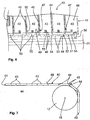
- the mat member 40 In order to reduce the risk of dislocation during transport within the elevator, or to achieve higher transport speeds, it is conceivable to carry out the mat member 40 with a plurality of rigid mat members 43, which in FIG. 6 and FIG. 7 is shown.
- the mat members 43 are arranged adjacent to each other such that during the deflection of the direction of movement of the mat member 40 each Mat member 43 to the adjacent mat member 43 is relatively movable.
- the mat members 43 are formed of metal, in the present embodiment of aluminum.
- Each mat member 43 has a hollow profile, wherein starting from the standing surface 48 of each mat member 43 to the adjacent mat member 43 each have a side wall 44 connects.
- the side walls 44 are arranged substantially parallel to each other. In addition, each side wall 44 is aligned substantially perpendicular to the base 48 of the mat member 43.
- the mat member 43 is formed as a U-profile, wherein between the side wall 44 and the base 48, the mat member 43 has a rounding 45.
- FIG. 7 It is shown that during the deflection in the region of the second deflection roller 12, the distance between two adjacent mat members 43 in the region of the rounding 45 increases.
- each mat element 40 has two edge regions 49, which are aligned parallel to one another in relation to the direction of movement of the mat element 40, wherein the belt elements 21-24 are fastened to the edge regions 49, as will be discussed below.
- the attachment points are located simultaneously in the region of the side regions 41, 42 of the mat element 40.
- the mat element 40 has at each of its two edge regions 49 a stabilizing means 50, which favors a horizontal extension of the standing surface 48 in the lifting zone 4.
- a stabilizing means 50 within the hollow profile of the mat member 43 and is thus adapted to the shape of the hollow profile.
- One of the two side walls 44 of the respective mat member 43 has a recess 47, through which the stabilizing means 50 extends at least partially and abuts the adjacent mat member 43 on the side wall 44.
- each mat member 40 on a bending means 51 whereby the bending ability of the mat member 40 is favored.
- the stabilizing means 50 and the bending means 51 are provided at the edge region 49 of the mat member 40.
- the bending means 51 has according to FIG.
- each mat member 53 has two adjacently arranged fastening means 46. At the same time, the stiffness of the mat element 40 can be adjusted via the fastening means 46.
- the rib structure 52 of the bending means 51 favors the bending ability of the mat element 40.
- the edge region 49 of the mat element 40 is fastened via a fastening element 56 with all the belt elements 21 to 24.
- the belt element 21 is fastened to the edge region 49 of the mat element 40 via the fastening element 56.
- the fastener 56 connects the stabilizer 50 to the associated belt member 21.
- the bearing member 55 is recessed within the clearance 54 of the rib structure 52 so that no collision with other objects within the elevator can occur.
- damping elements 60 it is conceivable in addition to the in FIG. 2 and FIG. 3 insert shown damping elements 60.
Landscapes
- Engineering & Computer Science (AREA)
- Mechanical Engineering (AREA)
- Delivering By Means Of Belts And Rollers (AREA)
Claims (11)
- Dispositif de transport en hauteur de piles (1), notamment de sacs, de produits semi-finis en sacs, de sections tubulaires ou de sacs reposant à plat comprenant les caractéristiques suivantes :un dispositif de transport (20) comportant plusieurs éléments de courroie (21, 22, 23, 24) rotatifs au niveau desquels au moins un élément de tapis (40) flexible est disposé ;un plan d'amenée (2) pour amener les piles (1) à l'élément de tapis (40) ;un plan de sortie (3), pour évacuer les piles (1) de l'élément de tapis (40) ;un entraînement (10) comportant une pluralité d'éléments de transmission (11, 12, 13, 14, 15, 16, 17) placés en liaison active avec les éléments de courroie (21, 22, 23, 24) pour amener l'élément de tapis (40) du plan d'amenée (2) dans le plan de sortie (3) et inversement, les éléments de transmission (11, 12, 13, 14, 15, 16, 17) étant disposés de façon à former une zone de levée (4) et une zone de transport (5) ;la zone de levée (4) repose entre le plan d'amenée (2) et le plan de sortie (3), l'élément de tapis (40) offrant une surface d'appui (48) pour la pile (1) dans la zone de levée (4) pour l'essentiel perpendiculaire à la direction de déplacement de l'élément de tapis (40) ; etla surface d'appui (48) de l'élément de tapis (40) étant parallèle à la direction de déplacement de l'élément de tapis (40) dans la zone de transport (5) ;l'entraînement (10) comportant une paire de rouleaux de déviation inférieure (13, 14) dans le plan d'amenée (2) et une paire de rouleaux de déviation supérieure (11, 12) dans le plan de sortie (3) ;caractérisé en ce que :l'entraînement (10) comporte dans le plan de sortie (3) au moins un rouleau de transfert (17) raccordé, dans la direction de déplacement de l'élément de tapis (40), à la paire de rouleaux de déviation supérieure (11, 12) ; le diamètre de la paire de rouleaux de déviation supérieure (11, 12) étant sensiblement plus grand que celui du rouleau de transfert (17).
- Dispositif selon la revendication 1, caractérisé en ce que la paire de rouleaux de déviation supérieure (11, 12) comporte un premier (11) et un deuxième rouleau de déviation (12), le diamètre des rouleaux de déviation (11, 12) dépassant de plus de 20 % approximativement le diamètre du rouleau de transfert (17), dépassant notamment d'approximativement 50 % le diamètre du rouleau de transfert (17), de façon particulièrement préférée de plus de 100 % approximativement le diamètre du rouleau de transfert (17).
- Dispositif selon la revendication 1 ou 2, caractérisé en ce que le premier (11) et le deuxième rouleau de déviation (12) de la paire de rouleaux supérieure (11, 12) ainsi que le rouleau de transfert (17) y étant raccordé comportent respectivement un axe (18, 19) autour duquel le premier (11), le deuxième rouleau de déviation (12) ainsi que le rouleau de transfert (17) sont disposés de façon à pouvoir tourner, les axes (18) des rouleaux de déviation (11, 12) reposant sur un plan horizontal commun, l'axe (19) du rouleau de transfert (17) reposant au-dessus du plan horizontal, de façon à donner un plan de sortie (3) horizontal.
- Dispositif selon l'une quelconque des revendications précédentes, caractérisé en ce que la paire de rouleaux de déviation inférieure (13, 14) comporte un premier (13) et un deuxième rouleau de déviation (14), le diamètre des rouleaux de déviation (11, 12) de la paire de rouleaux de déviation supérieure (11, 12) et de la paire de rouleaux de déviation inférieure (13, 14) étant notamment de taille identique.
- Dispositif selon l'une quelconque des revendications précédentes, caractérisé en ce que l'élément de tapis (40) comporte deux zones latérales (41, 42), deux éléments de courroie (21, 22, 23, 24) étant fixés à chaque zone latérale (41, 42), de sorte qu'un élément de courroie avant (21) et un élément de courroie arrière (22) sont fixés à la première zone latérale (41) et qu'un élément de courroie avant (23) et un élément de courroie arrière (24) sont fixés à la deuxième zone latérale (42), les éléments de courroie (21, 22, 23, 24) étant espacés les uns des autres dans chaque zone latérale (41, 42).
- Dispositif selon la revendication 5, caractérisé en ce que l'élément de courroie avant (21) et l'élément de courroie arrière (22) de la première zone latérale (41) sont réalisés de même longueur et que l'élément de courroie avant (23) et l'élément de courroie arrière (24) de la deuxième zone latérale (42) sont réalisés de même longueur.
- Dispositif selon l'une quelconque des revendications précédentes, caractérisé en ce qu'un premier rouleau de déviation (13) de la paire de rouleaux de déviation inférieure (13, 14) sert pour la déviation de l'élément de courroie avant (21) et de l'élément de courroie arrière (22) de la première zone latérale (41) et qu'un deuxième rouleau de déviation (14) de la paire de rouleaux de déviation inférieure (13, 14) sert pour la déviation de l'élément de courroie avant (23) et de l'élément de courroie arrière (24) de la deuxième zone latérale (42).
- Dispositif selon l'une quelconque des revendications précédentes, caractérisé en ce qu'un premier rouleau de déviation (11) de la paire de rouleaux de déviation supérieure (11, 12) sert pour la déviation de l'élément de courroie avant (21) et de l'élément de courroie arrière (22) de la première zone latérale (41) et qu'un deuxième rouleau de déviation (12) de la paire de rouleaux de déviation supérieure (11, 12) sert pour la déviation de l'élément de courroie avant (23) et de l'élément de courroie arrière (24) de la deuxième zone latérale (42), l'élément de courroie avant (21) et l'élément de courroie arrière (22) de la première zone latérale (41) reposant simultanément contre le deuxième rouleau de déviation (12) de la paire de rouleaux de déviation supérieure (11, 12).
- Dispositif selon l'une quelconque des revendications précédentes, caractérisé en ce que l'entraînement (10) comporte des rouleaux auxiliaires (15, 16) servant d'éléments de transmission et auxquels tous les éléments de courroie (21, 22, 23, 24) sont articulés, les rouleaux auxiliaires (15, 16) étant notamment disposés entre le rouleau de transfert (17) et le premier rouleau de déviation (11) de la paire de rouleaux inférieure (11, 12).
- Dispositif selon l'une quelconque des revendications précédentes, caractérisé en ce qu'un élément d'amortissement (60) est disposé dans le plan d'amenée (2) et/ou dans le plan de sortie (3), notamment que l'élément d'amortissement (60) est disposé au niveau du châssis (80) du dispositif.
- Dispositif selon l'une quelconque des revendications précédentes, caractérisé en ce que l'élément de tapis (40) est réalisé à partir d'une pluralité de maillons de tapis (43) rigides disposés de telle sorte à proximité les uns des autres qu'en cas de déviation de la direction de déplacement de l'élément de tapis (40) au niveau des rouleaux de déviation (11, 12, 13, 14) ainsi que des rouleaux auxiliaires (15, 16) et du rouleau de transfert (17), chaque maillon de tapis (43) a une mobilité relative par rapport au maillon de tapis (43) connexe.
Applications Claiming Priority (2)
| Application Number | Priority Date | Filing Date | Title |
|---|---|---|---|
| DE102013101143 | 2013-02-05 | ||
| DE102013104563.4A DE102013104563B4 (de) | 2013-02-05 | 2013-05-03 | Vorrichtung zum Höhentransport von Stapeln mit einer Übergaberolle |
Publications (2)
| Publication Number | Publication Date |
|---|---|
| EP2762425A1 EP2762425A1 (fr) | 2014-08-06 |
| EP2762425B1 true EP2762425B1 (fr) | 2016-07-13 |
Family
ID=50031270
Family Applications (1)
| Application Number | Title | Priority Date | Filing Date |
|---|---|---|---|
| EP14154025.2A Active EP2762425B1 (fr) | 2013-02-05 | 2014-02-05 | Dispositif avec galet de transfert pour soulever des produits empilés |
Country Status (2)
| Country | Link |
|---|---|
| EP (1) | EP2762425B1 (fr) |
| DE (1) | DE102013104563B4 (fr) |
Family Cites Families (11)
| Publication number | Priority date | Publication date | Assignee | Title |
|---|---|---|---|---|
| FR589257A (fr) * | 1924-06-24 | 1925-05-26 | Soc D Const Et D Installations | Appareil transporteur élévateur pour colis de formes diverses |
| US2828002A (en) * | 1955-11-09 | 1958-03-25 | Hewlett M Sawrie | Sling conveyor |
| GB797738A (en) * | 1956-01-06 | 1958-07-09 | Post Office | Improvements in or relating to endless band conveyors |
| GB1038955A (en) | 1963-11-14 | 1966-08-17 | Bagshawe & Co Ltd | Improvements in or relating to conveyors |
| US3268061A (en) | 1965-10-20 | 1966-08-23 | Rapids Standard Co Inc | Continuous and reversible vertical conveyor |
| US3481449A (en) | 1967-11-13 | 1969-12-02 | John M Leach | Conveying systems |
| JPS58152702A (ja) * | 1982-03-04 | 1983-09-10 | Tamai Tekko:Kk | バ−チカル・コンベヤ |
| US4627530A (en) | 1983-10-20 | 1986-12-09 | Universal Conveyor Co., Inc. | Elevating chain conveyor |
| DE3833750A1 (de) | 1988-09-30 | 1990-04-05 | Nerak Foerdertechnik | Vertikal-stueckgutfoerderer |
| FR2756814B1 (fr) | 1996-12-10 | 1999-02-26 | Armoricaine De Manutention Aut | Transporteur a marches souples du type "c" |
| DE10117665A1 (de) * | 2001-04-09 | 2002-10-17 | Knapp Logistik Automation | Vertikalförderer in Form eines Umlauf-C-Förderers zum Vertikalfördern von stückgutartigen Fördergütern |
-
2013
- 2013-05-03 DE DE102013104563.4A patent/DE102013104563B4/de not_active Expired - Fee Related
-
2014
- 2014-02-05 EP EP14154025.2A patent/EP2762425B1/fr active Active
Also Published As
| Publication number | Publication date |
|---|---|
| DE102013104563B4 (de) | 2017-02-16 |
| EP2762425A1 (fr) | 2014-08-06 |
| DE102013104563A1 (de) | 2014-08-07 |
Similar Documents
| Publication | Publication Date | Title |
|---|---|---|
| EP2794433B1 (fr) | Installation de préparation des commandes et procédé de préparation des marchandises commandées | |
| EP3248914B1 (fr) | Glissière pour marchandise de détail et procédé d'utilisation d'une telle glissière | |
| EP2332865B9 (fr) | Dispositif de palettisation et/ou de dépalettisation | |
| DE4100769C2 (de) | Vorrichtung zum Fördern von Produkten in einer Verpackungsmaschine | |
| EP2444341B1 (fr) | Dispositif de traitement de produits en vrac d'une unité de transport, notamment d'un conteneur interchangeable et dispositif de déchargement | |
| EP3652096B1 (fr) | Dispositif de stockage et de convoyeur et procédé de fonctionnement du dispositif de stockage et de convoyeur | |
| EP2412650B1 (fr) | Dispositif de stockage pour récipients et procédé de stockage de récipients | |
| DE29701564U1 (de) | Pickerstraße mit entgegengesetztem Traytransport | |
| DE60112697T2 (de) | Vorrichtung zum Empfangen und Ausstossen von flächigen Gegenständen in einer Maschine zu ihrer Bearbeitung | |
| DE102015113021A1 (de) | Gruppieren von Gütern | |
| EP1428758B1 (fr) | Dispositif pour trier et transporter des matériaux en vrac | |
| DE102020116880A1 (de) | Verfahren und Vorrichtung zum Entladen eines Packstücke aufweisenden Behälters | |
| WO2013000527A1 (fr) | Dispositif et procédé permettant de grouper des objets | |
| EP4601976A1 (fr) | Dispositif de transport et de séparation de pièces | |
| WO2018114135A1 (fr) | Système de transport sûr | |
| DE2945213C2 (de) | Förderbahn mit Eingabe- und Abwerfvorrichtungen | |
| EP3106412B1 (fr) | Groupement de marchandises | |
| DE102013104563B4 (de) | Vorrichtung zum Höhentransport von Stapeln mit einer Übergaberolle | |
| AT402728B (de) | Vakuum-eingabegerät | |
| DE19821108C2 (de) | Gruppierungsvorrichtung für Packungen | |
| DE60318739T2 (de) | Verfahren und vorrichtung zur handhabung von walzen | |
| EP1676491A1 (fr) | Dispositif pour remplir d'un dispositif subordonné | |
| EP2762424A1 (fr) | Dispositif pour soulever des éléments empilés comprenant un élément de tapis | |
| DE102013101140B4 (de) | Vorrichtung zum Höhentransport von Stapeln mit einem Dämpfungselement | |
| AT517875B1 (de) | Kommissioniervorrichtung und Kommissionierlager |
Legal Events
| Date | Code | Title | Description |
|---|---|---|---|
| PUAI | Public reference made under article 153(3) epc to a published international application that has entered the european phase |
Free format text: ORIGINAL CODE: 0009012 |
|
| 17P | Request for examination filed |
Effective date: 20140205 |
|
| AK | Designated contracting states |
Kind code of ref document: A1 Designated state(s): AL AT BE BG CH CY CZ DE DK EE ES FI FR GB GR HR HU IE IS IT LI LT LU LV MC MK MT NL NO PL PT RO RS SE SI SK SM TR |
|
| AX | Request for extension of the european patent |
Extension state: BA ME |
|
| R17P | Request for examination filed (corrected) |
Effective date: 20150206 |
|
| RBV | Designated contracting states (corrected) |
Designated state(s): AL AT BE BG CH CY CZ DE DK EE ES FI FR GB GR HR HU IE IS IT LI LT LU LV MC MK MT NL NO PL PT RO RS SE SI SK SM TR |
|
| GRAP | Despatch of communication of intention to grant a patent |
Free format text: ORIGINAL CODE: EPIDOSNIGR1 |
|
| INTG | Intention to grant announced |
Effective date: 20160210 |
|
| GRAP | Despatch of communication of intention to grant a patent |
Free format text: ORIGINAL CODE: EPIDOSNIGR1 |
|
| INTG | Intention to grant announced |
Effective date: 20160506 |
|
| GRAS | Grant fee paid |
Free format text: ORIGINAL CODE: EPIDOSNIGR3 |
|
| GRAA | (expected) grant |
Free format text: ORIGINAL CODE: 0009210 |
|
| AK | Designated contracting states |
Kind code of ref document: B1 Designated state(s): AL AT BE BG CH CY CZ DE DK EE ES FI FR GB GR HR HU IE IS IT LI LT LU LV MC MK MT NL NO PL PT RO RS SE SI SK SM TR |
|
| REG | Reference to a national code |
Ref country code: GB Ref legal event code: FG4D Free format text: NOT ENGLISH |
|
| REG | Reference to a national code |
Ref country code: AT Ref legal event code: REF Ref document number: 812111 Country of ref document: AT Kind code of ref document: T Effective date: 20160715 Ref country code: CH Ref legal event code: EP |
|
| REG | Reference to a national code |
Ref country code: IE Ref legal event code: FG4D Free format text: LANGUAGE OF EP DOCUMENT: GERMAN |
|
| REG | Reference to a national code |
Ref country code: DE Ref legal event code: R096 Ref document number: 502014001071 Country of ref document: DE |
|
| REG | Reference to a national code |
Ref country code: LT Ref legal event code: MG4D |
|
| REG | Reference to a national code |
Ref country code: NL Ref legal event code: MP Effective date: 20160713 |
|
| PG25 | Lapsed in a contracting state [announced via postgrant information from national office to epo] |
Ref country code: LT Free format text: LAPSE BECAUSE OF FAILURE TO SUBMIT A TRANSLATION OF THE DESCRIPTION OR TO PAY THE FEE WITHIN THE PRESCRIBED TIME-LIMIT Effective date: 20160713 Ref country code: FI Free format text: LAPSE BECAUSE OF FAILURE TO SUBMIT A TRANSLATION OF THE DESCRIPTION OR TO PAY THE FEE WITHIN THE PRESCRIBED TIME-LIMIT Effective date: 20160713 Ref country code: HR Free format text: LAPSE BECAUSE OF FAILURE TO SUBMIT A TRANSLATION OF THE DESCRIPTION OR TO PAY THE FEE WITHIN THE PRESCRIBED TIME-LIMIT Effective date: 20160713 Ref country code: RS Free format text: LAPSE BECAUSE OF FAILURE TO SUBMIT A TRANSLATION OF THE DESCRIPTION OR TO PAY THE FEE WITHIN THE PRESCRIBED TIME-LIMIT Effective date: 20160713 Ref country code: IS Free format text: LAPSE BECAUSE OF FAILURE TO SUBMIT A TRANSLATION OF THE DESCRIPTION OR TO PAY THE FEE WITHIN THE PRESCRIBED TIME-LIMIT Effective date: 20161113 Ref country code: NO Free format text: LAPSE BECAUSE OF FAILURE TO SUBMIT A TRANSLATION OF THE DESCRIPTION OR TO PAY THE FEE WITHIN THE PRESCRIBED TIME-LIMIT Effective date: 20161013 Ref country code: NL Free format text: LAPSE BECAUSE OF FAILURE TO SUBMIT A TRANSLATION OF THE DESCRIPTION OR TO PAY THE FEE WITHIN THE PRESCRIBED TIME-LIMIT Effective date: 20160713 |
|
| PG25 | Lapsed in a contracting state [announced via postgrant information from national office to epo] |
Ref country code: ES Free format text: LAPSE BECAUSE OF FAILURE TO SUBMIT A TRANSLATION OF THE DESCRIPTION OR TO PAY THE FEE WITHIN THE PRESCRIBED TIME-LIMIT Effective date: 20160713 Ref country code: PT Free format text: LAPSE BECAUSE OF FAILURE TO SUBMIT A TRANSLATION OF THE DESCRIPTION OR TO PAY THE FEE WITHIN THE PRESCRIBED TIME-LIMIT Effective date: 20161114 Ref country code: SE Free format text: LAPSE BECAUSE OF FAILURE TO SUBMIT A TRANSLATION OF THE DESCRIPTION OR TO PAY THE FEE WITHIN THE PRESCRIBED TIME-LIMIT Effective date: 20160713 Ref country code: GR Free format text: LAPSE BECAUSE OF FAILURE TO SUBMIT A TRANSLATION OF THE DESCRIPTION OR TO PAY THE FEE WITHIN THE PRESCRIBED TIME-LIMIT Effective date: 20161014 Ref country code: LV Free format text: LAPSE BECAUSE OF FAILURE TO SUBMIT A TRANSLATION OF THE DESCRIPTION OR TO PAY THE FEE WITHIN THE PRESCRIBED TIME-LIMIT Effective date: 20160713 Ref country code: PL Free format text: LAPSE BECAUSE OF FAILURE TO SUBMIT A TRANSLATION OF THE DESCRIPTION OR TO PAY THE FEE WITHIN THE PRESCRIBED TIME-LIMIT Effective date: 20160713 |
|
| REG | Reference to a national code |
Ref country code: DE Ref legal event code: R097 Ref document number: 502014001071 Country of ref document: DE |
|
| PG25 | Lapsed in a contracting state [announced via postgrant information from national office to epo] |
Ref country code: EE Free format text: LAPSE BECAUSE OF FAILURE TO SUBMIT A TRANSLATION OF THE DESCRIPTION OR TO PAY THE FEE WITHIN THE PRESCRIBED TIME-LIMIT Effective date: 20160713 Ref country code: RO Free format text: LAPSE BECAUSE OF FAILURE TO SUBMIT A TRANSLATION OF THE DESCRIPTION OR TO PAY THE FEE WITHIN THE PRESCRIBED TIME-LIMIT Effective date: 20160713 |
|
| PLBE | No opposition filed within time limit |
Free format text: ORIGINAL CODE: 0009261 |
|
| STAA | Information on the status of an ep patent application or granted ep patent |
Free format text: STATUS: NO OPPOSITION FILED WITHIN TIME LIMIT |
|
| PG25 | Lapsed in a contracting state [announced via postgrant information from national office to epo] |
Ref country code: BG Free format text: LAPSE BECAUSE OF FAILURE TO SUBMIT A TRANSLATION OF THE DESCRIPTION OR TO PAY THE FEE WITHIN THE PRESCRIBED TIME-LIMIT Effective date: 20161013 Ref country code: SM Free format text: LAPSE BECAUSE OF FAILURE TO SUBMIT A TRANSLATION OF THE DESCRIPTION OR TO PAY THE FEE WITHIN THE PRESCRIBED TIME-LIMIT Effective date: 20160713 Ref country code: SK Free format text: LAPSE BECAUSE OF FAILURE TO SUBMIT A TRANSLATION OF THE DESCRIPTION OR TO PAY THE FEE WITHIN THE PRESCRIBED TIME-LIMIT Effective date: 20160713 Ref country code: BE Free format text: LAPSE BECAUSE OF NON-PAYMENT OF DUE FEES Effective date: 20170228 Ref country code: DK Free format text: LAPSE BECAUSE OF FAILURE TO SUBMIT A TRANSLATION OF THE DESCRIPTION OR TO PAY THE FEE WITHIN THE PRESCRIBED TIME-LIMIT Effective date: 20160713 |
|
| 26N | No opposition filed |
Effective date: 20170418 |
|
| PG25 | Lapsed in a contracting state [announced via postgrant information from national office to epo] |
Ref country code: SI Free format text: LAPSE BECAUSE OF FAILURE TO SUBMIT A TRANSLATION OF THE DESCRIPTION OR TO PAY THE FEE WITHIN THE PRESCRIBED TIME-LIMIT Effective date: 20160713 |
|
| PG25 | Lapsed in a contracting state [announced via postgrant information from national office to epo] |
Ref country code: MC Free format text: LAPSE BECAUSE OF FAILURE TO SUBMIT A TRANSLATION OF THE DESCRIPTION OR TO PAY THE FEE WITHIN THE PRESCRIBED TIME-LIMIT Effective date: 20160713 |
|
| REG | Reference to a national code |
Ref country code: CH Ref legal event code: PL |
|
| PG25 | Lapsed in a contracting state [announced via postgrant information from national office to epo] |
Ref country code: CH Free format text: LAPSE BECAUSE OF NON-PAYMENT OF DUE FEES Effective date: 20170228 Ref country code: LI Free format text: LAPSE BECAUSE OF NON-PAYMENT OF DUE FEES Effective date: 20170228 |
|
| REG | Reference to a national code |
Ref country code: IE Ref legal event code: MM4A |
|
| REG | Reference to a national code |
Ref country code: FR Ref legal event code: ST Effective date: 20171031 |
|
| PG25 | Lapsed in a contracting state [announced via postgrant information from national office to epo] |
Ref country code: LU Free format text: LAPSE BECAUSE OF NON-PAYMENT OF DUE FEES Effective date: 20170205 |
|
| PG25 | Lapsed in a contracting state [announced via postgrant information from national office to epo] |
Ref country code: FR Free format text: LAPSE BECAUSE OF NON-PAYMENT OF DUE FEES Effective date: 20170228 |
|
| REG | Reference to a national code |
Ref country code: BE Ref legal event code: MM Effective date: 20170228 |
|
| PG25 | Lapsed in a contracting state [announced via postgrant information from national office to epo] |
Ref country code: IE Free format text: LAPSE BECAUSE OF NON-PAYMENT OF DUE FEES Effective date: 20170205 |
|
| PG25 | Lapsed in a contracting state [announced via postgrant information from national office to epo] |
Ref country code: MT Free format text: LAPSE BECAUSE OF FAILURE TO SUBMIT A TRANSLATION OF THE DESCRIPTION OR TO PAY THE FEE WITHIN THE PRESCRIBED TIME-LIMIT Effective date: 20160713 |
|
| GBPC | Gb: european patent ceased through non-payment of renewal fee |
Effective date: 20180205 |
|
| PG25 | Lapsed in a contracting state [announced via postgrant information from national office to epo] |
Ref country code: AL Free format text: LAPSE BECAUSE OF FAILURE TO SUBMIT A TRANSLATION OF THE DESCRIPTION OR TO PAY THE FEE WITHIN THE PRESCRIBED TIME-LIMIT Effective date: 20160713 |
|
| PG25 | Lapsed in a contracting state [announced via postgrant information from national office to epo] |
Ref country code: GB Free format text: LAPSE BECAUSE OF NON-PAYMENT OF DUE FEES Effective date: 20180205 |
|
| PG25 | Lapsed in a contracting state [announced via postgrant information from national office to epo] |
Ref country code: HU Free format text: LAPSE BECAUSE OF FAILURE TO SUBMIT A TRANSLATION OF THE DESCRIPTION OR TO PAY THE FEE WITHIN THE PRESCRIBED TIME-LIMIT; INVALID AB INITIO Effective date: 20140205 |
|
| PG25 | Lapsed in a contracting state [announced via postgrant information from national office to epo] |
Ref country code: CY Free format text: LAPSE BECAUSE OF NON-PAYMENT OF DUE FEES Effective date: 20160713 |
|
| PG25 | Lapsed in a contracting state [announced via postgrant information from national office to epo] |
Ref country code: MK Free format text: LAPSE BECAUSE OF FAILURE TO SUBMIT A TRANSLATION OF THE DESCRIPTION OR TO PAY THE FEE WITHIN THE PRESCRIBED TIME-LIMIT Effective date: 20160713 |
|
| PG25 | Lapsed in a contracting state [announced via postgrant information from national office to epo] |
Ref country code: TR Free format text: LAPSE BECAUSE OF FAILURE TO SUBMIT A TRANSLATION OF THE DESCRIPTION OR TO PAY THE FEE WITHIN THE PRESCRIBED TIME-LIMIT Effective date: 20160713 |
|
| REG | Reference to a national code |
Ref country code: AT Ref legal event code: MM01 Ref document number: 812111 Country of ref document: AT Kind code of ref document: T Effective date: 20190205 |
|
| PG25 | Lapsed in a contracting state [announced via postgrant information from national office to epo] |
Ref country code: AT Free format text: LAPSE BECAUSE OF NON-PAYMENT OF DUE FEES Effective date: 20190205 |
|
| PGFP | Annual fee paid to national office [announced via postgrant information from national office to epo] |
Ref country code: DE Payment date: 20260228 Year of fee payment: 13 |
|
| PGFP | Annual fee paid to national office [announced via postgrant information from national office to epo] |
Ref country code: IT Payment date: 20260220 Year of fee payment: 13 |
|
| PGFP | Annual fee paid to national office [announced via postgrant information from national office to epo] |
Ref country code: CZ Payment date: 20260126 Year of fee payment: 13 |