EP2761983B1 - Verlängerbare förderanordnung mit einer dichtung - Google Patents
Verlängerbare förderanordnung mit einer dichtung Download PDFInfo
- Publication number
- EP2761983B1 EP2761983B1 EP14152104.7A EP14152104A EP2761983B1 EP 2761983 B1 EP2761983 B1 EP 2761983B1 EP 14152104 A EP14152104 A EP 14152104A EP 2761983 B1 EP2761983 B1 EP 2761983B1
- Authority
- EP
- European Patent Office
- Prior art keywords
- frame
- conveyor
- flexible seal
- guide element
- conveyor assembly
- Prior art date
- Legal status (The legal status is an assumption and is not a legal conclusion. Google has not performed a legal analysis and makes no representation as to the accuracy of the status listed.)
- Active
Links
Images


Classifications
-
- B—PERFORMING OPERATIONS; TRANSPORTING
- B65—CONVEYING; PACKING; STORING; HANDLING THIN OR FILAMENTARY MATERIAL
- B65G—TRANSPORT OR STORAGE DEVICES, e.g. CONVEYORS FOR LOADING OR TIPPING, SHOP CONVEYOR SYSTEMS OR PNEUMATIC TUBE CONVEYORS
- B65G15/00—Conveyors having endless load-conveying surfaces, i.e. belts and like continuous members, to which tractive effort is transmitted by means other than endless driving elements of similar configuration
- B65G15/22—Conveyors having endless load-conveying surfaces, i.e. belts and like continuous members, to which tractive effort is transmitted by means other than endless driving elements of similar configuration comprising a series of co-operating units
- B65G15/26—Conveyors having endless load-conveying surfaces, i.e. belts and like continuous members, to which tractive effort is transmitted by means other than endless driving elements of similar configuration comprising a series of co-operating units extensible, e.g. telescopic
-
- A—HUMAN NECESSITIES
- A01—AGRICULTURE; FORESTRY; ANIMAL HUSBANDRY; HUNTING; TRAPPING; FISHING
- A01D—HARVESTING; MOWING
- A01D41/00—Combines, i.e. harvesters or mowers combined with threshing devices
- A01D41/12—Details of combines
- A01D41/1208—Tanks for grain or chaff
- A01D41/1217—Unloading mechanisms
-
- A—HUMAN NECESSITIES
- A01—AGRICULTURE; FORESTRY; ANIMAL HUSBANDRY; HUNTING; TRAPPING; FISHING
- A01D—HARVESTING; MOWING
- A01D61/00—Elevators or conveyors for binders or combines
- A01D61/02—Endless belts
-
- B—PERFORMING OPERATIONS; TRANSPORTING
- B65—CONVEYING; PACKING; STORING; HANDLING THIN OR FILAMENTARY MATERIAL
- B65G—TRANSPORT OR STORAGE DEVICES, e.g. CONVEYORS FOR LOADING OR TIPPING, SHOP CONVEYOR SYSTEMS OR PNEUMATIC TUBE CONVEYORS
- B65G21/00—Supporting or protective framework or housings for endless load-carriers or traction elements of belt or chain conveyors
- B65G21/10—Supporting or protective framework or housings for endless load-carriers or traction elements of belt or chain conveyors movable, or having interchangeable or relatively movable parts; Devices for moving framework or parts thereof
- B65G21/14—Supporting or protective framework or housings for endless load-carriers or traction elements of belt or chain conveyors movable, or having interchangeable or relatively movable parts; Devices for moving framework or parts thereof to allow adjustment of length or configuration of load-carrier or traction element
Definitions
- the present invention pertains to an extendable conveyor assembly provided with a seal.
- Combines are used in agricultural operations to harvest, thresh and separate and finally clean crops grown on a field in order to obtain cleaned grain.
- the grain is stored in a grain tank and unloaded into a container of a transport vehicle for further processing.
- auger conveyors While in the past, mainly auger conveyors have been used, it has been proposed recently to use a belt conveyor for unloading the grain from a combine grain tank.
- the lower frame is slidably mounted with respect to the upper frame in order to extend and retract the conveyor for unloading respectively transport.
- Both frames comprise aluminum extrusion profiles and support belt rollers, around which a single belt or two separate belts are running.
- a cover enclosing the lateral faces of the conveyors and the top of the upper frame is connected to the lower frame.
- a skirt is mounted to the profile of the lower frame, ending adjacent the upper run of
- a conveyor assembly comprises a first frame supporting a first conveyor for feeding material in a first conveying direction.
- the conveyor also comprises a second frame supporting a second conveyor for feeding material in a second conveying direction parallel to the first conveying direction.
- the second frame is movable with respect to the first frame along the second conveying direction between a retracted position and an extended position.
- a side shield is connected to a side of the second frame and shields the second conveyor laterally.
- An elongate, flexible seal is mounted to the side shield, the seal bridging a gap between the side shield and the second frame. The seal thus prevents conveyed material from falling off the second conveyor and being lost.
- the seal comprises a proximal part in a first position spaced from the second frame and a distal part in a second position abutting the second frame, wherein the proximal part of the seal extends over a part of a length of the second frame projecting beyond the first frame.
- the respective parts of the seal are preferably arranged to move under control of a guide element mounted in the vicinity of a distal end of the first frame from the first position to the second position as the second frame is moving from the retracted position into the extended position. This movement is reversed, i.e. the guide element moves the seal from the second position into the first position when the second frame moves from the extended into the retracted position.
- the guide element can have a first guide surface adjacent the seal.
- the first guide surface is oriented at the proximal end of the guide element essentially vertical and at the distal end of the guide element inwards and downwards and turns between the proximal and distal end successively from the essentially vertical orientation to the inwards and downwards orientation to move the seal from the first position to the second position when the second frame is moved from the retracted to the extended position.
- the inwards and downwards orientation corresponds essentially to the orientation of the second frame onto which the seal is to be laid or is a certain degree steeper.
- the seal has an end with two lips that enclose, when in the second position, a nose of a profile element of the second frame.
- the first guide surface preferably engages an inner surface of an upper lip.
- the guide element further preferably has a second guide surface adjacent the seal, the second guide surface oriented at the proximal end of the guide element essentially vertical and at the distal end of the guide element downwards and inwards towards the second conveyor and turning between the proximal and distal end successively from the essentially vertical orientation to the downwards and inwards orientation to move a lower lip of the seal from the a vertical position to a position abutting an outer face of the nose of the profile element of the second frame when the second frame is moved from the retracted to the extended position.
- the guide element can be outwardly cranked in the vicinity of its proximal end.
- the first frame comprises two first profile elements supporting the first conveyor.
- the first profile elements each comprise a vertical wall extending beneath the first conveyor.
- a projecting element projects inwards from the lower end of the vertical wall.
- the projecting element is enclosed by a corresponding cavity of a second profile element of the second frame and the guide element is mounted on the vertical wall.
- the conveyor assembly according to the present invention can be used for any purpose. It is in particular suited for an agricultural harvesting machine like a combine for unloading grain from a grain tank or for a forage harvester for conveying chopped crop to a transport vehicle.
- An agricultural combine 10 shown in Figure 1 comprises a frame 12 supported on driven front wheels 14 and steerable rear wheels 16. Crop harvested from a field by a header (not shown) is fed through a feeder house 18 into threshing, separating and cleaning assemblies (not shown) within the frame 12 and finally cleaned grain is deposited in a grain tank 22 by a clean grain elevator 20. Operation of the combine 10 is controlled from an operator's cab 24. A conveyor assembly 26 is provided for unloading the clean grain from the grain tank 22 into a container of a transport vehicle (not shown).
- the conveyor assembly 26 comprises a first conveyor 28 and a second conveyor 30.
- Each of first conveyor 28 and second conveyor 30 is a belt conveyor having a belt and a plurality of rollers about which the belt is entrained.
- a belt 40 (a single belt) is entrained around all the rollers that comprise both the first conveyor 28 and the second conveyor 30.
- the belt 40 recirculates about a roller 32 (which is proximal) and a roller 34 (which is distal) of the first conveyor 28 and recirculates around a roller 36 (which is proximal) and a roller 38 (which is distal) of the second conveyor 30.
- the belt 40 also recirculates about a roller 42, a roller 44, and a roller 46.
- the roller 42, the roller 44, and the roller 46 serve to tension the belt 40. Further, due to this roller and belt arrangement they permit the second conveyor 30 to be extended from the retracted position (shown) to an extended position (not shown). In this extended position, the roller 36 and the roller 38 are moved towards the right hand side with respect to Figure 1 together with the two lateral profile elements that support each end of the roller 36 and the roller 38.
- the upper run of the belt 40 that extends between roller 32 and roller 34 of the first conveyor 28 is driven by an assigned motor (electrical or hydraulic, not shown) or a mechanical drive train from an engine of the combine 10, to move outwards, in Figure 1 towards the right hand side.
- the upper run of the belt 40 that extends between the roller 36 and the roller 38 of the second conveyor 30 is driven in the same direction as the upper run of the belt 40 that extends between the roller 32 and the roller 34.
- the upper run of the belt 40 that extends between the roller 36 and the roller 38 receives the material fed by the first conveyor 28 to the second conveyor 30 at the distal discharge point of the first conveyor 28 (i.e. at roller 34).
- the upper runs of the belt 40 continuously move from a proximal position that is adjacent to the agricultural harvesting machine 10 to a distal position that is away from the agricultural harvesting machine 10, where the grain is unloaded from the conveyor assembly 26.
- the second conveyor 30 can be extended and retracted in a direction parallel to the conveying direction of the belt 40 and parallel to the longitudinal extent of the first conveyor 28 and the second conveyor 30.
- the conveyor assembly 26 can be moved by an actuator (not shown) to rotate at its proximal end around a vertical axis, and the inclination of the conveyor assembly 26 can be preferably controlled by another actuator (also not shown).
- the conveyor assembly 26 In the extended position (not shown), the conveyor assembly 26 is pivoted with respect to the agricultural harvesting machine 10 to extend perpendicular to the direction of harvesting travel of the agricultural harvesting machine 10. In this position, the conveyor assembly 26 in its extended position enables a grain transport vehicle to be driven alongside the agricultural harvesting machine 10.
- the grain from grain tank 22 is carried by conventional means to an inlet of the first conveyor 28 located adjacent to roller 32, where it is carried by the upper run of the first conveyor to roller 34, which defines the exit of the first conveyor 28.
- the grain then falls off the end of the first conveyor 28, and on to the upper run of belt 40 extending between roller 36 and roller 38.
- the upper run of belt 40 of the second conveyor 30 receives the grain from the first conveyor and carries the grain to an exit spout 48 at the distal end of the second conveyor 30 and the conveyor assembly 26.
- first conveyor 28 and second conveyor 30 could be provided with separate belts in place of the belt 40 (illustrated herein) that are driven independently.
- one endless belt wraps around and is driven by the rollers that comprise the first conveyor 28, i.e. the roller 32 and the roller 34, and another belt wraps around and is driven by the rollers that comprise the second conveyor 30 i.e. the roller 36 and the roller 38.
- an additional motor would typically be provided to drive the belt wrapped around the roller 36 and the roller 38.
- FIG. 2 a perspective, partial cutaway view of the first conveyor 28 and second conveyor 30 is shown.
- the roller 34 of the first conveyor 28 is supported on a first frame 50 that comprises two lateral profile elements 52, which extend over the entire length of the first conveyor 28 and are coupled with the frame 12 of the combine 10 and enclose the first conveyor 28 between them.
- the lateral profile elements 52 of the first frame 50 each comprise a central hollow, part 54 (which is central and rectangular and in the form of a wall), an upper part 57 directly connected to the top of the part 54, and a vertical wall 56 beneath the part 54, planar with the outer vertical wall of the part 54.
- the upper part 57 is also hollow and angled towards the center of the first conveyor 28.
- a projecting element 58 projects inwards toward the center of the conveyor assembly 26.
- the projecting element 58 has a rectangular cross section and is hollow.
- the lateral profile elements 52 of the first frame 50 preferably consist of extruded aluminum.
- the part of the belt 40 forming the second conveyor 30 is likewise supported on a second frame 60 comprising two lateral profile elements 62 extending over the entire length of the second conveyor 30.
- the lateral profile elements 62 support the roller 36, the roller 38, and the roller 42 around which the run of the belt 40 forming the second conveyor 30 is entrained, wherein one of the two lateral profile elements 62 is disposed at one end of these rollers to support the rollers at one end for rotation, and the other of the two lateral profile elements 62 is disposed at the other end of these rollers to support the other end of these rollers for rotation.
- Each of the lateral profile elements 62 comprises a vertical wall 64 to which the shafts of the roller 36, the roller 38, and the roller 42 are mounted.
- an extension 66 having an L-shape is formed, the outer, vertical leg of which serving to mount a shield 68 comprising a side shield 70 enclosing the sides and a top shield 72 covering the top of the conveyor assembly 26.
- the side shield is bolted to the vertical legs of extension 66.
- the lateral profile elements 62 form a cavity 74 which is surrounded by an wall 76 that is inner and vertical, a wall 78 that is disposed at a lower end of wall 76 and is oriented generally horizontally, a wall 80 that is disposed at an upper end of wall 76 and is oriented generally horizontally, and upper and lower walls 82 that are oriented to the outside of wall 76 and are coupled to the wall 78, and wall 80, in such a way as to define a gap between upper and lower walls 82.
- While 76, wall 78, wall 80, and upper and lower walls 82 are oriented with respect to each other to define the cavity 74 such that the projecting element 58 of the lateral profile elements 52 of the first conveyor 28 can be inserted (slid) into the cavity 74.
- the upper wall 82 also extends above wall 80, turns inwards and merges with a wall 84 that extends vertically and outwardly from the wall 76.
- a nose 86 of the lateral profile element 62 projects upwardly and outwardly above the junction between upper wall 82 and wall 84,
- a triangular, hollow extension 88 is provided on the interior face of the upper wall 82. It serves as a support for the belt 40.
- the lateral profile elements 62 of the second frame 60 preferably consist of extruded aluminum.
- Adjustment of the second conveyor 30 between the extended and retracted position is achieved by means of a chain 90 entrained around a sprocket 92 mounted on the vertical wall 56.
- An elongate, flexible seal 94 is mounted to the interior faces of the side shield 70. From an outer, upper mounting point on the side shield 70, the flexible seal 94 extends downwards and inwards. At their lower, inner ends, the flexible seal 94 branches into a lower lip 96 and an upper lip 98, enclosing the nose 86 of the lateral profile element 62 of the second frame 60 between them.
- the flexible seal 94 provides a sealing between the side shield 70 and the (outer, seen in the proximal/distal direction) parts of the lateral profile elements 62 that project beyond the first frame 50.
- the flexible seal 94 cannot not touch the lateral profile elements 62 of the second frame 60 that are located directly beneath first frame 50.
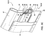
- the proximal areas of the flexible seal 94 are thus oriented essentially vertically in a first position (cf. Figure 3E ) in the vicinity of the outer face of vertical wall 56, while only the distal areas of the flexible seal 94 are in a second position to seal the gap between the side shield 70 and the lateral profile element 62 of the second frame 60.
- a guide element 100 serves to move the flexible seal 94 between its first and second position as the second conveyor 30 is extended and retracted.
- the guide element 100 is mounted at the distal end of the first conveyor 28 and is fixed to the vertical wall 56 of the lateral profile element 52 of the first frame 50. In the proximal/distal direction, the guide element 100 extends from a proximal end 102 behind the front edge of the first frame 50 to a distal end 104 in front of the front edge of the first frame 50.
- the guide element 100 has a first, inner surface 106 that is nearly vertically or vertically oriented at the proximal end 102 (i.e. the rear end) and inwards and slightly downwards oriented at the distal end 104 (i.e. the forward end), corresponding approximately to the orientation of the nose 86 of the second frame 60 onto which the upper lip 98 is to be laid.
- the first surface 106 gradually turns from the vertical orientation to the inwards and downwards orientation, as can be seen in Figure 3A to 3E .
- the first surface 106 thus extends in its distal part above and beyond the nose 86 towards the inside of the second conveyor 30. In its proximal part, the first surface 106 is located on the outward side of nose 86.
- the guide element 100 further has a second, outer surface 108 that is nearly or exactly vertically oriented at the proximal end 102 and downwards and inwards oriented at the distal end 104. Between the proximal end 102 and the distal end 104, the first surface gradually turns from the vertical orientation to the downwards and inwards orientation, as can be seen in Figure 3A to 3E , as well.
- the second surface 108 is located on the outward side of nose 86 over its entire length. In the vicinity of the rear end, the guide element 100 is angled outwardly at a position indicated as 110.
- the first surface 106 and the second surface 108 are separate from each other along their distal part and merge together in the vicinity of the angled position 110. Below the second surface 108, the guide element 100 turns into a vertical flange 112 bolted to the vertical wall 56.
- the guide element 100 is formed of steel or another suitable material.
- Figure 3A shows the flexible seal 94 in the second position in which the lower lip 96 and upper lip 98 enclose the nose 86 of the lateral profile element 62 of the second frame 60 between them, since the (distal) part of the second conveyor 30 with flexible seal 94 illustrated in Figure 3A projects beyond the first frame 50.
- the distal part of flexible seal 94 is thus in its second position closing the gap between the side shield 70 and the part of the length of the second frame 60 that extends beyond the first frame 50.
- the first surface 106 of the guide element 100 has already penetrated between the lower lip 96 and the upper lip 98.
- the lower lip 96 has been moved gradually by the second surface 108 of the guide element 100 off the nose 86 and bent outwards, such that the lower lip 96 extends downwards and outward.
- the upper lip 98 is likewise moved gradually by the first surface 106 of the guide element 100 off the nose 86 and bent upward, such that it is angled under a shallow slope, thus extending downward and inward.
- the lower lip 96 has been moved gradually by the second surface 108 of the guide element 100 into a generally vertical but more outward position, compared with Figure 3C , such that the lower lip 96 still extends downwards and outward.
- the upper lip 98 is likewise moved gradually by the first surface 106 of the guide element 100 into a steeper sloped position.
- the flexible seal 94 interacts with the proximal end 102 of the guide element 100 and thus both the lower lip 96 and the upper lip 98 are oriented vertically.
- the upper lip 98 now abuts or is located in close vicinity of the outer surface of part 54.
- This first position of the flexible seal 94 shown in Figure 3E applies for the entire proximal part of the flexible seal 94 extending along the first frame 50.
- flexible seal 94 moves into the distal direction with the second frame 60 when the second frame 60 is extended by the corresponding actuator via chain 90 and sprocket 92.
- the guide element 100 gradually moves the respective parts of the flexible seal 94 at the interface between the first conveyor 28 and the second conveyor 30 from its first position (shown in Figure 3E ) into its second position (shown in Figure 3A ) via the intermediate positions of Figure 3B to 3D .
- the guide element 100 with its first surface 106 and its second surface 108 acts like a like slider of a zipper, separating the lower lip 96 and the upper lip 98 such that they can be laid around nose 86.
- the guide element 100 When the second conveyor 30 is retracted again, the guide element 100 also separates the lower lip 96 and the upper lip 98 such that they gradually move back from the second, distal position ( Figure 3A ) into the first, proximal position ( Figure 3E ), thus inverting the described process during extension of the second conveyor 30.
Landscapes
- Engineering & Computer Science (AREA)
- Mechanical Engineering (AREA)
- Life Sciences & Earth Sciences (AREA)
- Environmental Sciences (AREA)
- Threshing Machine Elements (AREA)
- Structure Of Belt Conveyors (AREA)
- Chain Conveyers (AREA)
- Heating, Cooling, Or Curing Plastics Or The Like In General (AREA)
- Auxiliary Methods And Devices For Loading And Unloading (AREA)
Claims (9)
- Förderanordnung (26), umfassend:einen ersten Rahmen (50), der ein erstes Förderband (28) zum Zuführen von Material in einer ersten Förderrichtung abstützt;einen zweiten Rahmen (60), der ein zweites Förderband (30) zum Zuführen von Material in einer zweiten Förderrichtung parallel zur ersten Förderrichtung abstützt, wobei der zweite Rahmen (60) im Verhältnis zum ersten Rahmen (50) entlang der zweiten Förderrichtung zwischen einer eingefahrenen Position und einer ausgefahrenen Position bewegbar ist;eine Seitenabschirmung (70), die mit einer Seite des zweiten Rahmens verbunden ist, wobei die Seitenabschirmung (70) das zweite Förderband (30) seitlich abschirmt; undeine längliche, flexible Dichtung (94), die an der Seitenabschirmung (70) montiert ist, wobei die flexible Dichtung (94) einen Spalt zwischen der Seitenabschirmung (70) und dem zweiten Rahmen (60) überbrückt,dadurch gekennzeichnet, dassdie flexible Dichtung (94) ein proximales Teil in einer ersten Position, die vom zweiten Rahmen (60) beabstandet ist, und ein distales Teil in einer zweiten Position, die an den zweiten Rahmen (60) angrenzt, umfasst, wobei sich das proximale Teil der flexiblen Dichtung (94) über einen Teil einer Länge des ersten Rahmens (50) erstreckt und sich das distale Teil der flexiblen Dichtung (94) über einen Teil einer Länge des zweiten Rahmens (60), über den ersten Rahmen (50) hinausragend, erstreckt.
- Förderanordnung (26) nach Anspruch 1, wobei die jeweiligen Teile der flexiblen Dichtung (94) so angeordnet sind, dass sie sich unter Kontrolle durch ein Führungselement (100), das in der Nähe eines distalen Endes des ersten Rahmens (50) montiert ist, von der ersten Position in die zweite Position bewegen, wenn sich der zweite Rahmen (60) von der eingefahrenen Position in die ausgefahrene Position bewegt.
- Förderanordnung (26) nach Anspruch 2, wobei das Führungselement (100) eine erste Führungsoberfläche (106) angrenzend an die flexible Dichtung (94) aufweist, wobei die erste Führungsoberfläche (106) am proximalen Ende (102) des Führungselements (100) im Wesentlichen vertikal und am distalen Ende (104) des Führungselements (100) nach innen und nach unten ausgerichtet ist und sich zwischen dem proximalen und dem distalen Ende aus der im Wesentlichen vertikalen Ausrichtung heraus zur nach innen und nach außen gerichteten Ausrichtung wirkungsvoll dreht, so dass die flexible Dichtung (94) von der ersten Position zur zweiten Position bewegt wird, wenn der zweite Rahmen (60) von der eingefahrenen Position zur ausgefahrenen Position bewegt wird.
- Förderanordnung (26) nach Anspruch 3, wobei die flexible Dichtung (94) ein Ende mit zwei Lippen (96, 98) hat, die, in der zweiten Position, eine Nase (86) eines Profilelements (62) des zweiten Rahmens (60) umschließen.
- Förderanordnung (26) nach Anspruch 4, wobei die erste Führungsoberfläche (106) in eine innere Oberfläche einer oberen Lippe (98) eingreift.
- Förderanordnung (26) nach Anspruch 4, wobei das Führungselement (100) eine zweite Führungsoberfläche (108) angrenzend an die flexible Dichtung (94) hat, wobei die zweite Führungsoberfläche (108) am proximalen Ende (102) des Führungselements (100) im Wesentlichen vertikal und am distalen Ende (104) des Führungselements (100) nach unten und nach innen ausgerichtet ist und sich zwischen dem proximalen Ende (102) und dem distalen Ende (104) aus der im Wesentlichen vertikalen Ausrichtung heraus zur nach unten und nach innen gerichteten Ausrichtung wirkungsvoll dreht, so dass eine untere Lippe (96) der flexiblen Dichtung (94) von der ersten Position zu einer Position bewegt wird, die an eine äußere Fläche der Nase (86) des Profilelements (62) des zweiten Rahmens (60) angrenzt, wenn der zweite Rahmen (60) von der eingefahrenen Position zur ausgefahrenen Position bewegt wird.
- Förderanordnung (26) nach Anspruch 2, wobei das Führungselement (100) in der Nähe des proximalen Endes (102) nach außen gekröpft ist.
- Förderanordnung (26) nach Anspruch 2, wobei der erste Rahmen (50) zwei erste Profilelemente (52) umfasst, die das erste Förderband (28) abstützen, wobei jedes der ersten Profilelemente (52) eine vertikale Wand (56), die sich unterhalb des ersten Förderbands (28) erstreckt, sowie ein vorstehendes Element (58) umfasst, das vom unteren Ende der vertikalen Wand (56) nach innen vorsteht, wobei das vorstehende Element (58) von einem entsprechenden Hohlraum (74) eines zweiten Profilelements (62) des zweiten Rahmens (60) umschlossen ist, und wobei das Führungselement (100) an der vertikalen Wand (56) fixiert ist.
- Landwirtschaftliches Erntefahrzeug (10), das eine Förderanordnung (26) nach Anspruch 1 umfasst.
Applications Claiming Priority (1)
| Application Number | Priority Date | Filing Date | Title |
|---|---|---|---|
| US13/758,017 US8827069B2 (en) | 2013-02-04 | 2013-02-04 | Extendable conveyor assembly with the seal |
Publications (3)
| Publication Number | Publication Date |
|---|---|
| EP2761983A2 EP2761983A2 (de) | 2014-08-06 |
| EP2761983A3 EP2761983A3 (de) | 2016-11-30 |
| EP2761983B1 true EP2761983B1 (de) | 2018-04-18 |
Family
ID=49958362
Family Applications (1)
| Application Number | Title | Priority Date | Filing Date |
|---|---|---|---|
| EP14152104.7A Active EP2761983B1 (de) | 2013-02-04 | 2014-01-22 | Verlängerbare förderanordnung mit einer dichtung |
Country Status (4)
| Country | Link |
|---|---|
| US (1) | US8827069B2 (de) |
| EP (1) | EP2761983B1 (de) |
| AU (1) | AU2014200394B2 (de) |
| RU (1) | RU2654644C2 (de) |
Families Citing this family (9)
| Publication number | Priority date | Publication date | Assignee | Title |
|---|---|---|---|---|
| US20160100524A1 (en) * | 2014-10-08 | 2016-04-14 | Young Living Essential Oils, Lc | Harvester |
| NZ711232A (en) * | 2014-10-28 | 2022-09-30 | Haze Ag Pty Ltd | Modular broadcast spreader |
| US10470373B2 (en) * | 2017-03-22 | 2019-11-12 | Cnh Industrial America Llc | Agricultural vehicle with belt unloader |
| US10023389B1 (en) * | 2017-04-24 | 2018-07-17 | Cnh Industrial America Llc | Extendable unload conveyor for combine |
| US10806077B2 (en) * | 2017-11-10 | 2020-10-20 | Deere & Company | Agricultural combine with electrostatic grain cleaner |
| US10696484B2 (en) * | 2018-08-16 | 2020-06-30 | George W. Massey, Jr. | Conveyor system |
| US10968044B1 (en) * | 2020-02-06 | 2021-04-06 | Transnorm System Gmbh | Conveying systems and drop link components |
| US11618632B2 (en) * | 2020-09-25 | 2023-04-04 | Ats Automation Tooling Systems Inc. | Linear motor conveyor system for clean/aseptic environments |
| CA3231312A1 (en) | 2023-03-21 | 2025-06-26 | Meridian Manufacturing Inc. | Adjustable belt seal |
Family Cites Families (16)
| Publication number | Priority date | Publication date | Assignee | Title |
|---|---|---|---|---|
| US3024893A (en) * | 1959-12-18 | 1962-03-13 | Max S Lambert | Skirtboard and sealer for conveyor systems |
| US3198353A (en) * | 1962-12-24 | 1965-08-03 | Mcdowell Wellman Eng Co | Bulk material loading system |
| US3344909A (en) * | 1965-09-08 | 1967-10-03 | Sargents Sons Corp C G | Conveyor seals |
| US3863783A (en) * | 1971-12-16 | 1975-02-04 | Symons Corp | Distributing conveyor system for a rotary concrete mixing or other truck |
| SU1087104A1 (ru) * | 1982-05-06 | 1984-04-23 | Предприятие П/Я Р-6130 | Выгрузной элеватор корнеклубнеуборочной машины |
| US4641745A (en) * | 1985-06-24 | 1987-02-10 | Kansas City Rubber And Belting Company | Adjustable skirt holder for conveyor |
| ZA939109B (en) * | 1992-11-04 | 1994-08-22 | Brelko Patents Pty Ltd | Belt conveyor skirt seal arrangement |
| GB9409143D0 (en) * | 1994-05-09 | 1994-06-29 | Rako Prod Ltd | Conveyors |
| US6012272A (en) * | 1998-03-18 | 2000-01-11 | Dillon; Ben N. | Articulated combine |
| US6484862B1 (en) * | 2000-07-18 | 2002-11-26 | Rapistan Systems Advertising Corp. | Extendable gravity loader |
| US7370753B2 (en) * | 2005-07-12 | 2008-05-13 | Siemens Energy & Automation, Inc. | Extendable conveyor with boom brake |
| US7571802B2 (en) * | 2007-07-26 | 2009-08-11 | Martin Engineering Company | Conveyor belt skirt assembly |
| US8398469B2 (en) * | 2008-07-09 | 2013-03-19 | Deere & Company | Agricultural work machine having an unloading system for unloading an agricultural product |
| US8186497B2 (en) * | 2009-10-13 | 2012-05-29 | Deere & Company | Unloading conveyor suspension system |
| US8006831B1 (en) * | 2010-04-15 | 2011-08-30 | Deere & Company | Multifunction conveyor side extrusions |
| US8186502B2 (en) | 2010-04-15 | 2012-05-29 | Deere & Company | Multifunction conveyor side extrusions |
-
2013
- 2013-02-04 US US13/758,017 patent/US8827069B2/en active Active
-
2014
- 2014-01-22 EP EP14152104.7A patent/EP2761983B1/de active Active
- 2014-01-23 AU AU2014200394A patent/AU2014200394B2/en not_active Ceased
- 2014-01-31 RU RU2014103434A patent/RU2654644C2/ru active
Non-Patent Citations (1)
| Title |
|---|
| None * |
Also Published As
| Publication number | Publication date |
|---|---|
| AU2014200394B2 (en) | 2017-10-26 |
| EP2761983A2 (de) | 2014-08-06 |
| RU2654644C2 (ru) | 2018-05-21 |
| RU2014103434A (ru) | 2015-08-10 |
| EP2761983A3 (de) | 2016-11-30 |
| AU2014200394A1 (en) | 2014-08-21 |
| US20140216897A1 (en) | 2014-08-07 |
| US8827069B2 (en) | 2014-09-09 |
Similar Documents
| Publication | Publication Date | Title |
|---|---|---|
| EP2761983B1 (de) | Verlängerbare förderanordnung mit einer dichtung | |
| US7908836B1 (en) | Draper header with multiple sided cut crop barrier interface between the cutter bar and draper canvas | |
| US8281561B2 (en) | Flexible draper belt drive for an agricultural harvesting machine | |
| US20160242358A1 (en) | Harvesting head | |
| US7640720B1 (en) | Draper belt construction to control translation | |
| EP2764765B1 (de) | Mähdrescher mit Schrägfördergehäuseanordnung | |
| US10426088B2 (en) | Center feed assembly for a draper | |
| US10390485B2 (en) | Agricultural feeder assembly with a shielded sprocket | |
| EP3395155B1 (de) | Mehrteiliges schneidwerk mit versetzter schwenkachse | |
| US10314234B2 (en) | Guide assembly for a lateral draper of a header for an agricultural harvester | |
| US10390486B2 (en) | Polymer used as draper belt contact surface | |
| US20070204586A1 (en) | Knife drive for multiple cutterbars in an agricultural machine | |
| EP3400779B1 (de) | Erntekopfbaugruppe mit konstanter hebekraft | |
| US3412535A (en) | Double auger platform windrower | |
| US20140171165A1 (en) | Inclined conveyor assembly with flexible bottom | |
| EP2883439B1 (de) | Erntekopf | |
| US20220377977A1 (en) | Combine harvester with near infrared grain sensor | |
| EP4346369B1 (de) | Mehrteiliger vorsatz für erntemaschine | |
| US12550823B2 (en) | Agricultural header with a draper belt including a seed saver disposed behind one or more crop ramps | |
| GB1602067A (en) | Crop gathering apparatus | |
| US747611A (en) | Corn-harvester. | |
| AU2018271412A1 (en) | Conveyor Assembly For A Harvester |
Legal Events
| Date | Code | Title | Description |
|---|---|---|---|
| PUAI | Public reference made under article 153(3) epc to a published international application that has entered the european phase |
Free format text: ORIGINAL CODE: 0009012 |
|
| 17P | Request for examination filed |
Effective date: 20140122 |
|
| AK | Designated contracting states |
Kind code of ref document: A2 Designated state(s): AL AT BE BG CH CY CZ DE DK EE ES FI FR GB GR HR HU IE IS IT LI LT LU LV MC MK MT NL NO PL PT RO RS SE SI SK SM TR |
|
| AX | Request for extension of the european patent |
Extension state: BA ME |
|
| PUAL | Search report despatched |
Free format text: ORIGINAL CODE: 0009013 |
|
| AK | Designated contracting states |
Kind code of ref document: A3 Designated state(s): AL AT BE BG CH CY CZ DE DK EE ES FI FR GB GR HR HU IE IS IT LI LT LU LV MC MK MT NL NO PL PT RO RS SE SI SK SM TR |
|
| AX | Request for extension of the european patent |
Extension state: BA ME |
|
| RIC1 | Information provided on ipc code assigned before grant |
Ipc: A01D 41/12 20060101AFI20161025BHEP Ipc: B65G 15/26 20060101ALI20161025BHEP Ipc: B65G 21/14 20060101ALI20161025BHEP |
|
| STAA | Information on the status of an ep patent application or granted ep patent |
Free format text: STATUS: REQUEST FOR EXAMINATION WAS MADE |
|
| R17P | Request for examination filed (corrected) |
Effective date: 20170530 |
|
| RBV | Designated contracting states (corrected) |
Designated state(s): AL AT BE BG CH CY CZ DE DK EE ES FI FR GB GR HR HU IE IS IT LI LT LU LV MC MK MT NL NO PL PT RO RS SE SI SK SM TR |
|
| GRAP | Despatch of communication of intention to grant a patent |
Free format text: ORIGINAL CODE: EPIDOSNIGR1 |
|
| STAA | Information on the status of an ep patent application or granted ep patent |
Free format text: STATUS: GRANT OF PATENT IS INTENDED |
|
| RIC1 | Information provided on ipc code assigned before grant |
Ipc: B65G 15/26 20060101ALI20171018BHEP Ipc: A01D 41/12 20060101AFI20171018BHEP Ipc: B65G 21/14 20060101ALI20171018BHEP |
|
| INTG | Intention to grant announced |
Effective date: 20171108 |
|
| GRAS | Grant fee paid |
Free format text: ORIGINAL CODE: EPIDOSNIGR3 |
|
| GRAA | (expected) grant |
Free format text: ORIGINAL CODE: 0009210 |
|
| STAA | Information on the status of an ep patent application or granted ep patent |
Free format text: STATUS: THE PATENT HAS BEEN GRANTED |
|
| AK | Designated contracting states |
Kind code of ref document: B1 Designated state(s): AL AT BE BG CH CY CZ DE DK EE ES FI FR GB GR HR HU IE IS IT LI LT LU LV MC MK MT NL NO PL PT RO RS SE SI SK SM TR |
|
| REG | Reference to a national code |
Ref country code: GB Ref legal event code: FG4D |
|
| REG | Reference to a national code |
Ref country code: CH Ref legal event code: EP |
|
| REG | Reference to a national code |
Ref country code: AT Ref legal event code: REF Ref document number: 989376 Country of ref document: AT Kind code of ref document: T Effective date: 20180515 |
|
| REG | Reference to a national code |
Ref country code: IE Ref legal event code: FG4D |
|
| REG | Reference to a national code |
Ref country code: DE Ref legal event code: R096 Ref document number: 602014023968 Country of ref document: DE |
|
| REG | Reference to a national code |
Ref country code: NL Ref legal event code: MP Effective date: 20180418 |
|
| REG | Reference to a national code |
Ref country code: LT Ref legal event code: MG4D |
|
| PG25 | Lapsed in a contracting state [announced via postgrant information from national office to epo] |
Ref country code: NL Free format text: LAPSE BECAUSE OF FAILURE TO SUBMIT A TRANSLATION OF THE DESCRIPTION OR TO PAY THE FEE WITHIN THE PRESCRIBED TIME-LIMIT Effective date: 20180418 |
|
| PG25 | Lapsed in a contracting state [announced via postgrant information from national office to epo] |
Ref country code: SE Free format text: LAPSE BECAUSE OF FAILURE TO SUBMIT A TRANSLATION OF THE DESCRIPTION OR TO PAY THE FEE WITHIN THE PRESCRIBED TIME-LIMIT Effective date: 20180418 Ref country code: ES Free format text: LAPSE BECAUSE OF FAILURE TO SUBMIT A TRANSLATION OF THE DESCRIPTION OR TO PAY THE FEE WITHIN THE PRESCRIBED TIME-LIMIT Effective date: 20180418 Ref country code: LT Free format text: LAPSE BECAUSE OF FAILURE TO SUBMIT A TRANSLATION OF THE DESCRIPTION OR TO PAY THE FEE WITHIN THE PRESCRIBED TIME-LIMIT Effective date: 20180418 Ref country code: FI Free format text: LAPSE BECAUSE OF FAILURE TO SUBMIT A TRANSLATION OF THE DESCRIPTION OR TO PAY THE FEE WITHIN THE PRESCRIBED TIME-LIMIT Effective date: 20180418 Ref country code: BG Free format text: LAPSE BECAUSE OF FAILURE TO SUBMIT A TRANSLATION OF THE DESCRIPTION OR TO PAY THE FEE WITHIN THE PRESCRIBED TIME-LIMIT Effective date: 20180718 Ref country code: AL Free format text: LAPSE BECAUSE OF FAILURE TO SUBMIT A TRANSLATION OF THE DESCRIPTION OR TO PAY THE FEE WITHIN THE PRESCRIBED TIME-LIMIT Effective date: 20180418 Ref country code: PL Free format text: LAPSE BECAUSE OF FAILURE TO SUBMIT A TRANSLATION OF THE DESCRIPTION OR TO PAY THE FEE WITHIN THE PRESCRIBED TIME-LIMIT Effective date: 20180418 Ref country code: NO Free format text: LAPSE BECAUSE OF FAILURE TO SUBMIT A TRANSLATION OF THE DESCRIPTION OR TO PAY THE FEE WITHIN THE PRESCRIBED TIME-LIMIT Effective date: 20180718 |
|
| PG25 | Lapsed in a contracting state [announced via postgrant information from national office to epo] |
Ref country code: GR Free format text: LAPSE BECAUSE OF FAILURE TO SUBMIT A TRANSLATION OF THE DESCRIPTION OR TO PAY THE FEE WITHIN THE PRESCRIBED TIME-LIMIT Effective date: 20180719 Ref country code: LV Free format text: LAPSE BECAUSE OF FAILURE TO SUBMIT A TRANSLATION OF THE DESCRIPTION OR TO PAY THE FEE WITHIN THE PRESCRIBED TIME-LIMIT Effective date: 20180418 Ref country code: RS Free format text: LAPSE BECAUSE OF FAILURE TO SUBMIT A TRANSLATION OF THE DESCRIPTION OR TO PAY THE FEE WITHIN THE PRESCRIBED TIME-LIMIT Effective date: 20180418 Ref country code: HR Free format text: LAPSE BECAUSE OF FAILURE TO SUBMIT A TRANSLATION OF THE DESCRIPTION OR TO PAY THE FEE WITHIN THE PRESCRIBED TIME-LIMIT Effective date: 20180418 |
|
| REG | Reference to a national code |
Ref country code: AT Ref legal event code: MK05 Ref document number: 989376 Country of ref document: AT Kind code of ref document: T Effective date: 20180418 |
|
| PG25 | Lapsed in a contracting state [announced via postgrant information from national office to epo] |
Ref country code: PT Free format text: LAPSE BECAUSE OF FAILURE TO SUBMIT A TRANSLATION OF THE DESCRIPTION OR TO PAY THE FEE WITHIN THE PRESCRIBED TIME-LIMIT Effective date: 20180820 |
|
| REG | Reference to a national code |
Ref country code: DE Ref legal event code: R097 Ref document number: 602014023968 Country of ref document: DE |
|
| PG25 | Lapsed in a contracting state [announced via postgrant information from national office to epo] |
Ref country code: CZ Free format text: LAPSE BECAUSE OF FAILURE TO SUBMIT A TRANSLATION OF THE DESCRIPTION OR TO PAY THE FEE WITHIN THE PRESCRIBED TIME-LIMIT Effective date: 20180418 Ref country code: SK Free format text: LAPSE BECAUSE OF FAILURE TO SUBMIT A TRANSLATION OF THE DESCRIPTION OR TO PAY THE FEE WITHIN THE PRESCRIBED TIME-LIMIT Effective date: 20180418 Ref country code: RO Free format text: LAPSE BECAUSE OF FAILURE TO SUBMIT A TRANSLATION OF THE DESCRIPTION OR TO PAY THE FEE WITHIN THE PRESCRIBED TIME-LIMIT Effective date: 20180418 Ref country code: AT Free format text: LAPSE BECAUSE OF FAILURE TO SUBMIT A TRANSLATION OF THE DESCRIPTION OR TO PAY THE FEE WITHIN THE PRESCRIBED TIME-LIMIT Effective date: 20180418 Ref country code: DK Free format text: LAPSE BECAUSE OF FAILURE TO SUBMIT A TRANSLATION OF THE DESCRIPTION OR TO PAY THE FEE WITHIN THE PRESCRIBED TIME-LIMIT Effective date: 20180418 Ref country code: EE Free format text: LAPSE BECAUSE OF FAILURE TO SUBMIT A TRANSLATION OF THE DESCRIPTION OR TO PAY THE FEE WITHIN THE PRESCRIBED TIME-LIMIT Effective date: 20180418 |
|
| PLBE | No opposition filed within time limit |
Free format text: ORIGINAL CODE: 0009261 |
|
| STAA | Information on the status of an ep patent application or granted ep patent |
Free format text: STATUS: NO OPPOSITION FILED WITHIN TIME LIMIT |
|
| PG25 | Lapsed in a contracting state [announced via postgrant information from national office to epo] |
Ref country code: SM Free format text: LAPSE BECAUSE OF FAILURE TO SUBMIT A TRANSLATION OF THE DESCRIPTION OR TO PAY THE FEE WITHIN THE PRESCRIBED TIME-LIMIT Effective date: 20180418 |
|
| 26N | No opposition filed |
Effective date: 20190121 |
|
| PG25 | Lapsed in a contracting state [announced via postgrant information from national office to epo] |
Ref country code: SI Free format text: LAPSE BECAUSE OF FAILURE TO SUBMIT A TRANSLATION OF THE DESCRIPTION OR TO PAY THE FEE WITHIN THE PRESCRIBED TIME-LIMIT Effective date: 20180418 |
|
| PG25 | Lapsed in a contracting state [announced via postgrant information from national office to epo] |
Ref country code: MC Free format text: LAPSE BECAUSE OF FAILURE TO SUBMIT A TRANSLATION OF THE DESCRIPTION OR TO PAY THE FEE WITHIN THE PRESCRIBED TIME-LIMIT Effective date: 20180418 |
|
| REG | Reference to a national code |
Ref country code: CH Ref legal event code: PL |
|
| GBPC | Gb: european patent ceased through non-payment of renewal fee |
Effective date: 20190122 |
|
| PG25 | Lapsed in a contracting state [announced via postgrant information from national office to epo] |
Ref country code: LU Free format text: LAPSE BECAUSE OF NON-PAYMENT OF DUE FEES Effective date: 20190122 |
|
| REG | Reference to a national code |
Ref country code: IE Ref legal event code: MM4A |
|
| PG25 | Lapsed in a contracting state [announced via postgrant information from national office to epo] |
Ref country code: FR Free format text: LAPSE BECAUSE OF NON-PAYMENT OF DUE FEES Effective date: 20190131 |
|
| PG25 | Lapsed in a contracting state [announced via postgrant information from national office to epo] |
Ref country code: GB Free format text: LAPSE BECAUSE OF NON-PAYMENT OF DUE FEES Effective date: 20190122 Ref country code: LI Free format text: LAPSE BECAUSE OF NON-PAYMENT OF DUE FEES Effective date: 20190131 Ref country code: CH Free format text: LAPSE BECAUSE OF NON-PAYMENT OF DUE FEES Effective date: 20190131 |
|
| PG25 | Lapsed in a contracting state [announced via postgrant information from national office to epo] |
Ref country code: IE Free format text: LAPSE BECAUSE OF NON-PAYMENT OF DUE FEES Effective date: 20190122 |
|
| PG25 | Lapsed in a contracting state [announced via postgrant information from national office to epo] |
Ref country code: TR Free format text: LAPSE BECAUSE OF FAILURE TO SUBMIT A TRANSLATION OF THE DESCRIPTION OR TO PAY THE FEE WITHIN THE PRESCRIBED TIME-LIMIT Effective date: 20180418 |
|
| PG25 | Lapsed in a contracting state [announced via postgrant information from national office to epo] |
Ref country code: MT Free format text: LAPSE BECAUSE OF NON-PAYMENT OF DUE FEES Effective date: 20190122 |
|
| PG25 | Lapsed in a contracting state [announced via postgrant information from national office to epo] |
Ref country code: CY Free format text: LAPSE BECAUSE OF FAILURE TO SUBMIT A TRANSLATION OF THE DESCRIPTION OR TO PAY THE FEE WITHIN THE PRESCRIBED TIME-LIMIT Effective date: 20180418 |
|
| PG25 | Lapsed in a contracting state [announced via postgrant information from national office to epo] |
Ref country code: IS Free format text: LAPSE BECAUSE OF FAILURE TO SUBMIT A TRANSLATION OF THE DESCRIPTION OR TO PAY THE FEE WITHIN THE PRESCRIBED TIME-LIMIT Effective date: 20180818 |
|
| PG25 | Lapsed in a contracting state [announced via postgrant information from national office to epo] |
Ref country code: HU Free format text: LAPSE BECAUSE OF FAILURE TO SUBMIT A TRANSLATION OF THE DESCRIPTION OR TO PAY THE FEE WITHIN THE PRESCRIBED TIME-LIMIT; INVALID AB INITIO Effective date: 20140122 |
|
| PGFP | Annual fee paid to national office [announced via postgrant information from national office to epo] |
Ref country code: IT Payment date: 20220119 Year of fee payment: 9 |
|
| PG25 | Lapsed in a contracting state [announced via postgrant information from national office to epo] |
Ref country code: MK Free format text: LAPSE BECAUSE OF FAILURE TO SUBMIT A TRANSLATION OF THE DESCRIPTION OR TO PAY THE FEE WITHIN THE PRESCRIBED TIME-LIMIT Effective date: 20180418 |
|
| PG25 | Lapsed in a contracting state [announced via postgrant information from national office to epo] |
Ref country code: IT Free format text: LAPSE BECAUSE OF NON-PAYMENT OF DUE FEES Effective date: 20230122 |
|
| PGFP | Annual fee paid to national office [announced via postgrant information from national office to epo] |
Ref country code: BE Payment date: 20240129 Year of fee payment: 11 |
|
| PG25 | Lapsed in a contracting state [announced via postgrant information from national office to epo] |
Ref country code: BE Free format text: LAPSE BECAUSE OF NON-PAYMENT OF DUE FEES Effective date: 20250131 |
|
| REG | Reference to a national code |
Ref country code: BE Ref legal event code: MM Effective date: 20250131 |
|
| PGFP | Annual fee paid to national office [announced via postgrant information from national office to epo] |
Ref country code: DE Payment date: 20251219 Year of fee payment: 13 |