EP2761792B1 - Headend station having redundancy and associated method - Google Patents
Headend station having redundancy and associated method Download PDFInfo
- Publication number
- EP2761792B1 EP2761792B1 EP12748415.2A EP12748415A EP2761792B1 EP 2761792 B1 EP2761792 B1 EP 2761792B1 EP 12748415 A EP12748415 A EP 12748415A EP 2761792 B1 EP2761792 B1 EP 2761792B1
- Authority
- EP
- European Patent Office
- Prior art keywords
- processing unit
- output side
- side data
- data
- transmitted
- Prior art date
- Legal status (The legal status is an assumption and is not a legal conclusion. Google has not performed a legal analysis and makes no representation as to the accuracy of the status listed.)
- Active
Links
- 238000000034 method Methods 0.000 title claims description 23
- 238000012545 processing Methods 0.000 claims description 160
- 230000005540 biological transmission Effects 0.000 claims description 75
- 230000001360 synchronised effect Effects 0.000 claims description 12
- 230000007704 transition Effects 0.000 claims description 5
- 230000003111 delayed effect Effects 0.000 claims description 3
- 238000006243 chemical reaction Methods 0.000 description 35
- 238000004891 communication Methods 0.000 description 11
- 238000010586 diagram Methods 0.000 description 5
- 239000002131 composite material Substances 0.000 description 2
- 230000006978 adaptation Effects 0.000 description 1
- 230000001419 dependent effect Effects 0.000 description 1
- 238000013461 design Methods 0.000 description 1
- 238000012544 monitoring process Methods 0.000 description 1
- 238000011017 operating method Methods 0.000 description 1
- 238000007781 pre-processing Methods 0.000 description 1
- 230000011664 signaling Effects 0.000 description 1
- 230000002123 temporal effect Effects 0.000 description 1
- 238000012546 transfer Methods 0.000 description 1
Images


Classifications
-
- G—PHYSICS
- G06—COMPUTING; CALCULATING OR COUNTING
- G06F—ELECTRIC DIGITAL DATA PROCESSING
- G06F13/00—Interconnection of, or transfer of information or other signals between, memories, input/output devices or central processing units
- G06F13/38—Information transfer, e.g. on bus
- G06F13/42—Bus transfer protocol, e.g. handshake; Synchronisation
-
- H—ELECTRICITY
- H04—ELECTRIC COMMUNICATION TECHNIQUE
- H04H—BROADCAST COMMUNICATION
- H04H60/00—Arrangements for broadcast applications with a direct linking to broadcast information or broadcast space-time; Broadcast-related systems
- H04H60/09—Arrangements for device control with a direct linkage to broadcast information or to broadcast space-time; Arrangements for control of broadcast-related services
- H04H60/11—Arrangements for counter-measures when a portion of broadcast information is unavailable
-
- H—ELECTRICITY
- H04—ELECTRIC COMMUNICATION TECHNIQUE
- H04H—BROADCAST COMMUNICATION
- H04H20/00—Arrangements for broadcast or for distribution combined with broadcast
- H04H20/65—Arrangements characterised by transmission systems for broadcast
- H04H20/67—Common-wave systems, i.e. using separate transmitters operating on substantially the same frequency
-
- H—ELECTRICITY
- H04—ELECTRIC COMMUNICATION TECHNIQUE
- H04L—TRANSMISSION OF DIGITAL INFORMATION, e.g. TELEGRAPHIC COMMUNICATION
- H04L41/00—Arrangements for maintenance, administration or management of data switching networks, e.g. of packet switching networks
- H04L41/06—Management of faults, events, alarms or notifications
- H04L41/0654—Management of faults, events, alarms or notifications using network fault recovery
Definitions
- the invention relates to a head station with redundancy and an associated operating method.
- Redundant communication systems typically consist of two communication systems that simultaneously and independently generate one output data stream each. From the DE 100 11 267 A1 For example, redundant communication modules are known in which the decision as to which output data stream is forwarded is made on the basis of the state data exchanged between the two communication modules.
- Fig. 1 schematically illustrated arrangement of a redundant communication system in which the problem is explained, however, to the knowledge of the applicant is not prior art
- the output data streams generated by the two communication systems are transmitted to a decision maker.
- the decision maker decides, based on the two output data streams and on the basis of the state data respectively generated in the two communication systems and supplied to the decider, which of the two output data streams are sent to the transmission link.
- the EP 2 282 451 A1 discloses a head-end station having a plurality of data processing units connected via a bus system, which take over the processing functions of the failed data processing unit in the event of the failure of a data processing unit.
- the US 2006/0088023 A1 shows a head-end with a single processing unit, but not a head-end with multiple processing units and a decider.
- the object of the invention is therefore to further develop a redundantly designed head station in a communication system, in particular in a radio transmission system, in particular with constant wave operation, such that the disadvantages mentioned above no longer occur.
- a plurality of identical processing units are provided which are each supplied by at least one identical input-side data stream.
- an output-side data stream is generated in each case by carrying out a plurality of processing steps-for example, coding, multiplexing, data formatting, etc. -from the at least one input-side data stream.
- the outputs of each processing unit are interconnected via an output-side bus system.
- About the output side bus system are between the individual Processing units exchanged the output-side data streams and status data generated by the individual processing units.
- the status data contain, for example, information about the functionality of the respective processing unit and the transmission path between the respective processing unit and the transmitter system.
- the head station according to the invention has at least two decision makers which, on the basis of the output data streams and status data exchanged between the individual processing units, select the output-side data stream for each processing unit which is transmitted on the associated transmission link between the respective processing unit and the transmitter system.
- each processing unit transmits either the output-side data stream generated by the respective processing unit or the output-side data stream generated by another processing unit and transmitted via the output-side bus system to the respective processing unit via the assigned transmission path to the transmitter system without the intervention of a decider.
- the transmitter system selects from all simultaneously received output-side data streams the correct output-side data stream for transmission over the transmission link to the transmitter system.
- the selection of the output-side data stream to be transmitted by the respective processing unit on the associated transmission path is based on the availability of the individual output-side data streams in the respective processing unit, on the conformity of the individual output-side data streams with the requirements of the transmission standard used and on the state data of the respective processing unit signaling the operability of the respective processing unit and the operability of the transmission link between the respective processing unit and the transmission system.
- the decision makers in the head station are designed to be redundant by providing at least two decoders.
- the identification and selection of the respectively functioning decider - for example by a higher-level monitoring authority in the case of two decision makers or by determining the decision producing an identical result in the case of at least three decision makers - is possible with different known methods and is not at this point in the Detail executed.
- the redundantly executed decision makers are connected in a first embodiment of the invention in each case outside the individual processing units to the output-side bus system and meet on the basis of each processing unit on the output-side bus system transmitted output-side data streams and state data for each processing unit one each Selection of which output-side data stream the respective processing unit is to transmit to the associated transmission path in each case.
- the redundantly executed decision makers are integrated in a second embodiment of the invention in each case in a single processing unit acting as a master processing unit and make a selection for each acting as a master processing unit processing unit and for all other acting as slave processing units processing units, which output side data stream respective processing unit is to transmit to the associated transmission path respectively.
- the redundantly executed decision makers are in each case integrated in each individual processing unit in a third embodiment of the invention and make a selection for the respective processing unit as to which output-side data stream the respective processing unit is to transmit to the respective transmission link.
- the output-side data streams respectively selected by the individual processing units are transmitted synchronously via a synchronization unit to the associated transmission link between the respective processing unit and the transmitter system.
- the switching between two output data streams to be transmitted to the associated transmission path preferably takes place in each processing unit only at the times the transition between successive data frames of the synchronously transmitted output-side data streams.
- the switching between two output-side data streams in each processing unit preferably takes place at the next transition time between respectively consecutive data frames, ie around the Time delay for the transmission of a data frame.
- the supply of the individual processing units with identical, from a data source - e.g. a studio - respectively generated data streams, e.g. the audio and video data from individual broadcast programs correspond, via an input-side bus system.
- Synchronization data are preferably transmitted via the input-side bus system between the data source and the individual processing units.
- Synchronization data may be, on the one hand, time stamp data in the individual data packets of the individual input data streams or data for characterizing the order of the individual data packets in the individual input data streams or, on the other hand, specified data bit sequences transmitted at specific locations in specified data packets of the individual input data streams act.
- the input-side bus system and / or the output-side bus system are preferably designed to be redundant.
- the decision as to which input-side and / or output-side bus system is activated at the respective time is arbitrary.
- a data conversion is preferably provided on the output side.
- a conversion module or a conversion module covering all transmission standards can be used for each transmission standard used.
- the data conversion can also be designed redundantly.
- a data conversion can be provided in the region of the input-side bus system.
- the data streams generated in the data source are converted into programs and services, respectively associated video and / or audio data streams, if necessary into a different data format.
- This may be, for example, an input-side data conversion of a in the Studio equipment typically used data format - for example, S erial- D igital- I nterface- (SDI) data or I nternet- P rotocol- (IP) data - to be transmitted in a proprietary used in the head-end station data format and / or an adaptation of the Data stream to act on a different transmission medium.
- SDI S erial- D igital- I nterface-
- IP I nternet- P rotocol-
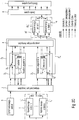
- the input-side data conversion can, as in Fig. 2A is represented by a single conversion device 1, which performs data conversion from all data formats used in studios to the data format used in the headend, or, as in Fig. 2B is represented by several individual conversion blocks 1 1 , 1 2 , ..., 1 n , each of which performs only a data conversion from a single data format used in the recording studio in the data format used in the headend realized.
- the data conversion as in Fig. 2C is represented by a redundant conversion system 1 'consisting of several redundantly executed conversion blocks 1 1 ', 1 2 ', ..., 1 n ' be realized.
- the input-side data streams generated by the data source are fed via an input-side bus system 2 to the individual identically executed processing units 3 1 , 3 2 ,..., 3 n .
- the input-side bus system 2 can be used to increase the Reliability of the head station according to the invention be designed to be redundant.
- the switching between the individual redundant input-side bus systems 2 is preferably carried out by a in the FIGS. 2A . 2 B and 2C not shown decision maker.
- the individual input-side data streams via the input-side bus system 2 are transmitted serially, and are thus no longer synchronized to each other, they must be in terms of a synchronous processing in the individual parallel processing units 3 1, 3 2, ..., are synchronized 3 n.
- synchronization data 2 - used in the individual data packets of the individual serially transmitted input-side data streams between the data source and the individual processing units 3 1 , 3 2 ,..., 3 n synchronization data - in the FIGS. 2A . 2 B and 2C referred to as synchronization data 2 - used.
- the time stamp data stored at specific data bit positions in the header of the individual data packets or the data also stored at specific data bit positions in the header of the individual data packets can be used to identify the order of the respective data packet in the respective input data stream.
- certain data bit sequences at certain data bit positions in certain data packets of the individual input data streams specified in the individual transmission standards and thus having a specified relative time interval from each other can be identified and used for the synchronization of the individual input data streams.
- the individual data packets of the individual input-side data streams are packed in the correct temporal sequence in the individual processing units 3 1 , 3 2 ,..., 3 n into the output-side data stream to be generated and synchronously with one another in the individual of the individual processing units 3 1 , 3 2 , ..., 3 n respectively generated output-side data streams.
- respective output-side data streams are generated in the identically executed processing units 3 1 , 3 2 ,..., 3 n from the individual input-side data streams supplied. Since the individual processing units 3 1 , 3 2 ,..., 3 n are typically supplied with a plurality of input-side data streams, multiplexing of the output-side data stream in the processing units 3 1 , 3 2 ,..., 3 n is a very essential processing step implemented individual input-side data streams. In addition, encoding and data formatting of the generated output-side data stream are preferably provided in the individual processing units 3 1 , 3 2 ,..., 3 n . In addition, additional processing steps customary in a preprocessing processor can be performed, which will not be discussed in more detail here.
- the output-side bus system 4 can be designed redundantly to increase the reliability of the head station according to the invention.
- the switchover between the individual redundantly executed output-side bus systems 4 is performed by a in the FIGS. 2A . 2 B and 2C not shown decision maker.
- all processing units 3 1 , 3 2 ,..., 3 n each generate an identical data stream of equal bit length, and the transmission path from each processing unit 3 1 , 3 2 ,..., 3 n to the transmitter system 6 operates without error.
- at least one processing unit 3 1 , 3 2 ,..., 3 n will respectively generate a faulty data stream and / or at least one transmission path from a processing unit 3 1 , 3 2 ,..., 3 n will fail to the transmitter system 6.
- step S 50 On the basis of the output-side data streams and status data respectively generated in the individual processing units 3 1 , 3 2 ,..., 3 n , in the following method step S 50, in each case one of the decision maker systems or a plurality of redundant decision-making systems Processing unit 3 1 , 3 2 , ..., 3 n to the associated transmission link 5 1 , 5 2 , ..., 5 n between the respective processing unit 3 1 , 3 2 , ..., 3 n and the transmitter system 6 to transmitting data stream selected on the output side.
- the selection of the individual processing units 3 1, 3 2, ..., 3 n are each to be transmitted output-side data stream from all processing units 3 1, 3 2, ..., 3 n are each generated output side Data streams performed in a decision maker.
- This may be a single decider or preferably according to Fig. 2A to a redundant decision-making system 7 from a plurality of redundantly executed decision makers 7 1 , 7 2 , ..., 7 n act.
- Each individual arbiters 7 1, 7 2, ... 7 n connected to the output-side bus system 4 and thus has access to the in all processing units 3 1, 3 2, ..., 3 n output-side data streams and status respectively generated Dates.
- a redundant decision system 7 with a plurality of redundant design decision makers 7 1, 7 2, ..., 7 n generates each individual arbiters 7 1, 7 2, ..., 7 n from the supplied output-side data streams and state data Control data for the individual processing units 3 1 , 3 2 ,..., 3 n in the mentioned manner.
- the correct decision makers 7 1 , 7 2 , ..., 7 n identified and their generated control data to the individual processing units 3 1 , 3 2 , ..., 3 n continued.
- the respective processing unit 3 1 , 3 2 ,..., 3 n and the respective transmission path 5 1 , 5 2 ,..., 5 n between the respective processing unit 3 1 , 3 2 ,. 3 n and the transmitter system 6 the respective processing unit 3 1 , 3 2 , ..., 3 n by means of the control data for a transmission of an output-side data stream on the associated transmission link 5 1 , 5 2 , ..., 5 n between the respective processing unit 3 1 , 3 2 , ..., 3 n and the transmission system 6 is activated.
- the activated processing unit 3 1, 3 2, ..., 3 n is initiated via the associated control data, in the case of one of the respective processing unit 3 1, 3 2, ..., 3 output-side data stream correctly produced n the respectively correct generated output-side data stream on the associated transmission link 5 1 , 5 2 , ..., 5 n to Transmitter system 6 and in the case of one of the respective processing unit 3 1 , 3 2 , ..., 3 n erroneously generated output-side data stream to each of a different processing unit 3 1 , 3 2 , ..., 3 n correctly generated output-side data stream to transmit ,
- a processing unit 3 1, 3 2, ..., 3 n correctly produced output-side data streams of a predetermined processing unit 3 1, 3 2, ..., 3 n are each generated output-side data stream for the selection in the respective processing unit 3 1 , 3 2 , ..., 3 n are prioritized.
- the selection of the individual processing units 3 1, 3 2, ..., 3 n are each to be transmitted output-side data stream from all processing units 3 1, 3 2, ..., 3 n are each generated output side Data streams through a according Fig. 2B implemented within a single acting as a master processing unit processing unit 3 1 integrated decision maker, which consists either as a single decider or as a redundant decision-making system with multiple redundant decision makers.
- a decision maker integrated, which consists either as a single decider or as a redundant decision-making system with multiple redundant decision makers.
- This decision maker determines the control data for the associated processing unit 3 1 , 3 2 ,..., 3 n from the respective processing unit 3 1 , 3 2 ,..., 3 n via the output-side bus system 4 from the respective other processing units 3 1 , 3 2 , ..., 3 n respectively supplied output-side data streams and state data and the output-side data stream and state data generated in the associated processing unit 3 1 , 3 2 , ..., 3 n .
- the selection of the of the respective processing unit 3 1, 3 2, ..., 3 n to the transmitter system 6 to be transmitted, output-side data stream from the respective in the processing unit 3 1, 3 2, ..., 3 n output-side data stream generated and bagepufferten or one in another processing unit 3 1 , 3 2 , ..., 3 n generated, on the output side bus system 4 and transmitted in the respective processing unit 3 1 , 3 2 , ..., 3 n buffered output data stream is effected by driving a in the respective processing unit 3 1 , 3 2 , ..., 3 n realized switch 8 1 , 8 2 , ..., 8 n by means of the respective processing unit 3 1 , 3 2 , ..., 3 n from one of the decision makers supplied control data.
- the switchover takes place between two output-side data streams in the individual switches 8 1 , 8 2 , ..., 8 n are each delayed by the transmission time of a data frame.
- each processing unit 3 1, 3 2 receives, ..., 3 n of a synchronization unit 9 - for example, a receiving unit for the G lobal- P osition- S ystem- (GPS) signal or the DCF77 Signal, each serving as reference time signals - each synchronization data, which in the FIGS. 2A . 2 B and 2C be referred to as synchronization data 2.
- a synchronization unit 9 for example, a receiving unit for the G lobal- P osition- S ystem- (GPS) signal or the DCF77 Signal
- an output-side data conversion of the output-side data streams selected in the individual processing units 3 1 , 3 2 ,..., 3 n and transmitted to the transmitter system 6 takes place from a typically proprietary data format used in the inventive headend station to one on the Transmission path between the transmitter system 6 and the receiver system of the common wave network used data format.
- the output-side data conversion can be equivalent to the input-side conversion in method step S10 by a single conversion unit 10 according to FIG Fig. 2A be realized, which has all possible data conversions.
- the output-side data conversion can also be performed by a plurality of conversion units 10 1 , 10 2 ,..., 10 n , each of which is a data conversion only between two specific data formats.
- the output-side data conversion according to Fig. 2C be implemented redundant by a redundant conversion system 10 'consisting of several redundantly running conversion blocks 10 1 ', 10 2 ', ..., 10 n ' is realized.
- About one in Fig. 2C Not shown decision-making instance is determined which conversion block 10 1 ', 10 2 ', ..., 10 n 'works correctly and whose conversion result is therefore guided to the output of the redundant conversion system 10'.
- the converted data streams are, as in the FIGS. 2A to 2C is shown, the sender system 6 or alternatively via the output side bus system 4 and the respective processing units 3 1 , 3 2 , ..., 3 n supplied to the transmitter system 6.
- the output-side data stream to be transmitted to the transmission link 11 is composed of all in the individual transmission links 5 1 , 5 2 ,..., 5 n between the respective processing unit 3 1 , 3 2 , ..., 3 n and the transmitter system 6 each selected output-side data streams selected.
- the transmitter system 6 recognizes on the basis of the individual transmission links 5 1 , 5 2 , ..., 5 n respectively received output-side data streams, which transmission links 5 1 , 5 2 , ..., 5 n are faulty.
- the invention is not limited to the individual embodiments of the head station according to the invention and the associated method according to the invention.
- the invention covers in particular all combinations of the features claimed in the individual patent claims, the features disclosed in the description and the features illustrated in the individual figures of the drawing.
Description
Die Erfindung betrifft eine Kopfstation (engl. Headstation) mit Redundanz und ein zugehöriges Betriebs-Verfahren.The invention relates to a head station with redundancy and an associated operating method.
Redundant ausgelegte Kommunikationssysteme bestehen typischerweise aus zwei Kommunikationssystemen, die gleichzeitig und unabhängig voneinander jeweils einen Ausgangsdatenstrom erzeugen. Aus der
In einer in
Fällt bei dieser Anordnung eines redundant ausgelegten Kommunikationssystems der Entscheider aus, so wird nachteilig kein Ausgangsdatenstrom über die Übertragungsstrecke übertragen. Der Entscheider wird somit zur kritischen Komponente im redundant ausgelegten Kommunikationssystem (so genannter Single-Point-of-Failure, deutsch: Ein-Punkt-Fehler). Sind die beiden Ausgangsdatenströme nicht zueinander synchronisiert, kann zusätzlich nachteilig im Entscheider keine phasenkohärente Umschaltung zwischen den beiden Ausgangsdatenströmen zur Weiterleitung eines lückenlosen Ausgangsdatenstroms an die Übertragungsstrecke durchgeführt werden.If the decision maker fails in this arrangement of a redundantly designed communication system, then disadvantageously no output data stream is transmitted over the transmission link. The decision maker thus becomes the critical component in the redundantly designed Communication system (so-called single-point-of-failure, German: one-point error). If the two output data streams are not synchronized with one another, disadvantageously no phase-coherent switching between the two output data streams can be carried out in the decider in order to forward a gapless output data stream to the transmission link.
Die
Die
Aufgabe der Erfindung ist es deshalb, eine redundant ausgelegte Kopfstation in einem Kommunikationssystem, insbesondere in einem Rundfunkübertragungssystem, insbesondere mit Gleichwellenbetrieb, derart weiterzuentwickeln, dass die obig genannten Nachteile nicht mehr auftreten.The object of the invention is therefore to further develop a redundantly designed head station in a communication system, in particular in a radio transmission system, in particular with constant wave operation, such that the disadvantages mentioned above no longer occur.
Die Aufgabe wird durch die erfindungsgemäße Kopfstation mit den Merkmalen des Patentanspruchs 1 und durch das zugehörige erfindungsgemäße Verfahren mit den Merkmalen des Patentanspruchs 14 gelöst. Vorteilhafte technische Erweiterungen sind in den jeweils abhängigen Patentansprüchen aufgeführt.The object is achieved by the head station according to the invention with the features of
In einer erfindungsgemäßen Kopfstation mit Redundanz sind mehrere identische Verarbeitungseinheiten vorgesehen, die jeweils von mindestens einem identischen eingangsseitigen Datenstrom versorgt werden. In jeder Verarbeitungseinheit wird jeweils ein ausgangsseitiger Datenstrom mittels Durchführung mehrerer Verarbeitungsschritte - beispielsweise Kodierung, Multiplexen, Datenformatierung usw. - aus dem mindestens einen eingangsseitigen Datenstrom erzeugt. Die Ausgänge jeder Verarbeitungseinheit sind über ein ausgangsseitiges Bussystem miteinander verbunden. Über das ausgangsseitige Bussystem werden zwischen den einzelnen Verarbeitungseinheiten die von den einzelnen Verarbeitungseinheiten erzeugten ausgangsseitigen Datenströme und Zustands-Daten ausgetauscht. Die Zustands-Daten enthalten z.B. Informationen über die Funktionsfähigkeit der jeweiligen Verarbeitungseinheit und der Übertragungsstrecke zwischen der jeweiligen Verarbeitungseinheit und dem Sendersystem.In a head station according to the invention with redundancy, a plurality of identical processing units are provided which are each supplied by at least one identical input-side data stream. In each processing unit, an output-side data stream is generated in each case by carrying out a plurality of processing steps-for example, coding, multiplexing, data formatting, etc. -from the at least one input-side data stream. The outputs of each processing unit are interconnected via an output-side bus system. About the output side bus system are between the individual Processing units exchanged the output-side data streams and status data generated by the individual processing units. The status data contain, for example, information about the functionality of the respective processing unit and the transmission path between the respective processing unit and the transmitter system.
Zusätzlich weist die erfindungsgemäße Kopfstation zumindest zwei Entscheider auf, die ausgehend von den zwischen den einzelnen Verarbeitungseinheiten ausgetauschten ausgangsseitigen Datenströmen und Zustands-Daten für jede Verarbeitungseinheit jeweils den ausgangsseitigen Datenstrom auswählen, der auf der zugehörigen Übertragungsstrecke zwischen der jeweiligen Verarbeitungseinheit und dem Sendersystem übertragen wird.In addition, the head station according to the invention has at least two decision makers which, on the basis of the output data streams and status data exchanged between the individual processing units, select the output-side data stream for each processing unit which is transmitted on the associated transmission link between the respective processing unit and the transmitter system.
Auf diese Weise erfolgt die Übertragung eines ausgangsseitigen Datenstroms, der aus allen von jeweils einer Verarbeitungseinheit erzeugten ausgangsseitigen Datenströmen ausgewählt wird, nicht mehr vom Entscheider zum Sendesystem. Stattdessen wird von jeder Verarbeitungseinheit entweder der von der jeweiligen Verarbeitungseinheit erzeugte ausgangsseitige Datenstrom oder der von einer anderen Verarbeitungseinheit erzeugte und über das ausgangsseitige Bussystem zur jeweiligen Verarbeitungseinheit übertragene ausgangsseitige Datenstrom über die zugeordnete Übertragungsstrecke zum Sendersystem ohne Zwischenschaltung eines Entscheiders übertragen. Das Sendersystem wählt aus allen gleichzeitig empfangenen ausgangsseitigen Datenströmen den korrekten ausgangsseitigen Datenstrom für die Übertragung über die Übertragungsstrecke zum Sendersystem aus.In this way, the transmission of an output-side data stream, which is selected from all the output-side data streams generated by a respective processing unit, no longer takes place from the decision maker to the transmission system. Instead, each processing unit transmits either the output-side data stream generated by the respective processing unit or the output-side data stream generated by another processing unit and transmitted via the output-side bus system to the respective processing unit via the assigned transmission path to the transmitter system without the intervention of a decider. The transmitter system selects from all simultaneously received output-side data streams the correct output-side data stream for transmission over the transmission link to the transmitter system.
Die Auswahl des von der jeweiligen Verarbeitungseinheit auf der zugehörigen Übertragungsstrecke zu übertragenden ausgangsseitigen Datenstroms erfolgt anhand der Verfügbarkeit der einzelnen ausgangsseitigen Datenströme in der jeweiligen Verarbeitungseinheit, anhand der Konformität der einzelnen ausgangsseitigen Datenströme mit den Anforderungen des verwendeten Übertragungsstandards und anhand der Zustands-Daten der jeweiligen Verarbeitungseinheit, die die Funktionsfähigkeit der jeweiligen Verarbeitungseinheit und die Funktionsfähigkeit der Übertragungsstrecke zwischen der jeweiligen Verarbeitungseinheit und dem Sendesystem signalisieren.The selection of the output-side data stream to be transmitted by the respective processing unit on the associated transmission path is based on the availability of the individual output-side data streams in the respective processing unit, on the conformity of the individual output-side data streams with the requirements of the transmission standard used and on the state data of the respective processing unit signaling the operability of the respective processing unit and the operability of the transmission link between the respective processing unit and the transmission system.
Um für jede Verarbeitungseinheit eine korrekte Auswahl eines über die Übertragungsstrecke zu übertragenden ausgangsseitigen Datenstroms zu garantieren, sind in der erfindungsgemäßen Kopfstation die Entscheider mittels Vorhaltung von mindestens zwei Entscheidern redundant ausgelegt. Die Identifizierung und Auswahl des jeweils korrekt funktionierenden Entscheiders - beispielsweise durch eine übergeordnete Überwachungsinstanz im Fall von zwei Entscheidern oder durch Ermittlung der ein identisches Ergebnis jeweils erzeugenden Entscheider im Fall von mindestens drei Entscheider - ist mit unterschiedlichen bekannten Verfahren möglich und wird an dieser Stelle nicht im Detail ausgeführt.In order to guarantee a correct selection of an output-side data stream to be transmitted over the transmission link for each processing unit, the decision makers in the head station according to the invention are designed to be redundant by providing at least two decoders. The identification and selection of the respectively functioning decider - for example by a higher-level monitoring authority in the case of two decision makers or by determining the decision producing an identical result in the case of at least three decision makers - is possible with different known methods and is not at this point in the Detail executed.
Die redundant ausgeführten Entscheider sind in einer ersten Ausführungsform der Erfindung jeweils außerhalb der einzelnen Verarbeitungseinheiten mit dem ausgangsseitigen Bussystem verbunden und treffen anhand der von jeder Verarbeitungseinheit auf das ausgangsseitige Bussystem übertragenen ausgangsseitigen Datenströme und Zustands-Daten für jede Verarbeitungseinheit jeweils eine Auswahl, welchen ausgangsseitigen Datenstrom die jeweilige Verarbeitungseinheit auf die zugehörige Übertragungsstrecke jeweils übertragen soll.The redundantly executed decision makers are connected in a first embodiment of the invention in each case outside the individual processing units to the output-side bus system and meet on the basis of each processing unit on the output-side bus system transmitted output-side data streams and state data for each processing unit one each Selection of which output-side data stream the respective processing unit is to transmit to the associated transmission path in each case.
Die redundant ausgeführten Entscheider sind in einer zweiten Ausführungsform der Erfindung jeweils in einer einzigen als Master-Verarbeitungseinheit agierenden Verarbeitungseinheit integriert und treffen für die als Master-Verarbeitungseinheit agierende Verarbeitungseinheit und für alle übrigen als Slave-Verarbeitungseinheiten agierenden Verarbeitungseinheiten jeweils eine Auswahl, welchen ausgangsseitigen Datenstrom die jeweilige Verarbeitungseinheit auf die zugehörige Übertragungsstrecke jeweils übertragen soll.The redundantly executed decision makers are integrated in a second embodiment of the invention in each case in a single processing unit acting as a master processing unit and make a selection for each acting as a master processing unit processing unit and for all other acting as slave processing units processing units, which output side data stream respective processing unit is to transmit to the associated transmission path respectively.
Die redundant ausgeführten Entscheider sind in einer dritten Ausführungsform der Erfindung jeweils in jeder einzelnen Verarbeitungseinheit integriert und treffen jeweils für die jeweilige Verarbeitungseinheit eine Auswahl, welchen ausgangsseitigen Datenstrom die jeweilige Verarbeitungseinheit auf die zugehörige Übertragungsstrecke jeweils übertragen soll.The redundantly executed decision makers are in each case integrated in each individual processing unit in a third embodiment of the invention and make a selection for the respective processing unit as to which output-side data stream the respective processing unit is to transmit to the respective transmission link.
Um eine sinnvolle Auswahl des auf der Übertragungstrecke vom Sendersystem zum Empfangssysteme zu übertragenden ausgangsseitigen Datenstroms durch das Sendersystem zu ermöglichen, werden die von den einzelnen Verarbeitungseinheiten jeweils ausgewählten ausgangsseitigen Datenströme erfindungsgemäß über eine Synchronisierungseinheit synchron auf der zugehörige Übertragungsstrecke zwischen der jeweiligen Verarbeitungseinheit und dem Sendersystem übertragen.In order to enable a meaningful selection of the output-side data stream to be transmitted on the transmission path from the transmitter system to the receiving system by the transmitter system, the output-side data streams respectively selected by the individual processing units are transmitted synchronously via a synchronization unit to the associated transmission link between the respective processing unit and the transmitter system.
Um eine lückenlose und damit phasenkohärente Umschaltung zwischen den auf den einzelnen Übertragungsstrecken zwischen der jeweiligen Verarbeitungseinheit und den jeweils übertragenen ausgangsseitigen Datenströmen im Sendersystem zu garantieren, erfolgt bevorzugt in jeder Verarbeitungseinheit die Umschaltung zwischen zwei auf die zugehörige Übertragungsstrecke zu übertragenden ausgangsseitigen Datenströmen jeweils nur zu den Zeitpunkten der Übergang zwischen jeweils aufeinander folgenden Datenrahmen der synchronisiert übertragenen ausgangsseitigen Datenströme.In order to guarantee a complete and therefore phase-coherent switching between the individual transmission paths between the respective processing unit and the respective transmitted output-side data streams in the transmitter system, the switching between two output data streams to be transmitted to the associated transmission path preferably takes place in each processing unit only at the times the transition between successive data frames of the synchronously transmitted output-side data streams.
Da für die Auswahl des von jeder Verarbeitungseinheit auf der Übertragungsstrecke zum Sendersystem jeweils zu übertragenden ausgangsseitigen Datenstroms jeweils eine bestimmte Verarbeitungszeit erforderlich ist, erfolgt vorzugsweise in jeder Verarbeitungseinheit die Umschaltung zwischen zwei ausgangsseitigen Datenströmen jeweils zum nächsten Übergangszeitpunkt zwischen jeweils aufeinander folgenden Datenrahmen, das heißt um die Zeitdauer für die Übertragung eines Datenrahmens verzögert.Since a specific processing time is required in each case for the selection of the output-side data stream to be transmitted by each processing unit on the transmission path to the transmitter system, the switching between two output-side data streams in each processing unit preferably takes place at the next transition time between respectively consecutive data frames, ie around the Time delay for the transmission of a data frame.
Die Versorgung der einzelnen Verarbeitungseinheiten mit identischen, von einer Datenquelle - z.B. einem Studio - jeweils erzeugten Datenströmen, die z.B. den Audio- und Videodaten von einzelnen Rundfunk-Programmen entsprechen, erfolgt über ein eingangsseitiges Bussystem.The supply of the individual processing units with identical, from a data source - e.g. a studio - respectively generated data streams, e.g. the audio and video data from individual broadcast programs correspond, via an input-side bus system.
Zur Synchronisierung der einzelnen seriell auf dem eingangsseitigen Bussystem übertragenen eingangsseitigen Datenströmen in den einzelnen Verarbeitungseinheiten werden vorzugsweise über das eingangsseitige Bussystem Synchronisierungsdaten zwischen der Datenquelle und den einzelnen Verarbeitungseinheiten übertragen. Bei den Synchronisierungsdaten kann es sich einerseits um Zeitstempel-Daten in den einzelnen Datenpaketen der einzelnen eingangsseitigen Datenströme oder um Daten zur Kennzeichnung der Reihenfolge der einzelnen Datenpakete in den einzelnen eingangsseitigen Datenströmen oder andererseits um spezifizierte, an spezifizierten Stellen in spezifizierten Datenpaketen der einzelnen eingangsseitigen Datenströme jeweils übertragene Datenbitfolgen handeln.In order to synchronize the individual input-side data streams transmitted serially on the input-side bus system in the individual processing units, synchronization data are preferably transmitted via the input-side bus system between the data source and the individual processing units. Both Synchronization data may be, on the one hand, time stamp data in the individual data packets of the individual input data streams or data for characterizing the order of the individual data packets in the individual input data streams or, on the other hand, specified data bit sequences transmitted at specific locations in specified data packets of the individual input data streams act.
Um die Redundanz der erfindungsgemäßen Kopfstation zusätzlich zu erhöhen, werden das eingangsseitige Bussystem und/oder das ausgangsseitige Bussystem bevorzugt redundant ausgelegt. Die Entscheidung, welches eingangsseitige und/oder ausgangsseitige Bussystem im jeweiligen Zeitpunkt aktiviert ist, ist beliebig.In order to additionally increase the redundancy of the head station according to the invention, the input-side bus system and / or the output-side bus system are preferably designed to be redundant. The decision as to which input-side and / or output-side bus system is activated at the respective time is arbitrary.
Um den von jeder Verarbeitungseinheit jeweils erzeugten ausgangsseitigen Datenstrom in einem Datenformat des auf der Übertragungsstrecke zwischen dem Sendersystem und dem Empfängersystem verwendeten Übertragungsstandards zu übertragen, ist ausgangsseitig bevorzugt eine Datenkonvertierung vorgesehen. Hierbei kann für jeden verwendeten Übertragungsstandard jeweils ein Konvertierungsbaustein oder ein alle Übertragungsstandards abdeckender Konvertierungsbausteinen Verwendung finden. Zur Erhöhung der Redundanz der erfindungsgemäßen Kopfstation kann die Datenkonvertierung auch redundant ausgeführt sein. Auch eingangsseitig kann im Bereich des eingangsseitigen Bussystems eine Datenkonvertierung vorgesehen werden.In order to transmit the output-side data stream respectively generated by each processing unit in a data format of the transmission standard used on the transmission link between the transmitter system and the receiver system, a data conversion is preferably provided on the output side. In this case, a conversion module or a conversion module covering all transmission standards can be used for each transmission standard used. To increase the redundancy of the head station according to the invention, the data conversion can also be designed redundantly. Also on the input side, a data conversion can be provided in the region of the input-side bus system.
Die erfindungsgemäße Kopfstation und das zugehörige erfindungsgemäße Verfahren werden im Folgenden anhand der Zeichnung im Detail erläutert. Die Figuren der Zeichnung zeigen:
- Fig. 1
- ein Blockdiagramm eines redundant Kommunikationssystems,
- Fig. 2A
- ein Blockdiagramm einer ersten Ausführungsform einer erfindungsgemäßen Kopfstation,
- Fig. 2B
- ein Blockdiagramm einer zweiten Ausführungsform einer erfindungsgemäßen Kopfstation,
- Fig. 2C
- ein Blockdiagramm einer dritten Ausführungsform einer erfindungsgemäßen Kopfstation und
- Fig. 3
- ein Flussdiagramm eines zugehörigen erfindungsgemäßen Verfahrens.
- Fig. 1
- a block diagram of a redundant communication system,
- Fig. 2A
- a block diagram of a first embodiment of a head-end station according to the invention,
- Fig. 2B
- a block diagram of a second embodiment of a head-end station according to the invention,
- Fig. 2C
- a block diagram of a third embodiment of a headend according to the invention and
- Fig. 3
- a flowchart of an associated method according to the invention.
Im Folgenden werden einzelne Ausführungsformen der erfindungsgemäßen Kopfstation anhand der Blockdiagramme in den
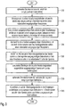
Im ersten Verfahrensschritt S10, der optional durchgeführt wird, werden die in der Datenquelle - im allgemeinen im Studio - erzeugten Datenströme - zu Programmen oder Services jeweils gehörige Video- und/oder Audio-Datenströme - bei Bedarf in ein anderes Datenformat konvertiert. Hierbei kann es sich beispielsweise um eine eingangsseitige Datenkonvertierung von einem in der Studiotechnik typischerweise verwendetes Datenformat - beispielsweise Serial-Digital-Interface-(SDI)-Datenformat oder Internet-Protocol-(IP)-Datenformat - in ein in der Kopfstation proprietär verwendetes Datenformat und/oder um eine Anpassung des zu übertragenden Datenstroms an ein verändertes Übertragungsmedium handeln.In the first method step S10, which is carried out optionally, the data streams generated in the data source, generally in the studio, are converted into programs and services, respectively associated video and / or audio data streams, if necessary into a different data format. This may be, for example, an input-side data conversion of a in the Studio equipment typically used data format - for example, S erial- D igital- I nterface- (SDI) data or I nternet- P rotocol- (IP) data - to be transmitted in a proprietary used in the head-end station data format and / or an adaptation of the Data stream to act on a different transmission medium.
Die eingangsseitige Datenkonvertierung kann, wie in
Im nächsten Verfahrensschritt S20 werden die von der Datenquelle erzeugten eingangsseitigen Datenströme über ein eingangsseitiges Bussystem 2 den einzelnen identisch ausgeführten Verarbeitungseinheiten 31,32,...,3n zugeführt. Das eingangsseitige Bussystem 2 kann zur Erhöhung der Zuverlässigkeit der erfindungsgemäßen Kopfstation redundant ausgeführt sein. Die Umschaltung zwischen den einzelnen redundant ausgeführten eingangsseitigen Bussystemen 2 erfolgt bevorzugt durch eine in den
Da die einzelnen eingangsseitigen Datenströme über das eingangsseitige Bussystem 2 seriell übertragen werden und somit nicht mehr zueinander synchronisiert sind, müssen sie im Hinblick auf eine synchrone Verarbeitung in den einzelnen parallelen Verarbeitungseinheiten 31, 32, ..., 3n synchronisiert werden. Hierzu werden in den einzelnen Datenpaketen der einzelnen seriell übertragenen eingangsseitigen Datenströme zwischen der Datenquelle und den einzelnen Verarbeitungseinheiten 31, 32, ..., 3n Synchronisierungsdaten - in den
Mithilfe dieser Synchronisierungsdaten werden die einzelnen Datenpakete der einzelnen eingangsseitigen Datenströme in der richtigen zeitlichen Reihenfolge in den einzelnen Verarbeitungseinheiten 31, 32, ..., 3n in den zu erzeugenden ausgangsseitigen Datenstrom gepackt und zeitsynchron zueinander in den einzelnen von den einzelnen Verarbeitungseinheiten 31, 32, ..., 3n jeweils erzeugten ausgangsseitigen Datenströmen übertragen.With the aid of this synchronization data, the individual data packets of the individual input-side data streams are packed in the correct temporal sequence in the individual processing units 3 1 , 3 2 ,..., 3 n into the output-side data stream to be generated and synchronously with one another in the individual of the individual processing units 3 1 , 3 2 , ..., 3 n respectively generated output-side data streams.
Im darauffolgenden Verfahrensschritt S30 werden in den identisch ausgeführten Verarbeitungseinheiten 31, 32, ..., 3n jeweils ausgangsseitige Datenströme aus den einzelnen zugeführten eingangsseitigen Datenströmen erzeugt. Da den einzelnen Verarbeitungseinheiten 31, 32, ..., 3n typischerweise mehrere eingangsseitigen Datenströme zugeführt werden, ist in den Verarbeitungseinheiten 31, 32, ..., 3n als ganz wesentlicher Verarbeitungsschritt das Multiplexen des ausgangsseitigen Datenstroms aus den einzelnen eingangsseitigen Datenströmen realisiert. Daneben ist in den einzelnen Verarbeitungseinheiten 31, 32, ..., 3n auch ein Kodieren und eine Datenformatierung des erzeugten ausgangsseitigen Datenstroms bevorzugt vorgesehen. Daneben können zusätzliche in einem Vorverarbeitungsprozessor übliche Verarbeitungsschritte durchgeführt werden, auf die an dieser Stelle nicht näher eingegangen wird.In the subsequent method step S30, respective output-side data streams are generated in the identically executed processing units 3 1 , 3 2 ,..., 3 n from the individual input-side data streams supplied. Since the individual processing units 3 1 , 3 2 ,..., 3 n are typically supplied with a plurality of input-side data streams, multiplexing of the output-side data stream in the processing units 3 1 , 3 2 ,..., 3 n is a very essential processing step implemented individual input-side data streams. In addition, encoding and data formatting of the generated output-side data stream are preferably provided in the individual processing units 3 1 , 3 2 ,..., 3 n . In addition, additional processing steps customary in a preprocessing processor can be performed, which will not be discussed in more detail here.
Im nächsten Verfahrensschritt S40 werden die in den einzelnen Verarbeitungseinheiten 31, 32, ..., 3n jeweils erzeugten ausgangsseitigen Datenströme über das ausgangsseitige Bussystem 4 zwischen den einzelnen Verarbeitungseinheiten 31, 32, ..., 3n ausgetauscht. Zusätzlich erfolgt über das ausgangsseitige Bussystem 4 auch ein Austausch der in den einzelnen Verarbeitungseinheiten 31, 32, ..., 3n erzeugten Zustands-Daten. Diese Zustands-Daten signalisieren jeweils ein korrektes Funktionieren der jeweiligen Verarbeitungseinheit 31, 32, ..., 3n und ein korrektes Funktionieren der jeweiligen Übertragungsstrecke 51, 52, ..., 5n zwischen der jeweiligen Verarbeitungseinheit 31, 32, ..., 3n und dem Sendersystem 6. Analog zum eingangsseitigen Bussystem 2 kann auch das ausgangsseitige Bussystem 4 zur Erhöhung der Zuverlässigkeit der erfindungsgemäßen Kopfstation redundant ausgelegt sein. Die Umschaltung zwischen den einzelnen redundant ausgeführten ausgangsseitigen Bussystemen 4 erfolgt durch eine in den
Im korrekten Betrieb erzeugen alle Verarbeitungseinheiten 31, 32, ..., 3n jeweils einen identischen - bitgleichen - Datenstrom und die Übertragungstrecke von jeder Verarbeitungseinheit 31, 32, ..., 3n zum Sendersystem 6 arbeitet fehlerfrei. Im Fehlerfall wird mindestens eine Verarbeitungseinheit 31, 32, ..., 3n jeweils einen fehlerhaften Datenstrom erzeugen und/oder mindestens eine Übertragungsstrecke von einer Verarbeitungseinheit 31, 32, ..., 3n zum Sendersystem 6 ausfallen. Auf der Basis der in den einzelnen Verarbeitungseinheiten 31, 32, ..., 3n jeweils erzeugten ausgangsseitigen Datenströme und Zustands-Daten wird somit im darauffolgenden Verfahrensschritt S50 in einem Entscheider-System oder mehreren redundanten Entscheider-Systemen jeweils der von der jeweiligen Verarbeitungseinheit 31, 32, ..., 3n auf die zugehörige Übertragungsstrecke 51, 52, ..., 5n zwischen der jeweiligen Verarbeitungseinheit 31, 32, ..., 3n und dem Sendersystem 6 zu übertragende ausgangsseitig Datenstrom ausgewählt.In the correct operation, all processing units 3 1 , 3 2 ,..., 3 n each generate an identical data stream of equal bit length, and the transmission path from each processing unit 3 1 , 3 2 ,..., 3 n to the
In einer ersten erfindungsgemäßen Ausführungsform wird die Auswahl des von den einzelnen Verarbeitungseinheiten 31, 32, ..., 3n jeweils zu übertragenden ausgangsseitigen Datenstroms aus den von allen Verarbeitungseinheiten 31, 32, ..., 3n jeweils erzeugten ausgangsseitigen Datenströmen in einem Entscheider durchgeführt. Hierbei kann es sich um einen einzigen Entscheider oder bevorzugt gemäß
Über die auf dem ausgangsseitigen Bussystem 4 jeweils verfügbaren ausgangsseitigen Datenströme erlangt der einzelne Entscheider 71, 72, ..., 7n die für seine Entscheidung wichtige Information, welche Verarbeitungseinheit 31, 32, ..., 3n überhaupt keinen ausgangsseitigen Datenstrom erzeugt hat und somit keine korrekte Funktionsweise aufweist. Der Vergleich der einzelnen ausgangsseitigen Datenströme mit den Vorgaben des im Gleichwellennetz verwendeten Übertragungsstandards - beispielsweise ATSC-M/H, DVB-T oder DVB-T2 - liefert dem einzelnen Entscheider 71, 72, ..., 7n eine weitere für die Entscheidung wichtige Information, welche Verarbeitungseinheit 31, 32, ..., 3n korrekt funktioniert bzw. fehlerhaft betrieben wird. Aus den über das ausgangsseitige Bussystem 4 den einzelnen Entscheidern 71, 72, ..., 7n jeweils zugeführten und in den einzelnen Verarbeitungseinheiten 31, 32, ..., 3n jeweils erzeugten Zustands-Daten erhält der jeweilige Entscheider 71, 72, ..., 7n eine weitere für die Entscheidung wichtige Information, welche Verarbeitungseinheit 31, 32, ..., 3n und welche zugeordnete Übertragungsstrecke 51, 52, ..., 5n zwischen der jeweiligen Verarbeitungseinheit 31, 32, ..., 3n und dem Sendesystem 6 jeweils korrekt oder fehlerbehaftet arbeitet.Via the respectively available on the output-
Im Fall eines redundanten Entscheider-System 7 mit mehreren redundant ausgeführten Entscheidern 71, 72, ..., 7n erzeugt jeder einzelne Entscheider 71, 72, ..., 7n aus den zugeführten ausgangsseitigen Datenströmen und Zustands-Daten in der erwähnten Art und Weise jeweils Steuer-Daten für die einzelnen Verarbeitungseinheiten 31, 32, ..., 3n. Über eine zusätzliche Entscheider-Instanz, die in den einzelnen
Im Fall eines korrekten Betriebs der jeweiligen Verarbeitungseinheit 31, 32, ..., 3n und der jeweiligen Übertragungsstrecke 51, 52, ..., 5n zwischen der jeweiligen Verarbeitungseinheit 31, 32, ..., 3n und dem Sendersystem 6 wird die jeweilige Verarbeitungseinheit 31, 32, ..., 3n mittels der Steuer-Daten für eine Übertragung eines ausgangsseitigen Datenstroms auf der zugeordneten Übertragungsstrecke 51, 52, ..., 5n zwischen der jeweiligen Verarbeitungseinheit 31, 32, ..., 3n und dem Sendesystem 6 aktiviert. Die aktivierte Verarbeitungseinheit 31, 32, ..., 3n wird über die zugeordneten Steuer-Daten veranlasst, im Fall eines von der jeweiligen Verarbeitungseinheit 31, 32, ..., 3n korrekt erzeugten ausgangsseitigen Datenstroms den jeweils korrekt erzeugten ausgangsseitigen Datenstrom auf der zugeordneten Übertragungsstrecke 51, 52, ..., 5n zum Sendesystem 6 und im Fall eines von der jeweiligen Verarbeitungseinheit 31, 32, ..., 3n fehlerhaft erzeugten ausgangsseitigen Datenstroms den jeweils von einer anderen Verarbeitungseinheit 31, 32, ..., 3n korrekt erzeugten ausgangsseitigen Datenstrom zu übertragen. Im letzteren Fall kann bei Vorliegen von mehreren durch jeweils eine Verarbeitungseinheit 31, 32, ..., 3n korrekt erzeugten ausgangsseitigen Datenströmen der von einer vorab bestimmten Verarbeitungseinheit 31, 32, ..., 3n jeweils erzeugte ausgangsseitige Datenstrom für die Auswahl in der jeweiligen Verarbeitungseinheit 31, 32, ..., 3n priorisiert werden.In the case of a correct operation of the respective processing unit 3 1 , 3 2 ,..., 3 n and the respective transmission path 5 1 , 5 2 ,..., 5 n between the respective processing unit 3 1 , 3 2 ,. 3 n and the
In einer zweiten erfindungsgemäßen Ausführungsform wird die Auswahl des von den einzelnen Verarbeitungseinheiten 31, 32, ..., 3n jeweils zu übertragenden ausgangsseitigen Datenstroms aus den von allen Verarbeitungseinheiten 31, 32, ..., 3n jeweils erzeugten ausgangsseitigen Datenströmen durch einen gemäß
Aus den über das ausgangsseitige Bussystem 4 der Master-Verarbeitungseinheit 31 von den übrigen Verarbeitungseinheiten 32, ..., 3n jeweils zugeführten ausgangsseitigen Datenströmen und Zustands-Daten und den in der Master-Verarbeitungseinheit 31 erzeugten ausgangsseitigen Datenstrom und Zustands-Daten werden die für alle Verarbeitungseinheiten 31, 32, ..., 3n jeweils benötigten Steuer-Daten generiert. Für den Fall eines aus mehreren redundant ausgeführten Entscheidern zusammengesetzten redundanten Entscheider-Systems innerhalb einer Master-Verarbeitungseinheit 31 gilt das zu der ersten erfindungsgemäßen Ausführungsform Gesagte für das aus mehreren redundant ausgeführten Entscheidern 71, 72, ..., 7n zusammengesetzte redundante Entscheider-System äquivalent.From the output-side data streams and status data supplied in each case via the output-
In einer dritten erfindungsgemäßen Ausführungsform ist gemäß
Die Auswahl des von der jeweiligen Verarbeitungseinheit 31, 32, ..., 3n zum Sendersystem 6 zu übertragenden ausgangsseitigen Datenstroms aus dem in der jeweiligen Verarbeitungseinheit 31, 32, ..., 3nerzeugten und zwischengepufferten ausgangsseitigen Datenstrom oder einem in einer anderen Verarbeitungseinheit 31, 32, ..., 3n erzeugten, über das ausgangsseitige Bussystem 4 übertragene und in der jeweiligen Verarbeitungseinheit 31, 32, ..., 3n zwischengepufferten ausgangsseitigen Datenstrom erfolgt durch Ansteuerung eines in der jeweiligen Verarbeitungseinheit 31, 32, ..., 3n realisierten Schalters 81, 82, ..., 8n mittels der der jeweiligen Verarbeitungseinheit 31, 32, ..., 3n von einem der Entscheider zugeführten Steuerungs-Daten.The selection of the of the respective processing unit 3 1, 3 2, ..., 3 n to the
Um im Sendesystem 6 lückenlos zwischen den auf den einzelnen Übertragungsstrecken 51, 52, ...,, 5n jeweils übertragenen ausgangsseitigen Datenströme umzuschalten, ist eine phasenkohärente Übertragung der einzelnen ausgangsseitigen Datenströme auf den einzelnen Übertragungsstrecken 51, 52, ....,, 5n von der jeweiligen Verarbeitungseinheit 31, 32, ..., 3n zum Sendesystem 6 nötig. Hierzu erfolgen Schaltvorgänge in den einzelnen Schaltern 81, 82, ..., 8n jeweils nur zu den Zeitpunkten des Übergangs zwischen jeweils zwei aufeinander folgenden Datenrahmen der einzelnen ausgangsseitigen Datenströme. Da für die Ermittlung der in den einzelnen Verarbeitungseinheiten 31, 32, ..., 3n jeweils auszuwählenden ausgangsseitigen Datenströme in den einzelnen Entscheidern oder Entscheider-Systemen eine gewisse Verarbeitungszeit benötigt wird, erfolgt die Umschaltung zwischen zwei ausgangsseitigen Datenströmen in den einzelnen Schaltern 81, 82, ..., 8n jeweils um die Übertragungszeit eines Datenrahmens verzögert.In order to switch continuously in the
Im nächsten Verfahrensschritt S60 werden die in den einzelnen Verarbeitungseinheiten 31, 32, ..., 3n für die Übertragung zum Sendersystem 6 jeweils ausgewählten ausgangsseitigen Datenströme synchron auf die zugehörige Übertragungsstrecke 51, 52, ..., 5n zum Sendersystem 6 übertragen. Für die Synchronisierung der einzelnen ausgangsseitigen Datenströme erhält jede Verarbeitungseinheit 31, 32, ..., 3n von einer Synchronisierungseinheit 9 - beispielsweise eine Empfangseinheit für das Global-Position-System-(GPS)-Signal oder das DCF77-Signal, die jeweils als Referenzzeitsignale dienen - jeweils Synchronisierungsdaten, die in den
Im darauf folgenden optionalen Verfahrensschritt S70 erfolgt eine ausgangsseitige Datenkonvertierung der in den einzelnen Verarbeitungseinheiten 31, 32, ..., 3n jeweils ausgewählten und zum Sendersystem 6 übertragenen ausgangsseitigen Datenströme von einem in der erfindungsgemäßen Kopfstation verwendeten typischerweise proprietären Datenformat zu einem auf der Übertragungsstrecke zwischen Sendersystem 6 und dem Empfängersystem des Gleichwellennetzes verwendeten Datenformats. Die ausgangsseitige Datenkonvertierung kann äquivalent zur eingangsseitigen Konvertierung in Verfahrensschritt S10 durch eine einzige Konvertierungseinheit 10 gemäß
Auch kann die ausgangsseitiger Datenkonvertierung gemäß
Die konvertierten Datenströme werden, wie in den
Im abschließenden Verfahrensschritt S80 werden im Sendersystem 6, das typischerweise aus mehreren regional verteilten Sendeanlagen besteht, der auf die Übertragungsstrecke 11 zu übertragende ausgangsseitige Datenstrom aus allen in den einzelnen Übertragungsstrecken 51, 52, ..., 5n zwischen der jeweiligen Verarbeitungseinheit 31, 32, ..., 3n und dem Sendersystem 6 jeweils übertragenen ausgangsseitigen Datenströmen ausgewählt. Das Sendersystem 6 erkennt anhand der auf den einzelnen Übertragungsstrecken 51, 52, ..., 5n jeweils empfangenen ausgangsseitigen Datenströme, welche Übertragungsstrecken 51, 52, ..., 5n fehlerbehaftet sind. Für den Fall, dass eine Übertragungsstrecke 51, 52, ..., 5n, aus der das Sendersystem 6 den ausgangsseitigen Datenstrom für eine Weiterleitung zur Übertragungsstrecke 11 zwischen dem Sendersystem 6 und dem Empfängersystem bisher ausgewählt hat, nach einem korrekten Betrieb in einen fehlerbehafteten Betrieb übergeht, erfolgt eine Umschaltung auf einen ausgangsseitigen Datenstrom, der auf einer aktuell korrekt funktionierenden Übertragungsstrecke 51, 52, ..., 5n übertragen wird. Die Umschaltung zwischen den beiden ausgangsseitigen Datenströmen erfolgt dabei lückenfrei, da die auf allen Übertragungsstrecken 51, 52, ..., 5n jeweils übertragenen ausgangsseitigen Datenströme synchron und phasenkohärent übertragen werden.In the concluding method step S80, in the
Die Erfindung ist nicht auf die einzelnen Ausführungsformen der erfindungsgemäßen Kopfstation und des zugehörigen erfindungsgemäßen Verfahrens beschränkt. Von der Erfindung sind insbesondere alle Kombinationen der in den einzelnen Patentansprüchen beanspruchten Merkmale, der in der Beschreibung offenbarten Merkmale und der in den einzelnen Figuren der Zeichnung dargestellten Merkmale mit abgedeckt.The invention is not limited to the individual embodiments of the head station according to the invention and the associated method according to the invention. The invention covers in particular all combinations of the features claimed in the individual patent claims, the features disclosed in the description and the features illustrated in the individual figures of the drawing.
Claims (20)
- Head end station with
at least two identical processing units (31, 32, ..., 3n) which are each supplied with at least one identical input side data stream and generate an output side data stream,
an output side bus system (4) connected with the processing units (31, 32, ..., 3n) for exchanging output side data streams and status data generated in each of the processing units (31, 32, ..., 3n),
at least two decision elements (71, 72, ..., 7n; 7; 71'; 71", 72", ..., 7n") connected with the output side bus system (4) for selecting the output side data stream in each processing unit (31, 32, ..., 3n) to be transmitted to a transmitter system (6) from all the data streams and status data generated in each of the individual processing units (31, 32, ..., 3n) and
a synchronising unit (9) for synchronous transmission of the output side data stream selected and to be transmitted to the transmitter system (6) from each processing unit (31, 32, ..., 3n),
wherein the decision elements (71, 72, ..., 7n; 7; 71'; 71", 72", ..., 7n") are designed so as to be redundant. - Head end station according to claim 1,
characterised in that
the decision elements (71, 72, ..., 7n; 7) which are designed so as to be redundant are arranged outside the processing units (31, 32, ..., 3n), wherein each decision element (71, 72, ..., 7n; 7) is responsible for selecting the output side data stream to be transmitted to the transmitter system (6) from each processing unit (31, 32, ..., 3n). - Head end station according to claim 1,
characterised in that
the decision elements (71', ...) which are designed so as to be redundant are integrated in a single processing unit (31,32, ..., 3n), wherein the decision elements (71', ...) which are designed so as to be redundant are responsible for selecting the output side data stream to be transmitted to the transmitter system (6) from each processing unit (31, 32, ..., 3n). - Head end station according to claim 1,
characterised in that
decision elements (71", 72", ,.., 7n") which are designed so as to be redundant are integrated in each processing unit (31, 32, ..., 3n), wherein the decision elements (71", 72", ..., 7n") which are designed so as to be redundant in the respective processing unit (31, 32, ..., 3n) are responsible for selecting the output side data stream to be transmitted to the transmitter system (6) from the respective processing unit (31, 32, ..., 3n). - Head end station according to one of claims 1 to 4,
characterised in that
the selection of the output side data stream to be transmitted to the transmitter system (6) from the respective processing unit (31, 32, ..., 3n) is made at the transitions between successive data frames of the output side data stream to be transmitted synchronously. - Head end station according to one of claims 1 to 5,
characterised in that
the transmission of the output side data streams to be transmitted synchronously to the transmitter system (6) is carried out delayed by the transmission time of one data frame. - Head end station according to one of claims 1 to 6,
characterised in that
the selection of the output side data stream to be transmitted to the transmitter system (6) from the respective processing unit (31, 32, ..., 3n) is made on the basis of the availability of the output side data streams to be selected in the respective processing unit (31, 32, ..., 3n) and/or the conformity of the output side data streams to be selected with requirements of the particular transmission standard used and/or the status data characterising the operability of the respective processing unit (31, 32, ..., 3n) and the particular transmission path (51, 52, ..., 5n) from the respective processing unit (31, 32, ..., 3n) to the transmitter system (6). - Head end station according to one of claims 1 to 7,
characterised in that
an input side bus system (2) is provided to supply the individual processing units (31, 32,..., 3n) with identical input side data streams generated from one data source in each case. - Head end station according to claim 8,
characterised in that
synchronisation of the input side data streams is carried out by means of exchanging of synchronising data over the input side bus system (2). - Head end station according to claim 9,
characterised in that
the synchronising data is time stamp data transmitted in each case in data packets of the individual input side data streams and/or data for characterising a sequence of data packets in individual input side data streams and/or a specified data bit sequence transmitted at a specified place in specified data packets in individual input side data streams. - Head end station according to one of claims 8 to 10,
characterised in that
the input side bus system (2) and/or the output side bus system (4) are designed so as to be redundant. - Head end station according to one of claims 1 to 11,
characterised in that
at least one converting unit (10; 101, 102, ..., 10n; 101', 102', ..., 10n', 10') is provided for converting the data of the selected output side data streams to be transmitted to the transmitter system (6) into a data format of a transmission standard used. - Head end station according to claim 12,
characterised in that
the converting units (101', 102', ..., 10n', 10') are designed so as to be redundant. - Method for selecting an output side data stream in identical processing units (31, 32, ..., 3n) of a head end station to be transmitted in each case to a transmitter system (6) with the following method steps:• . generation of an output side data stream in each processing unit (31, 32, ..., 3n) from at least one input side data stream supplied to the respective processing unit (31, 32, ..., 3n),• . exchange of the output side data streams and status data generated in each of the processing units (31, 32, ..., 3n) over an output side bus system (4) connected with the processing units (31, 32, ..., 3n),• . selection of the output side data stream in each processing unit (31, 32, ..., 3n) to be transmitted to the transmitter system (6) by means of at least two at least two decision elements (71, 72, ..., 7n; 7; 71'; 71", 72", ..., 7n") connected with the output side bus system (4) to which in each case all the data streams and status data generated in the individual processing units (31, 32, ..., 3n) are supplied, and• . synchronous transmission of the output side data stream selected in each case for each processing unit (31, 32, ..., 3n) to the transmitter system (6), wherein the decision elements (71 ... 7n) are used redundantly.
- Method according to claim 14,
characterised in that
the synchronous transmission of the individual output side data streams to the transmitter system (6) is carried out at the transitions between successive data frames of the output side data streams to be transmitted synchronously. - Method according to claim 14 or 15,
characterised in that
the synchronous transmission of the individual output side data streams to the transmitter system (6) is carried out delayed by the transmission time of one data frame. - Method according to one of claims 14 to 16,
characterised in that
the selection of the output side data stream to be transmitted to the transmitter system (6) from the respective processing unit (31, 32, ..., 3n) is made on the basis of the availability of the output side data streams to be selected in the respective processing unit and/or the conformity of the output side data streams to be selected with requirements of the particular transmission standard used and/or the status data characterising the operability of the respective processing unit (31, 32, ..., 3n) and the particular transmission path (51, 52, ..., 5n) from the respective processing unit (31, 32, ..., 3n) to the transmitter system (6). - Method according to one of claims 14 to 17,
characterised in that
the individual processing units (31, 32, ..., 3n) are supplied with identical input side data streams generated from one data source in each case over an input side bus system (2). - Method according to claim 18,
characterised in that
the input side data streams are synchronised by means of exchanging of synchronising data over the input side bus system (2). - Method according to one of claims 14 to 19,
characterised in that
the selected output side data streams to be transmitted to the transmitter system (6) are converted by means of converting units (10; 101, 102, ..., 10n; 101', 102', ..., 10n', 10') into a data format of a transmission standard used.
Applications Claiming Priority (2)
| Application Number | Priority Date | Filing Date | Title |
|---|---|---|---|
| DE102011083816A DE102011083816A1 (en) | 2011-09-30 | 2011-09-30 | Headend with redundancy and associated procedure |
| PCT/EP2012/065501 WO2013045160A1 (en) | 2011-09-30 | 2012-08-08 | Headend with redundancy, and an associated method |
Publications (2)
| Publication Number | Publication Date |
|---|---|
| EP2761792A1 EP2761792A1 (en) | 2014-08-06 |
| EP2761792B1 true EP2761792B1 (en) | 2016-10-05 |
Family
ID=46704603
Family Applications (1)
| Application Number | Title | Priority Date | Filing Date |
|---|---|---|---|
| EP12748415.2A Active EP2761792B1 (en) | 2011-09-30 | 2012-08-08 | Headend station having redundancy and associated method |
Country Status (6)
| Country | Link |
|---|---|
| US (1) | US9703746B2 (en) |
| EP (1) | EP2761792B1 (en) |
| CN (1) | CN103828271B (en) |
| BR (1) | BR112014006889B1 (en) |
| DE (1) | DE102011083816A1 (en) |
| WO (1) | WO2013045160A1 (en) |
Families Citing this family (1)
| Publication number | Priority date | Publication date | Assignee | Title |
|---|---|---|---|---|
| DE102018000559A1 (en) * | 2018-01-24 | 2019-07-25 | WAGO Verwaltungsgesellschaft mit beschränkter Haftung | SYSTEM FOR GENERATING A DATA FLOW BASED ON REDUNDANT INFORMATION |
Family Cites Families (7)
| Publication number | Priority date | Publication date | Assignee | Title |
|---|---|---|---|---|
| DE10011267A1 (en) | 2000-03-08 | 2001-09-13 | Tenovis Gmbh & Co Kg | Communication module for bus operation as well as a system with several communication modules |
| DE10291055D2 (en) * | 2001-03-15 | 2004-04-15 | Bosch Gmbh Robert | Method for controlling a component of a distributed security-relevant system |
| US7336646B2 (en) | 2004-10-26 | 2008-02-26 | Nokia Corporation | System and method for synchronizing a transport stream in a single frequency network |
| JP2006129355A (en) * | 2004-11-01 | 2006-05-18 | Internatl Business Mach Corp <Ibm> | Information processor, data transmission system, data transmission method, and program for performing the data transmission method on the information processor |
| US7979746B2 (en) * | 2009-04-27 | 2011-07-12 | Honeywell International Inc. | Dual-dual lockstep processor assemblies and modules |
| DE102009051494A1 (en) * | 2009-07-27 | 2011-02-03 | Rohde & Schwarz Gmbh & Co. Kg | Distributor head with bus system |
| US8655156B2 (en) * | 2010-03-02 | 2014-02-18 | Cisco Technology, Inc. | Auxiliary audio transmission for preserving synchronized playout with paced-down video |
-
2011
- 2011-09-30 DE DE102011083816A patent/DE102011083816A1/en not_active Withdrawn
-
2012
- 2012-08-08 US US14/240,786 patent/US9703746B2/en active Active
- 2012-08-08 EP EP12748415.2A patent/EP2761792B1/en active Active
- 2012-08-08 BR BR112014006889-5A patent/BR112014006889B1/en active IP Right Grant
- 2012-08-08 WO PCT/EP2012/065501 patent/WO2013045160A1/en active Application Filing
- 2012-08-08 CN CN201280047911.9A patent/CN103828271B/en active Active
Also Published As
| Publication number | Publication date |
|---|---|
| WO2013045160A1 (en) | 2013-04-04 |
| CN103828271A (en) | 2014-05-28 |
| BR112014006889A2 (en) | 2017-04-04 |
| DE102011083816A1 (en) | 2013-04-04 |
| CN103828271B (en) | 2016-05-04 |
| BR112014006889B1 (en) | 2022-04-05 |
| US20140207985A1 (en) | 2014-07-24 |
| US9703746B2 (en) | 2017-07-11 |
| EP2761792A1 (en) | 2014-08-06 |
Similar Documents
| Publication | Publication Date | Title |
|---|---|---|
| DE2630084C2 (en) | Time diversity data transmission system and data transmission method | |
| EP0990330B1 (en) | Redundant serial bus | |
| EP0580016B1 (en) | Local area network | |
| EP1719367B1 (en) | Multiple use of a standard interface in a device | |
| DE19626675A1 (en) | Synchronization procedure | |
| DE2612311A1 (en) | DATA LOOP BUSWAY INTERCONNECTION SYSTEM | |
| EP1365543B1 (en) | Method and apparatus for transmitting information and detection of failures in a ring network | |
| DE69634990T2 (en) | METHOD AND DEVICE FOR SWITCHING BETWEEN REDUNDANT HARDWARE IN A WIRELESS DATA TRANSMISSION SYSTEM | |
| EP2761792B1 (en) | Headend station having redundancy and associated method | |
| DE60124837T2 (en) | Method and system for frame and pointer alignment of sonet data channels | |
| EP2936692A1 (en) | Method for redundantly and securely transferring data from a data source to a data sink | |
| EP2571265B1 (en) | Rail vehicle with a video surveillance system and video surveillance system for a rail vehicle | |
| EP0100820A2 (en) | Method for the synchronous transmission of frame-structured data | |
| DE60114479T2 (en) | Dual transmission spread system for CDMA communication device | |
| DE19536518C2 (en) | Method for maintaining the microsynchronous operation of duplicate information processing units | |
| EP2550837A1 (en) | Transmission system and transmission method for the wireless transmission of signals in an automation installation, and automation installation having such a transmission system | |
| EP2282451B1 (en) | Headend with bus system | |
| EP0621701B1 (en) | Method and apparatus for the reduction of the bit error rate in the diversity transmission of digital data radio | |
| DE3843182C2 (en) | ||
| EP0522193B1 (en) | Digital coupling network | |
| DE102005024191B4 (en) | Method for operating a control system, in particular for radio stations | |
| DE3822263A1 (en) | CIRCUIT ARRANGEMENT FOR TRANSMITTING INFORMATION | |
| EP0314236B1 (en) | Method and circuit for information transmission | |
| EP1211823A1 (en) | Time multiplex method for data transmission | |
| DE10307749A1 (en) | Data transmission method for transmitting data between subscribers set up in a networked ring arranges data in frames |
Legal Events
| Date | Code | Title | Description |
|---|---|---|---|
| PUAI | Public reference made under article 153(3) epc to a published international application that has entered the european phase |
Free format text: ORIGINAL CODE: 0009012 |
|
| 17P | Request for examination filed |
Effective date: 20131108 |
|
| AK | Designated contracting states |
Kind code of ref document: A1 Designated state(s): AL AT BE BG CH CY CZ DE DK EE ES FI FR GB GR HR HU IE IS IT LI LT LU LV MC MK MT NL NO PL PT RO RS SE SI SK SM TR |
|
| DAX | Request for extension of the european patent (deleted) | ||
| 17Q | First examination report despatched |
Effective date: 20151030 |
|
| GRAP | Despatch of communication of intention to grant a patent |
Free format text: ORIGINAL CODE: EPIDOSNIGR1 |
|
| INTG | Intention to grant announced |
Effective date: 20160316 |
|
| GRAS | Grant fee paid |
Free format text: ORIGINAL CODE: EPIDOSNIGR3 |
|
| GRAA | (expected) grant |
Free format text: ORIGINAL CODE: 0009210 |
|
| AK | Designated contracting states |
Kind code of ref document: B1 Designated state(s): AL AT BE BG CH CY CZ DE DK EE ES FI FR GB GR HR HU IE IS IT LI LT LU LV MC MK MT NL NO PL PT RO RS SE SI SK SM TR |
|
| REG | Reference to a national code |
Ref country code: GB Ref legal event code: FG4D Free format text: NOT ENGLISH |
|
| REG | Reference to a national code |
Ref country code: CH Ref legal event code: EP |
|
| REG | Reference to a national code |
Ref country code: AT Ref legal event code: REF Ref document number: 835413 Country of ref document: AT Kind code of ref document: T Effective date: 20161015 |
|
| REG | Reference to a national code |
Ref country code: IE Ref legal event code: FG4D Free format text: LANGUAGE OF EP DOCUMENT: GERMAN |
|
| REG | Reference to a national code |
Ref country code: DE Ref legal event code: R096 Ref document number: 502012008438 Country of ref document: DE |
|
| REG | Reference to a national code |
Ref country code: NL Ref legal event code: MP Effective date: 20161005 |
|
| REG | Reference to a national code |
Ref country code: LT Ref legal event code: MG4D |
|
| PG25 | Lapsed in a contracting state [announced via postgrant information from national office to epo] |
Ref country code: LV Free format text: LAPSE BECAUSE OF FAILURE TO SUBMIT A TRANSLATION OF THE DESCRIPTION OR TO PAY THE FEE WITHIN THE PRESCRIBED TIME-LIMIT Effective date: 20161005 |
|
| PG25 | Lapsed in a contracting state [announced via postgrant information from national office to epo] |
Ref country code: SE Free format text: LAPSE BECAUSE OF FAILURE TO SUBMIT A TRANSLATION OF THE DESCRIPTION OR TO PAY THE FEE WITHIN THE PRESCRIBED TIME-LIMIT Effective date: 20161005 Ref country code: LT Free format text: LAPSE BECAUSE OF FAILURE TO SUBMIT A TRANSLATION OF THE DESCRIPTION OR TO PAY THE FEE WITHIN THE PRESCRIBED TIME-LIMIT Effective date: 20161005 Ref country code: GR Free format text: LAPSE BECAUSE OF FAILURE TO SUBMIT A TRANSLATION OF THE DESCRIPTION OR TO PAY THE FEE WITHIN THE PRESCRIBED TIME-LIMIT Effective date: 20170106 Ref country code: NO Free format text: LAPSE BECAUSE OF FAILURE TO SUBMIT A TRANSLATION OF THE DESCRIPTION OR TO PAY THE FEE WITHIN THE PRESCRIBED TIME-LIMIT Effective date: 20170105 |
|
| PG25 | Lapsed in a contracting state [announced via postgrant information from national office to epo] |
Ref country code: FI Free format text: LAPSE BECAUSE OF FAILURE TO SUBMIT A TRANSLATION OF THE DESCRIPTION OR TO PAY THE FEE WITHIN THE PRESCRIBED TIME-LIMIT Effective date: 20161005 Ref country code: IS Free format text: LAPSE BECAUSE OF FAILURE TO SUBMIT A TRANSLATION OF THE DESCRIPTION OR TO PAY THE FEE WITHIN THE PRESCRIBED TIME-LIMIT Effective date: 20170205 Ref country code: PL Free format text: LAPSE BECAUSE OF FAILURE TO SUBMIT A TRANSLATION OF THE DESCRIPTION OR TO PAY THE FEE WITHIN THE PRESCRIBED TIME-LIMIT Effective date: 20161005 Ref country code: HR Free format text: LAPSE BECAUSE OF FAILURE TO SUBMIT A TRANSLATION OF THE DESCRIPTION OR TO PAY THE FEE WITHIN THE PRESCRIBED TIME-LIMIT Effective date: 20161005 Ref country code: NL Free format text: LAPSE BECAUSE OF FAILURE TO SUBMIT A TRANSLATION OF THE DESCRIPTION OR TO PAY THE FEE WITHIN THE PRESCRIBED TIME-LIMIT Effective date: 20161005 Ref country code: RS Free format text: LAPSE BECAUSE OF FAILURE TO SUBMIT A TRANSLATION OF THE DESCRIPTION OR TO PAY THE FEE WITHIN THE PRESCRIBED TIME-LIMIT Effective date: 20161005 Ref country code: PT Free format text: LAPSE BECAUSE OF FAILURE TO SUBMIT A TRANSLATION OF THE DESCRIPTION OR TO PAY THE FEE WITHIN THE PRESCRIBED TIME-LIMIT Effective date: 20170206 Ref country code: ES Free format text: LAPSE BECAUSE OF FAILURE TO SUBMIT A TRANSLATION OF THE DESCRIPTION OR TO PAY THE FEE WITHIN THE PRESCRIBED TIME-LIMIT Effective date: 20161005 |
|
| REG | Reference to a national code |
Ref country code: DE Ref legal event code: R097 Ref document number: 502012008438 Country of ref document: DE |
|
| REG | Reference to a national code |
Ref country code: FR Ref legal event code: PLFP Year of fee payment: 6 |
|
| PG25 | Lapsed in a contracting state [announced via postgrant information from national office to epo] |
Ref country code: SK Free format text: LAPSE BECAUSE OF FAILURE TO SUBMIT A TRANSLATION OF THE DESCRIPTION OR TO PAY THE FEE WITHIN THE PRESCRIBED TIME-LIMIT Effective date: 20161005 Ref country code: CZ Free format text: LAPSE BECAUSE OF FAILURE TO SUBMIT A TRANSLATION OF THE DESCRIPTION OR TO PAY THE FEE WITHIN THE PRESCRIBED TIME-LIMIT Effective date: 20161005 Ref country code: DK Free format text: LAPSE BECAUSE OF FAILURE TO SUBMIT A TRANSLATION OF THE DESCRIPTION OR TO PAY THE FEE WITHIN THE PRESCRIBED TIME-LIMIT Effective date: 20161005 Ref country code: RO Free format text: LAPSE BECAUSE OF FAILURE TO SUBMIT A TRANSLATION OF THE DESCRIPTION OR TO PAY THE FEE WITHIN THE PRESCRIBED TIME-LIMIT Effective date: 20161005 Ref country code: EE Free format text: LAPSE BECAUSE OF FAILURE TO SUBMIT A TRANSLATION OF THE DESCRIPTION OR TO PAY THE FEE WITHIN THE PRESCRIBED TIME-LIMIT Effective date: 20161005 |
|
| PLBE | No opposition filed within time limit |
Free format text: ORIGINAL CODE: 0009261 |
|
| STAA | Information on the status of an ep patent application or granted ep patent |
Free format text: STATUS: NO OPPOSITION FILED WITHIN TIME LIMIT |
|
| PG25 | Lapsed in a contracting state [announced via postgrant information from national office to epo] |
Ref country code: IT Free format text: LAPSE BECAUSE OF FAILURE TO SUBMIT A TRANSLATION OF THE DESCRIPTION OR TO PAY THE FEE WITHIN THE PRESCRIBED TIME-LIMIT Effective date: 20161005 Ref country code: SM Free format text: LAPSE BECAUSE OF FAILURE TO SUBMIT A TRANSLATION OF THE DESCRIPTION OR TO PAY THE FEE WITHIN THE PRESCRIBED TIME-LIMIT Effective date: 20161005 Ref country code: BG Free format text: LAPSE BECAUSE OF FAILURE TO SUBMIT A TRANSLATION OF THE DESCRIPTION OR TO PAY THE FEE WITHIN THE PRESCRIBED TIME-LIMIT Effective date: 20170105 |
|
| 26N | No opposition filed |
Effective date: 20170706 |
|
| PG25 | Lapsed in a contracting state [announced via postgrant information from national office to epo] |
Ref country code: SI Free format text: LAPSE BECAUSE OF FAILURE TO SUBMIT A TRANSLATION OF THE DESCRIPTION OR TO PAY THE FEE WITHIN THE PRESCRIBED TIME-LIMIT Effective date: 20161005 |
|
| REG | Reference to a national code |
Ref country code: CH Ref legal event code: PL |
|
| PG25 | Lapsed in a contracting state [announced via postgrant information from national office to epo] |
Ref country code: MC Free format text: LAPSE BECAUSE OF FAILURE TO SUBMIT A TRANSLATION OF THE DESCRIPTION OR TO PAY THE FEE WITHIN THE PRESCRIBED TIME-LIMIT Effective date: 20161005 |
|
| GBPC | Gb: european patent ceased through non-payment of renewal fee |
Effective date: 20170808 |
|
| PG25 | Lapsed in a contracting state [announced via postgrant information from national office to epo] |
Ref country code: CH Free format text: LAPSE BECAUSE OF NON-PAYMENT OF DUE FEES Effective date: 20170831 Ref country code: LI Free format text: LAPSE BECAUSE OF NON-PAYMENT OF DUE FEES Effective date: 20170831 |
|
| REG | Reference to a national code |
Ref country code: IE Ref legal event code: MM4A |
|
| REG | Reference to a national code |
Ref country code: BE Ref legal event code: MM Effective date: 20170831 |
|
| PG25 | Lapsed in a contracting state [announced via postgrant information from national office to epo] |
Ref country code: LU Free format text: LAPSE BECAUSE OF NON-PAYMENT OF DUE FEES Effective date: 20170808 |
|
| PG25 | Lapsed in a contracting state [announced via postgrant information from national office to epo] |
Ref country code: IE Free format text: LAPSE BECAUSE OF NON-PAYMENT OF DUE FEES Effective date: 20170808 Ref country code: GB Free format text: LAPSE BECAUSE OF NON-PAYMENT OF DUE FEES Effective date: 20170808 |
|
| REG | Reference to a national code |
Ref country code: FR Ref legal event code: PLFP Year of fee payment: 7 |
|
| PG25 | Lapsed in a contracting state [announced via postgrant information from national office to epo] |
Ref country code: BE Free format text: LAPSE BECAUSE OF NON-PAYMENT OF DUE FEES Effective date: 20170831 |
|
| PG25 | Lapsed in a contracting state [announced via postgrant information from national office to epo] |
Ref country code: MT Free format text: LAPSE BECAUSE OF FAILURE TO SUBMIT A TRANSLATION OF THE DESCRIPTION OR TO PAY THE FEE WITHIN THE PRESCRIBED TIME-LIMIT Effective date: 20161005 |
|
| REG | Reference to a national code |
Ref country code: AT Ref legal event code: MM01 Ref document number: 835413 Country of ref document: AT Kind code of ref document: T Effective date: 20170808 |
|
| PG25 | Lapsed in a contracting state [announced via postgrant information from national office to epo] |
Ref country code: AT Free format text: LAPSE BECAUSE OF NON-PAYMENT OF DUE FEES Effective date: 20170808 |
|
| PG25 | Lapsed in a contracting state [announced via postgrant information from national office to epo] |
Ref country code: HU Free format text: LAPSE BECAUSE OF FAILURE TO SUBMIT A TRANSLATION OF THE DESCRIPTION OR TO PAY THE FEE WITHIN THE PRESCRIBED TIME-LIMIT; INVALID AB INITIO Effective date: 20120808 |
|
| PG25 | Lapsed in a contracting state [announced via postgrant information from national office to epo] |
Ref country code: CY Free format text: LAPSE BECAUSE OF NON-PAYMENT OF DUE FEES Effective date: 20161005 |
|
| PG25 | Lapsed in a contracting state [announced via postgrant information from national office to epo] |
Ref country code: MK Free format text: LAPSE BECAUSE OF FAILURE TO SUBMIT A TRANSLATION OF THE DESCRIPTION OR TO PAY THE FEE WITHIN THE PRESCRIBED TIME-LIMIT Effective date: 20161005 |
|
| PG25 | Lapsed in a contracting state [announced via postgrant information from national office to epo] |
Ref country code: TR Free format text: LAPSE BECAUSE OF FAILURE TO SUBMIT A TRANSLATION OF THE DESCRIPTION OR TO PAY THE FEE WITHIN THE PRESCRIBED TIME-LIMIT Effective date: 20161005 |
|
| PG25 | Lapsed in a contracting state [announced via postgrant information from national office to epo] |
Ref country code: AL Free format text: LAPSE BECAUSE OF FAILURE TO SUBMIT A TRANSLATION OF THE DESCRIPTION OR TO PAY THE FEE WITHIN THE PRESCRIBED TIME-LIMIT Effective date: 20161005 |
|
| P01 | Opt-out of the competence of the unified patent court (upc) registered |
Effective date: 20230525 |
|
| PGFP | Annual fee paid to national office [announced via postgrant information from national office to epo] |
Ref country code: FR Payment date: 20230821 Year of fee payment: 12 Ref country code: DE Payment date: 20230822 Year of fee payment: 12 |