EP2761725B1 - Permanent magnet electrical machine - Google Patents
Permanent magnet electrical machine Download PDFInfo
- Publication number
- EP2761725B1 EP2761725B1 EP12835893.4A EP12835893A EP2761725B1 EP 2761725 B1 EP2761725 B1 EP 2761725B1 EP 12835893 A EP12835893 A EP 12835893A EP 2761725 B1 EP2761725 B1 EP 2761725B1
- Authority
- EP
- European Patent Office
- Prior art keywords
- machine
- pole
- rotor
- slots
- magnet
- Prior art date
- Legal status (The legal status is an assumption and is not a legal conclusion. Google has not performed a legal analysis and makes no representation as to the accuracy of the status listed.)
- Active
Links
- 239000011800 void material Substances 0.000 claims description 11
- 125000006850 spacer group Chemical group 0.000 claims 1
- 230000004907 flux Effects 0.000 description 39
- 230000001360 synchronised effect Effects 0.000 description 12
- 238000004804 winding Methods 0.000 description 7
- 238000003475 lamination Methods 0.000 description 6
- 239000000696 magnetic material Substances 0.000 description 5
- 230000000694 effects Effects 0.000 description 4
- 239000000463 material Substances 0.000 description 4
- 229910000831 Steel Inorganic materials 0.000 description 2
- XAGFODPZIPBFFR-UHFFFAOYSA-N aluminium Chemical compound [Al] XAGFODPZIPBFFR-UHFFFAOYSA-N 0.000 description 2
- 229910052782 aluminium Inorganic materials 0.000 description 2
- 239000004411 aluminium Substances 0.000 description 2
- 238000000034 method Methods 0.000 description 2
- 239000010959 steel Substances 0.000 description 2
- 238000004026 adhesive bonding Methods 0.000 description 1
- 230000005347 demagnetization Effects 0.000 description 1
- 230000006872 improvement Effects 0.000 description 1
- 238000004519 manufacturing process Methods 0.000 description 1
- 238000012986 modification Methods 0.000 description 1
- 230000004048 modification Effects 0.000 description 1
- 230000009467 reduction Effects 0.000 description 1
- 230000000717 retained effect Effects 0.000 description 1
- 229920006395 saturated elastomer Polymers 0.000 description 1
- 230000009291 secondary effect Effects 0.000 description 1
- 239000002699 waste material Substances 0.000 description 1
Images


Classifications
-
- H—ELECTRICITY
- H02—GENERATION; CONVERSION OR DISTRIBUTION OF ELECTRIC POWER
- H02K—DYNAMO-ELECTRIC MACHINES
- H02K1/00—Details of the magnetic circuit
- H02K1/06—Details of the magnetic circuit characterised by the shape, form or construction
- H02K1/22—Rotating parts of the magnetic circuit
- H02K1/27—Rotor cores with permanent magnets
- H02K1/2706—Inner rotors
- H02K1/272—Inner rotors the magnetisation axis of the magnets being perpendicular to the rotor axis
- H02K1/274—Inner rotors the magnetisation axis of the magnets being perpendicular to the rotor axis the rotor consisting of two or more circumferentially positioned magnets
- H02K1/2746—Inner rotors the magnetisation axis of the magnets being perpendicular to the rotor axis the rotor consisting of two or more circumferentially positioned magnets the rotor consisting of magnets arranged with the same polarity, e.g. consequent pole type
-
- H—ELECTRICITY
- H02—GENERATION; CONVERSION OR DISTRIBUTION OF ELECTRIC POWER
- H02K—DYNAMO-ELECTRIC MACHINES
- H02K1/00—Details of the magnetic circuit
- H02K1/06—Details of the magnetic circuit characterised by the shape, form or construction
- H02K1/22—Rotating parts of the magnetic circuit
- H02K1/28—Means for mounting or fastening rotating magnetic parts on to, or to, the rotor structures
-
- H—ELECTRICITY
- H02—GENERATION; CONVERSION OR DISTRIBUTION OF ELECTRIC POWER
- H02K—DYNAMO-ELECTRIC MACHINES
- H02K2213/00—Specific aspects, not otherwise provided for and not covered by codes H02K2201/00 - H02K2211/00
- H02K2213/12—Machines characterised by the modularity of some components
Definitions
- This invention relates generally to a permanent magnet (PM) electrical machine operating either as a synchronous generator or a synchronous motor. More particularly, the invention relates to the control of harmonic components in the output/stator voltage and current waveforms under load.
- PM permanent magnet
- PM synchronous machines are robust, reliable and efficient, and have a relatively high energy density. They have many attractive properties compared with wound-field synchronous machines with brushed or brushless exciters.
- the need to save energy and increase the efficiency of motors and generators means PM synchronous machines are becoming a popular candidate because of their no-loss rotors. In some cases an energy saving of up to 20% can be achieved by using PM rotors in place of wound rotors.
- PM synchronous generators which have acceptable waveform and voltage regulation. These have one-piece PM rotors.
- the main problem with these designs is that they use up to six times or more magnet material than the equivalent surface-mount designs, even in the lower powers, and cannot be made in a 4-pole configuration. Rather, such machines are only practical in 2-pole designs up to 3 kW power rating. Above this level the magnet cost and volume increases to the square of the rotor diameter, making them no longer cost-effective.
- US 2008/231135 A1 describes an electromagnetic steel plate forming member providing the two magnet holes for inserting therein two permanent magnets per pole along the V-shape, which are provided in the region of the radial pole pitch lines OP provided in the rotor core at the predetermined pole pitch angle theta, one magnet hole is displaced in a direction apart from the center line OC of the pole pitch lines OP, and the other magnet hole is displaced in a direction approaching to the center line OC of the pole pitch lines OP.
- US 4658165 describes a rotating machine of the type in which the rotor includes a plurality of radial permanent magnets joined by pole pieces in the form of arcs of a circle, wherein the pole pieces have slots therein which oppose the propagation of magnetic fluxes in any direction other than the substantially radial direction of the concentration of the armature flux. The result is a notable increase in the power-to-weight ratio of the machine.
- US 2011/121668 describes a rotor for rotating an electric machine having permanent magnets and flux concentration, including a shaft extending along the rotational axis of the rotor, a rotor body placed on the shaft, the rotor body having a central opening for the mounting thereof on the shaft; radially oriented recesses, wherein the permanent magnets are placed; and in at least one angular space separating two consecutive recesses, at least one cavity leading neither to the central opening nor to the two consecutive recesses, the cavity or cavities located in the space occupying an angular area around the rotational axis of the rotor greater than or equal to half of the angular area of the space.
- an electrical synchronous machine comprising a wound stator and a rotor.
- the rotor includes at least two magnetic poles with each pole being formed of a pair of angularly spaced-apart permanent magnets, a rotor pole piece located between each said pole, a triangularly shaped void located in the rotor pole piece, and a plurality of slots located in the rotor pole piece.
- an electrical machine (or simply “a machine) is to be understood as applying equally to a machine configured and/or operated as a generator or motor, unless specifically indicated as being otherwise.
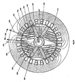
- FIG. 1 shows, in cross-section, a 2-pole machine arrangement 10 embodying the invention.
- the stator 100 has windings 101 in conventional form, wound either in a single phase or three phase configuration.
- the rotor is formed of stacked laminations. The number of such laminations determines the power output of the machine.
- the laminations are clamped together by rods (not shown in Figure 1 ) passing through the spaced holes 102 and 117, and secured at either end-most lamination, typically using end plates (not shown).
- a typical rotor diameter for a 5 to 20 kW machine is in the range 100 mm to 130 mm.
- the laminations include rotor pole pieces 107 located between the two magnetic poles.
- Each pole is formed by a pair of (embedded) permanent magnets 103, angularly spaced-apart by inter-magnet segments 106.
- the magnets 103 and rotor pole pieces 107 are mounted from a central shaft 105.
- the shaft typically is formed of non-magnetic material.
- the rotor pole pieces 107 include a series of evenly-spaced slots 109 and a central void 108.
- the void ideally would extend from a point 114 near the air gap 121 to the inner points 115 and 116 at the foot of the respective magnet, however this would compromise the structural integrity of the rotor, in which case the void 108 leaves a margin of rotor material as shown.
- the slots 109 are of various lengths to direct the flux from the magnets 103 into the air gap 121 at a desired angle normal to the rotor surface.
- the slots 109 may be varied in width and angle by modelling or experimental trial to achieve the desired lowest waveform distortion under load and the highest air gap flux.
- the slots 109 also contribute to changing the saliency of the rotor, as will be described below.
- the voids 108 and slots 109 would normally be occupied by free space, but could equally be filled with a non-magnetic material, such as aluminium.
- Saliency is the ratio of the direct axis inductance (Xd) divided by the quadrature axis inductance (Xq).
- the Xd axis lies in the direction 201 shown in Figure 2A , and Xq axis is at 90 degrees thereto.
- the magnetic flux lines 202 also are shown.
- the slots 109 are positioned in a direction 206 which bisects the angle between the Xd axis 208 (repositioned for graphical representation) and the magnetic polar (N-S) axis 207.
- Such slot orientation represents the best engineering compromise between the Xd axis and the magnets' orientation, and results in the optimum flux flow with least obstruction for the configuration in Figure 1 under both load and no load conditions.
- the length 112 and width 110 of the magnets 102 is determined by having them touch at an inner point 118 and extend to an outer point 104.
- the length 112 for an ideal 2-pole rotor should half the pole arc length, which is the radius of the rotor, but if this were the case the magnets' width 110 would be zero and there would be no room for a shaft 105. It has found that a ratio of 0.7 to the pole arc length 120 gives maximum air gap flux while allowing an adequate shaft diameter 113.
- the outer point 104 is constrained by the need to keep the magnets held in place against the centrifugal force that arises when the machine is at full speed, but should ideally extend to the full diameter of the rotor.
- the overhang at 104 on the rotor pole pieces 107 could also be removed and the magnets held in place via other methods such as gluing or bonding.
- the arc segment 111 for a 2-pole rotor preferably is 60 degrees, or one half of the arc length 119, representing an arc ratio (for a 2-pole machine) of 1/3. This split-magnet arrangement results in a significant saving in cost by reducing the volume of magnetic material needed by about 50%.
- Figure 2B shows the flux lines for the 2 pole machine 10 of Figure 1 at full electrical or mechanical load. While the Xd axis 201 lies at the centre of the flux lines at no load, the Xd axis under load 204 moves through an arc 205, resulting in flux drag caused by the torsional load on the shaft 105 and the current in the windings 101. The central voids 108 and the slots 109 ameliorate the flux drag effect. It can also be seen that the flux lines 203 from the magnet 103 have been dragged to the right. It can further be seen that the current flowing in the windings 101 is trying to drag flux from the magnet 103 to the right-hand side of the magnet. If this is allowed to happen then there will be uneven flux in the air gap 120. The number of slots included represents a compromise between increasing saliency and avoiding insufficient material forming the pole pieces that would result in saturation, leading to poor voltage regulation.
- the inter-magnet segment 106 is curved, giving a large air gap clearance 301. This is done so that the flux linkage to the stator 100 is kept to a minimum.
- the clearance 301 is restricted by the need to provide sufficient magnetic material to prevent the inter-magnet pole pieces 106 from becoming saturated.
- the inter-magnet segment 106 also locks the magnets 103 securely in place, and also keeps the magnets in close contact to the rotor pole pieces 107.
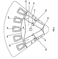
- Figure 4 shows a cut-away view of the rotor in Figure 1 where stacked laminations of rotor pole pieces 107 are held in place by bolts 401.
- the magnets 103 and segments 106 are fitted between the stacked rotor pole pieces 107, and retained by respective bolts.
- An intermediate plate 404 is provided to mechanically support the pole pieces 107.
- the bolts 401 are made from mild or high tensile steel, and are magnetic so as to allow flux to pass through them.
- the bolts 401 are anchored to a flange 406, and at the other end, a plate 402 and nuts 409 serve to both clamp the rotor pole pieces 107 together, and hold the magnets 103 and inter-magnet segments 106 to the shaft 105.
- the shaft 105 has a female taper for driving the machine when operated as a generator by an engine. This taper drive could be replaced with any suitable drive.
- a stub shaft 408 On the back end of the shaft 105 is a stub shaft 408 to take a bearing for end support.
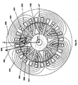
- FIG. 5 shows a 4-pole PM AC machine 50 embodying the invention.
- the machine 50 has a stator 500, windings 501, embedded permanent magnets 503 (i.e., a pair per pole), inter-magnet segments 506 and central shaft 505, as is the case with the generator shown in Figure 1 .
- fixing holes 502 are provided, as are rotor pole pieces 507.
- the correct ratio of magnet length 512 is the dimension 515, which is 1 ⁇ 2 pole segment 504. This dimensioning achieves maximum flux concentration for the minimum magnet volume.
- the reduction in magnet volume achieved by segmenting the magnet into two pieces is less than in a 2-pole rotor, at around 38%.
- the output power per volume of magnet is higher due to the higher air gap flux.
- the central void 508 has the same dimensional constraints as in Figure 1 , but has curved sides 513 to follow the required 4-pole flux lines. There are three flux control slots 509 having a curved profile, to also follow the required flux lines. A larger shaft dimension 514 than is the case for the embodiment of Figure 1 can be accommodated.
- Figure 6A shows the no-load flux lines 603 for a 4-pole embodiment of Figure 5 , where the Xd axis 601 lies in the centre of the flux lines 603.
- the curved slots 509 are orientated in the direction 606 that bisects the Xd axis 601 and the magnet polar axis 605. It can be seen that the curved sides 513 of the central void 508 and the curved slots 509 follow the flux lines 603.
- Figure 6B shows the flux lines 603 in the 4-pole rotor under full load, from which it can be seen that the effective centre of flux has moved from axis 601 to 604 by an arcuate distance 602. This exemplifies the flux drag effect for the 4-pole embodiment of Figure 5 . It can also been seen, as in Figure 6A , that current in the winding is trying to drag the flux lines 603 to the right.
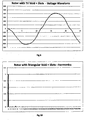
- Figure 7 shows the output voltage waveform/back emf under load for a known 2-pole embedded magnet machine without flux voids or flux control slots.
- Figure 8 is a plot of the harmonics in the waveform of Figure 7 , showing a third harmonic component of about 19.0%, and fifth harmonic of about 7.0%, with total harmonic distortion (THD) of over 20%.
- TDD total harmonic distortion
- Figure 9 shows the output voltage waveform/back emf under load for the machine shown in Figure 1 , demonstrating a near-sinusoidal shape.
- Figure 10 is a plot of the harmonics in the waveform/back emf shown in Figure 9 , indicating a third harmonic component of about 1.0%, and fifth harmonic of about 1.5%, with THD of less than 4%. Additionally, skewing the stator also reduces the THD further by 50-60% overall.
- the slots in the stator 100 containing the windings 101 can be skewed by 1 or more slots over the length of the stator to further reduce the THD. This reduces the harmonic produced by the magnets passing over the slot openings.
- the rotor can be diecast in one piece, using the diecast aluminium in the slots and void to effectively clamp the rotor segment 116 together, thus eliminating the need for the clamping bolts 401 and nuts 409.
- a secondary effect of the voids and slots in the rotor segments 107 is to improve the voltage regulation under load when operated as a generator. When operated as a motor, the voids and slots improve the torque efficiency (Nm/A) as mechanical load is increased.
- the measured voltage regulation when operated as a generator, from no load to full load was only ⁇ 3%. Also, the effect of improved THD and voltage regulation improves the efficiency of the generator.
Description
- This invention relates generally to a permanent magnet (PM) electrical machine operating either as a synchronous generator or a synchronous motor. More particularly, the invention relates to the control of harmonic components in the output/stator voltage and current waveforms under load.
- PM synchronous machines are robust, reliable and efficient, and have a relatively high energy density. They have many attractive properties compared with wound-field synchronous machines with brushed or brushless exciters. The need to save energy and increase the efficiency of motors and generators means PM synchronous machines are becoming a popular candidate because of their no-loss rotors. In some cases an energy saving of up to 20% can be achieved by using PM rotors in place of wound rotors.
- Despite these advantages, some current designs of PM synchronous machines have shortcomings. They use relatively high volumes of magnetic material that increases their cost. When operated as synchronous generators they have poor voltage regulation and can suffer from distorted voltage and current waveforms under load. When operated as synchronous motors they are difficult to start without some form of sensor feedback. Also, their (stator) back emf waveforms under load are distorted, reducing their efficiency and requiring more complex control electronics.
- These problems are greater with low pole number (e.g., 2- and 4-pole) machines, where serious waveform distortion under load commonly occurs. The distortion arises due to the so-called flux drag effect that causes the magnetic flux in the rotor to skew away from the radial axis of the magnets due to the load current in the windings. 2- and 4-pole PM generators also use more magnet material for the same power output than do higher pole number generators. Accordingly, PM synchronous generators have not found widespread use in small-scale power applications, such as single-phase and three-phase 3000 rpm (2-pole) or 1500 rpm (4-pole) petrol and diesel driven generators in the 5 to 20 kW range.
- The only practical current 2- and 4-pole designs are surface-mount magnet types. However, these also have distorted output voltage/back emf and current waveforms under load, and can suffer from demagnetization of the magnet edges under high loads. Surface-mounted magnet segments for 2-pole and 4-pole rotors have a large arc segment, meaning there is a large amount of waste material in their manufacture, increasing the monetary cost of the magnets. Current designs of surface-mount PM AC generators exhibit a large voltage drop under load. As there is no simple method of voltage regulation at constant speed for these machines, generator applications requiring good voltage regulation, cannot use PM synchronous types.
- There are, however, PM synchronous generators which have acceptable waveform and voltage regulation. These have one-piece PM rotors. The main problem with these designs is that they use up to six times or more magnet material than the equivalent surface-mount designs, even in the lower powers, and cannot be made in a 4-pole configuration. Rather, such machines are only practical in 2-pole designs up to 3 kW power rating. Above this level the magnet cost and volume increases to the square of the rotor diameter, making them no longer cost-effective.
-
US 2008/231135 A1 describes an electromagnetic steel plate forming member providing the two magnet holes for inserting therein two permanent magnets per pole along the V-shape, which are provided in the region of the radial pole pitch lines OP provided in the rotor core at the predetermined pole pitch angle theta, one magnet hole is displaced in a direction apart from the center line OC of the pole pitch lines OP, and the other magnet hole is displaced in a direction approaching to the center line OC of the pole pitch lines OP. -
US 4658165 describes a rotating machine of the type in which the rotor includes a plurality of radial permanent magnets joined by pole pieces in the form of arcs of a circle, wherein the pole pieces have slots therein which oppose the propagation of magnetic fluxes in any direction other than the substantially radial direction of the concentration of the armature flux. The result is a notable increase in the power-to-weight ratio of the machine. -
US 2011/121668 describes a rotor for rotating an electric machine having permanent magnets and flux concentration, including a shaft extending along the rotational axis of the rotor, a rotor body placed on the shaft, the rotor body having a central opening for the mounting thereof on the shaft; radially oriented recesses, wherein the permanent magnets are placed; and in at least one angular space separating two consecutive recesses, at least one cavity leading neither to the central opening nor to the two consecutive recesses, the cavity or cavities located in the space occupying an angular area around the rotational axis of the rotor greater than or equal to half of the angular area of the space. - These problems mean that current designs of PM generators and motors are suitable only for low-grade, low power applications where voltage regulation (i.e., generators) or back emf (i.e., motors), and harmonic distortion are unimportant.
- A need exists to overcome or at least ameliorate one or more of these disadvantages.
- In one broad form, there is provided an electrical synchronous machine according to
claim 1, comprising a wound stator and a rotor. The rotor includes at least two magnetic poles with each pole being formed of a pair of angularly spaced-apart permanent magnets, a rotor pole piece located between each said pole, a triangularly shaped void located in the rotor pole piece, and a plurality of slots located in the rotor pole piece. - Other aspects are disclosed.
- In the drawings:
-
Figure 1 shows a sectional view of a two-pole machine; -
Figure 2A shows the flux lines for no load for the machine ofFigure 1 ; -
Figure 2B shows the flux lines for full load for the machine ofFigure 1 ; -
Figure 3 is a partial sectional view of the machine ofFigure 1 ; -
Figure 4 shows a cut-away view of an assembled two-pole machine; -
Figure 5 shows a sectional view of a four-pole machine; -
Figure 6A shows the flux lines for no load for the machine ofFigure 5 ; -
Figure 6B shows the flux lines for full load for the machine ofFigure 5 ; -
Figure 7 shows an output voltage waveform under load for a known 2-pole machine (i.e., with no flux voids); -
Figure 8 shows a plot of the fundamental and harmonic frequency components of the output waveform ofFigure 7 ; -
Figure 9 shows an output voltage waveform under load for the two-pole machine ofFigure 1 ; and -
Figure 10 shows a plot of the fundamental and harmonic frequency components of the output waveform ofFigure 9 . - In what follows, reference to "an electrical machine" (or simply "a machine") is to be understood as applying equally to a machine configured and/or operated as a generator or motor, unless specifically indicated as being otherwise.
-
Figure 1 shows, in cross-section, a 2-pole machine arrangement 10 embodying the invention. Thestator 100 haswindings 101 in conventional form, wound either in a single phase or three phase configuration. The rotor is formed of stacked laminations. The number of such laminations determines the power output of the machine. The laminations are clamped together by rods (not shown inFigure 1 ) passing through the spacedholes range 100 mm to 130 mm. The laminations includerotor pole pieces 107 located between the two magnetic poles. Each pole is formed by a pair of (embedded)permanent magnets 103, angularly spaced-apart byinter-magnet segments 106. Themagnets 103 androtor pole pieces 107 are mounted from acentral shaft 105. The shaft typically is formed of non-magnetic material. - The
rotor pole pieces 107 include a series of evenly-spacedslots 109 and acentral void 108. The void ideally would extend from apoint 114 near theair gap 121 to theinner points void 108 leaves a margin of rotor material as shown. Theslots 109 are of various lengths to direct the flux from themagnets 103 into theair gap 121 at a desired angle normal to the rotor surface. Theslots 109 may be varied in width and angle by modelling or experimental trial to achieve the desired lowest waveform distortion under load and the highest air gap flux. Theslots 109 also contribute to changing the saliency of the rotor, as will be described below. Thevoids 108 andslots 109 would normally be occupied by free space, but could equally be filled with a non-magnetic material, such as aluminium. - Saliency is the ratio of the direct axis inductance (Xd) divided by the quadrature axis inductance (Xq). The Xd axis lies in the
direction 201 shown inFigure 2A , and Xq axis is at 90 degrees thereto. Themagnetic flux lines 202 also are shown. Theslots 109 are positioned in adirection 206 which bisects the angle between the Xd axis 208 (repositioned for graphical representation) and the magnetic polar (N-S)axis 207. Such slot orientation represents the best engineering compromise between the Xd axis and the magnets' orientation, and results in the optimum flux flow with least obstruction for the configuration inFigure 1 under both load and no load conditions. - The
length 112 andwidth 110 of themagnets 102 is determined by having them touch at aninner point 118 and extend to anouter point 104. Thelength 112 for an ideal 2-pole rotor should half the pole arc length, which is the radius of the rotor, but if this were the case the magnets'width 110 would be zero and there would be no room for ashaft 105. It has found that a ratio of 0.7 to thepole arc length 120 gives maximum air gap flux while allowing anadequate shaft diameter 113. Theouter point 104 is constrained by the need to keep the magnets held in place against the centrifugal force that arises when the machine is at full speed, but should ideally extend to the full diameter of the rotor. The overhang at 104 on therotor pole pieces 107 could also be removed and the magnets held in place via other methods such as gluing or bonding. Thearc segment 111 for a 2-pole rotor preferably is 60 degrees, or one half of thearc length 119, representing an arc ratio (for a 2-pole machine) of 1/3. This split-magnet arrangement results in a significant saving in cost by reducing the volume of magnetic material needed by about 50%. -
Figure 2B shows the flux lines for the 2pole machine 10 ofFigure 1 at full electrical or mechanical load. While theXd axis 201 lies at the centre of the flux lines at no load, the Xd axis underload 204 moves through an arc 205, resulting in flux drag caused by the torsional load on theshaft 105 and the current in thewindings 101. Thecentral voids 108 and theslots 109 ameliorate the flux drag effect. It can also be seen that theflux lines 203 from themagnet 103 have been dragged to the right. It can further be seen that the current flowing in thewindings 101 is trying to drag flux from themagnet 103 to the right-hand side of the magnet. If this is allowed to happen then there will be uneven flux in theair gap 120. The number of slots included represents a compromise between increasing saliency and avoiding insufficient material forming the pole pieces that would result in saturation, leading to poor voltage regulation. - Referring now to
Figure 3 , it can be seen that theinter-magnet segment 106 is curved, giving a largeair gap clearance 301. This is done so that the flux linkage to thestator 100 is kept to a minimum. Theclearance 301 is restricted by the need to provide sufficient magnetic material to prevent theinter-magnet pole pieces 106 from becoming saturated. Theinter-magnet segment 106 also locks themagnets 103 securely in place, and also keeps the magnets in close contact to therotor pole pieces 107. -
Figure 4 shows a cut-away view of the rotor inFigure 1 where stacked laminations ofrotor pole pieces 107 are held in place bybolts 401. Themagnets 103 andsegments 106 are fitted between the stackedrotor pole pieces 107, and retained by respective bolts. Anintermediate plate 404 is provided to mechanically support thepole pieces 107. Thebolts 401 are made from mild or high tensile steel, and are magnetic so as to allow flux to pass through them. Thebolts 401 are anchored to aflange 406, and at the other end, aplate 402 andnuts 409 serve to both clamp therotor pole pieces 107 together, and hold themagnets 103 andinter-magnet segments 106 to theshaft 105. For ease of assembly, the magnets of a longer rotor are also split into segments 103' lengthwise. Theshaft 105 has a female taper for driving the machine when operated as a generator by an engine. This taper drive could be replaced with any suitable drive. On the back end of theshaft 105 is astub shaft 408 to take a bearing for end support. -
Figure 5 shows a 4-polePM AC machine 50 embodying the invention. Themachine 50 has astator 500,windings 501, embedded permanent magnets 503 (i.e., a pair per pole),inter-magnet segments 506 andcentral shaft 505, as is the case with the generator shown inFigure 1 . In the same way, fixingholes 502 are provided, as arerotor pole pieces 507. In this 4-pole rotor arrangement, the correct ratio ofmagnet length 512 is thedimension 515, which is ½pole segment 504. This dimensioning achieves maximum flux concentration for the minimum magnet volume. The reduction in magnet volume achieved by segmenting the magnet into two pieces is less than in a 2-pole rotor, at around 38%. However, the output power per volume of magnet is higher due to the higher air gap flux. This is because the ideal magnet-to-pole arc ratio can be achieved in 4-pole designs. Thecentral void 508 has the same dimensional constraints as inFigure 1 , but hascurved sides 513 to follow the required 4-pole flux lines. There are threeflux control slots 509 having a curved profile, to also follow the required flux lines. A larger shaft dimension 514 than is the case for the embodiment ofFigure 1 can be accommodated. -
Figure 6A shows the no-load flux lines 603 for a 4-pole embodiment ofFigure 5 , where theXd axis 601 lies in the centre of the flux lines 603. Similarly to the 2-pole configuration, thecurved slots 509 are orientated in thedirection 606 that bisects theXd axis 601 and the magnetpolar axis 605. It can be seen that thecurved sides 513 of thecentral void 508 and thecurved slots 509 follow the flux lines 603. -
Figure 6B shows theflux lines 603 in the 4-pole rotor under full load, from which it can be seen that the effective centre of flux has moved fromaxis 601 to 604 by anarcuate distance 602. This exemplifies the flux drag effect for the 4-pole embodiment ofFigure 5 . It can also been seen, as inFigure 6A , that current in the winding is trying to drag theflux lines 603 to the right. -
Figure 7 shows the output voltage waveform/back emf under load for a known 2-pole embedded magnet machine without flux voids or flux control slots.Figure 8 is a plot of the harmonics in the waveform ofFigure 7 , showing a third harmonic component of about 19.0%, and fifth harmonic of about 7.0%, with total harmonic distortion (THD) of over 20%. -
Figure 9 shows the output voltage waveform/back emf under load for the machine shown inFigure 1 , demonstrating a near-sinusoidal shape.Figure 10 is a plot of the harmonics in the waveform/back emf shown inFigure 9 , indicating a third harmonic component of about 1.0%, and fifth harmonic of about 1.5%, with THD of less than 4%. Additionally, skewing the stator also reduces the THD further by 50-60% overall. - In other embodiments, the slots in the
stator 100 containing thewindings 101 can be skewed by 1 or more slots over the length of the stator to further reduce the THD. This reduces the harmonic produced by the magnets passing over the slot openings. The rotor can be diecast in one piece, using the diecast aluminium in the slots and void to effectively clamp therotor segment 116 together, thus eliminating the need for the clampingbolts 401 and nuts 409. A secondary effect of the voids and slots in therotor segments 107 is to improve the voltage regulation under load when operated as a generator. When operated as a motor, the voids and slots improve the torque efficiency (Nm/A) as mechanical load is increased. - In the embodiments shown, the measured voltage regulation, when operated as a generator, from no load to full load was only ± 3%. Also, the effect of improved THD and voltage regulation improves the efficiency of the generator.
- When operated as a motor, a 20% improvement in torque delivered for the same current at full load was observed compared with the known 2-pole machine. Additionally, since the back emf exhibits a good sine wave, high efficiency is achieved over the full load range. Furthermore, the back emf changes as the load torque forces the flux from the centre point, and this drop in back emf results in an increased current, meaning no feedback is required to a variable frequency supply with changing loads (i.e., providing full sensor-less control). Since the machine design exhibits a non-linear torque/back emf relationship, a resultant large angle exists over which the rotor can produce effective torque, making low pole number motors easier to start.
- The foregoing describes only some embodiments of the present invention, and modifications and/or changes can be made thereto without departing from the scope of the invention as claimed, the embodiments being illustrative and not restrictive.
Claims (7)
- A permanent magnet rotating electrical machine (10) comprising:a wound stator (100); anda round rotor including at least two magnetic poles,characterized in that each pole is formed of a pair of angularly spaced-apart permanent magnets (103) with unlike magnetic poles of the pair of angularly spaced-apart permanent magnets (103) facing each other, a rotor pole piece (107) located between each said pole, a triangularly shaped void (108) located in the middle of the rotor pole piece (107), and a plurality of elongate slots (109) located in the rotor pole piece (107) between the void (108) and an adjacent magnet (103), and wherein the slots (109) are oriented in the rotor pole piece (107) to bisect the angle between the no-load direct axis inductance (208) and the magnetic polar axis (207).
- The machine of claim 1, wherein the voids and slots are dimensioned and located such that the relative total harmonic distortion of the output voltage waveform under load is less than 5%.
- The machine of claim 1, wherein there are two poles and four slots between a void and an adjacent magnet.
- The machine of claim 1, wherein there are four poles and three slots between a void and an adjacent magnet.
- The machine of any one of the preceding claims, further including a triangularly shaped spacer located between the magnets of each pole.
- The machine of any one of the preceding claims configured as a generator.
- The machine of any one of the preceding claims configured as a motor.
Applications Claiming Priority (3)
| Application Number | Priority Date | Filing Date | Title |
|---|---|---|---|
| AU2011903974A AU2011903974A0 (en) | 2011-09-26 | Permanent magnet electrical generators | |
| AU2012902715A AU2012902715A0 (en) | 2012-06-26 | Permanent magnet electrical machine | |
| PCT/AU2012/001131 WO2013044293A1 (en) | 2011-09-26 | 2012-09-20 | Permanent magnet electrical machine |
Publications (3)
| Publication Number | Publication Date |
|---|---|
| EP2761725A1 EP2761725A1 (en) | 2014-08-06 |
| EP2761725A4 EP2761725A4 (en) | 2015-09-30 |
| EP2761725B1 true EP2761725B1 (en) | 2019-05-29 |
Family
ID=47971488
Family Applications (1)
| Application Number | Title | Priority Date | Filing Date |
|---|---|---|---|
| EP12835893.4A Active EP2761725B1 (en) | 2011-09-26 | 2012-09-20 | Permanent magnet electrical machine |
Country Status (8)
| Country | Link |
|---|---|
| US (1) | US9461510B2 (en) |
| EP (1) | EP2761725B1 (en) |
| JP (1) | JP6042893B2 (en) |
| KR (1) | KR101941324B1 (en) |
| CN (1) | CN103023256B (en) |
| AU (1) | AU2013202118B2 (en) |
| CA (1) | CA2872899C (en) |
| WO (1) | WO2013044293A1 (en) |
Families Citing this family (13)
| Publication number | Priority date | Publication date | Assignee | Title |
|---|---|---|---|---|
| CN103023255A (en) * | 2011-09-26 | 2013-04-03 | 辐射通量实验室私人有限公司 | Electromagnetic machine |
| EP2983273B1 (en) * | 2013-04-01 | 2019-12-18 | Fuji Electric Co., Ltd. | Rotating electrical machine with embedded permanent magnet |
| FR3019948B1 (en) * | 2014-04-10 | 2017-12-22 | Moteurs Leroy-Somer | ROTOR OF ELECTRIC ROTATING MACHINE. |
| FR3019949B1 (en) * | 2014-04-10 | 2018-01-05 | Moteurs Leroy-Somer | ROTOR OF ELECTRIC ROTATING MACHINE. |
| US10749391B2 (en) * | 2017-03-06 | 2020-08-18 | Ford Global Technologies, Llc | Electric machine rotor |
| US10355537B2 (en) | 2017-03-27 | 2019-07-16 | Ford Global Technologies, Llc | Method for adjusting magnetic permeability of electrical steel |
| KR102390035B1 (en) * | 2017-06-21 | 2022-04-25 | 엘지전자 주식회사 | Flux Concentrate Type Motor |
| CN108336842B (en) * | 2018-03-16 | 2020-10-16 | 珠海格力节能环保制冷技术研究中心有限公司 | Rotor structure, permanent magnet auxiliary synchronous reluctance motor and electric automobile |
| CN108566005B (en) * | 2018-03-16 | 2020-10-30 | 珠海格力节能环保制冷技术研究中心有限公司 | Rotor structure, permanent magnet auxiliary synchronous reluctance motor and electric automobile |
| CN108336844B (en) * | 2018-03-16 | 2020-10-23 | 珠海格力节能环保制冷技术研究中心有限公司 | Rotor structure, permanent magnet auxiliary synchronous reluctance motor and electric automobile |
| US20200083767A1 (en) * | 2018-09-06 | 2020-03-12 | Adlee Powertronic Co., Ltd. | Permanent magnet motor |
| US11581767B2 (en) | 2018-09-06 | 2023-02-14 | Adlee Powertronic Co., Ltd. | Permanent magnet motor |
| CN112165195B (en) * | 2020-09-30 | 2022-02-11 | 安徽美芝精密制造有限公司 | Motor and compressor |
Family Cites Families (37)
| Publication number | Priority date | Publication date | Assignee | Title |
|---|---|---|---|---|
| GB191015587A (en) | 1910-06-29 | 1911-09-29 | Richard Ambrose Holbech | Improvements in or relating to Dynamo-electric Machinery. |
| US2483848A (en) | 1946-12-14 | 1949-10-04 | Holtzer Cabot Inc | Synchronous motor |
| US3210584A (en) | 1961-04-20 | 1965-10-05 | Allis Louis Co | Synchronous induction machine |
| US3243620A (en) | 1963-05-01 | 1966-03-29 | Gen Electric | Synchronous induction motors having an improved rotor construction |
| FR1515055A (en) | 1966-11-23 | 1968-03-01 | Ragonot Ets | Reluctance motor rotor |
| US3597646A (en) | 1970-01-26 | 1971-08-03 | Peter John Lawrenson | Dynamoelectric machines |
| US3652885A (en) | 1970-09-16 | 1972-03-28 | Allis Chalmers Mfg Co | Synchronous reluctance motor |
| US3721844A (en) | 1971-05-27 | 1973-03-20 | Nat Res Dev | Reluctance motors |
| GB1448990A (en) | 1972-12-22 | 1976-09-08 | Nat Res Dev | Roatary and linear electric machines |
| FR2548843B1 (en) * | 1983-07-07 | 1986-11-07 | Labinal | IMPROVEMENT IN ROTARY MAGNET ROTOR MACHINES |
| JPS6026444A (en) | 1983-07-20 | 1985-02-09 | Hitachi Ltd | Ac generator for automobile |
| US4568846A (en) | 1983-10-28 | 1986-02-04 | Welco Industries | Permanent magnet laminated rotor with conductor bars |
| US4703243A (en) * | 1986-04-17 | 1987-10-27 | Kollmorgen Technologies Corporation | Stepping motor harmonic suppression |
| US5508576A (en) * | 1990-07-12 | 1996-04-16 | Seiko Epson Corporation | Rotor for brushless electromotor |
| DE69206620D1 (en) * | 1991-07-04 | 1996-01-18 | Acm Azienda Cost Motori | DRIVE DEVICE FOR THE CYLINDER OF A STOCKING KNITTING MACHINE AND ROTOR FOR A BRUSHLESS SYNCHRONOUS MOTOR. |
| JPH06319238A (en) * | 1991-09-10 | 1994-11-15 | Advance Koojienereeshiyon Syst Gijutsu Kenkyu Kumiai | Rotor for permanent magnet generator |
| JP3425176B2 (en) * | 1993-02-10 | 2003-07-07 | 本田技研工業株式会社 | Motor or generator yoke |
| US5296773A (en) | 1993-04-20 | 1994-03-22 | General Motors Corporation | Composite rotor for a synchronous reluctance machine |
| IT1268427B1 (en) | 1993-10-21 | 1997-03-04 | Giorgio Gurrieri | HIGH PERFORMANCE SALENT POLES RELUCTANCE SYNCHRONOUS MOTOR EQUIPPED WITH SHORT-CIRCUIT CAGE |
| EP0678967A1 (en) | 1994-04-18 | 1995-10-25 | General Electric Company | Rotor for permanent magnet motor |
| JPH08242567A (en) * | 1995-03-02 | 1996-09-17 | Daido Steel Co Ltd | Synchronous motor |
| IT1276487B1 (en) | 1995-07-11 | 1997-10-31 | Alfredo Vagati | SYNCHRONOUS RELUCTANCE ELECTRIC MOTOR WITH LOW TORQUE WAVING |
| US5831367A (en) | 1997-02-13 | 1998-11-03 | Emerson Electric Co. | Line-start reluctance motor with grain-oriented rotor laminations |
| US6815859B2 (en) | 2001-03-07 | 2004-11-09 | Aisin Seiki Kabushiki Kaisha | Synchronous reluctance motor |
| US6891298B2 (en) * | 2002-08-28 | 2005-05-10 | Emerson Electric Co. | Interior permanent magnet machine with reduced magnet chattering |
| CN1726629B (en) | 2002-12-12 | 2010-11-03 | Lg电子株式会社 | Rotor for line-start reluctance motor |
| JP2004222356A (en) * | 2003-01-10 | 2004-08-05 | Moric Co Ltd | Rotating electric equipment |
| JP4449035B2 (en) * | 2004-03-10 | 2010-04-14 | 日立オートモティブシステムズ株式会社 | Permanent magnet rotating electric machine for electric vehicles |
| KR20080063747A (en) | 2005-08-12 | 2008-07-07 | 파워 그룹 인터내셔널 인코포레이티드 | Self-regulated permanent magnet generator |
| US7301310B2 (en) | 2005-08-24 | 2007-11-27 | Honeywell International, Inc. | Excitation controlled synchronous permanent magnet machine |
| CN101529698B (en) | 2007-02-26 | 2011-09-21 | 三菱电机株式会社 | Permanent magnet motor, hermetic compressor, and fan motor |
| JP4404223B2 (en) * | 2007-03-20 | 2010-01-27 | 株式会社安川電機 | Electromagnetic steel sheet forming body, electromagnetic steel sheet laminate, permanent magnet type synchronous rotating electric machine equipped with the same, permanent magnet type synchronous rotating electric machine, vehicle using the rotating electric machine, elevator, fluid machine, processing machine |
| WO2008137709A2 (en) * | 2007-05-04 | 2008-11-13 | A. O. Smith Corporation | Interior permanent magnet motor and rotor |
| FR2932618B1 (en) | 2008-06-16 | 2010-11-19 | Leroy Somer Moteurs | ROTOR WITH PERMANENT MAGNETS AND ROTATING MACHINE COMPRISING SUCH A ROTOR |
| US8102091B2 (en) * | 2008-07-30 | 2012-01-24 | Regal Beloit Epc Inc. | Interior permanent magnet motor including rotor with unequal poles |
| JP5589345B2 (en) * | 2009-10-21 | 2014-09-17 | 富士電機株式会社 | Permanent magnet rotating electric machine |
| FR2958466B1 (en) | 2010-03-31 | 2017-09-08 | Valeo Equip Electr Moteur | SYNCHRONOUS ROTATING ELECTRIC MACHINE WITH PERMANENT MAGNETS AND FLOW CONCENTRATION |
-
2012
- 2012-08-17 CN CN201210296028.5A patent/CN103023256B/en active Active
- 2012-09-20 JP JP2014531046A patent/JP6042893B2/en active Active
- 2012-09-20 EP EP12835893.4A patent/EP2761725B1/en active Active
- 2012-09-20 US US14/347,233 patent/US9461510B2/en active Active
- 2012-09-20 CA CA2872899A patent/CA2872899C/en active Active
- 2012-09-20 AU AU2013202118A patent/AU2013202118B2/en active Active
- 2012-09-20 WO PCT/AU2012/001131 patent/WO2013044293A1/en active Application Filing
- 2012-09-20 KR KR1020147007921A patent/KR101941324B1/en active IP Right Grant
Non-Patent Citations (1)
| Title |
|---|
| None * |
Also Published As
| Publication number | Publication date |
|---|---|
| AU2013202118A1 (en) | 2013-05-02 |
| CA2872899A1 (en) | 2013-04-04 |
| AU2013202118B2 (en) | 2014-10-30 |
| JP2014526875A (en) | 2014-10-06 |
| KR101941324B1 (en) | 2019-01-22 |
| CN103023256B (en) | 2017-03-01 |
| EP2761725A1 (en) | 2014-08-06 |
| CA2872899C (en) | 2019-04-02 |
| EP2761725A4 (en) | 2015-09-30 |
| CN103023256A (en) | 2013-04-03 |
| US9461510B2 (en) | 2016-10-04 |
| JP6042893B2 (en) | 2016-12-14 |
| WO2013044293A1 (en) | 2013-04-04 |
| US20140246938A1 (en) | 2014-09-04 |
| KR20140067068A (en) | 2014-06-03 |
Similar Documents
| Publication | Publication Date | Title |
|---|---|---|
| EP2761725B1 (en) | Permanent magnet electrical machine | |
| Li et al. | Analysis of fractional-slot concentrated winding PM vernier machines with regular open-slot stators | |
| US7514833B2 (en) | Axial gap permanent-magnet machine with reluctance poles and PM element covers | |
| AU2011313817B2 (en) | Electromagnetic machine | |
| US7932658B2 (en) | Interior permanent magnet motor including rotor with flux barriers | |
| US8102091B2 (en) | Interior permanent magnet motor including rotor with unequal poles | |
| US8294322B2 (en) | Rotating electrical machine | |
| JP5260563B2 (en) | Permanent magnet generator or motor | |
| US7902700B1 (en) | Low harmonic loss brushless motor | |
| KR20110128311A (en) | Electric machine | |
| CN101651371B (en) | Stator surface mounted doubly salient permanent magnet motor with auxiliary salient pole | |
| WO2007048211A2 (en) | Permanent magnet rotor | |
| JP2013236534A (en) | Rotary electric machine | |
| CN110838779B (en) | Mixed excitation wound rotor and mixed excitation wound synchronous motor | |
| GB2454171A (en) | Reluctance machines or the inductor type with permanent magnets integrated into the stator | |
| CN110943557A (en) | Halbach array permanent magnet synchronous motor | |
| KR101209631B1 (en) | Rotor having different length and LSPM(Line-Start Permanent Magnet) motor comprising the rotor | |
| CN208675081U (en) | A kind of magnetic pawl motor of high power density high efficiency high reliability | |
| CN103023255A (en) | Electromagnetic machine | |
| CN209375272U (en) | A kind of Double-stator motor of ectonexine permanent magnet dislocation | |
| CN214281054U (en) | Inner rotor permanent magnet motor with low-torque-ripple split stator structure | |
| CN219477687U (en) | Monopole motor with unequally-spaced auxiliary tooth structure | |
| KR101209623B1 (en) | Rotor and LSPM(Line-Start Permanent Magnet) motor having the rotor | |
| CN115224843A (en) | Hybrid excitation axial magnetic field asymmetric air gap hybrid excitation spoke type permanent magnet motor | |
| JP2008048584A (en) | Synchronous reluctance generator |
Legal Events
| Date | Code | Title | Description |
|---|---|---|---|
| PUAI | Public reference made under article 153(3) epc to a published international application that has entered the european phase |
Free format text: ORIGINAL CODE: 0009012 |
|
| 17P | Request for examination filed |
Effective date: 20140428 |
|
| AK | Designated contracting states |
Kind code of ref document: A1 Designated state(s): AL AT BE BG CH CY CZ DE DK EE ES FI FR GB GR HR HU IE IS IT LI LT LU LV MC MK MT NL NO PL PT RO RS SE SI SK SM TR |
|
| DAX | Request for extension of the european patent (deleted) | ||
| RA4 | Supplementary search report drawn up and despatched (corrected) |
Effective date: 20150831 |
|
| RIC1 | Information provided on ipc code assigned before grant |
Ipc: H02K 1/28 20060101ALI20150825BHEP Ipc: H02K 1/27 20060101AFI20150825BHEP |
|
| 17Q | First examination report despatched |
Effective date: 20160713 |
|
| STAA | Information on the status of an ep patent application or granted ep patent |
Free format text: STATUS: EXAMINATION IS IN PROGRESS |
|
| GRAP | Despatch of communication of intention to grant a patent |
Free format text: ORIGINAL CODE: EPIDOSNIGR1 |
|
| STAA | Information on the status of an ep patent application or granted ep patent |
Free format text: STATUS: GRANT OF PATENT IS INTENDED |
|
| INTG | Intention to grant announced |
Effective date: 20190204 |
|
| GRAS | Grant fee paid |
Free format text: ORIGINAL CODE: EPIDOSNIGR3 |
|
| GRAA | (expected) grant |
Free format text: ORIGINAL CODE: 0009210 |
|
| STAA | Information on the status of an ep patent application or granted ep patent |
Free format text: STATUS: THE PATENT HAS BEEN GRANTED |
|
| AK | Designated contracting states |
Kind code of ref document: B1 Designated state(s): AL AT BE BG CH CY CZ DE DK EE ES FI FR GB GR HR HU IE IS IT LI LT LU LV MC MK MT NL NO PL PT RO RS SE SI SK SM TR |
|
| REG | Reference to a national code |
Ref country code: GB Ref legal event code: FG4D |
|
| REG | Reference to a national code |
Ref country code: CH Ref legal event code: EP |
|
| REG | Reference to a national code |
Ref country code: AT Ref legal event code: REF Ref document number: 1138843 Country of ref document: AT Kind code of ref document: T Effective date: 20190615 |
|
| REG | Reference to a national code |
Ref country code: DE Ref legal event code: R096 Ref document number: 602012060621 Country of ref document: DE |
|
| REG | Reference to a national code |
Ref country code: IE Ref legal event code: FG4D |
|
| REG | Reference to a national code |
Ref country code: NL Ref legal event code: MP Effective date: 20190529 |
|
| REG | Reference to a national code |
Ref country code: LT Ref legal event code: MG4D |
|
| PG25 | Lapsed in a contracting state [announced via postgrant information from national office to epo] |
Ref country code: LT Free format text: LAPSE BECAUSE OF FAILURE TO SUBMIT A TRANSLATION OF THE DESCRIPTION OR TO PAY THE FEE WITHIN THE PRESCRIBED TIME-LIMIT Effective date: 20190529 Ref country code: HR Free format text: LAPSE BECAUSE OF FAILURE TO SUBMIT A TRANSLATION OF THE DESCRIPTION OR TO PAY THE FEE WITHIN THE PRESCRIBED TIME-LIMIT Effective date: 20190529 Ref country code: SE Free format text: LAPSE BECAUSE OF FAILURE TO SUBMIT A TRANSLATION OF THE DESCRIPTION OR TO PAY THE FEE WITHIN THE PRESCRIBED TIME-LIMIT Effective date: 20190529 Ref country code: FI Free format text: LAPSE BECAUSE OF FAILURE TO SUBMIT A TRANSLATION OF THE DESCRIPTION OR TO PAY THE FEE WITHIN THE PRESCRIBED TIME-LIMIT Effective date: 20190529 Ref country code: NO Free format text: LAPSE BECAUSE OF FAILURE TO SUBMIT A TRANSLATION OF THE DESCRIPTION OR TO PAY THE FEE WITHIN THE PRESCRIBED TIME-LIMIT Effective date: 20190829 Ref country code: AL Free format text: LAPSE BECAUSE OF FAILURE TO SUBMIT A TRANSLATION OF THE DESCRIPTION OR TO PAY THE FEE WITHIN THE PRESCRIBED TIME-LIMIT Effective date: 20190529 Ref country code: ES Free format text: LAPSE BECAUSE OF FAILURE TO SUBMIT A TRANSLATION OF THE DESCRIPTION OR TO PAY THE FEE WITHIN THE PRESCRIBED TIME-LIMIT Effective date: 20190529 Ref country code: PT Free format text: LAPSE BECAUSE OF FAILURE TO SUBMIT A TRANSLATION OF THE DESCRIPTION OR TO PAY THE FEE WITHIN THE PRESCRIBED TIME-LIMIT Effective date: 20190930 |
|
| PG25 | Lapsed in a contracting state [announced via postgrant information from national office to epo] |
Ref country code: BG Free format text: LAPSE BECAUSE OF FAILURE TO SUBMIT A TRANSLATION OF THE DESCRIPTION OR TO PAY THE FEE WITHIN THE PRESCRIBED TIME-LIMIT Effective date: 20190829 Ref country code: GR Free format text: LAPSE BECAUSE OF FAILURE TO SUBMIT A TRANSLATION OF THE DESCRIPTION OR TO PAY THE FEE WITHIN THE PRESCRIBED TIME-LIMIT Effective date: 20190830 Ref country code: RS Free format text: LAPSE BECAUSE OF FAILURE TO SUBMIT A TRANSLATION OF THE DESCRIPTION OR TO PAY THE FEE WITHIN THE PRESCRIBED TIME-LIMIT Effective date: 20190529 Ref country code: LV Free format text: LAPSE BECAUSE OF FAILURE TO SUBMIT A TRANSLATION OF THE DESCRIPTION OR TO PAY THE FEE WITHIN THE PRESCRIBED TIME-LIMIT Effective date: 20190529 |
|
| REG | Reference to a national code |
Ref country code: AT Ref legal event code: MK05 Ref document number: 1138843 Country of ref document: AT Kind code of ref document: T Effective date: 20190529 |
|
| PG25 | Lapsed in a contracting state [announced via postgrant information from national office to epo] |
Ref country code: RO Free format text: LAPSE BECAUSE OF FAILURE TO SUBMIT A TRANSLATION OF THE DESCRIPTION OR TO PAY THE FEE WITHIN THE PRESCRIBED TIME-LIMIT Effective date: 20190529 Ref country code: SK Free format text: LAPSE BECAUSE OF FAILURE TO SUBMIT A TRANSLATION OF THE DESCRIPTION OR TO PAY THE FEE WITHIN THE PRESCRIBED TIME-LIMIT Effective date: 20190529 Ref country code: EE Free format text: LAPSE BECAUSE OF FAILURE TO SUBMIT A TRANSLATION OF THE DESCRIPTION OR TO PAY THE FEE WITHIN THE PRESCRIBED TIME-LIMIT Effective date: 20190529 Ref country code: AT Free format text: LAPSE BECAUSE OF FAILURE TO SUBMIT A TRANSLATION OF THE DESCRIPTION OR TO PAY THE FEE WITHIN THE PRESCRIBED TIME-LIMIT Effective date: 20190529 Ref country code: DK Free format text: LAPSE BECAUSE OF FAILURE TO SUBMIT A TRANSLATION OF THE DESCRIPTION OR TO PAY THE FEE WITHIN THE PRESCRIBED TIME-LIMIT Effective date: 20190529 Ref country code: CZ Free format text: LAPSE BECAUSE OF FAILURE TO SUBMIT A TRANSLATION OF THE DESCRIPTION OR TO PAY THE FEE WITHIN THE PRESCRIBED TIME-LIMIT Effective date: 20190529 Ref country code: NL Free format text: LAPSE BECAUSE OF FAILURE TO SUBMIT A TRANSLATION OF THE DESCRIPTION OR TO PAY THE FEE WITHIN THE PRESCRIBED TIME-LIMIT Effective date: 20190529 |
|
| PG25 | Lapsed in a contracting state [announced via postgrant information from national office to epo] |
Ref country code: SM Free format text: LAPSE BECAUSE OF FAILURE TO SUBMIT A TRANSLATION OF THE DESCRIPTION OR TO PAY THE FEE WITHIN THE PRESCRIBED TIME-LIMIT Effective date: 20190529 |
|
| REG | Reference to a national code |
Ref country code: DE Ref legal event code: R097 Ref document number: 602012060621 Country of ref document: DE |
|
| PG25 | Lapsed in a contracting state [announced via postgrant information from national office to epo] |
Ref country code: TR Free format text: LAPSE BECAUSE OF FAILURE TO SUBMIT A TRANSLATION OF THE DESCRIPTION OR TO PAY THE FEE WITHIN THE PRESCRIBED TIME-LIMIT Effective date: 20190529 |
|
| PLBE | No opposition filed within time limit |
Free format text: ORIGINAL CODE: 0009261 |
|
| STAA | Information on the status of an ep patent application or granted ep patent |
Free format text: STATUS: NO OPPOSITION FILED WITHIN TIME LIMIT |
|
| PG25 | Lapsed in a contracting state [announced via postgrant information from national office to epo] |
Ref country code: PL Free format text: LAPSE BECAUSE OF FAILURE TO SUBMIT A TRANSLATION OF THE DESCRIPTION OR TO PAY THE FEE WITHIN THE PRESCRIBED TIME-LIMIT Effective date: 20190529 |
|
| 26N | No opposition filed |
Effective date: 20200303 |
|
| PG25 | Lapsed in a contracting state [announced via postgrant information from national office to epo] |
Ref country code: SI Free format text: LAPSE BECAUSE OF FAILURE TO SUBMIT A TRANSLATION OF THE DESCRIPTION OR TO PAY THE FEE WITHIN THE PRESCRIBED TIME-LIMIT Effective date: 20190529 Ref country code: MC Free format text: LAPSE BECAUSE OF FAILURE TO SUBMIT A TRANSLATION OF THE DESCRIPTION OR TO PAY THE FEE WITHIN THE PRESCRIBED TIME-LIMIT Effective date: 20190529 |
|
| REG | Reference to a national code |
Ref country code: CH Ref legal event code: PL |
|
| PG25 | Lapsed in a contracting state [announced via postgrant information from national office to epo] |
Ref country code: LU Free format text: LAPSE BECAUSE OF NON-PAYMENT OF DUE FEES Effective date: 20190920 Ref country code: CH Free format text: LAPSE BECAUSE OF NON-PAYMENT OF DUE FEES Effective date: 20190930 Ref country code: LI Free format text: LAPSE BECAUSE OF NON-PAYMENT OF DUE FEES Effective date: 20190930 Ref country code: IE Free format text: LAPSE BECAUSE OF NON-PAYMENT OF DUE FEES Effective date: 20190920 |
|
| REG | Reference to a national code |
Ref country code: BE Ref legal event code: MM Effective date: 20190930 |
|
| PG25 | Lapsed in a contracting state [announced via postgrant information from national office to epo] |
Ref country code: BE Free format text: LAPSE BECAUSE OF NON-PAYMENT OF DUE FEES Effective date: 20190930 |
|
| GBPC | Gb: european patent ceased through non-payment of renewal fee |
Effective date: 20190920 |
|
| PG25 | Lapsed in a contracting state [announced via postgrant information from national office to epo] |
Ref country code: GB Free format text: LAPSE BECAUSE OF NON-PAYMENT OF DUE FEES Effective date: 20190920 |
|
| PG25 | Lapsed in a contracting state [announced via postgrant information from national office to epo] |
Ref country code: CY Free format text: LAPSE BECAUSE OF FAILURE TO SUBMIT A TRANSLATION OF THE DESCRIPTION OR TO PAY THE FEE WITHIN THE PRESCRIBED TIME-LIMIT Effective date: 20190529 |
|
| PG25 | Lapsed in a contracting state [announced via postgrant information from national office to epo] |
Ref country code: IS Free format text: LAPSE BECAUSE OF FAILURE TO SUBMIT A TRANSLATION OF THE DESCRIPTION OR TO PAY THE FEE WITHIN THE PRESCRIBED TIME-LIMIT Effective date: 20190929 |
|
| PG25 | Lapsed in a contracting state [announced via postgrant information from national office to epo] |
Ref country code: MT Free format text: LAPSE BECAUSE OF FAILURE TO SUBMIT A TRANSLATION OF THE DESCRIPTION OR TO PAY THE FEE WITHIN THE PRESCRIBED TIME-LIMIT Effective date: 20190529 Ref country code: HU Free format text: LAPSE BECAUSE OF FAILURE TO SUBMIT A TRANSLATION OF THE DESCRIPTION OR TO PAY THE FEE WITHIN THE PRESCRIBED TIME-LIMIT; INVALID AB INITIO Effective date: 20120920 |
|
| PG25 | Lapsed in a contracting state [announced via postgrant information from national office to epo] |
Ref country code: MK Free format text: LAPSE BECAUSE OF FAILURE TO SUBMIT A TRANSLATION OF THE DESCRIPTION OR TO PAY THE FEE WITHIN THE PRESCRIBED TIME-LIMIT Effective date: 20190529 |
|
| PGFP | Annual fee paid to national office [announced via postgrant information from national office to epo] |
Ref country code: FR Payment date: 20220920 Year of fee payment: 11 |
|
| PGFP | Annual fee paid to national office [announced via postgrant information from national office to epo] |
Ref country code: DE Payment date: 20230919 Year of fee payment: 12 |
|
| PGFP | Annual fee paid to national office [announced via postgrant information from national office to epo] |
Ref country code: IT Payment date: 20230922 Year of fee payment: 12 |