EP2761263B1 - Système et procédé de détection à réseau de diffraction à fibre optique - Google Patents
Système et procédé de détection à réseau de diffraction à fibre optique Download PDFInfo
- Publication number
- EP2761263B1 EP2761263B1 EP12762530.9A EP12762530A EP2761263B1 EP 2761263 B1 EP2761263 B1 EP 2761263B1 EP 12762530 A EP12762530 A EP 12762530A EP 2761263 B1 EP2761263 B1 EP 2761263B1
- Authority
- EP
- European Patent Office
- Prior art keywords
- wavelength
- wavelengths
- range
- gratings
- grating
- Prior art date
- Legal status (The legal status is an assumption and is not a legal conclusion. Google has not performed a legal analysis and makes no representation as to the accuracy of the status listed.)
- Not-in-force
Links
- 239000013307 optical fiber Substances 0.000 title claims description 65
- 238000000034 method Methods 0.000 title claims description 25
- 238000005259 measurement Methods 0.000 claims description 35
- 239000000835 fiber Substances 0.000 claims description 30
- 230000003287 optical effect Effects 0.000 claims description 8
- 238000004590 computer program Methods 0.000 claims description 2
- 238000004364 calculation method Methods 0.000 description 9
- 230000008859 change Effects 0.000 description 8
- 208000003173 lipoprotein glomerulopathy Diseases 0.000 description 3
- 238000004458 analytical method Methods 0.000 description 2
- 238000005253 cladding Methods 0.000 description 2
- 230000008878 coupling Effects 0.000 description 2
- 238000010168 coupling process Methods 0.000 description 2
- 238000005859 coupling reaction Methods 0.000 description 2
- 238000012544 monitoring process Methods 0.000 description 2
- 230000008569 process Effects 0.000 description 2
- 230000009467 reduction Effects 0.000 description 2
- 238000010521 absorption reaction Methods 0.000 description 1
- 238000009825 accumulation Methods 0.000 description 1
- 238000009529 body temperature measurement Methods 0.000 description 1
- 230000015556 catabolic process Effects 0.000 description 1
- 239000002131 composite material Substances 0.000 description 1
- 230000001419 dependent effect Effects 0.000 description 1
- 238000001514 detection method Methods 0.000 description 1
- 230000003292 diminished effect Effects 0.000 description 1
- 230000000694 effects Effects 0.000 description 1
- 230000005611 electricity Effects 0.000 description 1
- 230000007613 environmental effect Effects 0.000 description 1
- 238000002474 experimental method Methods 0.000 description 1
- 229910052736 halogen Inorganic materials 0.000 description 1
- 150000002367 halogens Chemical class 0.000 description 1
- 230000001771 impaired effect Effects 0.000 description 1
- 230000001939 inductive effect Effects 0.000 description 1
- 238000007689 inspection Methods 0.000 description 1
- 238000009434 installation Methods 0.000 description 1
- 230000001788 irregular Effects 0.000 description 1
- 238000012423 maintenance Methods 0.000 description 1
- 238000004519 manufacturing process Methods 0.000 description 1
- 229910001507 metal halide Inorganic materials 0.000 description 1
- 150000005309 metal halides Chemical class 0.000 description 1
- 238000012986 modification Methods 0.000 description 1
- 230000004048 modification Effects 0.000 description 1
- 230000000737 periodic effect Effects 0.000 description 1
- 238000012545 processing Methods 0.000 description 1
- 238000000926 separation method Methods 0.000 description 1
Images


Classifications
-
- G—PHYSICS
- G01—MEASURING; TESTING
- G01D—MEASURING NOT SPECIALLY ADAPTED FOR A SPECIFIC VARIABLE; ARRANGEMENTS FOR MEASURING TWO OR MORE VARIABLES NOT COVERED IN A SINGLE OTHER SUBCLASS; TARIFF METERING APPARATUS; MEASURING OR TESTING NOT OTHERWISE PROVIDED FOR
- G01D5/00—Mechanical means for transferring the output of a sensing member; Means for converting the output of a sensing member to another variable where the form or nature of the sensing member does not constrain the means for converting; Transducers not specially adapted for a specific variable
- G01D5/26—Mechanical means for transferring the output of a sensing member; Means for converting the output of a sensing member to another variable where the form or nature of the sensing member does not constrain the means for converting; Transducers not specially adapted for a specific variable characterised by optical transfer means, i.e. using infrared, visible, or ultraviolet light
- G01D5/32—Mechanical means for transferring the output of a sensing member; Means for converting the output of a sensing member to another variable where the form or nature of the sensing member does not constrain the means for converting; Transducers not specially adapted for a specific variable characterised by optical transfer means, i.e. using infrared, visible, or ultraviolet light with attenuation or whole or partial obturation of beams of light
- G01D5/34—Mechanical means for transferring the output of a sensing member; Means for converting the output of a sensing member to another variable where the form or nature of the sensing member does not constrain the means for converting; Transducers not specially adapted for a specific variable characterised by optical transfer means, i.e. using infrared, visible, or ultraviolet light with attenuation or whole or partial obturation of beams of light the beams of light being detected by photocells
- G01D5/353—Mechanical means for transferring the output of a sensing member; Means for converting the output of a sensing member to another variable where the form or nature of the sensing member does not constrain the means for converting; Transducers not specially adapted for a specific variable characterised by optical transfer means, i.e. using infrared, visible, or ultraviolet light with attenuation or whole or partial obturation of beams of light the beams of light being detected by photocells influencing the transmission properties of an optical fibre
- G01D5/3537—Optical fibre sensor using a particular arrangement of the optical fibre itself
-
- G—PHYSICS
- G01—MEASURING; TESTING
- G01M—TESTING STATIC OR DYNAMIC BALANCE OF MACHINES OR STRUCTURES; TESTING OF STRUCTURES OR APPARATUS, NOT OTHERWISE PROVIDED FOR
- G01M5/00—Investigating the elasticity of structures, e.g. deflection of bridges or air-craft wings
- G01M5/0016—Investigating the elasticity of structures, e.g. deflection of bridges or air-craft wings of aircraft wings or blades
-
- G—PHYSICS
- G01—MEASURING; TESTING
- G01D—MEASURING NOT SPECIALLY ADAPTED FOR A SPECIFIC VARIABLE; ARRANGEMENTS FOR MEASURING TWO OR MORE VARIABLES NOT COVERED IN A SINGLE OTHER SUBCLASS; TARIFF METERING APPARATUS; MEASURING OR TESTING NOT OTHERWISE PROVIDED FOR
- G01D5/00—Mechanical means for transferring the output of a sensing member; Means for converting the output of a sensing member to another variable where the form or nature of the sensing member does not constrain the means for converting; Transducers not specially adapted for a specific variable
- G01D5/26—Mechanical means for transferring the output of a sensing member; Means for converting the output of a sensing member to another variable where the form or nature of the sensing member does not constrain the means for converting; Transducers not specially adapted for a specific variable characterised by optical transfer means, i.e. using infrared, visible, or ultraviolet light
- G01D5/32—Mechanical means for transferring the output of a sensing member; Means for converting the output of a sensing member to another variable where the form or nature of the sensing member does not constrain the means for converting; Transducers not specially adapted for a specific variable characterised by optical transfer means, i.e. using infrared, visible, or ultraviolet light with attenuation or whole or partial obturation of beams of light
- G01D5/34—Mechanical means for transferring the output of a sensing member; Means for converting the output of a sensing member to another variable where the form or nature of the sensing member does not constrain the means for converting; Transducers not specially adapted for a specific variable characterised by optical transfer means, i.e. using infrared, visible, or ultraviolet light with attenuation or whole or partial obturation of beams of light the beams of light being detected by photocells
- G01D5/353—Mechanical means for transferring the output of a sensing member; Means for converting the output of a sensing member to another variable where the form or nature of the sensing member does not constrain the means for converting; Transducers not specially adapted for a specific variable characterised by optical transfer means, i.e. using infrared, visible, or ultraviolet light with attenuation or whole or partial obturation of beams of light the beams of light being detected by photocells influencing the transmission properties of an optical fibre
- G01D5/35303—Mechanical means for transferring the output of a sensing member; Means for converting the output of a sensing member to another variable where the form or nature of the sensing member does not constrain the means for converting; Transducers not specially adapted for a specific variable characterised by optical transfer means, i.e. using infrared, visible, or ultraviolet light with attenuation or whole or partial obturation of beams of light the beams of light being detected by photocells influencing the transmission properties of an optical fibre using a reference fibre, e.g. interferometric devices
-
- G—PHYSICS
- G01—MEASURING; TESTING
- G01D—MEASURING NOT SPECIALLY ADAPTED FOR A SPECIFIC VARIABLE; ARRANGEMENTS FOR MEASURING TWO OR MORE VARIABLES NOT COVERED IN A SINGLE OTHER SUBCLASS; TARIFF METERING APPARATUS; MEASURING OR TESTING NOT OTHERWISE PROVIDED FOR
- G01D5/00—Mechanical means for transferring the output of a sensing member; Means for converting the output of a sensing member to another variable where the form or nature of the sensing member does not constrain the means for converting; Transducers not specially adapted for a specific variable
- G01D5/26—Mechanical means for transferring the output of a sensing member; Means for converting the output of a sensing member to another variable where the form or nature of the sensing member does not constrain the means for converting; Transducers not specially adapted for a specific variable characterised by optical transfer means, i.e. using infrared, visible, or ultraviolet light
- G01D5/32—Mechanical means for transferring the output of a sensing member; Means for converting the output of a sensing member to another variable where the form or nature of the sensing member does not constrain the means for converting; Transducers not specially adapted for a specific variable characterised by optical transfer means, i.e. using infrared, visible, or ultraviolet light with attenuation or whole or partial obturation of beams of light
- G01D5/34—Mechanical means for transferring the output of a sensing member; Means for converting the output of a sensing member to another variable where the form or nature of the sensing member does not constrain the means for converting; Transducers not specially adapted for a specific variable characterised by optical transfer means, i.e. using infrared, visible, or ultraviolet light with attenuation or whole or partial obturation of beams of light the beams of light being detected by photocells
- G01D5/353—Mechanical means for transferring the output of a sensing member; Means for converting the output of a sensing member to another variable where the form or nature of the sensing member does not constrain the means for converting; Transducers not specially adapted for a specific variable characterised by optical transfer means, i.e. using infrared, visible, or ultraviolet light with attenuation or whole or partial obturation of beams of light the beams of light being detected by photocells influencing the transmission properties of an optical fibre
- G01D5/35306—Mechanical means for transferring the output of a sensing member; Means for converting the output of a sensing member to another variable where the form or nature of the sensing member does not constrain the means for converting; Transducers not specially adapted for a specific variable characterised by optical transfer means, i.e. using infrared, visible, or ultraviolet light with attenuation or whole or partial obturation of beams of light the beams of light being detected by photocells influencing the transmission properties of an optical fibre using an interferometer arrangement
- G01D5/35309—Mechanical means for transferring the output of a sensing member; Means for converting the output of a sensing member to another variable where the form or nature of the sensing member does not constrain the means for converting; Transducers not specially adapted for a specific variable characterised by optical transfer means, i.e. using infrared, visible, or ultraviolet light with attenuation or whole or partial obturation of beams of light the beams of light being detected by photocells influencing the transmission properties of an optical fibre using an interferometer arrangement using multiple waves interferometer
- G01D5/35316—Mechanical means for transferring the output of a sensing member; Means for converting the output of a sensing member to another variable where the form or nature of the sensing member does not constrain the means for converting; Transducers not specially adapted for a specific variable characterised by optical transfer means, i.e. using infrared, visible, or ultraviolet light with attenuation or whole or partial obturation of beams of light the beams of light being detected by photocells influencing the transmission properties of an optical fibre using an interferometer arrangement using multiple waves interferometer using a Bragg gratings
-
- G—PHYSICS
- G01—MEASURING; TESTING
- G01D—MEASURING NOT SPECIALLY ADAPTED FOR A SPECIFIC VARIABLE; ARRANGEMENTS FOR MEASURING TWO OR MORE VARIABLES NOT COVERED IN A SINGLE OTHER SUBCLASS; TARIFF METERING APPARATUS; MEASURING OR TESTING NOT OTHERWISE PROVIDED FOR
- G01D5/00—Mechanical means for transferring the output of a sensing member; Means for converting the output of a sensing member to another variable where the form or nature of the sensing member does not constrain the means for converting; Transducers not specially adapted for a specific variable
- G01D5/26—Mechanical means for transferring the output of a sensing member; Means for converting the output of a sensing member to another variable where the form or nature of the sensing member does not constrain the means for converting; Transducers not specially adapted for a specific variable characterised by optical transfer means, i.e. using infrared, visible, or ultraviolet light
- G01D5/32—Mechanical means for transferring the output of a sensing member; Means for converting the output of a sensing member to another variable where the form or nature of the sensing member does not constrain the means for converting; Transducers not specially adapted for a specific variable characterised by optical transfer means, i.e. using infrared, visible, or ultraviolet light with attenuation or whole or partial obturation of beams of light
- G01D5/34—Mechanical means for transferring the output of a sensing member; Means for converting the output of a sensing member to another variable where the form or nature of the sensing member does not constrain the means for converting; Transducers not specially adapted for a specific variable characterised by optical transfer means, i.e. using infrared, visible, or ultraviolet light with attenuation or whole or partial obturation of beams of light the beams of light being detected by photocells
- G01D5/353—Mechanical means for transferring the output of a sensing member; Means for converting the output of a sensing member to another variable where the form or nature of the sensing member does not constrain the means for converting; Transducers not specially adapted for a specific variable characterised by optical transfer means, i.e. using infrared, visible, or ultraviolet light with attenuation or whole or partial obturation of beams of light the beams of light being detected by photocells influencing the transmission properties of an optical fibre
- G01D5/35338—Mechanical means for transferring the output of a sensing member; Means for converting the output of a sensing member to another variable where the form or nature of the sensing member does not constrain the means for converting; Transducers not specially adapted for a specific variable characterised by optical transfer means, i.e. using infrared, visible, or ultraviolet light with attenuation or whole or partial obturation of beams of light the beams of light being detected by photocells influencing the transmission properties of an optical fibre using other arrangements than interferometer arrangements
- G01D5/35341—Sensor working in transmission
-
- G—PHYSICS
- G01—MEASURING; TESTING
- G01D—MEASURING NOT SPECIALLY ADAPTED FOR A SPECIFIC VARIABLE; ARRANGEMENTS FOR MEASURING TWO OR MORE VARIABLES NOT COVERED IN A SINGLE OTHER SUBCLASS; TARIFF METERING APPARATUS; MEASURING OR TESTING NOT OTHERWISE PROVIDED FOR
- G01D5/00—Mechanical means for transferring the output of a sensing member; Means for converting the output of a sensing member to another variable where the form or nature of the sensing member does not constrain the means for converting; Transducers not specially adapted for a specific variable
- G01D5/26—Mechanical means for transferring the output of a sensing member; Means for converting the output of a sensing member to another variable where the form or nature of the sensing member does not constrain the means for converting; Transducers not specially adapted for a specific variable characterised by optical transfer means, i.e. using infrared, visible, or ultraviolet light
- G01D5/32—Mechanical means for transferring the output of a sensing member; Means for converting the output of a sensing member to another variable where the form or nature of the sensing member does not constrain the means for converting; Transducers not specially adapted for a specific variable characterised by optical transfer means, i.e. using infrared, visible, or ultraviolet light with attenuation or whole or partial obturation of beams of light
- G01D5/34—Mechanical means for transferring the output of a sensing member; Means for converting the output of a sensing member to another variable where the form or nature of the sensing member does not constrain the means for converting; Transducers not specially adapted for a specific variable characterised by optical transfer means, i.e. using infrared, visible, or ultraviolet light with attenuation or whole or partial obturation of beams of light the beams of light being detected by photocells
- G01D5/353—Mechanical means for transferring the output of a sensing member; Means for converting the output of a sensing member to another variable where the form or nature of the sensing member does not constrain the means for converting; Transducers not specially adapted for a specific variable characterised by optical transfer means, i.e. using infrared, visible, or ultraviolet light with attenuation or whole or partial obturation of beams of light the beams of light being detected by photocells influencing the transmission properties of an optical fibre
- G01D5/35383—Mechanical means for transferring the output of a sensing member; Means for converting the output of a sensing member to another variable where the form or nature of the sensing member does not constrain the means for converting; Transducers not specially adapted for a specific variable characterised by optical transfer means, i.e. using infrared, visible, or ultraviolet light with attenuation or whole or partial obturation of beams of light the beams of light being detected by photocells influencing the transmission properties of an optical fibre using multiple sensor devices using multiplexing techniques
- G01D5/35387—Mechanical means for transferring the output of a sensing member; Means for converting the output of a sensing member to another variable where the form or nature of the sensing member does not constrain the means for converting; Transducers not specially adapted for a specific variable characterised by optical transfer means, i.e. using infrared, visible, or ultraviolet light with attenuation or whole or partial obturation of beams of light the beams of light being detected by photocells influencing the transmission properties of an optical fibre using multiple sensor devices using multiplexing techniques using wavelength division multiplexing
-
- G—PHYSICS
- G01—MEASURING; TESTING
- G01K—MEASURING TEMPERATURE; MEASURING QUANTITY OF HEAT; THERMALLY-SENSITIVE ELEMENTS NOT OTHERWISE PROVIDED FOR
- G01K11/00—Measuring temperature based upon physical or chemical changes not covered by groups G01K3/00, G01K5/00, G01K7/00 or G01K9/00
- G01K11/32—Measuring temperature based upon physical or chemical changes not covered by groups G01K3/00, G01K5/00, G01K7/00 or G01K9/00 using changes in transmittance, scattering or luminescence in optical fibres
- G01K11/3206—Measuring temperature based upon physical or chemical changes not covered by groups G01K3/00, G01K5/00, G01K7/00 or G01K9/00 using changes in transmittance, scattering or luminescence in optical fibres at discrete locations in the fibre, e.g. using Bragg scattering
-
- G—PHYSICS
- G01—MEASURING; TESTING
- G01L—MEASURING FORCE, STRESS, TORQUE, WORK, MECHANICAL POWER, MECHANICAL EFFICIENCY, OR FLUID PRESSURE
- G01L1/00—Measuring force or stress, in general
- G01L1/24—Measuring force or stress, in general by measuring variations of optical properties of material when it is stressed, e.g. by photoelastic stress analysis using infrared, visible light, ultraviolet
- G01L1/242—Measuring force or stress, in general by measuring variations of optical properties of material when it is stressed, e.g. by photoelastic stress analysis using infrared, visible light, ultraviolet the material being an optical fibre
- G01L1/246—Measuring force or stress, in general by measuring variations of optical properties of material when it is stressed, e.g. by photoelastic stress analysis using infrared, visible light, ultraviolet the material being an optical fibre using integrated gratings, e.g. Bragg gratings
-
- G—PHYSICS
- G01—MEASURING; TESTING
- G01M—TESTING STATIC OR DYNAMIC BALANCE OF MACHINES OR STRUCTURES; TESTING OF STRUCTURES OR APPARATUS, NOT OTHERWISE PROVIDED FOR
- G01M11/00—Testing of optical apparatus; Testing structures by optical methods not otherwise provided for
- G01M11/08—Testing mechanical properties
- G01M11/083—Testing mechanical properties by using an optical fiber in contact with the device under test [DUT]
-
- G—PHYSICS
- G01—MEASURING; TESTING
- G01M—TESTING STATIC OR DYNAMIC BALANCE OF MACHINES OR STRUCTURES; TESTING OF STRUCTURES OR APPARATUS, NOT OTHERWISE PROVIDED FOR
- G01M5/00—Investigating the elasticity of structures, e.g. deflection of bridges or air-craft wings
- G01M5/0091—Investigating the elasticity of structures, e.g. deflection of bridges or air-craft wings by using electromagnetic excitation or detection
Definitions
- the invention relates to an optical fibre grating sensor system and to a method for increasing the number of measurement sites in such a system.
- the invention relates to a system and method using Fibre Bragg (FBG) or Long Period Fibre (LPG) Gratings, and contemplates the use of the system applied to a wind turbine power plant.
- FBG Fibre Bragg
- LPG Long Period Fibre
- Wind turbine components are subject to temperature variation from a number of sources, such as environmental temperature change, and heat generated in components. Consequently, it is important that the temperature of those components is monitored to ensure that they are operating within appropriate ranges.
- wind turbine components are subject to deformation or strain from a number of sources, such as the accumulation of particulates like dirt or ice, their own weight, and the force exerted by the wind itself. Consequently, it is important that the strain on components be monitored to ensure that they remain fit to operate over their intended working lives.
- An FBG sensor is an optical fibre in which an optical grating is formed.
- the grating itself is typically a periodic variation in the refractive index of the fibre, tuned to reflect a particular wavelength of light.
- the region of the optical fibre having the grating is then attached to the region of the wind turbine component where an operating condition such as temperature or strain is to be measured. It is attached in such a way that any deformation, strain or temperature change experienced by the component is transmitted to the fibre and to the grating.
- Temperature variation, deformation and strain causes the spacing and the refractive index of the grating to change, and causes a detectable change in the wavelength of light reflected back or transmitted by the grating.
- Various arrangements are known for inserting light into the FBG sensors and for extracting and analysing the output.
- Long Period Fibre Gratings operate in a similar manner to FBGs but instead couple light of particular wavelengths travelling in the core to the cladding where it is subsequently lost due to absorption or scattering.
- a number of techniques for mounting fibre optic sensors on wind turbine components are known, such as attaching the fibre optic cable by means of brackets, or hollow casings, or locating the sensor within a capillary tube that can be embedded, tube and all, in a composite material.
- attaching a fibre optic sensor it is important that the sensor will not be damaged by the mounting means, either when the cable is mounted or later during the operational life of the sensor.
- strain sensors it is also important that the sensor be sufficiently sensitive to strain on the component.
- Present FBG sensors pose a number of disadvantages.
- each FBG being tuned to a different wavelength.
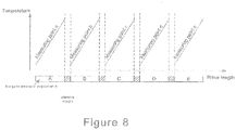
- the range of wavelengths that each FBG operates over need to be distinct from each other FBG's range of operating wavelengths. This is illustrated by way of example in Figure 8 . This is necessary to enable a single wavelength to relate to a specific FBG and a specific operating condition.
- Such systems require a broad band light source and a broad band interrogator, or a narrow band tunable light source, which results in significant overall cost of the system.
- LPGs suffer from similar problems.
- GB2372100 describes an optical waveguide Bragg grating system containing a set of Bragg gratings at each of a number of locations. Each location is assigned a unique digital code defining the wavelength set of the gratings at that location.
- WO2006107278 describes an optical fiber having at least a first fiber Bragg grating (FBG) and a second FBG formed therein; subjecting the optical fiber to a strain inducing force such that a grating period in the first FBG compresses and a grating period in the second FBG extends and optically interrogating the first and second FBG to determine peak reflection wavelengths of the first and second FBGs respectively, whereby a separation between the peak reflection wavelengths of the first and second FBGs is representative of the strain induced.
- FBG fiber Bragg grating
- GB2348000 describes a strain sensor that comprises an optical waveguide having a plurality of reflecting structure (Bragg gratings) along its length. Each structure reflects light at a different characteristic wavelength which changes according to the physical length of at least part of the reflecting structure.
- JP2004145382 describes a monitoring system using optical fibre sensors in which a wavelength measurement to be assigned to each optical fiber sensor is partially overlapped.
- an optical fibre sensor system for measuring at a plurality of locations an operating condition
- the sensor comprising: a sensor optical fibre; a light source for inputting light into the sensor optical fibre; a light detector for receiving light from the sensor optical fibre; and a processor for outputting measurements of the operating condition corresponding to the plurality of locations based on light received at the light detector, wherein the operating conditions at the plurality of locations are coupled such that an increase in one operating condition results in an increase in the other operating conditions, and vice versa.
- the optical fibre sensor comprises a plurality of optical gratings, each grating in use being disposed at a respective location on the wind turbine component and arranged to operate over a respective range of wavelengths depending on variations in the operating condition.
- a first of the plurality of gratings is a master grating and is arranged to operate over a first wavelength range, the first wavelength range being distinct from a second range of wavelengths over which the other gratings are arranged to operate.
- the other gratings are arranged such that the respective wavelength ranges over which they operate are spaced apart from the first wavelength range by a respective predetermined interval and such that they overlap with the respective wavelength range of at least one adjacent other grating, wherein the amount by which the respective ranges of wavelengths of the other gratings overlap is such that for each of the other gratings there is a range of unambiguous wavelengths that are unique for that grating and a range of ambiguous wavelengths that overlap with the wavelengths of the adjacent grating.
- the processor is operable to determine the value of the operating condition at the location of the master grating from the wavelength value received in the first wavelength range, and to determine the value of an operating condition at the location of one of the other gratings based on the wavelength value received in the first wavelength range, a wavelength value received in the second wavelength range, and the predetermined intervals by which the overlapping ranges are spaced apart from one another.
- arranged to operate means interact with light at a wavelength that falls within the allocated range of wavelengths and that varies within the range depending on variations in the operating condition".
- the cost of a sensor for measuring multiple operating conditions may be reduced.
- the cost may be reduced since the range of wavelengths that the light source, and the light detector, operate over can be reduced for the same number of measurements.
- the light having a wavelength in the first wavelength range is uniquely indicative of the value of the operating condition at the location of the master grating.
- the processor is operable to determine a reference wavelength value for a first one of the other gratings, the reference value indicating for the first one of the other gratings, the wavelength in the grating's respective range of wavelengths that corresponds to the value of the operating condition measured at the master grating.
- the reference wavelength value for the grating is calculated by adding or subtracting the respective predetermined interval from the wavelength value received in the first wavelength range.
- the processor is operable to determine the value of the operating condition at the first one of the other gratings by determining the difference between the reference wavelength value for the grating and the closest received wavelength value.
- the amount by which the respective ranges of wavelengths of the other gratings overlap is such that for each of the other gratings there is a range of unambiguous wavelengths that are unique for that grating and a range of ambiguous wavelengths that overlap with the wavelengths of the adjacent grating.
- the sensor system may also comprise a memory.
- the processor is operable to store a time series of measurements of wavelength in the memory for each of the other gratings, and the processor is operable to determine the value of the operating condition at the first one of the other gratings by determining the difference between the reference wavelength value and a received wavelength value falling in the ambiguous wavelengths for the first one of the other gratings, and by comparing the received wavelength value to historic values of the wavelength in the time series of measurements.
- the second wavelength range is divided into lower and upper second wavelength ranges, and the first range of wavelengths lies in between the lower and upper ranges.
- the first and second wavelength ranges are separated from one another by a margin of unused wavelengths.
- a method of operating an optical fibre sensor system comprising a sensor optical fibre having a plurality of optical gratings, each grating in use being disposed at a respective measurement location and arranged to operate over a respective range of wavelengths depending on variations in an operating condition of the measurement location, wherein the operating conditions at the measurement locations are coupled such that an increase in one operating condition results in an increase in the other operating conditions, and vice versa
- the method comprising: allocating a first range of unique measurement wavelengths to a master grating in the optical fibre; allocating respective ranges of measurement wavelengths to further gratings in the optical fibre, wherein the ranges allocated to the further gratings are distinct from the first range of unique measurement wavelengths and separated from the first range by predetermined intervals, and wherein the ranges allocated to each of the further gratings overlap with at least one adjacent further grating, wherein the amount by which the respective ranges of wavelengths of the further gratings overlap is such that
- the method further comprises determining a reference wavelength value for a first one of the other gratings, the reference value indicating for the first one of the other gratings, the wavelength in the grating's respective range of wavelengths that corresponds to the value of the operating condition measured at the master grating, and the reference wavelength value for the grating is calculated by adding or subtracting the respective predetermined interval from the wavelength value received in the first wavelength range. More preferably, the method also comprises determining the value of the operating condition at the first one of the other gratings by determining the difference between the reference wavelength value for the grating and the closest received wavelength value.
- the amount by which the respective ranges of wavelengths of the other gratings overlap is such that for each of the other gratings there is a range of unambiguous wavelengths that are unique for that grating and a range of ambiguous wavelengths that overlap with the wavelengths of the adjacent grating.
- the method further comprises : storing a time series of measurements of wavelength in the memory for each of the other gratings, and determining the value of the operating condition at the first one of the other gratings by determining the difference between the reference wavelength value and a received wavelength value falling in the ambiguous wavelengths for the first one of the other gratings, and by comparing the received wavelength value to historic values of the wavelength in the time series of measurements.
- the second wavelength range is divided into lower and upper second wavelength ranges, and the first range of wavelengths lies in between the lower and upper ranges.
- the first and second wavelength ranges are separated from one another by a margin of unused wavelengths.
- a computer program product having computer code stored thereon which when executed on a processor causes the processor to carry out a method as described herein.
- the optical fibre comprises a first Fibre Bragg Grating adapted to operate over a first range of wavelengths, and at least one set of further Fibre Bragg Gratings adapted to operate over a second range of wavelengths.
- Each Fibre Bragg Grating within the set is adapted to operate over a portion of the second range of wavelengths.
- each Fibre Bragg Grating within the set has an operating range that partially overlaps with at least one other such Fibre Bragg Grating operating range.
- the first range of wavelengths does not overlap with the second range of wavelengths. This enables the first grating to be used to unambiguously determine a range of expected operating conditions for the other gratings.
- the optical fibre may also comprise a second set of further gratings adapted to operate over a third range of wavelengths.
- Each grating in the second set is adapted to operate over a portion of the third range, and each grating within the set has an operating range that partially overlaps with at least one other such grating operating range.
- the first range of wavelengths is between the second range and the third range.
- a single grating may be used to unambiguously determine two ranges of expected operating conditions, the first range for the first set of gratings and the second range for the second set of gratings.
- the fibre optic sensor also comprises a light source for feeding light into the at least one optical fibre, a light detector for detecting light that has travelled along the at least one fibre, and a controller for determining, from the detected light, the wavelengths of light interacting with the gratings.
- This arrangement allows the sensor to be implemented using only a small number of optical components, and therefore provides advantages in cost, installation and maintenance.
- the invention extends to apparatus and/or methods substantially as herein described with reference to the accompanying drawings.
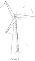
- Figure 1 illustrates a wind turbine 1, comprising a wind turbine tower 2 on which a wind turbine nacelle 3 is mounted.
- a wind turbine rotor 4 comprising at least one wind turbine blade 5 is mounted on a hub 6.
- the hub 6 is connected to the nacelle 3 through a low speed shaft (not shown) extending from the nacelle front.
- the wind turbine illustrated in Figure 1 may be a small model intended from domestic or light utility usage, or may be a large model, such as those that are suitable for use in large scale electricity generation on a wind farm for example. In the latter case, the diameter of the rotor could be as large as 100 metres or more.
- Figure 2 illustrates one example of an optical fibre for use in an optical fibre sensor system according to the invention.
- the optical fibre described contains a plurality of gratings, it will be appreciated that the optical fibre according to the invention could be constructed with a plurality of LPGs, or indeed any other suitable wavelength-selective optical grating.
- the optical fibre 200 comprises a fibre core 201, and a fibre cladding 202.
- the fibre core is provided with two sets of Fibre Bragg Gratings (FBGs) 203, 204, 205, 206 and 207 in FBG set 208, and FBGs 209, 210, 211, and 212 in FBG set 213.
- the FBG sets 208 and 213 correspond to FBGs A to D and F to I respectively in Figures 5(a) and 5(b)
- FBG 203 corresponds to FBG E.
- Each FBG is tuned in the sense that it will reflect a different wavelength of light determined by the grating dimensions.
- the section of the optical fibre 20 having an FBG is placed next to or in contact with a wind turbine component, then the changes in the length of the optical fibre at that location (for example, due to a temperature change of the component or a change in strain), will result in a change in both the dimensions of the FBG and the refractive index of the optical fibre. Both effects alter the wavelength of any light reflected and/or transmitted by the FBG, which can therefore be used as a measure of the temperature or strain of the component at that location.
- FIG. 3 illustrates an embodiment of an optical fibre sensor system according to an example of the invention.
- the sensor 300 comprises a light emitting device 301, such as an LED, laser, halogen or metal halide source, a light collecting measuring device or detector 302, such as a photo-sensor, and an optical fibre 200 (for conciseness only FBG set 208 is shown).
- the light emitting device is connected to one end of the fibre optic cable to input light into the fibre, and the light measuring device (such as an interrogator) is connected to the other to receive light transmitted along the fibre.
- An interrogator is a light detector that detects and measures light across a wide spread of wavelengths.
- a controller 303 is connected to both light emitting device 301 and light measuring device 302, by connections 304 and 305, such as wires or cables.
- Components 301 to 305 may be housed in a mounting box, or the like, for easy attachment to the inside or outside of a wind turbine component.
- FIG 4 illustrates the controller 303 as described above with reference to Figure 3 .
- the controller comprises a light source controller 400, coupled to the light source 301.
- the light source controller is used to determine when the light source is operated.
- the controller also comprises a memory 401 for storing the output received from the light detector.
- An analyser 402 such as a processor, and coupled to the memory, is provided to analyse the output from the light detector 302 stored in memory and determine the wavelengths of light reflected by the FBGs.
- a calculation unit 403 is coupled to the analyser 402 to calculate the difference between the wavelength received from each FBG and a reference wavelength expected if there were no temperature or strain difference, for example, between the FBGs (A, B, C or D) and FBG E.
- the calculation unit 403 is also coupled to the memory 401.
- the memory 401 is adapted to store a look-up table, and the look-up table is provided to allow the calculation unit to look-up the expected range of wavelengths for each FBG. The calculation unit then determines the value of the operating condition measured by FBG.
- the controller further comprises an input/output line 404 for receiving and transmitting instructions or data to and from a remote site, such as a monitoring station.
- the input/output line may be wired or wireless.
- error detection can be incorporated into the controller 303. If no wavelength is detected within the expected range for a particular FBG, then this could be an indication of a fault. This could be the result of a breakdown in the coupling between the operating conditions being measured, or that the FBG itself is faulty.
- controller has been described in terms of separate hardware components, this is solely to illustrate the functionality of the controller in a clear manner. It would be possible in practice to provide the hardware components as software or hardware, or as any combination of single or combined components.
- the optical fibre 200 is mounted on or in a wind turbine component (not shown in Figure 3 ) to measure the strain in the component, or indeed any other suitable operating condition of the component, such as temperature. In one example, this may be achieved by mounts attached to the outside or inside surface of the component. Other mounting methods would be acceptable as would be known to the skilled person. If the sensor were to be installed in a wind turbine to measure the strain in the wind turbine blades, it is likely that the mounting box would be situated in the hub 6, and the optical fibre 200 would extend internally within the blade from the hub to the relevant region of the blade to be assessed. In this way, the aerodynamic properties of the blades are not affected by the presence of the sensor. In other locations, the optic fibre sensor may be mounted on the outside of the component.
- the optical fibre sensor system described can therefore be utilised to measure a number of operating conditions, one operating condition per FBG. However, it is required that those operating conditions are coupled (i.e. that an increase in one operating condition results increase in the other operating conditions, and vice versa).
- the operating conditions could be the temperature of a number of components housed within the electrical housing of a wind turbine since it would be expected that a rise in temperature of one component would lead to a rise in temperature of another component, and vice versa.
- the overall range of temperatures that could be measured can be large, for example from -40 degrees C to 60 degrees C.
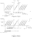
- optical fibre sensor system The operation of the optical fibre sensor system will now be described in more detail, and with reference to Figures 2 , 5a and 5b .
- the use of the sensor to detect temperature only will be described.
- the operation of the sensor will be the same for other operating conditions that are to be measured.
- the FBGs are configured to reflect light back to the detector, rather than transmit light to a remote detector at the end of the optical fibre 200. In practice, either or both configurations are acceptable.
- optical fibre 200 comprises a number of FBG's A to I, each tuned to a different wavelength and each located at a different location on the component where measurements are to be taken.
- FBG E is tuned to a first default wavelength, lying in the middle of the range of wavelengths of light that can be transmitted along the optical fibre 200 and detected by the light detector 302.
- a first range of measurement wavelengths is allocated to FBG E for use, which corresponds to the range of temperatures that FBG E will be used to detect.
- the range of wavelengths is illustrated as extending between ⁇ emin and ⁇ emax, with ⁇ emid signifying the middle value of the range.
- the FBG E is required to detect temperatures in the range of say -40 to 60 degrees C
- the FBG E will be constructed in the optical fibre 200 so that when the optical fibre 200 at FBG E is at -40 degrees C, the wavelength of light reflected by the FBG E will equal ⁇ emin, and so that when the optical fibre 200 at FBG E is at 60 degrees C, the wavelength of light reflected by the FBG E will equal ⁇ emax.
- FBG E will reflect light at ⁇ emid at 10 degrees.
- FBG E is allocated a unique and distinct range of wavelengths for the expected range of the operating parameter being measured.
- the controller 303 can unambiguously recognise that signal as being representative of the temperature of FBG E (and therefore the temperature of the component at that location) and no other.
- FBG E shall be referred to as a calibration FBG.
- FBGs A to D and F to I are allocated respective ranges of wavelengths between ⁇ nmin and ⁇ nmax (where n is representative of A, B, C, D, F, G, H and I). It is assumed that each of the FBGs will operate over the same range of temperatures as FBG E, and in this example therefore, each FBG will be used to detected temperatures in the range -40 to 60 degrees C but at different locations of the component. As above, each FBG will be constructed so that as the temperature of the FBG varies, the wavelength of light reflected varies between the maximum and minimum allotted wavelength values.
- each of the FBGs A to D and F to I would therefore require a unique range of operating wavelengths to be distinguished from one another and provide unambiguous temperature measurements in the manner described for FBG E.
- the respective ranges of wavelengths of the FBGs A to D and F to I are overlapped with at least one adjacent FBG (excluding FBG E). This advantageously provides a reduction in the total range of wavelengths that must be accommodated by the fibre and the sensor system, but does mean that in certain scenarios the signals provided by each of the FBGs A to D and F to I are no longer unambiguous.
- Calibration FBG E is therefore used to determine the expected range of temperatures measured at FBGs A to D and FBGs F to I (this can be achieved as it assumed that the locations where the FBGs are located are thermally coupled, meaning that there will be some correspondence between temperatures at different locations) as well as distinguish the values of the different FBGs from one another. For this reason FBGs A to D and F to I will be referred to as subsidiary FBGs, to indicate their dependence on calibration FBG E.
- FBG E is constructed to operate over wavelengths ⁇ emin to ⁇ emax.
- FBGs A to D are allocated lower ranges of wavelengths in comparison to the range allocated to FBG E, while FBGs F to I are allocated higher ranges.
- the range of wavelengths allocated to FBGs D and F are adjacent to that allocated to FBG E.
- the minimum allocated wavelength of FBG F ⁇ fmin and the maximum allocated wavelength of FBG D ⁇ dmax are separated from the range for FBG E by a tolerance value a. This tolerance value is intended to accommodate any imprecision in the manufacturing technique and allow for possible deviations in the constructed wavelength of the respective FBGs.
- Each allocated range of wavelengths will necessarily have a midpoint ⁇ nmid around which the range is centered.
- the maximum expected variation of wavelengths for FBG E is the range of wavelengths between the midpoint ⁇ emid and either ⁇ emin or ⁇ emax.
- the difference in the base wavelengths of each of the ranges for FBGs A to D or FBGs F to I is set to be this maximum variation for FBG E plus the tolerance alpha. This ensures that the overlapping ranges of wavelengths are not spaced out too much (in which case the reduction in bandwidth is diminished), but are also not too close together (in which case the accuracy of the sensor could be impaired).
- controller 303 processes the light signals received from the optical fibre 200 and resolves any ambiguities between signals received from different FBGs.
- the temperature of the optical fibre 200 is the same at each of the different FBG locations A to I.
- Light source controller 400 instructs light source 301 to input light into the optical fibre 200, and as a result light is reflected back from each of the FBGs A to I and is detected at light detector 302.
- Analyser 402 scans through the nine signals received from the respective FBGs A to I to detect the signal reflected back by calibration FBG E.
- the signal from FBG E can be distinguished from the other FBGs as (assuming the temperature of the component has not gone outside of the expected range of temperatures) it will always lie in the dedicated range of unique wavelengths ⁇ emin or ⁇ emax. From the measurement ⁇ e the temperature of the component at location E can be determined by analyser 402 and calculation unit 403. This value will also be stored in memory 401 with a time stamp information. Referring to Figure 5b , this first temperature is denoted as T1.
- the wavelength of the light signals reflected by the FBGs A to D and F to I when those FBGs are all at the same temperature can be calculated by the analyser and calculation unit 403.
- the wavelength of light that corresponds to the same temperature as the FBG E shall be referred to as the reference wavelength for the FBG (it will be appreciated that this will vary with variations in temperature).
- the difference in expected wavelengths between FBGs E and D at the same temperature can be given by the difference in the centre of the ranges ( ⁇ emid - ⁇ dmid) for example (the minimum or maximum values of the ranges could also be used).
- the difference in expected wavelengths between FBGs E and C at the same temperature can be given by the difference in the centre of the ranges ( ⁇ emid - ⁇ cmid) for example (again the minimum or maximum values of the ranges could also be used).
- the wavelengths for the same temperature T1 at each of the different locations A to D and F to I can be readily determined by subtraction or addition of a respective predetermined interval. This interval will be different for each FBG range, and may be measured relative to the adjacent FBG range or to the range of wavelengths for FBG E.
- the horizontal bars A, B C and D underneath the wavelength axis indicate how the ranges of wavelengths that can be detected at the FBGs A to D will change with temperature.
- the temperature at FBG E varies the other FBG's usable measurement range of wavelengths slides up or down the wavelengths available.
- the analyser 402 and calculation unit 403 assume that each of the FBGs A to D are operating in the unshaded unambiguous wavelength range indicated directly underneath the wavelength axis.
- temperature T2 those ranges of unambiguous wavelengths are shifted down. Due to the assumed thermal coupling between FBG E and the other FBGs, once the temperature at FBG E is determined, the expected operating range at the other subsidiary FBGs can be readily determined.
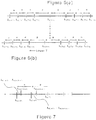
- the temperature at the locations being monitored by the other FBGs A to D and I to F will not be identical to FBG E, and the signals reflected back to the light detector 302 and the analyser 402 will not exhibit the regular spacing illustrated in Figures 6a and 6b , but will be spaced irregularly as shown in Figure 7 .
- the irregular spacing is indicative of the temperature differences at each location.
- the calculation unit determines the difference between the reference wavelength (referred to as ⁇ n_ref) of FBG n, assuming that FBG n is at the same temperature as FBG E, and the actual signal that is detected from FBG n.
- ⁇ n_ref is calculable once Te is known, as explained above, and calculating the difference to give a temperature reading at FBG n is therefore simply a matter of subtraction or addition as shown in Figure 7 .
- the sensor system has two choices. In one implementation, the system simply disregards the sensor readings and gives an error message indicating that the received light signal wavelength no longer indicates an unambiguous wavelength but instead indicates one of at least two temperatures depending on which of the FBGs are believed to reflected the signal.
- the analyser 402 can process the signal falling into the shaded ambiguous wavelength regions and see if the originating FBG (and therefore the correct temperature and location can be determined). This can be achieved in a number of ways.
- the sensor system is configured to record the temperature and wavelength indications continuously over time.
- a received wavelength that falls in the shaded ambiguous portion of the wavelength axis can be compared against the received wavelengths for the immediately preceding time intervals.
- historic values of the received wavelength originated in the unshaded region of the wavelength axis and then drifted into the shaded ambiguous region as the temperature changed, potentially ambiguous wavelength values can be resolved simply be inspection and comparison of previous values. This does however assume that the wavelengths are sampled often enough for successive values to be relatable to one another.
- the analyser may simply assume that wavelength values in the ambiguous region of the wavelength range belong to the unambiguous FBG wavelength range to which they are closest. This introduces more room for error, but does mean that the analysis and processing overhead of the sensor is less.
- using the wavelength values in the ambiguous regions of the wavelength axis will be desirable or unnecessary depending on the degree of overlap between the adjacent ranges. It will be appreciated that taking the wavelength value that is closest to the reference value occurs ordinarily when the wavelength that is received lies in the unambiguous range of wavelengths. Operating based on the closest wavelength therefore allows the system to disregard the distinction between the unambiguous and ambiguous ranges altogether.
- the dedicated range of wavelengths of FBG E may overlap by a small amount (for example, by an amount less than the overlap of the wavelength ranges allocated to FBGs A and B).
- FBG locations are thermally coupled, even when the measured wavelength for FBG E lies in a range that is also allocated to FBG D (or FBG F) by analysing the wavelengths of light reflected by the other FBGS the temperature at FBG can be unambiguously determined.
Landscapes
- Physics & Mathematics (AREA)
- General Physics & Mathematics (AREA)
- Engineering & Computer Science (AREA)
- Aviation & Aerospace Engineering (AREA)
- Chemical & Material Sciences (AREA)
- Analytical Chemistry (AREA)
- Electromagnetism (AREA)
- Optical Transform (AREA)
- Length Measuring Devices By Optical Means (AREA)
- Measuring Temperature Or Quantity Of Heat (AREA)
Claims (20)
- Système de capteur à fibre optique (300) pour mesurer une condition de fonctionnement au niveau d'une pluralité d'emplacements, le capteur comprenant :une fibre optique de capteur (200) ;une source de lumière (301) pour entrer de la lumière dans la fibre optique de capteur ;un détecteur de lumière (302) pour recevoir de la lumière de la fibre optique de capteur ; etun processeur (303) pour produire en sortie des mesures de la condition de fonctionnement correspondant à la pluralité d'emplacements sur la base de la lumière reçue au niveau du détecteur de lumière (302) ; dans lequel les conditions de fonctionnement au niveau de la pluralité d'emplacements sont couplées de telle sorte qu'une augmentation d'une condition de fonctionnement entraîne une augmentation des autres conditions de fonctionnement, et vice versa ;dans lequel la fibre optique de capteur (200) comprend une pluralité de réseaux optiques (FBG 1-I), chaque réseau en utilisation étant disposé au niveau d'un emplacement respectif et agencé pour fonctionner sur une plage de longueurs d'onde respective en fonction de variations de la condition de fonctionnement ; caractérisé en ce que :un premier de la pluralité de réseaux est un réseau maître (FBG E) et est agencé pour fonctionner sur une première plage de longueurs d'onde, la première plage de longueurs d'onde étant distincte d'une seconde plage de longueurs d'onde sur laquelle sont agencés pour fonctionner les autres réseaux, etdans lequel les autres réseaux (FBG A-D et FBG F-I) sont agencés de telle sorte que les plages de longueur d'onde respectives sur lesquelles ils fonctionnent sont espacées de la première plage de longueurs d'onde d'un intervalle prédéterminé respectif et de telle sorte qu'ils chevauchent la plage de longueurs d'onde respective d'au moins un autre réseau adjacent ;dans lequel la quantité de laquelle les plages de longueurs d'onde respectives des autres réseaux se chevauchent est telle que pour chacun des autres réseaux il existe une plage de longueurs d'onde non ambiguës qui sont uniques pour ce réseau et une plage de longueurs d'onde ambiguës qui chevauchent les longueurs d'onde du réseau adjacent ;dans lequel le processeur (303) permet de déterminer la valeur de la condition de fonctionnement au niveau de l'emplacement du réseau maître à partir de la valeur de longueur d'onde reçue dans la première plage de longueurs d'onde, et de déterminer la valeur d'une condition de fonctionnement au niveau de l'emplacement de l'un des autres réseaux sur la base de la valeur de longueur d'onde reçue dans la première plage de longueurs d'onde, une valeur de longueur d'onde reçue dans la seconde plage de longueurs d'onde, et les intervalles prédéterminés desquels les plages chevauchantes sont espacées les unes des autres.
- Système de capteur (300) selon la revendication 1, dans lequel la lumière ayant une longueur d'onde dans la première plage de longueurs d'onde est uniquement indicative de la valeur de la condition de fonctionnement au niveau de l'emplacement du réseau maître.
- Système de capteur (300) selon la revendication 1 ou 2, dans lequel le processeur (303) permet de déterminer une valeur de longueur d'onde de référence pour un premier des autres réseaux, la valeur de référence indiquant pour le premier des autres réseaux, la longueur d'onde dans la plage de longueurs d'onde respective du réseau qui correspond à la valeur de la condition de fonctionnement mesurée au niveau du réseau maître, et
dans lequel la valeur de longueur d'onde de référence pour le réseau est calculée en ajoutant ou soustrayant l'intervalle prédéterminé respectif de la valeur de longueur d'onde reçue dans la première plage de longueurs d'onde. - Système de capteur (300) selon la revendication 3, dans lequel le processeur (303) permet de déterminer la valeur de la condition de fonctionnement au niveau du premier des autres réseaux en déterminant la différence entre la valeur de longueur d'onde de référence pour le réseau et la valeur de longueur d'onde reçue la plus proche.
- Système de capteur (300) selon les revendications 3 ou 4, comprenant une mémoire (401), dans lequel le processeur (303) permet de stocker une série chronologique de mesures de longueur d'onde dans la mémoire pour chacun des autres réseaux, et
dans lequel le processeur (303) permet de déterminer la valeur de la condition de fonctionnement au niveau du premier des autres réseaux en déterminant la différence entre la valeur de longueur d'onde de référence et une valeur de longueur d'onde reçue tombant dans le cadre des longueurs d'onde ambiguës pour le premier des autres réseaux, et en comparant la valeur de longueur d'onde reçue aux valeurs historiques de la longueur d'onde dans la série chronologique de mesures. - Système de capteur (300) selon l'une quelconque des revendications précédentes, dans lequel la seconde plage de longueurs d'onde est divisée en des secondes plages de longueurs d'onde inférieure et supérieure, et la première plage de longueurs d'onde se trouve entre les plages inférieure et supérieure.
- Système de capteur (300) selon l'une quelconque des revendications précédentes, dans lequel les première et seconde plages de longueurs d'onde sont séparées l'une de l'autre par une marge de longueurs d'onde non utilisées.
- Système de capteur (300) selon l'une quelconque des revendications précédentes, dans lequel le réseau est un réseau de Bragg sur fibre ou un réseau sur fibre à longue période.
- Système de capteur (300) selon l'une quelconque des revendications précédentes, dans lequel la condition de fonctionnement est une ou plusieurs d'une température, d'une contrainte, d'une déformation ou d'une pression.
- Système de capteur (300) selon l'une quelconque des revendications précédentes, dans lequel la pluralité d'emplacements sont des emplacements respectifs sur un composant d'éolienne.
- Procédé de fonctionnement d'un système de capteur à fibre optique (300), le système comprenant une fibre optique de capteur (200) ayant une pluralité de réseaux (FBG A-I), chaque réseau en utilisation étant disposé au niveau d'un emplacement de mesure respectif et agencé pour fonctionner sur une plage de longueurs d'onde respective en fonction de variations d'une condition de fonctionnement de l'emplacement de mesure, dans lequel les conditions de fonctionnement au niveau des emplacements de mesure sont couplées de telle sorte qu'une augmentation d'une condition de fonctionnement entraîne une augmentation des autres conditions de fonctionnement, et vice versa, le procédé étant caractérisé en ce qu'il comprend :l'affectation d'une première plage de longueurs d'onde de mesure uniques à un réseau maître (FBG E) dans la fibre optique ;l'affectation de plages de longueurs d'onde de mesure respectives à d'autres réseaux (FBG A-D et FBG F-I) dans la fibre optique, dans lequel les plages affectées aux autres réseaux sont distinctes de la première plage de longueurs d'onde de mesure uniques et séparées de la première plage par des intervalles prédéterminés, et dans lequel les plages affectées à chacun des autres réseaux chevauchent au moins un autre réseau adjacent ;dans lequel la quantité de laquelle les pages de longueurs d'onde respectives des autres réseaux se chevauchent est telle que pour chacun des autres réseaux il existe une plage de longueurs d'onde non ambiguës qui sont uniques pour ce réseau et une plage de longueurs d'onde ambiguës qui chevauchent les longueurs d'onde du réseau adjacent ;la détermination de la valeur de la condition de fonctionnement au niveau de l'emplacement du réseau maître à partir d'une valeur de longueur d'onde reçue dans la première plage de longueurs d'onde de mesure uniques ;la détermination de la valeur d'une condition de fonctionnement au niveau de l'emplacement de l'un des autres réseaux sur la base de la valeur de longueur d'onde reçue dans la première plage de longueurs d'onde, d'une valeur de longueur d'onde reçue dans les plages de longueur d'onde affectées aux autres réseaux, et sur la base des intervalles prédéterminés desquels les plages chevauchantes sont espacées l'une de l'autre.
- Procédé selon la revendication 11, comprenant la détermination d'une valeur de longueur d'onde de référence pour un premier des autres réseaux, la valeur de référence indiquant pour le premier des autres réseaux, la longueur d'onde dans la plage de longueurs d'onde respective du réseau qui correspond à la valeur de la condition de fonctionnement mesurée au niveau du réseau maître, et
dans lequel la valeur de longueur d'onde de référence pour le réseau est calculée en ajoutant ou soustrayant l'intervalle prédéterminé respectif de la valeur de longueur d'onde reçue dans la première plage de longueurs d'onde. - Procédé selon la revendication 12, comprenant la détermination de la valeur de la condition de fonctionnement au niveau du premier des autres réseaux en déterminant la différence entre la valeur de longueur d'onde de référence pour le réseau et la valeur de longueur d'onde reçue la plus proche.
- Procédé selon la revendication 12 ou 13, comprenant :le stockage d'une série chronologique de mesures de longueur d'onde dans une mémoire (401) pour chacun des autres réseaux, etla détermination de la valeur de la condition de fonctionnement au niveau du premier des autres réseaux en déterminant la différence entre la valeur de longueur d'onde de référence et une valeur de longueur d'onde reçue tombant dans le cadre des longueurs d'onde ambiguës pour le premier des autres réseaux, et en comparant la valeur de longueur d'onde reçue aux valeurs historiques de la longueur d'onde dans la série chronologique de mesures.
- Procédé selon l'une quelconque des revendications 11 à 14, dans lequel la seconde plage de longueurs d'onde est divisée en des plages de longueurs d'onde inférieure et supérieure, et la première plage de longueurs d'onde se trouve entre les plages inférieure et supérieure.
- Procédé selon l'une quelconque des revendications 11 à 15, dans lequel les première et seconde plages de longueur d'onde sont séparées l'une de l'autre par une marge de longueurs d'onde non utilisées.
- Procédé selon l'une quelconque des revendications 11 à 16, dans lequel le réseau est un réseau de Bragg sur fibre ou un réseau sur fibre à longue période.
- Procédé selon l'une quelconque des revendications 11 à 17, dans lequel la condition de fonctionnement est une ou plusieurs d'une température, d'une contrainte, d'une déformation ou d'une pression.
- Procédé selon l'une quelconque des revendications 11 à 18, dans lequel la pluralité d'emplacements sont des emplacements respectifs sur un composant d'éolienne.
- Produit de programme informatique ayant un code informatique stocké sur celui-ci qui lorsqu'il est exécuté sur un processeur (303) amène le processeur à effectuer les étapes des revendications 11 à 19.
Applications Claiming Priority (3)
| Application Number | Priority Date | Filing Date | Title |
|---|---|---|---|
| US201161541134P | 2011-09-30 | 2011-09-30 | |
| DKPA201170542 | 2011-09-30 | ||
| PCT/DK2012/050345 WO2013044919A1 (fr) | 2011-09-30 | 2012-09-19 | Système et procédé de détection à réseau de diffraction à fibre optique |
Publications (2)
| Publication Number | Publication Date |
|---|---|
| EP2761263A1 EP2761263A1 (fr) | 2014-08-06 |
| EP2761263B1 true EP2761263B1 (fr) | 2019-01-09 |
Family
ID=47994301
Family Applications (1)
| Application Number | Title | Priority Date | Filing Date |
|---|---|---|---|
| EP12762530.9A Not-in-force EP2761263B1 (fr) | 2011-09-30 | 2012-09-19 | Système et procédé de détection à réseau de diffraction à fibre optique |
Country Status (5)
| Country | Link |
|---|---|
| US (1) | US9239249B2 (fr) |
| EP (1) | EP2761263B1 (fr) |
| CN (1) | CN104024815B (fr) |
| IN (1) | IN2014DN03226A (fr) |
| WO (1) | WO2013044919A1 (fr) |
Families Citing this family (9)
| Publication number | Priority date | Publication date | Assignee | Title |
|---|---|---|---|---|
| US9753050B2 (en) * | 2013-02-15 | 2017-09-05 | Vestas Wind Systems A/S | Wind turbine component having an optical fibre wind sensor |
| WO2014200986A1 (fr) * | 2013-06-13 | 2014-12-18 | Intuitive Surgical Operations, Inc. | Fibre de détection à réseau de bragg sur fibre à pas variable et à chevauchement, et procédés et appareil pour une mesure de paramètre à l'aide cette dernière |
| CN106471340B (zh) * | 2014-04-02 | 2019-07-23 | 克罗马森西有限公司 | 用于从多个光纤传感器测量光信号的装置 |
| CN107810397B (zh) * | 2015-06-24 | 2021-06-01 | 维斯塔斯风力系统集团公司 | 用于风力涡轮机的叶片负载感测系统 |
| US10254156B2 (en) * | 2015-10-29 | 2019-04-09 | Halliburton Energy Services, Inc. | Active error correction in an optical sensor system |
| JP6663369B2 (ja) * | 2017-02-13 | 2020-03-11 | 三菱重工業株式会社 | 風車翼の損傷検知方法及び風車 |
| JP2018145899A (ja) * | 2017-03-07 | 2018-09-20 | 株式会社日立製作所 | 風車ブレードまたは風力発電装置 |
| CN110646115A (zh) * | 2019-09-16 | 2020-01-03 | 江苏卓然智能重工有限公司 | 一种急冷换热器预应力伸长的fbg温度监测装置 |
| CN111678636A (zh) * | 2020-06-09 | 2020-09-18 | 西安航天动力研究所 | 一种非接触式压强测量装置及方法 |
Family Cites Families (21)
| Publication number | Priority date | Publication date | Assignee | Title |
|---|---|---|---|---|
| US5426297A (en) * | 1993-09-27 | 1995-06-20 | United Technologies Corporation | Multiplexed Bragg grating sensors |
| GB2348000B (en) * | 1999-03-19 | 2001-02-07 | Marconi Electronic Syst Ltd | Strain sensing |
| JP2000346722A (ja) * | 1999-06-07 | 2000-12-15 | Furukawa Electric Co Ltd:The | 力学センサ |
| GB2372100B (en) * | 2001-02-13 | 2003-04-16 | Marconi Caswell Ltd | Optical Waveguide Bragg Grating System |
| US6795599B2 (en) * | 2001-05-11 | 2004-09-21 | Vasilii V. Spirin | Differential fiber optical sensor with interference energy analyzer |
| NO334515B1 (no) * | 2002-03-13 | 2014-03-31 | Light Structures As | Fiberoptisk sensorpakke |
| JP2004145382A (ja) * | 2002-10-21 | 2004-05-20 | Sumitomo Electric Ind Ltd | 光ファイバセンサを利用した監視システム |
| US7129470B2 (en) * | 2003-06-04 | 2006-10-31 | Weatherford/Lamb, Inc. | Optical sensor using a long period grating suitable for dynamic interrogation |
| US7109471B2 (en) | 2004-06-04 | 2006-09-19 | Weatherford/Lamb, Inc. | Optical wavelength determination using multiple measurable features |
| US7060967B2 (en) | 2004-10-12 | 2006-06-13 | Optoplan As | Optical wavelength interrogator |
| EP1866607A4 (fr) * | 2005-04-05 | 2012-07-25 | Agency Science Tech & Res | Capteur de contraintes a fibres de capteur |
| US7702190B2 (en) * | 2005-04-05 | 2010-04-20 | Agency For Science, Technology And Research | Fiber Bragg grating sensor |
| US7697121B1 (en) * | 2005-11-30 | 2010-04-13 | Kotura, Inc. | Sensing system having wavelength reflectors that receive modulated light signals |
| KR100760510B1 (ko) * | 2006-05-26 | 2007-09-20 | 한국과학기술연구원 | 회전체의 이상감지장치 |
| GB2440954B (en) * | 2006-08-18 | 2008-12-17 | Insensys Ltd | Structural monitoring |
| JP4930034B2 (ja) | 2006-12-15 | 2012-05-09 | 日立電線株式会社 | 物理量測定システム |
| DE102008014644A1 (de) * | 2008-03-17 | 2009-10-01 | Siemens Aktiengesellschaft | Antriebswelle für eine Propellergondel mit Sensorik |
| CN100580383C (zh) * | 2008-10-17 | 2010-01-13 | 中国科学院上海光学精密机械研究所 | 嵌入式多通道高速光纤光栅传感器解调系统 |
| DE102009007142A1 (de) * | 2009-02-02 | 2010-08-05 | Draka Industrial Cable Gmbh | Faseroptische Messvorrichtung |
| US8019190B2 (en) * | 2009-03-30 | 2011-09-13 | General Electric Company | Optical sensors, systems, and methods of making |
| US8385692B2 (en) * | 2009-05-27 | 2013-02-26 | Baker Hughes Incorporated | On-line fiber Bragg grating dithering |
-
2012
- 2012-09-19 CN CN201280053532.0A patent/CN104024815B/zh not_active Expired - Fee Related
- 2012-09-19 US US14/347,976 patent/US9239249B2/en not_active Expired - Fee Related
- 2012-09-19 WO PCT/DK2012/050345 patent/WO2013044919A1/fr active Application Filing
- 2012-09-19 IN IN3226DEN2014 patent/IN2014DN03226A/en unknown
- 2012-09-19 EP EP12762530.9A patent/EP2761263B1/fr not_active Not-in-force
Non-Patent Citations (1)
| Title |
|---|
| None * |
Also Published As
| Publication number | Publication date |
|---|---|
| CN104024815B (zh) | 2016-06-22 |
| US20140239166A1 (en) | 2014-08-28 |
| IN2014DN03226A (fr) | 2015-05-22 |
| WO2013044919A1 (fr) | 2013-04-04 |
| CN104024815A (zh) | 2014-09-03 |
| EP2761263A1 (fr) | 2014-08-06 |
| US9239249B2 (en) | 2016-01-19 |
Similar Documents
| Publication | Publication Date | Title |
|---|---|---|
| EP2761263B1 (fr) | Système et procédé de détection à réseau de diffraction à fibre optique | |
| EP2643663B1 (fr) | Système détecteur à fibre optique longue dans un élément d'éolienne | |
| US8348611B2 (en) | Wind turbine having a sensor system for detecting deformation in a wind turbine rotor blade and corresponding method | |
| EP3062131B1 (fr) | Procédé de détection de détériorations de pales de turbine éolienne et éolienne | |
| CN101308598B (zh) | 光纤光栅感温火灾探测系统 | |
| EP3361093B1 (fr) | Procédé de détection de détériorations de pales de turbine éolienne et éolienne | |
| RU2016101220A (ru) | Внутрискважинная утяжеленная оптимизационная бурильная труба с оптоволокном | |
| CN115248064A (zh) | 一种电池模组检测方法及检测系统 | |
| CN101046450B (zh) | 光纤光栅甲烷检测的方法和设备 | |
| EP3961163B1 (fr) | Système de mesure de quantité de fluide | |
| EP3967996A2 (fr) | Capteurs de charge à fibres optiques et systèmes associés | |
| KR101474068B1 (ko) | 광섬유 브래그 격자를 이용한 원전 환경 모니터링 시스템 | |
| CN116972957A (zh) | 一种输电gil管道的振动检测方法和系统 | |
| CN201111993Y (zh) | 智能监控型电力电缆 | |
| CN112629698A (zh) | 一种基于光纤光栅的温度检测装置 | |
| ES2706991T3 (es) | Sistema de sensor de rejilla de fibra óptica y método | |
| CN205982113U (zh) | 风力发电机组的裂纹检测装置及风力发电机组 | |
| CN111486998A (zh) | 一种基于光纤布拉格光栅的弹药压力监测装置 | |
| CN214407808U (zh) | 一种基于光纤光栅的温度检测装置 | |
| EP2547993B1 (fr) | Capteur infrarouge à fibres optiques | |
| CN217930613U (zh) | 基于光纤传感技术的高压釜温度监测系统 | |
| CN101424627A (zh) | 一种光纤光栅传感器 | |
| CN101424624A (zh) | 一种光纤光栅传感器 | |
| GB2462603A (en) | Light source variation compensating interferometric fibre optic sensor in a wind turbine component | |
| CN117232637A (zh) | 振动应变检测光缆、传感系统及其使用方法、煤矿皮带机 |
Legal Events
| Date | Code | Title | Description |
|---|---|---|---|
| PUAI | Public reference made under article 153(3) epc to a published international application that has entered the european phase |
Free format text: ORIGINAL CODE: 0009012 |
|
| 17P | Request for examination filed |
Effective date: 20140325 |
|
| AK | Designated contracting states |
Kind code of ref document: A1 Designated state(s): AL AT BE BG CH CY CZ DE DK EE ES FI FR GB GR HR HU IE IS IT LI LT LU LV MC MK MT NL NO PL PT RO RS SE SI SK SM TR |
|
| DAX | Request for extension of the european patent (deleted) | ||
| RAP1 | Party data changed (applicant data changed or rights of an application transferred) |
Owner name: VESTAS WIND SYSTEMS A/S |
|
| STAA | Information on the status of an ep patent application or granted ep patent |
Free format text: STATUS: EXAMINATION IS IN PROGRESS |
|
| 17Q | First examination report despatched |
Effective date: 20180212 |
|
| GRAP | Despatch of communication of intention to grant a patent |
Free format text: ORIGINAL CODE: EPIDOSNIGR1 |
|
| STAA | Information on the status of an ep patent application or granted ep patent |
Free format text: STATUS: GRANT OF PATENT IS INTENDED |
|
| INTG | Intention to grant announced |
Effective date: 20180820 |
|
| GRAS | Grant fee paid |
Free format text: ORIGINAL CODE: EPIDOSNIGR3 |
|
| GRAA | (expected) grant |
Free format text: ORIGINAL CODE: 0009210 |
|
| STAA | Information on the status of an ep patent application or granted ep patent |
Free format text: STATUS: THE PATENT HAS BEEN GRANTED |
|
| AK | Designated contracting states |
Kind code of ref document: B1 Designated state(s): AL AT BE BG CH CY CZ DE DK EE ES FI FR GB GR HR HU IE IS IT LI LT LU LV MC MK MT NL NO PL PT RO RS SE SI SK SM TR |
|
| REG | Reference to a national code |
Ref country code: GB Ref legal event code: FG4D |
|
| REG | Reference to a national code |
Ref country code: CH Ref legal event code: EP Ref country code: AT Ref legal event code: REF Ref document number: 1087910 Country of ref document: AT Kind code of ref document: T Effective date: 20190115 |
|
| REG | Reference to a national code |
Ref country code: DE Ref legal event code: R096 Ref document number: 602012055722 Country of ref document: DE |
|
| REG | Reference to a national code |
Ref country code: IE Ref legal event code: FG4D |
|
| REG | Reference to a national code |
Ref country code: ES Ref legal event code: FG2A Ref document number: 2706991 Country of ref document: ES Kind code of ref document: T3 Effective date: 20190402 |
|
| REG | Reference to a national code |
Ref country code: NL Ref legal event code: MP Effective date: 20190109 |
|
| REG | Reference to a national code |
Ref country code: LT Ref legal event code: MG4D |
|
| PG25 | Lapsed in a contracting state [announced via postgrant information from national office to epo] |
Ref country code: NL Free format text: LAPSE BECAUSE OF FAILURE TO SUBMIT A TRANSLATION OF THE DESCRIPTION OR TO PAY THE FEE WITHIN THE PRESCRIBED TIME-LIMIT Effective date: 20190109 |
|
| REG | Reference to a national code |
Ref country code: AT Ref legal event code: MK05 Ref document number: 1087910 Country of ref document: AT Kind code of ref document: T Effective date: 20190109 |
|
| PG25 | Lapsed in a contracting state [announced via postgrant information from national office to epo] |
Ref country code: PL Free format text: LAPSE BECAUSE OF FAILURE TO SUBMIT A TRANSLATION OF THE DESCRIPTION OR TO PAY THE FEE WITHIN THE PRESCRIBED TIME-LIMIT Effective date: 20190109 Ref country code: LT Free format text: LAPSE BECAUSE OF FAILURE TO SUBMIT A TRANSLATION OF THE DESCRIPTION OR TO PAY THE FEE WITHIN THE PRESCRIBED TIME-LIMIT Effective date: 20190109 Ref country code: FI Free format text: LAPSE BECAUSE OF FAILURE TO SUBMIT A TRANSLATION OF THE DESCRIPTION OR TO PAY THE FEE WITHIN THE PRESCRIBED TIME-LIMIT Effective date: 20190109 Ref country code: NO Free format text: LAPSE BECAUSE OF FAILURE TO SUBMIT A TRANSLATION OF THE DESCRIPTION OR TO PAY THE FEE WITHIN THE PRESCRIBED TIME-LIMIT Effective date: 20190409 Ref country code: PT Free format text: LAPSE BECAUSE OF FAILURE TO SUBMIT A TRANSLATION OF THE DESCRIPTION OR TO PAY THE FEE WITHIN THE PRESCRIBED TIME-LIMIT Effective date: 20190509 Ref country code: SE Free format text: LAPSE BECAUSE OF FAILURE TO SUBMIT A TRANSLATION OF THE DESCRIPTION OR TO PAY THE FEE WITHIN THE PRESCRIBED TIME-LIMIT Effective date: 20190109 |
|
| PG25 | Lapsed in a contracting state [announced via postgrant information from national office to epo] |
Ref country code: GR Free format text: LAPSE BECAUSE OF FAILURE TO SUBMIT A TRANSLATION OF THE DESCRIPTION OR TO PAY THE FEE WITHIN THE PRESCRIBED TIME-LIMIT Effective date: 20190410 Ref country code: IS Free format text: LAPSE BECAUSE OF FAILURE TO SUBMIT A TRANSLATION OF THE DESCRIPTION OR TO PAY THE FEE WITHIN THE PRESCRIBED TIME-LIMIT Effective date: 20190509 Ref country code: LV Free format text: LAPSE BECAUSE OF FAILURE TO SUBMIT A TRANSLATION OF THE DESCRIPTION OR TO PAY THE FEE WITHIN THE PRESCRIBED TIME-LIMIT Effective date: 20190109 Ref country code: HR Free format text: LAPSE BECAUSE OF FAILURE TO SUBMIT A TRANSLATION OF THE DESCRIPTION OR TO PAY THE FEE WITHIN THE PRESCRIBED TIME-LIMIT Effective date: 20190109 Ref country code: RS Free format text: LAPSE BECAUSE OF FAILURE TO SUBMIT A TRANSLATION OF THE DESCRIPTION OR TO PAY THE FEE WITHIN THE PRESCRIBED TIME-LIMIT Effective date: 20190109 Ref country code: BG Free format text: LAPSE BECAUSE OF FAILURE TO SUBMIT A TRANSLATION OF THE DESCRIPTION OR TO PAY THE FEE WITHIN THE PRESCRIBED TIME-LIMIT Effective date: 20190409 |
|
| REG | Reference to a national code |
Ref country code: DE Ref legal event code: R097 Ref document number: 602012055722 Country of ref document: DE |
|
| PG25 | Lapsed in a contracting state [announced via postgrant information from national office to epo] |
Ref country code: AL Free format text: LAPSE BECAUSE OF FAILURE TO SUBMIT A TRANSLATION OF THE DESCRIPTION OR TO PAY THE FEE WITHIN THE PRESCRIBED TIME-LIMIT Effective date: 20190109 Ref country code: RO Free format text: LAPSE BECAUSE OF FAILURE TO SUBMIT A TRANSLATION OF THE DESCRIPTION OR TO PAY THE FEE WITHIN THE PRESCRIBED TIME-LIMIT Effective date: 20190109 Ref country code: CZ Free format text: LAPSE BECAUSE OF FAILURE TO SUBMIT A TRANSLATION OF THE DESCRIPTION OR TO PAY THE FEE WITHIN THE PRESCRIBED TIME-LIMIT Effective date: 20190109 Ref country code: SK Free format text: LAPSE BECAUSE OF FAILURE TO SUBMIT A TRANSLATION OF THE DESCRIPTION OR TO PAY THE FEE WITHIN THE PRESCRIBED TIME-LIMIT Effective date: 20190109 Ref country code: EE Free format text: LAPSE BECAUSE OF FAILURE TO SUBMIT A TRANSLATION OF THE DESCRIPTION OR TO PAY THE FEE WITHIN THE PRESCRIBED TIME-LIMIT Effective date: 20190109 Ref country code: DK Free format text: LAPSE BECAUSE OF FAILURE TO SUBMIT A TRANSLATION OF THE DESCRIPTION OR TO PAY THE FEE WITHIN THE PRESCRIBED TIME-LIMIT Effective date: 20190109 Ref country code: AT Free format text: LAPSE BECAUSE OF FAILURE TO SUBMIT A TRANSLATION OF THE DESCRIPTION OR TO PAY THE FEE WITHIN THE PRESCRIBED TIME-LIMIT Effective date: 20190109 Ref country code: IT Free format text: LAPSE BECAUSE OF FAILURE TO SUBMIT A TRANSLATION OF THE DESCRIPTION OR TO PAY THE FEE WITHIN THE PRESCRIBED TIME-LIMIT Effective date: 20190109 |
|
| PLBE | No opposition filed within time limit |
Free format text: ORIGINAL CODE: 0009261 |
|
| STAA | Information on the status of an ep patent application or granted ep patent |
Free format text: STATUS: NO OPPOSITION FILED WITHIN TIME LIMIT |
|
| PG25 | Lapsed in a contracting state [announced via postgrant information from national office to epo] |
Ref country code: SM Free format text: LAPSE BECAUSE OF FAILURE TO SUBMIT A TRANSLATION OF THE DESCRIPTION OR TO PAY THE FEE WITHIN THE PRESCRIBED TIME-LIMIT Effective date: 20190109 |
|
| 26N | No opposition filed |
Effective date: 20191010 |
|
| PG25 | Lapsed in a contracting state [announced via postgrant information from national office to epo] |
Ref country code: SI Free format text: LAPSE BECAUSE OF FAILURE TO SUBMIT A TRANSLATION OF THE DESCRIPTION OR TO PAY THE FEE WITHIN THE PRESCRIBED TIME-LIMIT Effective date: 20190109 |
|
| PG25 | Lapsed in a contracting state [announced via postgrant information from national office to epo] |
Ref country code: TR Free format text: LAPSE BECAUSE OF FAILURE TO SUBMIT A TRANSLATION OF THE DESCRIPTION OR TO PAY THE FEE WITHIN THE PRESCRIBED TIME-LIMIT Effective date: 20190109 |
|
| PG25 | Lapsed in a contracting state [announced via postgrant information from national office to epo] |
Ref country code: MC Free format text: LAPSE BECAUSE OF FAILURE TO SUBMIT A TRANSLATION OF THE DESCRIPTION OR TO PAY THE FEE WITHIN THE PRESCRIBED TIME-LIMIT Effective date: 20190109 |
|
| REG | Reference to a national code |
Ref country code: CH Ref legal event code: PL |
|
| PG25 | Lapsed in a contracting state [announced via postgrant information from national office to epo] |
Ref country code: IE Free format text: LAPSE BECAUSE OF NON-PAYMENT OF DUE FEES Effective date: 20190919 Ref country code: LU Free format text: LAPSE BECAUSE OF NON-PAYMENT OF DUE FEES Effective date: 20190919 Ref country code: LI Free format text: LAPSE BECAUSE OF NON-PAYMENT OF DUE FEES Effective date: 20190930 Ref country code: CH Free format text: LAPSE BECAUSE OF NON-PAYMENT OF DUE FEES Effective date: 20190930 |
|
| REG | Reference to a national code |
Ref country code: BE Ref legal event code: MM Effective date: 20190930 |
|
| PG25 | Lapsed in a contracting state [announced via postgrant information from national office to epo] |
Ref country code: BE Free format text: LAPSE BECAUSE OF NON-PAYMENT OF DUE FEES Effective date: 20190930 |
|
| PG25 | Lapsed in a contracting state [announced via postgrant information from national office to epo] |
Ref country code: CY Free format text: LAPSE BECAUSE OF FAILURE TO SUBMIT A TRANSLATION OF THE DESCRIPTION OR TO PAY THE FEE WITHIN THE PRESCRIBED TIME-LIMIT Effective date: 20190109 |
|
| PG25 | Lapsed in a contracting state [announced via postgrant information from national office to epo] |
Ref country code: MT Free format text: LAPSE BECAUSE OF FAILURE TO SUBMIT A TRANSLATION OF THE DESCRIPTION OR TO PAY THE FEE WITHIN THE PRESCRIBED TIME-LIMIT Effective date: 20190109 Ref country code: HU Free format text: LAPSE BECAUSE OF FAILURE TO SUBMIT A TRANSLATION OF THE DESCRIPTION OR TO PAY THE FEE WITHIN THE PRESCRIBED TIME-LIMIT; INVALID AB INITIO Effective date: 20120919 |
|
| PG25 | Lapsed in a contracting state [announced via postgrant information from national office to epo] |
Ref country code: MK Free format text: LAPSE BECAUSE OF FAILURE TO SUBMIT A TRANSLATION OF THE DESCRIPTION OR TO PAY THE FEE WITHIN THE PRESCRIBED TIME-LIMIT Effective date: 20190109 |
|
| PGFP | Annual fee paid to national office [announced via postgrant information from national office to epo] |
Ref country code: GB Payment date: 20220920 Year of fee payment: 11 Ref country code: DE Payment date: 20220927 Year of fee payment: 11 |
|
| PGFP | Annual fee paid to national office [announced via postgrant information from national office to epo] |
Ref country code: FR Payment date: 20220927 Year of fee payment: 11 |
|
| PGFP | Annual fee paid to national office [announced via postgrant information from national office to epo] |
Ref country code: ES Payment date: 20221013 Year of fee payment: 11 |
|
| P01 | Opt-out of the competence of the unified patent court (upc) registered |
Effective date: 20230521 |
|
| REG | Reference to a national code |
Ref country code: DE Ref legal event code: R119 Ref document number: 602012055722 Country of ref document: DE |
|
| GBPC | Gb: european patent ceased through non-payment of renewal fee |
Effective date: 20230919 |
|
| PG25 | Lapsed in a contracting state [announced via postgrant information from national office to epo] |
Ref country code: GB Free format text: LAPSE BECAUSE OF NON-PAYMENT OF DUE FEES Effective date: 20230919 |
|
| PG25 | Lapsed in a contracting state [announced via postgrant information from national office to epo] |
Ref country code: GB Free format text: LAPSE BECAUSE OF NON-PAYMENT OF DUE FEES Effective date: 20230919 Ref country code: FR Free format text: LAPSE BECAUSE OF NON-PAYMENT OF DUE FEES Effective date: 20230930 Ref country code: DE Free format text: LAPSE BECAUSE OF NON-PAYMENT OF DUE FEES Effective date: 20240403 |
|
| REG | Reference to a national code |
Ref country code: ES Ref legal event code: FD2A Effective date: 20241030 |