EP2761148B1 - Arrangement for introducing a liquid medium into exhaust gases from a combustion engine - Google Patents
Arrangement for introducing a liquid medium into exhaust gases from a combustion engine Download PDFInfo
- Publication number
- EP2761148B1 EP2761148B1 EP12834618.6A EP12834618A EP2761148B1 EP 2761148 B1 EP2761148 B1 EP 2761148B1 EP 12834618 A EP12834618 A EP 12834618A EP 2761148 B1 EP2761148 B1 EP 2761148B1
- Authority
- EP
- European Patent Office
- Prior art keywords
- tubular
- mixing chamber
- wall
- exhaust
- endwall
- Prior art date
- Legal status (The legal status is an assumption and is not a legal conclusion. Google has not performed a legal analysis and makes no representation as to the accuracy of the status listed.)
- Active
Links
Images

Classifications
-
- B—PERFORMING OPERATIONS; TRANSPORTING
- B01—PHYSICAL OR CHEMICAL PROCESSES OR APPARATUS IN GENERAL
- B01F—MIXING, e.g. DISSOLVING, EMULSIFYING OR DISPERSING
- B01F23/00—Mixing according to the phases to be mixed, e.g. dispersing or emulsifying
- B01F23/20—Mixing gases with liquids
- B01F23/21—Mixing gases with liquids by introducing liquids into gaseous media
- B01F23/213—Mixing gases with liquids by introducing liquids into gaseous media by spraying or atomising of the liquids
-
- B—PERFORMING OPERATIONS; TRANSPORTING
- B01—PHYSICAL OR CHEMICAL PROCESSES OR APPARATUS IN GENERAL
- B01F—MIXING, e.g. DISSOLVING, EMULSIFYING OR DISPERSING
- B01F23/00—Mixing according to the phases to be mixed, e.g. dispersing or emulsifying
- B01F23/20—Mixing gases with liquids
- B01F23/21—Mixing gases with liquids by introducing liquids into gaseous media
- B01F23/213—Mixing gases with liquids by introducing liquids into gaseous media by spraying or atomising of the liquids
- B01F23/2132—Mixing gases with liquids by introducing liquids into gaseous media by spraying or atomising of the liquids using nozzles
-
- F—MECHANICAL ENGINEERING; LIGHTING; HEATING; WEAPONS; BLASTING
- F01—MACHINES OR ENGINES IN GENERAL; ENGINE PLANTS IN GENERAL; STEAM ENGINES
- F01N—GAS-FLOW SILENCERS OR EXHAUST APPARATUS FOR MACHINES OR ENGINES IN GENERAL; GAS-FLOW SILENCERS OR EXHAUST APPARATUS FOR INTERNAL-COMBUSTION ENGINES
- F01N3/00—Exhaust or silencing apparatus having means for purifying, rendering innocuous, or otherwise treating exhaust
- F01N3/08—Exhaust or silencing apparatus having means for purifying, rendering innocuous, or otherwise treating exhaust for rendering innocuous
- F01N3/10—Exhaust or silencing apparatus having means for purifying, rendering innocuous, or otherwise treating exhaust for rendering innocuous by thermal or catalytic conversion of noxious components of exhaust
- F01N3/18—Exhaust or silencing apparatus having means for purifying, rendering innocuous, or otherwise treating exhaust for rendering innocuous by thermal or catalytic conversion of noxious components of exhaust characterised by methods of operation; Control
- F01N3/20—Exhaust or silencing apparatus having means for purifying, rendering innocuous, or otherwise treating exhaust for rendering innocuous by thermal or catalytic conversion of noxious components of exhaust characterised by methods of operation; Control specially adapted for catalytic conversion
-
- B—PERFORMING OPERATIONS; TRANSPORTING
- B01—PHYSICAL OR CHEMICAL PROCESSES OR APPARATUS IN GENERAL
- B01F—MIXING, e.g. DISSOLVING, EMULSIFYING OR DISPERSING
- B01F25/00—Flow mixers; Mixers for falling materials, e.g. solid particles
- B01F25/40—Static mixers
- B01F25/42—Static mixers in which the mixing is affected by moving the components jointly in changing directions, e.g. in tubes provided with baffles or obstructions
- B01F25/421—Static mixers in which the mixing is affected by moving the components jointly in changing directions, e.g. in tubes provided with baffles or obstructions by moving the components in a convoluted or labyrinthine path
-
- B—PERFORMING OPERATIONS; TRANSPORTING
- B01—PHYSICAL OR CHEMICAL PROCESSES OR APPARATUS IN GENERAL
- B01F—MIXING, e.g. DISSOLVING, EMULSIFYING OR DISPERSING
- B01F25/00—Flow mixers; Mixers for falling materials, e.g. solid particles
- B01F25/40—Static mixers
- B01F25/42—Static mixers in which the mixing is affected by moving the components jointly in changing directions, e.g. in tubes provided with baffles or obstructions
- B01F25/43—Mixing tubes, e.g. wherein the material is moved in a radial or partly reversed direction
- B01F25/435—Mixing tubes composed of concentric tubular members
-
- B—PERFORMING OPERATIONS; TRANSPORTING
- B01—PHYSICAL OR CHEMICAL PROCESSES OR APPARATUS IN GENERAL
- B01F—MIXING, e.g. DISSOLVING, EMULSIFYING OR DISPERSING
- B01F35/00—Accessories for mixers; Auxiliary operations or auxiliary devices; Parts or details of general application
- B01F35/90—Heating or cooling systems
- B01F35/93—Heating or cooling systems arranged inside the receptacle
-
- F—MECHANICAL ENGINEERING; LIGHTING; HEATING; WEAPONS; BLASTING
- F01—MACHINES OR ENGINES IN GENERAL; ENGINE PLANTS IN GENERAL; STEAM ENGINES
- F01N—GAS-FLOW SILENCERS OR EXHAUST APPARATUS FOR MACHINES OR ENGINES IN GENERAL; GAS-FLOW SILENCERS OR EXHAUST APPARATUS FOR INTERNAL-COMBUSTION ENGINES
- F01N3/00—Exhaust or silencing apparatus having means for purifying, rendering innocuous, or otherwise treating exhaust
- F01N3/08—Exhaust or silencing apparatus having means for purifying, rendering innocuous, or otherwise treating exhaust for rendering innocuous
- F01N3/10—Exhaust or silencing apparatus having means for purifying, rendering innocuous, or otherwise treating exhaust for rendering innocuous by thermal or catalytic conversion of noxious components of exhaust
- F01N3/18—Exhaust or silencing apparatus having means for purifying, rendering innocuous, or otherwise treating exhaust for rendering innocuous by thermal or catalytic conversion of noxious components of exhaust characterised by methods of operation; Control
- F01N3/20—Exhaust or silencing apparatus having means for purifying, rendering innocuous, or otherwise treating exhaust for rendering innocuous by thermal or catalytic conversion of noxious components of exhaust characterised by methods of operation; Control specially adapted for catalytic conversion
- F01N3/206—Adding periodically or continuously substances to exhaust gases for promoting purification, e.g. catalytic material in liquid form, NOx reducing agents
- F01N3/2066—Selective catalytic reduction [SCR]
-
- F—MECHANICAL ENGINEERING; LIGHTING; HEATING; WEAPONS; BLASTING
- F01—MACHINES OR ENGINES IN GENERAL; ENGINE PLANTS IN GENERAL; STEAM ENGINES
- F01N—GAS-FLOW SILENCERS OR EXHAUST APPARATUS FOR MACHINES OR ENGINES IN GENERAL; GAS-FLOW SILENCERS OR EXHAUST APPARATUS FOR INTERNAL-COMBUSTION ENGINES
- F01N5/00—Exhaust or silencing apparatus combined or associated with devices profiting by exhaust energy
- F01N5/02—Exhaust or silencing apparatus combined or associated with devices profiting by exhaust energy the devices using heat
-
- B—PERFORMING OPERATIONS; TRANSPORTING
- B01—PHYSICAL OR CHEMICAL PROCESSES OR APPARATUS IN GENERAL
- B01F—MIXING, e.g. DISSOLVING, EMULSIFYING OR DISPERSING
- B01F25/00—Flow mixers; Mixers for falling materials, e.g. solid particles
- B01F2025/91—Direction of flow or arrangement of feed and discharge openings
- B01F2025/915—Reverse flow, i.e. flow changing substantially 180° in direction
-
- B—PERFORMING OPERATIONS; TRANSPORTING
- B01—PHYSICAL OR CHEMICAL PROCESSES OR APPARATUS IN GENERAL
- B01F—MIXING, e.g. DISSOLVING, EMULSIFYING OR DISPERSING
- B01F35/00—Accessories for mixers; Auxiliary operations or auxiliary devices; Parts or details of general application
- B01F35/90—Heating or cooling systems
- B01F2035/99—Heating
-
- F—MECHANICAL ENGINEERING; LIGHTING; HEATING; WEAPONS; BLASTING
- F01—MACHINES OR ENGINES IN GENERAL; ENGINE PLANTS IN GENERAL; STEAM ENGINES
- F01N—GAS-FLOW SILENCERS OR EXHAUST APPARATUS FOR MACHINES OR ENGINES IN GENERAL; GAS-FLOW SILENCERS OR EXHAUST APPARATUS FOR INTERNAL-COMBUSTION ENGINES
- F01N2260/00—Exhaust treating devices having provisions not otherwise provided for
- F01N2260/08—Exhaust treating devices having provisions not otherwise provided for for preventing heat loss or temperature drop, using other means than layers of heat-insulating material
-
- F—MECHANICAL ENGINEERING; LIGHTING; HEATING; WEAPONS; BLASTING
- F01—MACHINES OR ENGINES IN GENERAL; ENGINE PLANTS IN GENERAL; STEAM ENGINES
- F01N—GAS-FLOW SILENCERS OR EXHAUST APPARATUS FOR MACHINES OR ENGINES IN GENERAL; GAS-FLOW SILENCERS OR EXHAUST APPARATUS FOR INTERNAL-COMBUSTION ENGINES
- F01N2470/00—Structure or shape of exhaust gas passages, pipes or tubes
- F01N2470/18—Structure or shape of exhaust gas passages, pipes or tubes the axis of inlet or outlet tubes being other than the longitudinal axis of apparatus
-
- F—MECHANICAL ENGINEERING; LIGHTING; HEATING; WEAPONS; BLASTING
- F01—MACHINES OR ENGINES IN GENERAL; ENGINE PLANTS IN GENERAL; STEAM ENGINES
- F01N—GAS-FLOW SILENCERS OR EXHAUST APPARATUS FOR MACHINES OR ENGINES IN GENERAL; GAS-FLOW SILENCERS OR EXHAUST APPARATUS FOR INTERNAL-COMBUSTION ENGINES
- F01N2610/00—Adding substances to exhaust gases
- F01N2610/02—Adding substances to exhaust gases the substance being ammonia or urea
-
- F—MECHANICAL ENGINEERING; LIGHTING; HEATING; WEAPONS; BLASTING
- F01—MACHINES OR ENGINES IN GENERAL; ENGINE PLANTS IN GENERAL; STEAM ENGINES
- F01N—GAS-FLOW SILENCERS OR EXHAUST APPARATUS FOR MACHINES OR ENGINES IN GENERAL; GAS-FLOW SILENCERS OR EXHAUST APPARATUS FOR INTERNAL-COMBUSTION ENGINES
- F01N2610/00—Adding substances to exhaust gases
- F01N2610/08—Adding substances to exhaust gases with prior mixing of the substances with a gas, e.g. air
-
- F—MECHANICAL ENGINEERING; LIGHTING; HEATING; WEAPONS; BLASTING
- F01—MACHINES OR ENGINES IN GENERAL; ENGINE PLANTS IN GENERAL; STEAM ENGINES
- F01N—GAS-FLOW SILENCERS OR EXHAUST APPARATUS FOR MACHINES OR ENGINES IN GENERAL; GAS-FLOW SILENCERS OR EXHAUST APPARATUS FOR INTERNAL-COMBUSTION ENGINES
- F01N2610/00—Adding substances to exhaust gases
- F01N2610/10—Adding substances to exhaust gases the substance being heated, e.g. by heating tank or supply line of the added substance
-
- F—MECHANICAL ENGINEERING; LIGHTING; HEATING; WEAPONS; BLASTING
- F01—MACHINES OR ENGINES IN GENERAL; ENGINE PLANTS IN GENERAL; STEAM ENGINES
- F01N—GAS-FLOW SILENCERS OR EXHAUST APPARATUS FOR MACHINES OR ENGINES IN GENERAL; GAS-FLOW SILENCERS OR EXHAUST APPARATUS FOR INTERNAL-COMBUSTION ENGINES
- F01N2610/00—Adding substances to exhaust gases
- F01N2610/10—Adding substances to exhaust gases the substance being heated, e.g. by heating tank or supply line of the added substance
- F01N2610/102—Adding substances to exhaust gases the substance being heated, e.g. by heating tank or supply line of the added substance after addition to exhaust gases, e.g. by a passively or actively heated surface in the exhaust conduit
-
- F—MECHANICAL ENGINEERING; LIGHTING; HEATING; WEAPONS; BLASTING
- F01—MACHINES OR ENGINES IN GENERAL; ENGINE PLANTS IN GENERAL; STEAM ENGINES
- F01N—GAS-FLOW SILENCERS OR EXHAUST APPARATUS FOR MACHINES OR ENGINES IN GENERAL; GAS-FLOW SILENCERS OR EXHAUST APPARATUS FOR INTERNAL-COMBUSTION ENGINES
- F01N2610/00—Adding substances to exhaust gases
- F01N2610/14—Arrangements for the supply of substances, e.g. conduits
- F01N2610/1453—Sprayers or atomisers; Arrangement thereof in the exhaust apparatus
-
- Y—GENERAL TAGGING OF NEW TECHNOLOGICAL DEVELOPMENTS; GENERAL TAGGING OF CROSS-SECTIONAL TECHNOLOGIES SPANNING OVER SEVERAL SECTIONS OF THE IPC; TECHNICAL SUBJECTS COVERED BY FORMER USPC CROSS-REFERENCE ART COLLECTIONS [XRACs] AND DIGESTS
- Y02—TECHNOLOGIES OR APPLICATIONS FOR MITIGATION OR ADAPTATION AGAINST CLIMATE CHANGE
- Y02T—CLIMATE CHANGE MITIGATION TECHNOLOGIES RELATED TO TRANSPORTATION
- Y02T10/00—Road transport of goods or passengers
- Y02T10/10—Internal combustion engine [ICE] based vehicles
- Y02T10/12—Improving ICE efficiencies
Definitions
- the present invention relates to an arrangement according to the preamble of claim 1 for introducing a liquid medium, e.g. urea, into exhaust gases from a combustion engine.
- a liquid medium e.g. urea
- a method which has been employed for achieving effective catalytic conversion, is based on injecting a reducing agent into the exhaust gases upstream of the catalyst.
- a reductive substance which forms part of, or is formed by, the reducing agent is carried by the exhaust gases into the catalyst and is adsorbed on active seats in the catalyst, resulting in accumulation of the reductive substance in the catalyst.
- the accumulated reductive substance may then react with and thereby convert an exhaust substance to a substance with less environmental impact.
- Such a reduction catalyst may for example be of SCR (selective catalytic reduction) type.
- SCR catalyst reduces NO x in the exhaust gases.
- a reducing agent in the form of urea is usually injected into the exhaust gases upstream of the catalyst.
- the injection of urea into the exhaust gases results in the formation of ammonia, which then serves as the reductive substance, which assists the catalytic conversion in the SCR catalyst.
- the ammonia accumulates in the catalyst by being adsorbed on active seats in the catalyst, and NO x present in the exhaust gases is converted to nitrogen gas and water when it is brought into contact in the catalyst with accumulated ammonia on the active seats in the catalyst.
- urea When urea is used as reducing agent, it is injected into the exhaust line in the form of a liquid urea solution via an injection means.
- the injection means comprises a nozzle via which the urea solution is injected under pressure into the injection means in the form of a finely divided spray.
- the exhaust gases will be at a high enough temperature to be able to vaporise the urea solution so that ammonia is formed. It is difficult, however, to avoid part of the urea solution supplied coming into contact with and becoming attached to the internal wall surface of the exhaust line in an unvaporised state.
- a combustion engine is run in a uniform way for a period of time, i.e.
- Solid urea will remain and be slowly vaporised by the heat in the exhaust line. If the supply of solid urea is greater than the vaporisation, solid urea will accumulate in the exhaust line. If the resulting layer of urea becomes thick enough, the urea and its decomposition products will react with one another to form urea-based primitive polymers known as urea lumps. Such urea lumps may over time block an exhaust line.
- FR 2945576 A1 shows an arrangement for introducing a reducing agent into an exhaust stream where flanges extends into a tubular exhaust passage.
- the object of the present invention is to propose an arrangement of the type indicated above which affords better potential for ensuring good vaporisation of reducing agent injected.
- the arrangement according to the invention comprises
- said flange portions are situated at distances from said tubular inner wall.
- the flange portions extending into the tubular duct portion are thus prevented from giving off heat to the tubular inner wall of this duct portion, so that the heat absorbed by these flange portions can instead be led on to the mixing chamber's endwall for effective transfer of heat to the latter.
- Figs. 1-6 illustrate an arrangement 1 according to two different embodiments of the present invention for introducing a liquid medium into exhaust gases from a combustion engine.
- the arrangement may for example be situated in an exhaust line upstream of an SCR catalyst in order to introduce a liquid reducing agent in the form of urea or ammonia into the exhaust line upstream of the SCR catalyst, or be situated in an exhaust post-treatment device in order to introduce a liquid reducing agent in the form of urea or ammonia upstream of an SCR catalyst which forms part of the exhaust post-treatment device.
- the arrangement 1 comprises a mixing chamber 3 intended to receive exhaust gases from a combustion engine and lead them towards an exhaust post-treatment unit, e.g. in the form of an SCR catalyst.
- the mixing chamber 3 is thus intended to have exhaust gases flow through it.
- the mixing chamber has an upstream end 4 and a downstream end 5.
- the mixing chamber is delineated in the axial direction by an endwall 7 at its downstream end 5.
- the mixing chamber is further delineated in radial directions by a tubular wall 6, which extends between the injection chamber's upstream end 4 and downstream end 5.
- the mixing chamber has an inlet 8 to receive exhaust gases at its upstream end and an outlet 9 to release exhaust gases at its downstream end.
- the outlet 9 is situated at the end of the tubular wall 6 between this tubular wall 6 and the periphery of the endwall 7.
- the outlet 9 is with advantage annular and adapted to extending round the mixing chamber's centreline 10.
- the inlet 8 is likewise with advantage annular and adapted to extending round the mixing chamber's centreline 10.
- the endwall 7 is provided with a middle portion 7a and an annular edge portion 7b which surrounds the middle portion.
- the side of the middle portion 7a which faces towards the mixing chamber 3 is with advantage of convex shape as illustrated in Figs. 1 and 4 .
- the side of the endwall's edge portion 7b which faces towards the mixing chamber 3 serves as a guide surface 11 which is rounded to guide the exhaust gases flowing towards the endwall 7 to flow towards the mixing chamber's outlet 9 by reversal of their direction of flow.
- An injection means 12 for injecting the liquid medium is situated at the centre of the mixing chamber's upstream end 4 to inject the liquid medium towards the mixing chamber's downstream end 5.
- the injection means 12, which may for example comprise an injection nozzle, is adapted to injecting the liquid medium into the mixing chamber 3 in finely divided spray form under pressure.
- the arrangement 1 further comprises an exhaust passage 13 situated adjacent to and downstream of the mixing chamber 3.
- This exhaust passage is intended to have exhaust gases flow through it and is delineated from the mixing chamber by the aforesaid endwall 7.
- Heat flanges 14 of thermally conductive material are provided on at least part of the side of the endwall 7, which faces towards said exhaust passage 13. These heat flanges are in heat-transferring contact with the endwall 7. They extend into the exhaust passage 13 and are adapted to absorbing heat from exhaust gases which flow through the exhaust passage and to giving off this heat to the endwall 7 to warm its surfaces which face in towards the mixing chamber.
- the endwall 7 and the heat flanges 14 are with advantage made of metal material with good thermal conductivity.
- the heat flanges abut against the endwall's annular edge portion 7b, whereas the middle portion 7a is free from heat flanges.
- the flanges are distributed in the circumferential direction of the endwall's annular edge portion 7b. In the embodiment depicted in Figs. 1-3 , they extend in the endwall's radial direction.
- the exhaust passage 13 is surrounded by a tubular wall 15 and the heat flanges 14 are spaced from this tubular wall 15 to avoid conducting heat to it.
- the mixing chamber 3 is connected to the exhaust passage 13 via an exhaust duct 16, which has an annular inlet 17 to receive exhaust gases from the mixing chamber, and an outlet 18 leading to the exhaust passage's upper end to deliver exhaust gases to the exhaust passage.
- the exhaust duct outlet 18 is annular and extends round the endwall's edge portion 7b.
- the exhaust duct comprises a first duct portion 16a which is annular in cross-section and which has the exhaust duct inlet 17 situated at its upstream end.
- the exhaust duct comprises also a second duct portion 16b which is annular in cross-section and situated downstream of the first duct portion 16a.
- the exhaust duct outlet 18 is situated at the downstream end of this second duct portion 16b.
- the first duct portion 16a surrounds and is concentric with the mixing chamber.
- the second duct portion 16b surrounds and is concentric with the first duct portion 16a.
- the second duct portion 16b is connected to the first duct portion 16a via a flow reversal portion 16c which is part of the exhaust duct and which is adapted to reversing the direction of flow of the exhaust gases flowing through the exhaust duct so that they are caused to flow through the second duct portion 16b in a direction opposite to that of their flow in the first duct portion 16a.
- the exhaust gases flow in a direction opposite to that of their flow in the mixing chamber.
- the mixing chamber is delineated from the exhaust duct's first duct portion 16a by the aforesaid tubular wall 6.
- the first duct portion 16a of the exhaust duct extends on the outside of this tubular wall.
- the first and second duct portions 16a, 16b of the exhaust duct are themselves delineated from one another by a tubular separating wall 19, which is situated externally to said wall 6 and serves as an inner wall of the second duct portion 16b.
- the second duct portion 16b is delineated in radial directions by a tubular wall 20 situated externally about the separating wall 19 and serving as an outer wall of the second duct portion 16b.
- the separating wall 19 is connected to the endwall's edge portion 7b, whereas the tubular wall 20 is connected to the aforesaid tubular wall 15 of the exhaust passage 13.
- the spray of liquid medium injected into the mixing chamber 3 via the injection means 12 comes into contact in the mixing chamber with exhaust gases which flow into the chamber via its inlet 8 in a substantially symmetrically flow round this spray.
- the exhaust gases flowing into the mixing chamber carry the liquid medium with them downstream in the mixing chamber.
- the liquid medium spreads out into the exhaust gases and part of it is vaporised by their heat.
- Liquid medium, which does not vaporise while moving through the mixing chamber reaches the endwall 7 at the chamber's downstream end 5.
- the liquid medium, which reaches this endwall 7, will be vaporised by the hot exhaust gases.
- From the mixing chamber the exhaust gases proceed via the exhaust duct 16 to the exhaust passage 13. When entering the exhaust passage, they flow along and give off heat to the heat flanges 14. The flanges pass this heat on to the endwall 7.
- the heat flanges are provided with flange portions 14a, which extend into the aforesaid second duct portion 16b of the exhaust duct. These flange portions extend in the longitudinal direction of the second duct portion 16b. They are situated between the tubular inner wall 19 and the tubular outer wall 20 of the second duct portion 16b and are spaced from both the inner wall 19 and the outer wall 20 to avoid conducting heat to them.
- the heat flanges 14 are thus not in heat-transferring contact with the tubular walls 19, 20 of the second duct portion 16b, but only with the endwall 7.
- the arrangement according to the invention is particularly intended for use in a heavy motor vehicle, e.g. a bus, a tractor vehicle or a truck.
- a heavy motor vehicle e.g. a bus, a tractor vehicle or a truck.
Landscapes
- Chemical & Material Sciences (AREA)
- Engineering & Computer Science (AREA)
- Chemical Kinetics & Catalysis (AREA)
- Combustion & Propulsion (AREA)
- Mechanical Engineering (AREA)
- General Engineering & Computer Science (AREA)
- Health & Medical Sciences (AREA)
- Toxicology (AREA)
- Dispersion Chemistry (AREA)
- Exhaust Gas After Treatment (AREA)
Description
- The present invention relates to an arrangement according to the preamble of claim 1 for introducing a liquid medium, e.g. urea, into exhaust gases from a combustion engine.
- To meet prevailing exhaust cleaning requirements, today's motor vehicles are usually provided with a catalyst in the exhaust line to effect catalytic conversion of environmentally hazardous constituents of the exhaust gases to environmentally less hazardous substances. A method, which has been employed for achieving effective catalytic conversion, is based on injecting a reducing agent into the exhaust gases upstream of the catalyst. A reductive substance, which forms part of, or is formed by, the reducing agent is carried by the exhaust gases into the catalyst and is adsorbed on active seats in the catalyst, resulting in accumulation of the reductive substance in the catalyst. The accumulated reductive substance may then react with and thereby convert an exhaust substance to a substance with less environmental impact. Such a reduction catalyst may for example be of SCR (selective catalytic reduction) type. This type of catalyst is hereinafter called SCR catalyst. An SCR catalyst reduces NOx in the exhaust gases. In the case of an SCR catalyst, a reducing agent in the form of urea is usually injected into the exhaust gases upstream of the catalyst. The injection of urea into the exhaust gases results in the formation of ammonia, which then serves as the reductive substance, which assists the catalytic conversion in the SCR catalyst. The ammonia accumulates in the catalyst by being adsorbed on active seats in the catalyst, and NOx present in the exhaust gases is converted to nitrogen gas and water when it is brought into contact in the catalyst with accumulated ammonia on the active seats in the catalyst.
- When urea is used as reducing agent, it is injected into the exhaust line in the form of a liquid urea solution via an injection means. The injection means comprises a nozzle via which the urea solution is injected under pressure into the injection means in the form of a finely divided spray. In many operating states of a diesel engine, the exhaust gases will be at a high enough temperature to be able to vaporise the urea solution so that ammonia is formed. It is difficult, however, to avoid part of the urea solution supplied coming into contact with and becoming attached to the internal wall surface of the exhaust line in an unvaporised state. When a combustion engine is run in a uniform way for a period of time, i.e. during steady-state operating conditions, no appreciable variations in the exhaust flow occur and the urea solution injected into the exhaust gases will therefore encounter substantially the same region of the exhaust line throughout said period of time. The relatively cool urea solution may cause local lowering of the temperature in that region of the exhaust line to below 100ºC, which may lead to the formation in that region of a film of urea solution which is then entrained by the exhaust flow. When this film has moved a certain distance in the exhaust line, the water in the urea solution will boil away under the influence of the hot exhaust gases.
- Solid urea will remain and be slowly vaporised by the heat in the exhaust line. If the supply of solid urea is greater than the vaporisation, solid urea will accumulate in the exhaust line. If the resulting layer of urea becomes thick enough, the urea and its decomposition products will react with one another to form urea-based primitive polymers known as urea lumps. Such urea lumps may over time block an exhaust line.
- An arrangement according to the preamble of claim 1 is already known from
DE 102009036511 A1 .FR 2945576 A1 - The object of the present invention is to propose an arrangement of the type indicated above which affords better potential for ensuring good vaporisation of reducing agent injected.
- According to the present invention, said object is achieved by means of an arrangement, which presents the features defined in claim 1.
- The arrangement according to the invention comprises
- a mixing chamber which is intended to have exhaust gases flow through it and which has at its downstream end an endwall of thermally conductive material which serves as an end surface of the mixing chamber,
- an injection means for injecting the liquid medium in spray form into the mixing chamber or into exhaust gases which are led into the mixing chamber,
- an exhaust passage which is adjacent to the mixing chamber, is intended to have exhaust gases flow through it and is delineated from the mixing chamber by said endwall, and
- heat flanges of thermally conductive material situated on at least part of said endwall on the side of the endwall which faces towards said exhaust passage, which flanges extend into the exhaust passage and are adapted to absorbing heat from exhaust gases which flow through the exhaust passage and to giving off this heat to the endwall.
- An embodiment of the invention is characterised
- in that said exhaust passage is connected to a tubular duct portion of an exhaust duct which is adapted to leading exhaust gases to the exhaust passage, which duct portion is delineated in inward radial directions by a tubular inner wall which is connected to said endwall, and
- that at least some of said heat flanges are provided with flange portions, which extend into said tubular duct portion. Providing the heat flanges with flange portions, which extend into the tubular duct portion makes it possible for the heat flanges to have a relatively large heat-absorbing surface.
- According to another embodiment of the invention, said flange portions are situated at distances from said tubular inner wall. The flange portions extending into the tubular duct portion are thus prevented from giving off heat to the tubular inner wall of this duct portion, so that the heat absorbed by these flange portions can instead be led on to the mixing chamber's endwall for effective transfer of heat to the latter.
- Other advantageous features of the arrangement according to the invention are indicated by the independent claims and the description set out below.
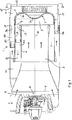
- The invention is described below in more detail on the basis of embodiment examples with reference to the attached drawings, in which
- Fig. 1
- is a schematic longitudinal section through an arrangement according to a first embodiment of the present invention,
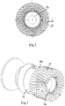
- Fig. 2
- is a view along the line II-II in
Fig. 1 , - Fig. 3
- is a perspective view of constituent parts of the arrangement according to
Fig. 1 , - Fig. 4
- is a schematic longitudinal section through an arrangement according to a second embodiment of the present invention,
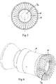
- Fig. 5
- is a view along the line V-V in
Fig. 4 , and - Fig. 6
- is a perspective view of constituent parts of the arrangement according to
Fig. 4 . -
Figs. 1-6 illustrate an arrangement 1 according to two different embodiments of the present invention for introducing a liquid medium into exhaust gases from a combustion engine. The arrangement may for example be situated in an exhaust line upstream of an SCR catalyst in order to introduce a liquid reducing agent in the form of urea or ammonia into the exhaust line upstream of the SCR catalyst, or be situated in an exhaust post-treatment device in order to introduce a liquid reducing agent in the form of urea or ammonia upstream of an SCR catalyst which forms part of the exhaust post-treatment device. - The arrangement 1 comprises a
mixing chamber 3 intended to receive exhaust gases from a combustion engine and lead them towards an exhaust post-treatment unit, e.g. in the form of an SCR catalyst. Themixing chamber 3 is thus intended to have exhaust gases flow through it. The mixing chamber has an upstream end 4 and adownstream end 5. The mixing chamber is delineated in the axial direction by an endwall 7 at itsdownstream end 5. The mixing chamber is further delineated in radial directions by atubular wall 6, which extends between the injection chamber's upstream end 4 anddownstream end 5. The mixing chamber has an inlet 8 to receive exhaust gases at its upstream end and an outlet 9 to release exhaust gases at its downstream end. The outlet 9 is situated at the end of thetubular wall 6 between thistubular wall 6 and the periphery of the endwall 7. The outlet 9 is with advantage annular and adapted to extending round the mixing chamber'scentreline 10. The inlet 8 is likewise with advantage annular and adapted to extending round the mixing chamber'scentreline 10. - In the embodiments depicted, the endwall 7 is provided with a middle portion 7a and an
annular edge portion 7b which surrounds the middle portion. The side of the middle portion 7a which faces towards the mixingchamber 3 is with advantage of convex shape as illustrated inFigs. 1 and4 . The side of the endwall'sedge portion 7b which faces towards the mixingchamber 3 serves as a guide surface 11 which is rounded to guide the exhaust gases flowing towards the endwall 7 to flow towards the mixing chamber's outlet 9 by reversal of their direction of flow. - An injection means 12 for injecting the liquid medium is situated at the centre of the mixing chamber's upstream end 4 to inject the liquid medium towards the mixing chamber's
downstream end 5. The injection means 12, which may for example comprise an injection nozzle, is adapted to injecting the liquid medium into the mixingchamber 3 in finely divided spray form under pressure. - The arrangement 1 further comprises an
exhaust passage 13 situated adjacent to and downstream of the mixingchamber 3. This exhaust passage is intended to have exhaust gases flow through it and is delineated from the mixing chamber by the aforesaid endwall 7.Heat flanges 14 of thermally conductive material are provided on at least part of the side of the endwall 7, which faces towards saidexhaust passage 13. These heat flanges are in heat-transferring contact with the endwall 7. They extend into theexhaust passage 13 and are adapted to absorbing heat from exhaust gases which flow through the exhaust passage and to giving off this heat to the endwall 7 to warm its surfaces which face in towards the mixing chamber. The endwall 7 and theheat flanges 14 are with advantage made of metal material with good thermal conductivity. In the embodiments depicted, the heat flanges abut against the endwall'sannular edge portion 7b, whereas the middle portion 7a is free from heat flanges. The flanges are distributed in the circumferential direction of the endwall'sannular edge portion 7b. In the embodiment depicted inFigs. 1-3 , they extend in the endwall's radial direction. Theexhaust passage 13 is surrounded by atubular wall 15 and theheat flanges 14 are spaced from thistubular wall 15 to avoid conducting heat to it. - In the embodiments depicted, the mixing
chamber 3 is connected to theexhaust passage 13 via anexhaust duct 16, which has anannular inlet 17 to receive exhaust gases from the mixing chamber, and anoutlet 18 leading to the exhaust passage's upper end to deliver exhaust gases to the exhaust passage. Theexhaust duct outlet 18 is annular and extends round the endwall'sedge portion 7b. The exhaust duct comprises a first duct portion 16a which is annular in cross-section and which has theexhaust duct inlet 17 situated at its upstream end. The exhaust duct comprises also a second duct portion 16b which is annular in cross-section and situated downstream of the first duct portion 16a. Theexhaust duct outlet 18 is situated at the downstream end of this second duct portion 16b. The first duct portion 16a surrounds and is concentric with the mixing chamber. The second duct portion 16b surrounds and is concentric with the first duct portion 16a. The second duct portion 16b is connected to the first duct portion 16a via aflow reversal portion 16c which is part of the exhaust duct and which is adapted to reversing the direction of flow of the exhaust gases flowing through the exhaust duct so that they are caused to flow through the second duct portion 16b in a direction opposite to that of their flow in the first duct portion 16a. In the first duct portion 16a, the exhaust gases flow in a direction opposite to that of their flow in the mixing chamber. - The mixing chamber is delineated from the exhaust duct's first duct portion 16a by the aforesaid
tubular wall 6. The first duct portion 16a of the exhaust duct extends on the outside of this tubular wall. The first and second duct portions 16a, 16b of the exhaust duct are themselves delineated from one another by atubular separating wall 19, which is situated externally to saidwall 6 and serves as an inner wall of the second duct portion 16b. The second duct portion 16b is delineated in radial directions by atubular wall 20 situated externally about the separatingwall 19 and serving as an outer wall of the second duct portion 16b. The separatingwall 19 is connected to the endwall'sedge portion 7b, whereas thetubular wall 20 is connected to the aforesaidtubular wall 15 of theexhaust passage 13. - The spray of liquid medium injected into the mixing
chamber 3 via the injection means 12 comes into contact in the mixing chamber with exhaust gases which flow into the chamber via its inlet 8 in a substantially symmetrically flow round this spray. The exhaust gases flowing into the mixing chamber carry the liquid medium with them downstream in the mixing chamber. During its movement downstream in the mixing chamber, the liquid medium spreads out into the exhaust gases and part of it is vaporised by their heat. Liquid medium, which does not vaporise while moving through the mixing chamber, reaches the endwall 7 at the chamber'sdownstream end 5. The liquid medium, which reaches this endwall 7, will be vaporised by the hot exhaust gases. From the mixing chamber the exhaust gases proceed via theexhaust duct 16 to theexhaust passage 13. When entering the exhaust passage, they flow along and give off heat to theheat flanges 14. The flanges pass this heat on to the endwall 7. - In the embodiment depicted in
Figs. 1-3 , the heat flanges are provided withflange portions 14a, which extend into the aforesaid second duct portion 16b of the exhaust duct. These flange portions extend in the longitudinal direction of the second duct portion 16b. They are situated between the tubularinner wall 19 and the tubularouter wall 20 of the second duct portion 16b and are spaced from both theinner wall 19 and theouter wall 20 to avoid conducting heat to them. The heat flanges 14 are thus not in heat-transferring contact with thetubular walls - The arrangement according to the invention is particularly intended for use in a heavy motor vehicle, e.g. a bus, a tractor vehicle or a truck.
- The invention is of course in no way restricted to the embodiments described above, since many possibilities for modifications thereof are likely to be obvious to one skilled in the art without having to deviate from the invention's basic concept such as defined in the attached claims.
Claims (9)
- An arrangement for introducing a liquid medium, e.g. urea, into exhaust gases from a combustion engine, which arrangement (1) comprises- a mixing chamber (3) which is intended to have exhaust gases flow through it and which has at its downstream end (5) an endwall (7) of thermally conductive material which serves as an end surface of the mixing chamber (3),- an injection means (12) for injecting the liquid medium in spray form into the mixing chamber (3) or into exhaust gases which are led into the mixing chamber (3),- an exhaust passage which is adjacent to the mixing chamber (3), and which is intended to have exhaust gases flow through it and is delineated from the mixing chamber (3) by said endwall (7), characterised in that heat flanges (14) of thermally conductive material situated on at least part of the side of said endwall (7) which faces towards said exhaust passage (13) extend into the exhaust passage (13) and are adapted to absorb heat from exhaust gases which flow through the exhaust passage and to give off this heat to the endwall (7),hat said exhaust passage (13) is connected to a tubular duct portion (16b) of an exhaust duct (16) which is adapted to lead exhaust gases to the exhaust passage (13), which tubular duct portion (16b) is delineated in radial directions inwards by a tubular inner wall (19) which is connected to said endwall (7), and that at least some of the said heat flanges (14) are provided with flange portions (14a) which extend into said tubular duct portion (16b).t
- An arrangement according to claim 1, characterised in that said exhaust passage (13) is surrounded by a tubular wall (15), said heat flanges (14) being situated at a distance from this tubular wall (15).
- An arrangement according to claim 1 or 2, characterised in that said flange portions (14a) are situated at a distance from said tubular inner wall (19).
- An arrangement according to claim 1 or 3, characterised in that said tubular duct portion (16b) is delineated in radial directions outwards by a tubular outer wall (20) situated externally about said tubular inner wall (19), said flange portions (14a) being situated between the tubular inner wall (19) and the tubular outer wall (20) and at a distance from the tubular outer wall (20).
- An arrangement according to claim 4 in combination with claim 2, characterised in that said tubular outer wall (20) of the tubular duct portion (16b) is connected to said tubular wall (15) of the exhaust passage (13).
- An arrangement according to any one of claims 1-5, characterised in that said heat flanges (14) are situated on an annular portion (7b) of said endwall (7) and are distributed in the circumferential direction of said annular portion (7b).
- An arrangement according to any one of claims 1-6, characterised in that said exhaust passage (13) is situated downstream of the mixing chamber (3).
- An arrangement according to any one of claims 1-7, characterised in that the injection means (12) is situated at the centre of the mixing chamber's upstream end (4) and is adapted to injecting the liquid medium towards the mixing chamber's downstream end (5).
- An arrangement according to any one of claims 1-8, characterised in that said end wall (7) and heat flanges (14) are made of metal.
Applications Claiming Priority (2)
| Application Number | Priority Date | Filing Date | Title |
|---|---|---|---|
| SE1150875A SE536062C2 (en) | 2011-09-26 | 2011-09-26 | Arrangements equipped with heat transfer flanges for introducing a liquid medium into exhaust gases from an internal combustion engine |
| PCT/SE2012/050957 WO2013048309A1 (en) | 2011-09-26 | 2012-09-12 | Arrangement for introducing a liquid medium into exhaust gases from a combustion engine |
Publications (3)
| Publication Number | Publication Date |
|---|---|
| EP2761148A1 EP2761148A1 (en) | 2014-08-06 |
| EP2761148A4 EP2761148A4 (en) | 2015-06-17 |
| EP2761148B1 true EP2761148B1 (en) | 2017-05-10 |
Family
ID=47996081
Family Applications (1)
| Application Number | Title | Priority Date | Filing Date |
|---|---|---|---|
| EP12834618.6A Active EP2761148B1 (en) | 2011-09-26 | 2012-09-12 | Arrangement for introducing a liquid medium into exhaust gases from a combustion engine |
Country Status (10)
| Country | Link |
|---|---|
| US (1) | US9103258B2 (en) |
| EP (1) | EP2761148B1 (en) |
| JP (1) | JP2014526653A (en) |
| KR (1) | KR101907133B1 (en) |
| CN (1) | CN103827458B (en) |
| BR (1) | BR112014007165B1 (en) |
| DK (1) | DK2761148T3 (en) |
| RU (1) | RU2563440C1 (en) |
| SE (1) | SE536062C2 (en) |
| WO (1) | WO2013048309A1 (en) |
Cited By (1)
| Publication number | Priority date | Publication date | Assignee | Title |
|---|---|---|---|---|
| US11015507B2 (en) | 2017-10-16 | 2021-05-25 | Eberspächer Exhaust Technology GmbH & Co. KG | Exhaust gas/reactant mixing assembly unit |
Families Citing this family (34)
| Publication number | Priority date | Publication date | Assignee | Title |
|---|---|---|---|---|
| DE202008001547U1 (en) | 2007-07-24 | 2008-04-10 | Emcon Technologies Germany (Augsburg) Gmbh | Assembly for introducing a reducing agent into the exhaust pipe of an exhaust system of an internal combustion engine |
| DE102011015512A1 (en) * | 2011-03-30 | 2012-10-04 | Dif Die Ideenfabrik Gmbh | Compact exhaust treatment unit with mixing zone and method for mixing an exhaust gas |
| SE536832C2 (en) * | 2012-12-21 | 2014-09-23 | Scania Cv Ab | Arrangement for introducing a liquid medium into exhaust gases from an internal combustion engine |
| US9314750B2 (en) | 2013-05-07 | 2016-04-19 | Tenneco Automotive Operating Company Inc. | Axial flow atomization module |
| US9289724B2 (en) | 2013-05-07 | 2016-03-22 | Tenneco Automotive Operating Company Inc. | Flow reversing exhaust gas mixer |
| US9364790B2 (en) | 2013-05-07 | 2016-06-14 | Tenneco Automotive Operating Company Inc. | Exhaust mixing assembly |
| US9291081B2 (en) | 2013-05-07 | 2016-03-22 | Tenneco Automotive Operating Company Inc. | Axial flow atomization module |
| US9352276B2 (en) | 2013-05-07 | 2016-05-31 | Tenneco Automotive Operating Company Inc. | Exhaust mixing device |
| US9334781B2 (en) | 2013-05-07 | 2016-05-10 | Tenneco Automotive Operating Company Inc. | Vertical ultrasonic decomposition pipe |
| CN104289151A (en) * | 2013-07-17 | 2015-01-21 | 东莞市振华新能源科技有限公司 | Self-cooling stirring shaft of a lithium-ion battery slurry mixer |
| US9616383B2 (en) * | 2014-02-06 | 2017-04-11 | Johnson Matthey Catalysts (Germany) Gmbh | Compact selective catalytic reduction system for nitrogen oxide reduction in the oxygen-rich exhaust of 500 to 4500 kW internal combustion engines |
| WO2015136263A1 (en) * | 2014-03-11 | 2015-09-17 | Johnson Matthey Catalysts (Germany) Gmbh | Compact selective catalytic reduction system for nitrogen oxide reduction in the oxygen-rich exhaust of 500 to 4500 kw internal combustion engines |
| EP3152419B1 (en) | 2014-06-03 | 2020-03-04 | Faurecia Emissions Control Technologies, USA, LLC | Doser cone assembly |
| DE112015004192T5 (en) * | 2014-09-15 | 2017-06-01 | Tenneco Automotive Operating Company Inc. | Exhaust gas mixing arrangement |
| US9726064B2 (en) | 2015-04-30 | 2017-08-08 | Faurecia Emissions Control Technologies, Usa, Llc | Mixer for use in a vehicle exhaust system |
| US9828897B2 (en) | 2015-04-30 | 2017-11-28 | Faurecia Emissions Control Technologies Usa, Llc | Mixer for a vehicle exhaust system |
| US9719397B2 (en) | 2015-04-30 | 2017-08-01 | Faurecia Emissions Control Technologies Usa, Llc | Mixer with integrated doser cone |
| US9714598B2 (en) | 2015-04-30 | 2017-07-25 | Faurecia Emissions Control Technologies, Usa, Llc | Mixer with integrated doser cone |
| US9534525B2 (en) | 2015-05-27 | 2017-01-03 | Tenneco Automotive Operating Company Inc. | Mixer assembly for exhaust aftertreatment system |
| DE102016003739A1 (en) * | 2016-03-31 | 2017-10-05 | Man Diesel & Turbo Se | Exhaust after treatment system and internal combustion engine |
| JP6818884B2 (en) | 2016-10-21 | 2021-01-20 | フォルシア エミッションズ コントロール テクノロジーズ ユーエスエー エルエルシー | Reducing agent mixer |
| CN110573705B (en) | 2017-02-20 | 2022-04-01 | 沃尔沃遍达公司 | Mixer tank, use of a mixer tank and method for mixing |
| CN108457726B (en) | 2017-02-20 | 2024-09-17 | 天纳克(苏州)排放系统有限公司 | Tail gas aftertreatment device |
| US10337380B2 (en) | 2017-07-07 | 2019-07-02 | Faurecia Emissions Control Technologies, Usa, Llc | Mixer for a vehicle exhaust system |
| CN111033006A (en) * | 2017-08-30 | 2020-04-17 | 佛吉亚排放控制技术美国有限公司 | Venturi type ejector cone |
| CN109915236B (en) * | 2017-12-13 | 2024-10-22 | 天纳克(苏州)排放系统有限公司 | Tail gas aftertreatment mixing arrangement |
| US10316721B1 (en) | 2018-04-23 | 2019-06-11 | Faurecia Emissions Control Technologies, Usa, Llc | High efficiency mixer for vehicle exhaust system |
| US10287948B1 (en) | 2018-04-23 | 2019-05-14 | Faurecia Emissions Control Technologies, Usa, Llc | High efficiency mixer for vehicle exhaust system |
| US10787946B2 (en) | 2018-09-19 | 2020-09-29 | Faurecia Emissions Control Technologies, Usa, Llc | Heated dosing mixer |
| DE102019207065B4 (en) * | 2019-05-15 | 2021-05-20 | Vitesco Technologies GmbH | Ring catalyst |
| EP3812557B1 (en) * | 2019-10-22 | 2023-01-25 | Purem GmbH | Mixer |
| EP4396450A1 (en) | 2021-08-31 | 2024-07-10 | Purem Novi, Inc. | Exhaust aftertreatment apparatus |
| FR3146953A1 (en) * | 2023-03-22 | 2024-09-27 | Faurecia Systemes D'echappement | Reducing fluid mixer for exhaust line |
| CN120845159B (en) * | 2025-09-22 | 2026-02-24 | 福建明泰船舶科技有限公司 | Generating set exhaust emission treatment system |
Family Cites Families (16)
| Publication number | Priority date | Publication date | Assignee | Title |
|---|---|---|---|---|
| US2946651A (en) * | 1956-08-09 | 1960-07-26 | Oxy Catalyst Inc | Catalytic treatment of gas streams |
| DE1208294B (en) * | 1963-02-13 | 1966-01-05 | Gubela Chemie K G | Device for mixing or connecting gaseous, liquid or solid components, in particular liquids |
| FI93138C (en) * | 1992-10-30 | 1995-02-27 | Eero Aitta | Catalytic exhaust gas purifying diesel engine utilizing centrifugal force for particulate separation and catalytic process for exhaust gas purification |
| DE59605314D1 (en) * | 1995-06-28 | 2000-06-29 | Siemens Ag | METHOD AND DEVICE FOR CATALYTICALLY CLEANING THE EXHAUST GAS FROM A COMBUSTION PLANT |
| US6679052B2 (en) * | 2001-07-31 | 2004-01-20 | Toyota Jidosha Kaisha | Emission control apparatus |
| JP2006515401A (en) | 2003-01-14 | 2006-05-25 | エミテック ゲゼルシヤフト フユア エミツシオンス テクノロギー ミツト ベシユレンクテル ハフツング | Space-saving exhaust gas aftertreatment device that has exhaust and recirculation zones located in a nested manner and that allows exhaust gas to flow in and out on the same side |
| US7210287B2 (en) * | 2004-03-24 | 2007-05-01 | General Motors Corporation | Accelerating catalytic conversion |
| EP1801372B1 (en) * | 2005-12-22 | 2011-03-30 | ARK-Holding AG | Particulate filter arrangement und exhaust gas filtering method |
| GB0606116D0 (en) * | 2006-03-28 | 2006-05-03 | Arvinmeritor A & Et Ltd | A mixing chamber for an exhaust system |
| JP4767909B2 (en) * | 2007-06-04 | 2011-09-07 | ヤンマー株式会社 | Exhaust gas purification device |
| FR2925583A3 (en) | 2007-12-21 | 2009-06-26 | Renault Sas | DEVICE FOR DEPOLLUTING THE EXHAUST GASES OF AN INTERNAL COMBUSTION ENGINE |
| US20100139258A1 (en) * | 2008-12-04 | 2010-06-10 | Caterpillar Inc. | Exhaust mixer with backward flow |
| FR2945576A1 (en) * | 2009-05-14 | 2010-11-19 | Peugeot Citroen Automobiles Sa | Mixer for mixing fuel e.g. diesel, injected into exhaust line with exhaust gas produced by internal combustion of car, has deflector whose length along path is greater or equal to half of large transverse dimension of inner periphery |
| JP2011012564A (en) * | 2009-06-30 | 2011-01-20 | Toyota Industries Corp | Exhaust gas purification apparatus |
| DE102009036511B4 (en) * | 2009-08-07 | 2023-11-09 | Friedrich Boysen Gmbh & Co. Kg | Exhaust system |
| US8291696B2 (en) * | 2009-10-13 | 2012-10-23 | International Engine Intellectual Property Company, Llc | SCR mixer |
-
2011
- 2011-09-26 SE SE1150875A patent/SE536062C2/en unknown
-
2012
- 2012-09-12 JP JP2014531762A patent/JP2014526653A/en active Pending
- 2012-09-12 DK DK12834618.6T patent/DK2761148T3/en active
- 2012-09-12 US US14/346,978 patent/US9103258B2/en not_active Expired - Fee Related
- 2012-09-12 WO PCT/SE2012/050957 patent/WO2013048309A1/en not_active Ceased
- 2012-09-12 EP EP12834618.6A patent/EP2761148B1/en active Active
- 2012-09-12 RU RU2014116965/06A patent/RU2563440C1/en active
- 2012-09-12 CN CN201280046598.7A patent/CN103827458B/en active Active
- 2012-09-12 BR BR112014007165-9A patent/BR112014007165B1/en active IP Right Grant
- 2012-09-12 KR KR1020147011299A patent/KR101907133B1/en active Active
Cited By (1)
| Publication number | Priority date | Publication date | Assignee | Title |
|---|---|---|---|---|
| US11015507B2 (en) | 2017-10-16 | 2021-05-25 | Eberspächer Exhaust Technology GmbH & Co. KG | Exhaust gas/reactant mixing assembly unit |
Also Published As
| Publication number | Publication date |
|---|---|
| US9103258B2 (en) | 2015-08-11 |
| KR101907133B1 (en) | 2018-10-11 |
| US20140311133A1 (en) | 2014-10-23 |
| BR112014007165B1 (en) | 2021-03-23 |
| RU2563440C1 (en) | 2015-09-20 |
| WO2013048309A1 (en) | 2013-04-04 |
| DK2761148T3 (en) | 2017-08-28 |
| JP2014526653A (en) | 2014-10-06 |
| KR20140082753A (en) | 2014-07-02 |
| CN103827458A (en) | 2014-05-28 |
| SE536062C2 (en) | 2013-04-23 |
| SE1150875A1 (en) | 2013-03-27 |
| EP2761148A4 (en) | 2015-06-17 |
| EP2761148A1 (en) | 2014-08-06 |
| CN103827458B (en) | 2016-02-03 |
| BR112014007165A2 (en) | 2017-04-04 |
Similar Documents
| Publication | Publication Date | Title |
|---|---|---|
| US9103258B2 (en) | Arrangement for introducing a liquid medium into exhaust combustion engine | |
| EP2630350B1 (en) | Arrangement for introducing a liquid medium into exhaust gases from a combustion engine | |
| US8899026B2 (en) | Arrangement for introducing a liquid medium into exhaust gases from a combustion engine | |
| EP2625398B1 (en) | Arrangement for introducing a liquid medium into exhaust gases from a combustion engine | |
| EP2622184B1 (en) | Arrangement for introducing a liquid medium into exhaust gases from a combustion engine | |
| RU2609009C2 (en) | Device to feed fluid into internal combustion engine exhaust gases | |
| CN107002539A (en) | Exhaust gas purification part for purifying internal combustion engine exhaust gas | |
| KR101721617B1 (en) | Arrangement to insert a liquid medium into exhausts from a combustion engine | |
| WO2015053683A1 (en) | Arrangement for introducing a liquid medium in exhaust gases from an internal combustion engine |
Legal Events
| Date | Code | Title | Description |
|---|---|---|---|
| PUAI | Public reference made under article 153(3) epc to a published international application that has entered the european phase |
Free format text: ORIGINAL CODE: 0009012 |
|
| 17P | Request for examination filed |
Effective date: 20140428 |
|
| AK | Designated contracting states |
Kind code of ref document: A1 Designated state(s): AL AT BE BG CH CY CZ DE DK EE ES FI FR GB GR HR HU IE IS IT LI LT LU LV MC MK MT NL NO PL PT RO RS SE SI SK SM TR |
|
| DAX | Request for extension of the european patent (deleted) | ||
| RA4 | Supplementary search report drawn up and despatched (corrected) |
Effective date: 20150520 |
|
| RIC1 | Information provided on ipc code assigned before grant |
Ipc: F01N 3/20 20060101AFI20150513BHEP Ipc: B01F 15/06 20060101ALI20150513BHEP Ipc: B01F 3/04 20060101ALI20150513BHEP Ipc: B01F 5/06 20060101ALI20150513BHEP Ipc: F01N 5/02 20060101ALI20150513BHEP |
|
| GRAP | Despatch of communication of intention to grant a patent |
Free format text: ORIGINAL CODE: EPIDOSNIGR1 |
|
| INTG | Intention to grant announced |
Effective date: 20161213 |
|
| GRAS | Grant fee paid |
Free format text: ORIGINAL CODE: EPIDOSNIGR3 |
|
| GRAA | (expected) grant |
Free format text: ORIGINAL CODE: 0009210 |
|
| AK | Designated contracting states |
Kind code of ref document: B1 Designated state(s): AL AT BE BG CH CY CZ DE DK EE ES FI FR GB GR HR HU IE IS IT LI LT LU LV MC MK MT NL NO PL PT RO RS SE SI SK SM TR |
|
| REG | Reference to a national code |
Ref country code: GB Ref legal event code: FG4D |
|
| REG | Reference to a national code |
Ref country code: AT Ref legal event code: REF Ref document number: 892584 Country of ref document: AT Kind code of ref document: T Effective date: 20170515 Ref country code: CH Ref legal event code: EP |
|
| REG | Reference to a national code |
Ref country code: IE Ref legal event code: FG4D |
|
| REG | Reference to a national code |
Ref country code: DE Ref legal event code: R096 Ref document number: 602012032370 Country of ref document: DE |
|
| REG | Reference to a national code |
Ref country code: FR Ref legal event code: PLFP Year of fee payment: 6 |
|
| REG | Reference to a national code |
Ref country code: DK Ref legal event code: T3 Effective date: 20170822 |
|
| REG | Reference to a national code |
Ref country code: NL Ref legal event code: MP Effective date: 20170510 |
|
| REG | Reference to a national code |
Ref country code: LT Ref legal event code: MG4D |
|
| REG | Reference to a national code |
Ref country code: AT Ref legal event code: MK05 Ref document number: 892584 Country of ref document: AT Kind code of ref document: T Effective date: 20170510 |
|
| PG25 | Lapsed in a contracting state [announced via postgrant information from national office to epo] |
Ref country code: FI Free format text: LAPSE BECAUSE OF FAILURE TO SUBMIT A TRANSLATION OF THE DESCRIPTION OR TO PAY THE FEE WITHIN THE PRESCRIBED TIME-LIMIT Effective date: 20170510 Ref country code: NO Free format text: LAPSE BECAUSE OF FAILURE TO SUBMIT A TRANSLATION OF THE DESCRIPTION OR TO PAY THE FEE WITHIN THE PRESCRIBED TIME-LIMIT Effective date: 20170810 Ref country code: AT Free format text: LAPSE BECAUSE OF FAILURE TO SUBMIT A TRANSLATION OF THE DESCRIPTION OR TO PAY THE FEE WITHIN THE PRESCRIBED TIME-LIMIT Effective date: 20170510 Ref country code: HR Free format text: LAPSE BECAUSE OF FAILURE TO SUBMIT A TRANSLATION OF THE DESCRIPTION OR TO PAY THE FEE WITHIN THE PRESCRIBED TIME-LIMIT Effective date: 20170510 Ref country code: LT Free format text: LAPSE BECAUSE OF FAILURE TO SUBMIT A TRANSLATION OF THE DESCRIPTION OR TO PAY THE FEE WITHIN THE PRESCRIBED TIME-LIMIT Effective date: 20170510 Ref country code: ES Free format text: LAPSE BECAUSE OF FAILURE TO SUBMIT A TRANSLATION OF THE DESCRIPTION OR TO PAY THE FEE WITHIN THE PRESCRIBED TIME-LIMIT Effective date: 20170510 Ref country code: GR Free format text: LAPSE BECAUSE OF FAILURE TO SUBMIT A TRANSLATION OF THE DESCRIPTION OR TO PAY THE FEE WITHIN THE PRESCRIBED TIME-LIMIT Effective date: 20170811 |
|
| PG25 | Lapsed in a contracting state [announced via postgrant information from national office to epo] |
Ref country code: BG Free format text: LAPSE BECAUSE OF FAILURE TO SUBMIT A TRANSLATION OF THE DESCRIPTION OR TO PAY THE FEE WITHIN THE PRESCRIBED TIME-LIMIT Effective date: 20170810 Ref country code: IS Free format text: LAPSE BECAUSE OF FAILURE TO SUBMIT A TRANSLATION OF THE DESCRIPTION OR TO PAY THE FEE WITHIN THE PRESCRIBED TIME-LIMIT Effective date: 20170910 Ref country code: PL Free format text: LAPSE BECAUSE OF FAILURE TO SUBMIT A TRANSLATION OF THE DESCRIPTION OR TO PAY THE FEE WITHIN THE PRESCRIBED TIME-LIMIT Effective date: 20170510 Ref country code: RS Free format text: LAPSE BECAUSE OF FAILURE TO SUBMIT A TRANSLATION OF THE DESCRIPTION OR TO PAY THE FEE WITHIN THE PRESCRIBED TIME-LIMIT Effective date: 20170510 Ref country code: SE Free format text: LAPSE BECAUSE OF FAILURE TO SUBMIT A TRANSLATION OF THE DESCRIPTION OR TO PAY THE FEE WITHIN THE PRESCRIBED TIME-LIMIT Effective date: 20170510 Ref country code: NL Free format text: LAPSE BECAUSE OF FAILURE TO SUBMIT A TRANSLATION OF THE DESCRIPTION OR TO PAY THE FEE WITHIN THE PRESCRIBED TIME-LIMIT Effective date: 20170510 |
|
| PG25 | Lapsed in a contracting state [announced via postgrant information from national office to epo] |
Ref country code: RO Free format text: LAPSE BECAUSE OF FAILURE TO SUBMIT A TRANSLATION OF THE DESCRIPTION OR TO PAY THE FEE WITHIN THE PRESCRIBED TIME-LIMIT Effective date: 20170510 Ref country code: CZ Free format text: LAPSE BECAUSE OF FAILURE TO SUBMIT A TRANSLATION OF THE DESCRIPTION OR TO PAY THE FEE WITHIN THE PRESCRIBED TIME-LIMIT Effective date: 20170510 Ref country code: EE Free format text: LAPSE BECAUSE OF FAILURE TO SUBMIT A TRANSLATION OF THE DESCRIPTION OR TO PAY THE FEE WITHIN THE PRESCRIBED TIME-LIMIT Effective date: 20170510 Ref country code: SK Free format text: LAPSE BECAUSE OF FAILURE TO SUBMIT A TRANSLATION OF THE DESCRIPTION OR TO PAY THE FEE WITHIN THE PRESCRIBED TIME-LIMIT Effective date: 20170510 |
|
| REG | Reference to a national code |
Ref country code: DE Ref legal event code: R097 Ref document number: 602012032370 Country of ref document: DE |
|
| PG25 | Lapsed in a contracting state [announced via postgrant information from national office to epo] |
Ref country code: SM Free format text: LAPSE BECAUSE OF FAILURE TO SUBMIT A TRANSLATION OF THE DESCRIPTION OR TO PAY THE FEE WITHIN THE PRESCRIBED TIME-LIMIT Effective date: 20170510 |
|
| PLBE | No opposition filed within time limit |
Free format text: ORIGINAL CODE: 0009261 |
|
| STAA | Information on the status of an ep patent application or granted ep patent |
Free format text: STATUS: NO OPPOSITION FILED WITHIN TIME LIMIT |
|
| 26N | No opposition filed |
Effective date: 20180213 |
|
| REG | Reference to a national code |
Ref country code: CH Ref legal event code: PL |
|
| PG25 | Lapsed in a contracting state [announced via postgrant information from national office to epo] |
Ref country code: SI Free format text: LAPSE BECAUSE OF FAILURE TO SUBMIT A TRANSLATION OF THE DESCRIPTION OR TO PAY THE FEE WITHIN THE PRESCRIBED TIME-LIMIT Effective date: 20170510 Ref country code: MC Free format text: LAPSE BECAUSE OF FAILURE TO SUBMIT A TRANSLATION OF THE DESCRIPTION OR TO PAY THE FEE WITHIN THE PRESCRIBED TIME-LIMIT Effective date: 20170510 |
|
| REG | Reference to a national code |
Ref country code: IE Ref legal event code: MM4A |
|
| REG | Reference to a national code |
Ref country code: BE Ref legal event code: MM Effective date: 20170930 |
|
| PG25 | Lapsed in a contracting state [announced via postgrant information from national office to epo] |
Ref country code: LU Free format text: LAPSE BECAUSE OF NON-PAYMENT OF DUE FEES Effective date: 20170912 |
|
| PG25 | Lapsed in a contracting state [announced via postgrant information from national office to epo] |
Ref country code: LI Free format text: LAPSE BECAUSE OF NON-PAYMENT OF DUE FEES Effective date: 20170930 Ref country code: CH Free format text: LAPSE BECAUSE OF NON-PAYMENT OF DUE FEES Effective date: 20170930 Ref country code: IE Free format text: LAPSE BECAUSE OF NON-PAYMENT OF DUE FEES Effective date: 20170912 |
|
| REG | Reference to a national code |
Ref country code: FR Ref legal event code: PLFP Year of fee payment: 7 |
|
| PG25 | Lapsed in a contracting state [announced via postgrant information from national office to epo] |
Ref country code: BE Free format text: LAPSE BECAUSE OF NON-PAYMENT OF DUE FEES Effective date: 20170930 |
|
| PG25 | Lapsed in a contracting state [announced via postgrant information from national office to epo] |
Ref country code: MT Free format text: LAPSE BECAUSE OF NON-PAYMENT OF DUE FEES Effective date: 20170912 |
|
| PG25 | Lapsed in a contracting state [announced via postgrant information from national office to epo] |
Ref country code: HU Free format text: LAPSE BECAUSE OF FAILURE TO SUBMIT A TRANSLATION OF THE DESCRIPTION OR TO PAY THE FEE WITHIN THE PRESCRIBED TIME-LIMIT; INVALID AB INITIO Effective date: 20120912 |
|
| PG25 | Lapsed in a contracting state [announced via postgrant information from national office to epo] |
Ref country code: CY Free format text: LAPSE BECAUSE OF NON-PAYMENT OF DUE FEES Effective date: 20170510 |
|
| PG25 | Lapsed in a contracting state [announced via postgrant information from national office to epo] |
Ref country code: MK Free format text: LAPSE BECAUSE OF FAILURE TO SUBMIT A TRANSLATION OF THE DESCRIPTION OR TO PAY THE FEE WITHIN THE PRESCRIBED TIME-LIMIT Effective date: 20170510 |
|
| PG25 | Lapsed in a contracting state [announced via postgrant information from national office to epo] |
Ref country code: TR Free format text: LAPSE BECAUSE OF FAILURE TO SUBMIT A TRANSLATION OF THE DESCRIPTION OR TO PAY THE FEE WITHIN THE PRESCRIBED TIME-LIMIT Effective date: 20170510 |
|
| PG25 | Lapsed in a contracting state [announced via postgrant information from national office to epo] |
Ref country code: PT Free format text: LAPSE BECAUSE OF FAILURE TO SUBMIT A TRANSLATION OF THE DESCRIPTION OR TO PAY THE FEE WITHIN THE PRESCRIBED TIME-LIMIT Effective date: 20170510 |
|
| PG25 | Lapsed in a contracting state [announced via postgrant information from national office to epo] |
Ref country code: AL Free format text: LAPSE BECAUSE OF FAILURE TO SUBMIT A TRANSLATION OF THE DESCRIPTION OR TO PAY THE FEE WITHIN THE PRESCRIBED TIME-LIMIT Effective date: 20170510 |
|
| P01 | Opt-out of the competence of the unified patent court (upc) registered |
Effective date: 20230516 |
|
| PGFP | Annual fee paid to national office [announced via postgrant information from national office to epo] |
Ref country code: DK Payment date: 20250911 Year of fee payment: 14 Ref country code: DE Payment date: 20250730 Year of fee payment: 14 |
|
| PGFP | Annual fee paid to national office [announced via postgrant information from national office to epo] |
Ref country code: IT Payment date: 20250825 Year of fee payment: 14 |
|
| PGFP | Annual fee paid to national office [announced via postgrant information from national office to epo] |
Ref country code: GB Payment date: 20250731 Year of fee payment: 14 |
|
| PGFP | Annual fee paid to national office [announced via postgrant information from national office to epo] |
Ref country code: FR Payment date: 20250808 Year of fee payment: 14 |
|
| PGFP | Annual fee paid to national office [announced via postgrant information from national office to epo] |
Ref country code: LV Payment date: 20250805 Year of fee payment: 14 |