EP2760790B1 - Chemical looping removal of ventilation air methane - Google Patents
Chemical looping removal of ventilation air methane Download PDFInfo
- Publication number
- EP2760790B1 EP2760790B1 EP12836598.8A EP12836598A EP2760790B1 EP 2760790 B1 EP2760790 B1 EP 2760790B1 EP 12836598 A EP12836598 A EP 12836598A EP 2760790 B1 EP2760790 B1 EP 2760790B1
- Authority
- EP
- European Patent Office
- Prior art keywords
- particles
- methane
- section
- reactor
- ventilation air
- Prior art date
- Legal status (The legal status is an assumption and is not a legal conclusion. Google has not performed a legal analysis and makes no representation as to the accuracy of the status listed.)
- Not-in-force
Links
Images



Classifications
-
- B—PERFORMING OPERATIONS; TRANSPORTING
- B01—PHYSICAL OR CHEMICAL PROCESSES OR APPARATUS IN GENERAL
- B01D—SEPARATION
- B01D53/00—Separation of gases or vapours; Recovering vapours of volatile solvents from gases; Chemical or biological purification of waste gases, e.g. engine exhaust gases, smoke, fumes, flue gases, aerosols
- B01D53/34—Chemical or biological purification of waste gases
- B01D53/74—General processes for purification of waste gases; Apparatus or devices specially adapted therefor
- B01D53/86—Catalytic processes
- B01D53/8668—Removing organic compounds not provided for in B01D53/8603 - B01D53/8665
-
- B—PERFORMING OPERATIONS; TRANSPORTING
- B01—PHYSICAL OR CHEMICAL PROCESSES OR APPARATUS IN GENERAL
- B01D—SEPARATION
- B01D53/00—Separation of gases or vapours; Recovering vapours of volatile solvents from gases; Chemical or biological purification of waste gases, e.g. engine exhaust gases, smoke, fumes, flue gases, aerosols
- B01D53/34—Chemical or biological purification of waste gases
- B01D53/46—Removing components of defined structure
- B01D53/72—Organic compounds not provided for in groups B01D53/48 - B01D53/70, e.g. hydrocarbons
-
- C—CHEMISTRY; METALLURGY
- C01—INORGANIC CHEMISTRY
- C01B—NON-METALLIC ELEMENTS; COMPOUNDS THEREOF; METALLOIDS OR COMPOUNDS THEREOF NOT COVERED BY SUBCLASS C01C
- C01B3/00—Hydrogen; Gaseous mixtures containing hydrogen; Separation of hydrogen from mixtures containing it; Purification of hydrogen; Reversible storage of hydrogen
- C01B3/02—Production of hydrogen; Production of gaseous mixtures containing hydrogen
- C01B3/06—Production of hydrogen; Production of gaseous mixtures containing hydrogen by reaction of inorganic compounds containing electro-positively bound hydrogen with inorganic reducing agents
- C01B3/08—Production of hydrogen; Production of gaseous mixtures containing hydrogen by reaction of inorganic compounds containing electro-positively bound hydrogen with inorganic reducing agents by reaction of inorganic compounds with metals
- C01B3/10—Production of hydrogen; Production of gaseous mixtures containing hydrogen by reaction of inorganic compounds containing electro-positively bound hydrogen with inorganic reducing agents by reaction of inorganic compounds with metals by reaction of water vapour with metals
-
- C—CHEMISTRY; METALLURGY
- C01—INORGANIC CHEMISTRY
- C01B—NON-METALLIC ELEMENTS; COMPOUNDS THEREOF; METALLOIDS OR COMPOUNDS THEREOF NOT COVERED BY SUBCLASS C01C
- C01B32/00—Carbon; Compounds thereof
- C01B32/50—Carbon dioxide
-
- B—PERFORMING OPERATIONS; TRANSPORTING
- B01—PHYSICAL OR CHEMICAL PROCESSES OR APPARATUS IN GENERAL
- B01D—SEPARATION
- B01D2251/00—Reactants
- B01D2251/20—Reductants
-
- B—PERFORMING OPERATIONS; TRANSPORTING
- B01—PHYSICAL OR CHEMICAL PROCESSES OR APPARATUS IN GENERAL
- B01D—SEPARATION
- B01D2255/00—Catalysts
- B01D2255/20—Metals or compounds thereof
- B01D2255/207—Transition metals
- B01D2255/20738—Iron
-
- B—PERFORMING OPERATIONS; TRANSPORTING
- B01—PHYSICAL OR CHEMICAL PROCESSES OR APPARATUS IN GENERAL
- B01D—SEPARATION
- B01D2255/00—Catalysts
- B01D2255/20—Metals or compounds thereof
- B01D2255/207—Transition metals
- B01D2255/20761—Copper
-
- B—PERFORMING OPERATIONS; TRANSPORTING
- B01—PHYSICAL OR CHEMICAL PROCESSES OR APPARATUS IN GENERAL
- B01D—SEPARATION
- B01D2257/00—Components to be removed
- B01D2257/70—Organic compounds not provided for in groups B01D2257/00 - B01D2257/602
- B01D2257/702—Hydrocarbons
- B01D2257/7022—Aliphatic hydrocarbons
- B01D2257/7025—Methane
-
- Y—GENERAL TAGGING OF NEW TECHNOLOGICAL DEVELOPMENTS; GENERAL TAGGING OF CROSS-SECTIONAL TECHNOLOGIES SPANNING OVER SEVERAL SECTIONS OF THE IPC; TECHNICAL SUBJECTS COVERED BY FORMER USPC CROSS-REFERENCE ART COLLECTIONS [XRACs] AND DIGESTS
- Y02—TECHNOLOGIES OR APPLICATIONS FOR MITIGATION OR ADAPTATION AGAINST CLIMATE CHANGE
- Y02C—CAPTURE, STORAGE, SEQUESTRATION OR DISPOSAL OF GREENHOUSE GASES [GHG]
- Y02C20/00—Capture or disposal of greenhouse gases
- Y02C20/20—Capture or disposal of greenhouse gases of methane
-
- Y—GENERAL TAGGING OF NEW TECHNOLOGICAL DEVELOPMENTS; GENERAL TAGGING OF CROSS-SECTIONAL TECHNOLOGIES SPANNING OVER SEVERAL SECTIONS OF THE IPC; TECHNICAL SUBJECTS COVERED BY FORMER USPC CROSS-REFERENCE ART COLLECTIONS [XRACs] AND DIGESTS
- Y02—TECHNOLOGIES OR APPLICATIONS FOR MITIGATION OR ADAPTATION AGAINST CLIMATE CHANGE
- Y02E—REDUCTION OF GREENHOUSE GAS [GHG] EMISSIONS, RELATED TO ENERGY GENERATION, TRANSMISSION OR DISTRIBUTION
- Y02E60/00—Enabling technologies; Technologies with a potential or indirect contribution to GHG emissions mitigation
- Y02E60/30—Hydrogen technology
- Y02E60/36—Hydrogen production from non-carbon containing sources, e.g. by water electrolysis
-
- Y—GENERAL TAGGING OF NEW TECHNOLOGICAL DEVELOPMENTS; GENERAL TAGGING OF CROSS-SECTIONAL TECHNOLOGIES SPANNING OVER SEVERAL SECTIONS OF THE IPC; TECHNICAL SUBJECTS COVERED BY FORMER USPC CROSS-REFERENCE ART COLLECTIONS [XRACs] AND DIGESTS
- Y02—TECHNOLOGIES OR APPLICATIONS FOR MITIGATION OR ADAPTATION AGAINST CLIMATE CHANGE
- Y02P—CLIMATE CHANGE MITIGATION TECHNOLOGIES IN THE PRODUCTION OR PROCESSING OF GOODS
- Y02P20/00—Technologies relating to chemical industry
- Y02P20/141—Feedstock
-
- Y—GENERAL TAGGING OF NEW TECHNOLOGICAL DEVELOPMENTS; GENERAL TAGGING OF CROSS-SECTIONAL TECHNOLOGIES SPANNING OVER SEVERAL SECTIONS OF THE IPC; TECHNICAL SUBJECTS COVERED BY FORMER USPC CROSS-REFERENCE ART COLLECTIONS [XRACs] AND DIGESTS
- Y02—TECHNOLOGIES OR APPLICATIONS FOR MITIGATION OR ADAPTATION AGAINST CLIMATE CHANGE
- Y02P—CLIMATE CHANGE MITIGATION TECHNOLOGIES IN THE PRODUCTION OR PROCESSING OF GOODS
- Y02P20/00—Technologies relating to chemical industry
- Y02P20/151—Reduction of greenhouse gas [GHG] emissions, e.g. CO2
- Y02P20/156—Methane [CH4]
Definitions
- This invention relates to the chemical looping removal of ventilation air methane and has been devised particularly, though not solely, for removing methane from ventilation air in coal mines.
- VAM ventilation air methane
- VAM destruction i.e. VAM destruction
- technologies based VAM destruction are technically feasible to mitigate VAM when the methane concentration in air exceeds their minimum requirement and economic performance is not an issue, such systems often need additional fuel for continuous operation. Current estimates suggest that the additional fuel intake may be at least 0.9% to maintain methane concentration at suitable levels for prolonged operations. Examples of VAM mitigation systems based on the destruction strategy are:
- the present invention therefore provides an alternative to these earlier forms of VAM destruction by using the concept of chemical looping for mitigation of VAM.
- the present invention provides a method of removing methane from ventilation air by cycling metal or metal oxide particles in a chemical looping process in one or more reactors where the metal particles are alternately reduced and oxidised, and passing ventilation air through one or more of said reactors to convert the air plus methane into reduced air plus water plus carbon dioxide, wherein there are upper and lower reactors connected by an array of parallel inclined plates forming lamellas, the upper reactor forming an oxidiser section and the lower reactor forming a reducer section, wherein the lamellas provide an internal circulation allowing lighter particles to travel to the upper oxidiser section, while keeping heavier particles in the lower reducer section.
- Also disclosed herein is a method of removing methane from ventilation air including the steps of;
- a gasifier may be embedded in either the combustor or the hydrogen generator.
- the metal oxide is in the form of particles of the iron metal oxide Wuestite, with the oxidised metal oxide being Hematite and the highly oxidised metal oxide being Magnetite.
- Also described herein is a method of removing methane from ventilation air including the steps of:
- a gasifier may be embedded in the hydrogen generator.
- the metal oxides are in the form of particles of iron metal oxide.
- the method of the invention uses upper and lower reactors connected by an array of parallel inclined plates forming lamellas, the upper reactor forming an oxidiser section and the lower reactor forming a reducer section, wherein the lamellas provide an internal circulation allowing lighter particles to travel to the upper oxidiser section, while keeping heavier particles in the lower reducer section.
- the lighter particles comprise Fe 3 O 4 and the heavier particles comprise Fe 2 O 3 .
- lighter particles comprise CuO and the heavier particles comprise Cu.
- a gasifier is embedded in the upper reactor.
- the present invention uses the principal of chemical looping to remove methane (CH 4 ) from ventilation air.
- CH 4 methane
- a given chemical reaction e.g. A + B ⁇ C + D
- a given chemical reaction e.g. A + B ⁇ C + D
- solid intermediates such as metals (Me), metal oxides (MeO) and carbon dioxide scavengers (e.g. CaO).
- Me metals
- MeO metal oxides
- CaO carbon dioxide scavengers
- These intermediates are reduced and regenerated in a cyclic fashion through the progress of the sub-reactions.
- the process is typically carried out by circulation of SI particles via a system of two interconnected reactors (typically fluidised beds) where sub-reactions are executed.
- Chemical looping schemes can be designed in such a manner that the energy and exergy losses of the overall process are minimised while allowing the separation of the undesired products (e.g. CO 2 ) generated from the reactions to be accomplished with ease, yielding an overall efficient and economical process. It is this inherent ability for separation of undesired products, such as CO 2 , which makes the chemical looping process an invaluable tool in low CO 2 emission technologies (e.g. clean coal technologies). Furthermore, the ability to incorporate a diverse range of intermediates (e.g. metal oxides, CO 2 scavengers, etc) provides the chemical looping concept with an unprecedented versatility, enabling it to be used in a wide range of applications.
- a diverse range of intermediates e.g. metal oxides, CO 2 scavengers, etc
- CLRVAM chemical looping removal of ventilation air methane
- the hydrogen based CLRVAM processes comprise three main steps, namely:
- the former leads to a flameless low/medium temperature oxidation process during the combustion of VAM / H 2 mixture while the latter results in a high temperature flaming combustion.
- the 3S-CLRVAM is more complex but has a much lower energy footprint than the 2S-CLRVAM version.
- the CLR-VAM process incorporates a three-step chemical loop to fully integrate the hydrogen production, combustion and regeneration steps ( Figure 2 ). Because of the need for high purity hydrogen, the CLR-VAM process can work best with metals with multiple oxidation states. Among these iron (Fe) is preferred primarily because:
- the main goal in Step 1 is to produce high purity hydrogen.
- the working principle of the chemical looping based process employed in this step is based on the cyclic reduction and oxidation of suitable metal oxides oxygen carrier particles, for example FeO (Wuestite) to Fe 3 O 4 (Magnetite). This is carried out by exchanging the carrier particles between the three interconnected reactors involved in the process (see Figure 2 ).
- Step 2 the mixture of H 2 transferred from the hydrogen generator 1 and the incoming VAM stream 2 are combusted together in a combustor 3 in the presence of metal oxides. This ensures non-flaming oxidation of the fuel mixture at moderate to low temperatures (e.g. 500-600°C). Also, hydrogen is used in Step 2 so that the overall fuel to oxygen ratio (i.e. [H 2 +CH 4 ]/O 2 ) is increased. This ensures the complete combustion of the fuel/air mixture in a robust manner; leading to generation of CO 2 and H 2 O. As shown in Figure 2 , Step 2 is carried out in the presence of fully regenerated metal oxide particles which are at their highest oxidation state (i.e.
- MeO (III) is reduced to the lowest oxidation state for the metal employed in the process (MeO (I)), for example Fe 2 O 3 (Hematite) reduces to FeO (Wuestite) in the case of iron.
- the reduced metal, MeO (I) is then fed back to the hydrogen generator 1.
- Step 2 provides a very effective means of dealing with variations and/or fluctuations in methane concentration. For instance, when methane concentration in VAM is low, addition of H 2 shifts the oxidation process towards full completion. Whilst, for situations where methane concentration in VAM increases to levels close to explosion limit, the flows of H 2 and MeO (III) can be stopped and steam is redirected to the combustor rather than the hydrogen generator. This not only brings the hydrogen production to an end but also significantly dilutes the concentration of the fuel/air mixture in the combustor, ultimately preventing any potential explosion.
- Step 3 the gaseous mixture exiting from the combustor and particles of MeO (II) (e.g. Fe 3 O 4 or Magnetite in the case of iron) from the hydrogen generator are fed into the third reactor (regenerator 4).
- MeO (II) e.g. Fe 3 O 4 or Magnetite in the case of iron
- the metal at its intermediate oxidation state is oxidised by incoming air/steam/CO 2 mixture from the combustor and reaches its highest oxidation state.
- Step 1 hydrogen is generated by chemical looping steam reforming although a metal oxide with reversible reduction/oxidation (redox) properties is preferred (e.g. Co, Mn, Cu).
- redox reversible reduction/oxidation
- the main goal in Step 1 is to produce high purity hydrogen.
- the working principle of the chemical looping based process employed in this step is based on the cyclic reduction and oxidation of suitable metal oxides oxygen carrier particles (e.g. Cu/CuO). This is typically carried out by exchanging the carrier particles between two interconnected fluidised bed reactors.
- Step 2 H 2 is transferred from the hydrogen generator 5 ( Figure 3 ) to the combustor 6 so that the overall fuel to air ratio (i.e. [H 2 +CH 4 ]/air) is increased and brought to levels close to the minimum flammability limit.
- This ensures the complete combustion of the fuel/air mixture in a robust manner; leading to generation of CO 2 and H 2 O and slight reduction in O 2 concentration of the ventilation air (i.e. reduced air).
- This step provides a very effective means of dealing with variations and/or fluctuations in methane concentration. For instance, when methane concentration in VAM is below the lower flammability limit, addition of H 2 shifts the oxidation process towards the generation of a stable flame.
- Step 3 the gaseous mixture exiting from the combustor and the MeO from the hydrogen generator are fed into the third reactor (regenerator 7).
- the reduced air is enriched by decoupling the oxygen from MeO simply by controlling the partial pressure of oxygen. This ensures that the mixture exiting the regenerator only contains normal air, steam and carbon dioxide.
- the steam in the outlet can be separated out by condensation and the resulting water can be reused as make-up water in the steam generation process (not shown in Figure 3 ).
- Figure 4 and Figure 5 show two different three reactor versions with the embedded gasifier shown at 8, while Figure 6 shows a two reactor version with the embedded gasifier shown at 9.
- Non-hydrogen based CLRVAM in a single reactor process as shown in Figure 7 .
- This process operates based on the simultaneous oxidation and reduction of Fe2O3/Fe3O4 in a single reactor 20.
- the reactor can be either fixed- or fluidised-bed although fluidised-bed type reactors provide a more robust operation.
- the process can be interfaced with an embedded gasifier 10 and other unit operations for heat/power generation, and there is no hydrogen involved.
- CLRVAM processes can also be provided using "Lamella Embedded Combined” (LEC) Reactors as shown in Figures 8 to 11 .
- LEC Lane Embedded Combined
- VAM is neutralised simply by redox (reduction/oxidation) reactions of metal oxides such as Fe 2 O 3 /Fe 3 O 4 (or CuO/Cu) and there is no hydrogen involved.
- Heavier particles which are typically at their full oxidation state (MeO) are forced to remain at the bottom of the reactor by the lamellas while lighter particles (typically at a lower oxidation state “Me") are transported through the lamella section up to the top of the reactor.
- the reaction taking place in the bottom section is predominately the reduction of MeO by methane content of the ventilation air while the reaction at the top section is regeneration (i.e. oxidation) of reduced metal (Me) to a higher oxidation state.
- Metal oxide systems of interest for VAM abatement include Fe2O3/Fe3O4 and CuO/Cu.
- the key technical features of VAMCO are:
- the reactor is fitted with a series of inclined plates 11 (so-called lamellas) which divide the reactor into two sections, an oxidiser section 12 and a reducer section 13.
- the lamellas 11 provide an internal circulation allowing lighter particles to travel to the top oxidiser section 12 while preventing heavier particles from moving up, as such keeping them at the bottom reducer section 13.
- the lamellas allow reacting particles to be separated based on their density. As such, in the case of Fe 2 O 3 /Fe 3 O 4 , the heavier Fe 2 O 3 particles will predominately exist at the bottom section 13 while lighter Fe 3 O 4 particles exist at the top section 12. This effectively converts the bottom section into a "reducer" and the top section into an "oxidiser".
- FIG. 9 A further version of the CLRVAM process using lamella embedded reactors is shown in Figure 9 using Cu and CuO between a reducer 14 in the upper section and a regenerator 15 in the lower section, connected by the inclined plate lamellas 16.
- the LEC-based CLRVAM systems are extremely energy efficient and can be self sustaining from methane concentrations of about 0.1 vol% which is much lower than the corresponding figures for conventional VAM mitigation systems. This is partly due to the fact that heat is internally circulated from the oxidiser (where the reactions are always exothermic) to the reducer by hot metal oxide particles as shown in Figure 10 . It is also partly due to the fact that the LEC reactor 17 contains metal oxides which have much higher thermal mass than even brick.
- the LEC reactor can be interfaced with an embedded gasifier 18 to:
- LEC modules can be scaled up to meet any VAM flow rate or methane concentration either through:
- a LEC reactor is inherently very safe for a number of reasons:
Landscapes
- Chemical & Material Sciences (AREA)
- Engineering & Computer Science (AREA)
- Chemical Kinetics & Catalysis (AREA)
- Organic Chemistry (AREA)
- Environmental & Geological Engineering (AREA)
- Health & Medical Sciences (AREA)
- Biomedical Technology (AREA)
- Analytical Chemistry (AREA)
- General Chemical & Material Sciences (AREA)
- Oil, Petroleum & Natural Gas (AREA)
- Inorganic Chemistry (AREA)
- Combustion & Propulsion (AREA)
- General Health & Medical Sciences (AREA)
- Hydrogen, Water And Hydrids (AREA)
- Catalysts (AREA)
- Physical Or Chemical Processes And Apparatus (AREA)
Description
- This invention relates to the chemical looping removal of ventilation air methane and has been devised particularly, though not solely, for removing methane from ventilation air in coal mines.
- Release of fugitive methane (CH4) emissions from ventilation air in coalmines is a major source of greenhouse gas emissions (the greenhouse impact of methane is 21 times greater than that of CO2). Approximately 64% of methane emissions in coalmine operations are the result of ventilation air methane (VAM). There are two alternative strategies for mitigation of VAM in mining operations, namely: (i) utilisation of VAM as an energy source, (ii) destruction of VAM through an oxidation process. To date, the implementation of the former strategy has found to be difficult primarily because:
- the volume of the gas mixture is large (can be as high as 600 m3/s);
- the methane concentration in the mixture is dilute (0.1-1 %V/V), and;
- the concentration of methane and the flow rate of the gas mixture are variable.
- The latter strategy (i.e. VAM destruction) has been found more attractive and easier to adopt. Although technologies based VAM destruction are technically feasible to mitigate VAM when the methane concentration in air exceeds their minimum requirement and economic performance is not an issue, such systems often need additional fuel for continuous operation. Current estimates suggest that the additional fuel intake may be at least 0.9% to maintain methane concentration at suitable levels for prolonged operations. Examples of VAM mitigation systems based on the destruction strategy are:
- TFRR (VOCSIDIZER, MEGTEC)
- CFRR (CANMET)
- CMR, catalytic monolith reactor (CSIRO)
- CLBGT, catalytic lean-burn gas turbine (CSIRO, Ingersol-Rand)
- RLBGT, recuperative lean-burn gas turbine (EDL)
- VAM-RAB, ventilated air methane regenerative after burner (Corkys Pty Ltd)
- A method for chemical-looping combustion of methane is also known from Int. J. Chem. Eng., Vol. 2009, article 710515.
- The present invention therefore provides an alternative to these earlier forms of VAM destruction by using the concept of chemical looping for mitigation of VAM.
- Accordingly, in a broad aspect the present invention provides a method of removing methane from ventilation air by cycling metal or metal oxide particles in a chemical looping process in one or more reactors where the metal particles are alternately reduced and oxidised, and passing ventilation air through one or more of said reactors to convert the air plus methane into reduced air plus water plus carbon dioxide, wherein there are upper and lower reactors connected by an array of parallel inclined plates forming lamellas, the upper reactor forming an oxidiser section and the lower reactor forming a reducer section, wherein the lamellas provide an internal circulation allowing lighter particles to travel to the upper oxidiser section, while keeping heavier particles in the lower reducer section.
- Also disclosed herein is a method of removing methane from ventilation air including the steps of;
- i. generating hydrogen in a hydrogen generator fed with steam and reduced metal oxide to produce hydrogen and oxidised metal oxide,
- ii. combusting the ventilation air in a combustor fed with said hydrogen in the presence of metal oxides to produce a gaseous mixture of air plus water plus carbon dioxide, and
- iii. feeding said gaseous mixture to a regenerator together with the oxidised metal oxide from step i to produce reduced air plus water plus carbon dioxide, and highly oxidised metal oxide which is fed to the combustor for use in step ii.
- A gasifier may be embedded in either the combustor or the hydrogen generator.
- Preferably, the metal oxide is in the form of particles of the iron metal oxide Wuestite, with the oxidised metal oxide being Hematite and the highly oxidised metal oxide being Magnetite.
- Also described herein is a method of removing methane from ventilation air including the steps of:
- i. generating hydrogen in a hydrogen generator fed with steam and exchanging metal oxides with a regenerator in a chemical looping process, and
- ii. combusting the ventilation air in a combustor fed with said hydrogen to produce a gaseous mixture of reduced air plus water plus carbon dioxide which is fed in turn to the regenerator for the reduction of the metal oxides and the emission of air plus water plus carbon dioxide.
- A gasifier may be embedded in the hydrogen generator.
- Preferably the metal oxides are in the form of particles of iron metal oxide.
- The method of the invention uses upper and lower reactors connected by an array of parallel inclined plates forming lamellas, the upper reactor forming an oxidiser section and the lower reactor forming a reducer section, wherein the lamellas provide an internal circulation allowing lighter particles to travel to the upper oxidiser section, while keeping heavier particles in the lower reducer section.
- In one embodiment, the lighter particles comprise Fe3O4 and the heavier particles comprise Fe2O3.
- In an alternative embodiment lighter particles comprise CuO and the heavier particles comprise Cu.
- In one form of the invention a gasifier is embedded in the upper reactor.
- To increase the throughput a plurality of upper and lower reactors each connected by a lamella array are operated in parallel.
-
-
Figure 1 is a schematic representation of the chemical looping concept; -
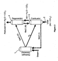
Figure 2 is a schematic representation of a three step ventilation air methane (VAM) removal process; -
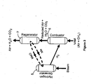
Figure 3 is a schematic representation of a two step ventilation air methane removal process; -
Figure 4 is a schematic representation of the three step VAM shown inFigure 2 , with an embedded gasifier; -
Figure 5 is an alternative version of the three step VAM shown inFigure 4 ; -
Figure 6 is a schematic representation of the two step VAM shown inFigure 3 , with an embedded gasifier; -
Figure 7 is a schematic representation of the VAM in a single reactor process with an embedded gasifier; -
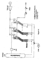
Figure 8 is a schematic representation of a lamella embedded combined (LEC) reactor; -
Figure 9 an alternative version of the LEC shown inFigure 8 ; -
Figure 10 is a schematic representation of a complete LEC based CLRVAM module; and -
Figure 11 is a similar view toFigure 10 showing a plurality of LEC modules in parallel. - The present invention uses the principal of chemical looping to remove methane (CH4) from ventilation air. The general principle of the chemical looping process will now be described with reference to
Figure 1 . - As shown schematically in
Figure 1 , in the chemical looping process a given chemical reaction (e.g. A + B → C + D) is divided into multiple sub-reactions using solid intermediates (SI) such as metals (Me), metal oxides (MeO) and carbon dioxide scavengers (e.g. CaO). These intermediates are reduced and regenerated in a cyclic fashion through the progress of the sub-reactions. The process is typically carried out by circulation of SI particles via a system of two interconnected reactors (typically fluidised beds) where sub-reactions are executed.
A + Sl1 → C + Sl2
B + Sl2 → D + Sl1
Overall: A + B → C + D
- Chemical looping schemes can be designed in such a manner that the energy and exergy losses of the overall process are minimised while allowing the separation of the undesired products (e.g. CO2) generated from the reactions to be accomplished with ease, yielding an overall efficient and economical process. It is this inherent ability for separation of undesired products, such as CO2, which makes the chemical looping process an invaluable tool in low CO2 emission technologies (e.g. clean coal technologies). Furthermore, the ability to incorporate a diverse range of intermediates (e.g. metal oxides, CO2 scavengers, etc) provides the chemical looping concept with an unprecedented versatility, enabling it to be used in a wide range of applications.
- The process for chemical looping removal of ventilation air methane (CLRVAM) can be categorised into three main groups, namely:
- 1. Hydrogen-based CLRVAM as a two-step or three-step processes
- 2. Non-hydrogen based single reactor CLRVAM process
- 3. Non-hydrogen based CLRVAM processes using novel "Lamella Embedded Combined" (LEC) reactors.
- The hydrogen based CLRVAM processes comprise three main steps, namely:
- 1. H2 production using the steam reforming of metal oxides
- 2. Combustion of VAM in the presence of hydrogen
- 3. Regeneration of metal oxides
- The idea in the hydrogen-based processes is to always maintain the total fuel content (H2 + CH4) above the flammability limit.
- These steps can be executed by employing one of the following two alternative approaches:
- 1. A three-step chemical loop (3S-CLRVAM)
- 2. A two-step chemical loop (2S-CLRVAM)
- The former leads to a flameless low/medium temperature oxidation process during the combustion of VAM / H2 mixture while the latter results in a high temperature flaming combustion. The 3S-CLRVAM is more complex but has a much lower energy footprint than the 2S-CLRVAM version. These alternative approaches are described below.
- The CLR-VAM process incorporates a three-step chemical loop to fully integrate the hydrogen production, combustion and regeneration steps (
Figure 2 ). Because of the need for high purity hydrogen, the CLR-VAM process can work best with metals with multiple oxidation states. Among these iron (Fe) is preferred primarily because: - Fe has three oxides namely Wuestite (FeO), Hematite (Fe2O3), and Magnetite (Fe3O4)
- Fe based oxides are abundant in nature and are of low cost
- Oxides of Fe show relatively good redox properties
- Oxides of Fe have good mechanical and thermal stability
- Fe based oxides are not toxic and are environmentally benign
- The main goal in
Step 1 is to produce high purity hydrogen. The working principle of the chemical looping based process employed in this step is based on the cyclic reduction and oxidation of suitable metal oxides oxygen carrier particles, for example FeO (Wuestite) to Fe3O4 (Magnetite). This is carried out by exchanging the carrier particles between the three interconnected reactors involved in the process (seeFigure 2 ). - In Step 2, the mixture of H2 transferred from the
hydrogen generator 1 and the incoming VAM stream 2 are combusted together in a combustor 3 in the presence of metal oxides. This ensures non-flaming oxidation of the fuel mixture at moderate to low temperatures (e.g. 500-600°C). Also, hydrogen is used in Step 2 so that the overall fuel to oxygen ratio (i.e. [H2+CH4]/O2) is increased. This ensures the complete combustion of the fuel/air mixture in a robust manner; leading to generation of CO2 and H2O. As shown inFigure 2 , Step 2 is carried out in the presence of fully regenerated metal oxide particles which are at their highest oxidation state (i.e. Hematite, Fe2O3, in the case of iron). Much of the oxygen required for the combustion process (i.e. fuel oxidation) is provided by MeO (III) as they are more reactive than air. However, additional oxygen may be consumed from the ventilation air and as a result slight reduction in O2 concentration of the ventilation air may be observed. During Step 2, MeO (III) is reduced to the lowest oxidation state for the metal employed in the process (MeO (I)), for example Fe2O3 (Hematite) reduces to FeO (Wuestite) in the case of iron. The reduced metal, MeO (I), is then fed back to thehydrogen generator 1. - Step 2 provides a very effective means of dealing with variations and/or fluctuations in methane concentration. For instance, when methane concentration in VAM is low, addition of H2 shifts the oxidation process towards full completion. Whilst, for situations where methane concentration in VAM increases to levels close to explosion limit, the flows of H2 and MeO (III) can be stopped and steam is redirected to the combustor rather than the hydrogen generator. This not only brings the hydrogen production to an end but also significantly dilutes the concentration of the fuel/air mixture in the combustor, ultimately preventing any potential explosion.
- In Step 3, the gaseous mixture exiting from the combustor and particles of MeO (II) (e.g. Fe3O4 or Magnetite in the case of iron) from the hydrogen generator are fed into the third reactor (regenerator 4). Here, the metal at its intermediate oxidation state is oxidised by incoming air/steam/CO2 mixture from the combustor and reaches its highest oxidation state.
- In
Step 1, hydrogen is generated by chemical looping steam reforming although a metal oxide with reversible reduction/oxidation (redox) properties is preferred (e.g. Co, Mn, Cu).
H2O + Me → MeO + H2
- The main goal in
Step 1 is to produce high purity hydrogen. The working principle of the chemical looping based process employed in this step is based on the cyclic reduction and oxidation of suitable metal oxides oxygen carrier particles (e.g. Cu/CuO). This is typically carried out by exchanging the carrier particles between two interconnected fluidised bed reactors. - In Step 2, H2 is transferred from the hydrogen generator 5 (
Figure 3 ) to thecombustor 6 so that the overall fuel to air ratio (i.e. [H2+CH4]/air) is increased and brought to levels close to the minimum flammability limit. This ensures the complete combustion of the fuel/air mixture in a robust manner; leading to generation of CO2 and H2O and slight reduction in O2 concentration of the ventilation air (i.e. reduced air). This step provides a very effective means of dealing with variations and/or fluctuations in methane concentration. For instance, when methane concentration in VAM is below the lower flammability limit, addition of H2 shifts the oxidation process towards the generation of a stable flame. Whilst, for situations where methane concentration in VAM increases to levels close to explosion limit, the flow of H2 can be stopped simply by directing steam to the combustor rather than the hydrogen generator. This not only brings the hydrogen production to an end but also significantly dilutes the concentration of the fuel/air mixture in the combustor, ultimately preventing any potential explosion. - In Step 3, the gaseous mixture exiting from the combustor and the MeO from the hydrogen generator are fed into the third reactor (regenerator 7). Here, the reduced air is enriched by decoupling the oxygen from MeO simply by controlling the partial pressure of oxygen. This ensures that the mixture exiting the regenerator only contains normal air, steam and carbon dioxide. The steam in the outlet can be separated out by condensation and the resulting water can be reused as make-up water in the steam generation process (not shown in
Figure 3 ). - These hydrogen-based CLRVAM processes can be developed into three different systems with an embedded gasifier interfaced into these processes for reduction of metal oxides and production of process heat/power.
-
Figure 4 andFigure 5 show two different three reactor versions with the embedded gasifier shown at 8, whileFigure 6 shows a two reactor version with the embedded gasifier shown at 9. - It is possible to provide non-hydrogen based CLRVAM in a single reactor process as shown in
Figure 7 . This process operates based on the simultaneous oxidation and reduction of Fe2O3/Fe3O4 in asingle reactor 20. The reactor can be either fixed- or fluidised-bed although fluidised-bed type reactors provide a more robust operation. The process can be interfaced with an embeddedgasifier 10 and other unit operations for heat/power generation, and there is no hydrogen involved. - CLRVAM processes can also be provided using "Lamella Embedded Combined" (LEC) Reactors as shown in
Figures 8 to 11 . In this approach VAM is neutralised simply by redox (reduction/oxidation) reactions of metal oxides such as Fe2O3/Fe3O4 (or CuO/Cu) and there is no hydrogen involved. - The working principle of LEC is simple and involves the cyclic reduction and regeneration of metallic oxide particles as a means of oxidising methane in ventilation air. However, unlike the conventional chemical looping based processes the cyclic reactions in VAMCO (Ventilation Air Methane Cyclic Oxidation) are conducted in a single fluidised bed reactor rather than two (see
Figure 8 ). This is achieved by using the inclined lamella embedded section shown inFigure 8 which internally separates reacting particles based on their density difference (gravity separation). Heavier particles which are typically at their full oxidation state (MeO) are forced to remain at the bottom of the reactor by the lamellas while lighter particles (typically at a lower oxidation state "Me") are transported through the lamella section up to the top of the reactor. The reaction taking place in the bottom section is predominately the reduction of MeO by methane content of the ventilation air while the reaction at the top section is regeneration (i.e. oxidation) of reduced metal (Me) to a higher oxidation state. - Metal oxide systems of interest for VAM abatement include Fe2O3/Fe3O4 and CuO/Cu. The key technical features of VAMCO are:
- 1. Very simple hardware (single reactor fitted with lamellas; no moving part)
- 2. Operation at atmospheric pressure
- 3. Inherent safety
- * Non-flaming reactions
- * Moderate reaction temperatures (typically 550-750°C)
- * Endothermic reaction between CH4 and MeO in the reduction section (no risk of ignition)
- * Lamella section acts as a flame arrestor preventing any reaction front formed in the regeneration section to travel towards the VAM inlet (i.e. capture duct)\
- As shown in
Figure 8 , the reactor is fitted with a series of inclined plates 11 (so-called lamellas) which divide the reactor into two sections, anoxidiser section 12 and areducer section 13. Thelamellas 11 provide an internal circulation allowing lighter particles to travel to thetop oxidiser section 12 while preventing heavier particles from moving up, as such keeping them at thebottom reducer section 13. The lamellas allow reacting particles to be separated based on their density. As such, in the case of Fe2O3/Fe3O4, the heavier Fe2O3 particles will predominately exist at thebottom section 13 while lighter Fe3O4 particles exist at thetop section 12. This effectively converts the bottom section into a "reducer" and the top section into an "oxidiser". - A further version of the CLRVAM process using lamella embedded reactors is shown in
Figure 9 using Cu and CuO between a reducer 14 in the upper section and aregenerator 15 in the lower section, connected by theinclined plate lamellas 16. - Based on preliminary thermodynamic analysis the LEC-based CLRVAM systems are extremely energy efficient and can be self sustaining from methane concentrations of about 0.1 vol% which is much lower than the corresponding figures for conventional VAM mitigation systems. This is partly due to the fact that heat is internally circulated from the oxidiser (where the reactions are always exothermic) to the reducer by hot metal oxide particles as shown in
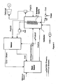
Figure 10 . It is also partly due to the fact that theLEC reactor 17 contains metal oxides which have much higher thermal mass than even brick. - The LEC reactor can be interfaced with an embedded
gasifier 18 to: - (A) either meet the energy demands when CH4 concentration is lower than self-sustaining levels; or
- (B) to make partial use of the excess heat (see
Figure 10 ). - LEC modules can be scaled up to meet any VAM flow rate or methane concentration either through:
- 1. Physical enlargement of the LEC reactor and an increase in the solid inventory or alternatively by
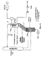
- 2. Parallelisation of a number of LEC modules 19 as shown in
Figure 11 . - Preliminary investigations suggest that the latter approach can handle fluctuations in methane concentration more effectively/robustly and is also more cost effective.
- A LEC reactor is inherently very safe for a number of reasons:
- 1. The temperatures in the oxidiser and reducer sections are not a function of reaction kinetics or gas flow rate, but only of the thermo-physical properties of the gas and solid materials.
- 2. Therefore the reactor can be operated at temperatures lower than flaming combustion simply by adjusting the solid inventory.
- 3. The embedded lamellas act as a flame arrester.
Claims (5)
- A method of removing methane from ventilation air by cycling metal or metal oxide particles in a chemical looping process in one or more reactors where the metal particles are alternately reduced and oxidised, and passing ventilation air through one or more of said reactors to convert the air plus methane into reduced air plus water plus carbon dioxide, wherein there are upper and lower reactors connected by an array of parallel inclined plates forming lamellas, the upper reactor forming an oxidiser section and the lower reactor forming a reducer section, wherein the lamellas provide an internal circulation allowing lighter particles to travel to the upper oxidiser section, while keeping heavier particles in the lower reducer section.
- A method as claimed in claim 1 wherein the lighter particles comprise Fe3O4 and the heavier particles comprise Fe2O3.
- A method as claimed in claim 1 wherein the lighter particles comprise CuO and the heavier particles comprise Cu.
- A method as claimed in any one of claims 1 to 3 wherein a gasifier is embedded in the upper reactor.
- A method as claimed in any one of claims 1 to 4 wherein a plurality of upper and lower reactors each connected by a lamella array are operated in parallel to increase the throughput of the method.
Priority Applications (3)
| Application Number | Priority Date | Filing Date | Title |
|---|---|---|---|
| PL17202923T PL3345864T3 (en) | 2011-09-30 | 2012-09-28 | Chemical looping removal of ventilation air methane |
| PL12836598T PL2760790T3 (en) | 2011-09-30 | 2012-09-28 | Chemical looping removal of ventilation air methane |
| EP17202923.3A EP3345864B1 (en) | 2011-09-30 | 2012-09-28 | Chemical looping removal of ventilation air methane |
Applications Claiming Priority (2)
| Application Number | Priority Date | Filing Date | Title |
|---|---|---|---|
| AU2011904045A AU2011904045A0 (en) | 2011-09-30 | Chemical Looping Removal of Ventilation Air Methane | |
| PCT/AU2012/001173 WO2013044308A1 (en) | 2011-09-30 | 2012-09-28 | Chemical looping removal of ventilation air methane |
Related Child Applications (2)
| Application Number | Title | Priority Date | Filing Date |
|---|---|---|---|
| EP17202923.3A Division EP3345864B1 (en) | 2011-09-30 | 2012-09-28 | Chemical looping removal of ventilation air methane |
| EP17202923.3A Division-Into EP3345864B1 (en) | 2011-09-30 | 2012-09-28 | Chemical looping removal of ventilation air methane |
Publications (3)
| Publication Number | Publication Date |
|---|---|
| EP2760790A1 EP2760790A1 (en) | 2014-08-06 |
| EP2760790A4 EP2760790A4 (en) | 2015-06-24 |
| EP2760790B1 true EP2760790B1 (en) | 2018-01-10 |
Family
ID=47994025
Family Applications (2)
| Application Number | Title | Priority Date | Filing Date |
|---|---|---|---|
| EP17202923.3A Not-in-force EP3345864B1 (en) | 2011-09-30 | 2012-09-28 | Chemical looping removal of ventilation air methane |
| EP12836598.8A Not-in-force EP2760790B1 (en) | 2011-09-30 | 2012-09-28 | Chemical looping removal of ventilation air methane |
Family Applications Before (1)
| Application Number | Title | Priority Date | Filing Date |
|---|---|---|---|
| EP17202923.3A Not-in-force EP3345864B1 (en) | 2011-09-30 | 2012-09-28 | Chemical looping removal of ventilation air methane |
Country Status (7)
| Country | Link |
|---|---|
| US (1) | US9314740B2 (en) |
| EP (2) | EP3345864B1 (en) |
| AU (1) | AU2012315483B2 (en) |
| IN (1) | IN2014KN00899A (en) |
| PL (2) | PL2760790T3 (en) |
| WO (1) | WO2013044308A1 (en) |
| ZA (1) | ZA201402182B (en) |
Families Citing this family (7)
| Publication number | Priority date | Publication date | Assignee | Title |
|---|---|---|---|---|
| CN104870894A (en) * | 2012-11-30 | 2015-08-26 | 沙特阿拉伯石油公司 | Staged chemical looping process with integrated oxygen generation |
| AU2014289972B2 (en) * | 2013-07-11 | 2019-02-14 | The University Of Newcastle | Mineral carbonate looping reactor for ventilation air methane mitigation |
| WO2017097733A1 (en) * | 2015-12-07 | 2017-06-15 | Dürr Systems Ag | A mixing and processing system of ventilation air methane and coal mine methane |
| CN109078600B (en) * | 2018-07-13 | 2020-09-08 | 安徽省含山县锦华氧化锌厂 | Zinc oxide production and processing robot |
| KR102644556B1 (en) * | 2018-12-04 | 2024-03-07 | 현대자동차주식회사 | Method And System For Producing Hydrogen Using Waste Gas |
| EP3699991B1 (en) * | 2019-02-25 | 2021-04-14 | ETH Zurich | Systems and reactors for storage of electrical energy |
| CN112201465B (en) * | 2020-10-10 | 2022-05-06 | 河北建投能源科学技术研究院有限公司 | Preparation method of modified biological magnetic fluid for desulfurization wastewater treatment |
Family Cites Families (9)
| Publication number | Priority date | Publication date | Assignee | Title |
|---|---|---|---|---|
| ITMI20040555A1 (en) * | 2004-03-23 | 2004-06-23 | Eni Spa | PROCEDURE FOR THE PRODUCTION OF HYDROGEN AND THE CO-PRODUCTION OF CARBON DIOXIDE |
| WO2008070931A1 (en) | 2006-12-15 | 2008-06-19 | Eestech, Inc. | A combustion apparatus |
| JP4538077B2 (en) | 2008-06-13 | 2010-09-08 | 川崎重工業株式会社 | Lean fuel intake gas turbine |
| WO2010085835A1 (en) * | 2009-01-29 | 2010-08-05 | Commonwealth Scientific And Industrial Research Organisation | System and method for mitigating at least one component from a fluid stream |
| US20110081277A1 (en) | 2009-10-05 | 2011-04-07 | Balon Jr Thomas Hamilton | Regenerative thermal oxidiser |
| US8753108B2 (en) * | 2012-03-30 | 2014-06-17 | Alstom Technology Ltd | Method and apparatus for treatment of unburnts |
| CN102618349B (en) * | 2012-03-31 | 2014-07-02 | 昆明理工大学 | Oxygen carrier for methane chemical looping combustion and preparation method for oxygen carrier |
| US9481837B2 (en) * | 2013-03-15 | 2016-11-01 | The Babcock & Wilcox Company | Chemical looping processes for partial oxidation of carbonaceous fuels |
| CN103552983A (en) * | 2013-10-25 | 2014-02-05 | 西南石油大学 | CaO guided technology for producing hydrogen through steam reforming and chemical looping combustion of methane |
-
2012
- 2012-09-28 IN IN899KON2014 patent/IN2014KN00899A/en unknown
- 2012-09-28 AU AU2012315483A patent/AU2012315483B2/en active Active
- 2012-09-28 US US14/348,500 patent/US9314740B2/en active Active
- 2012-09-28 WO PCT/AU2012/001173 patent/WO2013044308A1/en not_active Ceased
- 2012-09-28 EP EP17202923.3A patent/EP3345864B1/en not_active Not-in-force
- 2012-09-28 EP EP12836598.8A patent/EP2760790B1/en not_active Not-in-force
- 2012-09-28 PL PL12836598T patent/PL2760790T3/en unknown
- 2012-09-28 PL PL17202923T patent/PL3345864T3/en unknown
-
2014
- 2014-03-25 ZA ZA2014/02182A patent/ZA201402182B/en unknown
Non-Patent Citations (1)
| Title |
|---|
| None * |
Also Published As
| Publication number | Publication date |
|---|---|
| US9314740B2 (en) | 2016-04-19 |
| EP3345864B1 (en) | 2019-06-26 |
| ZA201402182B (en) | 2015-04-29 |
| US20140227157A1 (en) | 2014-08-14 |
| PL3345864T3 (en) | 2020-02-28 |
| WO2013044308A1 (en) | 2013-04-04 |
| AU2012315483A1 (en) | 2014-04-10 |
| IN2014KN00899A (en) | 2015-10-09 |
| EP2760790A1 (en) | 2014-08-06 |
| PL2760790T3 (en) | 2018-04-30 |
| EP3345864A1 (en) | 2018-07-11 |
| AU2012315483B2 (en) | 2016-06-02 |
| EP2760790A4 (en) | 2015-06-24 |
Similar Documents
| Publication | Publication Date | Title |
|---|---|---|
| EP3345864B1 (en) | Chemical looping removal of ventilation air methane | |
| US8506915B2 (en) | Method for recovering CO2 by means of CaO and the exothermic reduction of a solid | |
| Fan et al. | Utilization of chemical looping strategy in coal gasification processes | |
| EP2808073B1 (en) | System for CO2 capture from a combustion flue gas using a CaO/CaCO3 chemical loop | |
| CN107849462B (en) | Syngas production via metal oxide cyclic reduction and oxidation | |
| EP1933087A2 (en) | Systems and methods using an unmixed fuel processor | |
| KR20220085705A (en) | Methods of producing one or more products using a feedstock gas reactor | |
| JP2013166148A (en) | Reduction of co and nox in regenerator flue gas | |
| CN101216175B (en) | Oxygen carrier gasifying combustion method for loading oxygen and device | |
| EP3169879B1 (en) | Integrated calcium looping combined cycle for sour gas applications | |
| US7780749B2 (en) | Unmixed fuel processors and methods for using the same | |
| CN214745627U (en) | A chemical chain combustion power generation system of ammonia | |
| Duan et al. | Fluidized Bed Reactors for Carbon Capture: A Review of Advancing Combustion and Sorption Techniques for Decarbonization | |
| US20120100055A1 (en) | Chemical looping air separation unit and methods of use | |
| US8555652B1 (en) | Air-independent internal oxidation | |
| AU2014289972B2 (en) | Mineral carbonate looping reactor for ventilation air methane mitigation | |
| EP3617590A1 (en) | Incineration apparatus and method | |
| Hassan et al. | Parametric and exergetic analysis of a power plant with CO2 and capture using chemical looping combustion | |
| Pröll et al. | Chemical looping combustion and reforming | |
| TWI554331B (en) | Hydrocarbon fuel reactor with carbon dioxide separated and purified | |
| Gallucci et al. | A review on recent patents on chemical and calcium looping processes | |
| Amin et al. | Chemical looping combustion for gaseous fuels: principles, oxygen carriers, and reactor design | |
| Seepana et al. | Thermodynamic Analysis of Chemical Looping Combustion Based Power Plants for Gaseous and Solid Fuels | |
| TWI572562B (en) | Reactor of Hydrocarbon Fuel Having Space Efficiency for Separating and Purifying Carbon Dioxide | |
| EP2867583A2 (en) | Process for obtaining thermal energy by the combustion of hydrogen in admixture with carbon oxides, nitrogen oxides and/or sulphur oxides and installation for the application of the process |
Legal Events
| Date | Code | Title | Description |
|---|---|---|---|
| PUAI | Public reference made under article 153(3) epc to a published international application that has entered the european phase |
Free format text: ORIGINAL CODE: 0009012 |
|
| 17P | Request for examination filed |
Effective date: 20140324 |
|
| AK | Designated contracting states |
Kind code of ref document: A1 Designated state(s): AL AT BE BG CH CY CZ DE DK EE ES FI FR GB GR HR HU IE IS IT LI LT LU LV MC MK MT NL NO PL PT RO RS SE SI SK SM TR |
|
| DAX | Request for extension of the european patent (deleted) | ||
| RA4 | Supplementary search report drawn up and despatched (corrected) |
Effective date: 20150526 |
|
| RIC1 | Information provided on ipc code assigned before grant |
Ipc: B01D 53/72 20060101ALI20150519BHEP Ipc: C01B 3/10 20060101ALI20150519BHEP Ipc: B01D 53/86 20060101ALI20150519BHEP Ipc: C01B 31/20 20060101AFI20150519BHEP |
|
| 17Q | First examination report despatched |
Effective date: 20160518 |
|
| REG | Reference to a national code |
Ref country code: DE Ref legal event code: R079 Ref document number: 602012041892 Country of ref document: DE Free format text: PREVIOUS MAIN CLASS: C01B0031200000 Ipc: C01B0003100000 |
|
| RIC1 | Information provided on ipc code assigned before grant |
Ipc: B01D 53/86 20060101ALI20170713BHEP Ipc: B01D 53/72 20060101ALI20170713BHEP Ipc: C01B 3/10 20060101AFI20170713BHEP |
|
| GRAP | Despatch of communication of intention to grant a patent |
Free format text: ORIGINAL CODE: EPIDOSNIGR1 |
|
| INTG | Intention to grant announced |
Effective date: 20170825 |
|
| GRAS | Grant fee paid |
Free format text: ORIGINAL CODE: EPIDOSNIGR3 |
|
| GRAA | (expected) grant |
Free format text: ORIGINAL CODE: 0009210 |
|
| AK | Designated contracting states |
Kind code of ref document: B1 Designated state(s): AL AT BE BG CH CY CZ DE DK EE ES FI FR GB GR HR HU IE IS IT LI LT LU LV MC MK MT NL NO PL PT RO RS SE SI SK SM TR |
|
| REG | Reference to a national code |
Ref country code: CH Ref legal event code: EP Ref country code: AT Ref legal event code: REF Ref document number: 962172 Country of ref document: AT Kind code of ref document: T Effective date: 20180115 |
|
| REG | Reference to a national code |
Ref country code: IE Ref legal event code: FG4D |
|
| RAP2 | Party data changed (patent owner data changed or rights of a patent transferred) |
Owner name: THE UNIVERSITY OF NEWCASTLE |
|
| REG | Reference to a national code |
Ref country code: DE Ref legal event code: R096 Ref document number: 602012041892 Country of ref document: DE |
|
| REG | Reference to a national code |
Ref country code: NL Ref legal event code: MP Effective date: 20180110 |
|
| REG | Reference to a national code |
Ref country code: AT Ref legal event code: MK05 Ref document number: 962172 Country of ref document: AT Kind code of ref document: T Effective date: 20180110 |
|
| PG25 | Lapsed in a contracting state [announced via postgrant information from national office to epo] |
Ref country code: NL Free format text: LAPSE BECAUSE OF FAILURE TO SUBMIT A TRANSLATION OF THE DESCRIPTION OR TO PAY THE FEE WITHIN THE PRESCRIBED TIME-LIMIT Effective date: 20180110 |
|
| PG25 | Lapsed in a contracting state [announced via postgrant information from national office to epo] |
Ref country code: ES Free format text: LAPSE BECAUSE OF FAILURE TO SUBMIT A TRANSLATION OF THE DESCRIPTION OR TO PAY THE FEE WITHIN THE PRESCRIBED TIME-LIMIT Effective date: 20180110 Ref country code: LT Free format text: LAPSE BECAUSE OF FAILURE TO SUBMIT A TRANSLATION OF THE DESCRIPTION OR TO PAY THE FEE WITHIN THE PRESCRIBED TIME-LIMIT Effective date: 20180110 Ref country code: CY Free format text: LAPSE BECAUSE OF FAILURE TO SUBMIT A TRANSLATION OF THE DESCRIPTION OR TO PAY THE FEE WITHIN THE PRESCRIBED TIME-LIMIT Effective date: 20180110 Ref country code: NO Free format text: LAPSE BECAUSE OF FAILURE TO SUBMIT A TRANSLATION OF THE DESCRIPTION OR TO PAY THE FEE WITHIN THE PRESCRIBED TIME-LIMIT Effective date: 20180410 Ref country code: HR Free format text: LAPSE BECAUSE OF FAILURE TO SUBMIT A TRANSLATION OF THE DESCRIPTION OR TO PAY THE FEE WITHIN THE PRESCRIBED TIME-LIMIT Effective date: 20180110 Ref country code: FI Free format text: LAPSE BECAUSE OF FAILURE TO SUBMIT A TRANSLATION OF THE DESCRIPTION OR TO PAY THE FEE WITHIN THE PRESCRIBED TIME-LIMIT Effective date: 20180110 |
|
| PG25 | Lapsed in a contracting state [announced via postgrant information from national office to epo] |
Ref country code: IS Free format text: LAPSE BECAUSE OF FAILURE TO SUBMIT A TRANSLATION OF THE DESCRIPTION OR TO PAY THE FEE WITHIN THE PRESCRIBED TIME-LIMIT Effective date: 20180510 Ref country code: RS Free format text: LAPSE BECAUSE OF FAILURE TO SUBMIT A TRANSLATION OF THE DESCRIPTION OR TO PAY THE FEE WITHIN THE PRESCRIBED TIME-LIMIT Effective date: 20180110 Ref country code: SE Free format text: LAPSE BECAUSE OF FAILURE TO SUBMIT A TRANSLATION OF THE DESCRIPTION OR TO PAY THE FEE WITHIN THE PRESCRIBED TIME-LIMIT Effective date: 20180110 Ref country code: LV Free format text: LAPSE BECAUSE OF FAILURE TO SUBMIT A TRANSLATION OF THE DESCRIPTION OR TO PAY THE FEE WITHIN THE PRESCRIBED TIME-LIMIT Effective date: 20180110 Ref country code: AT Free format text: LAPSE BECAUSE OF FAILURE TO SUBMIT A TRANSLATION OF THE DESCRIPTION OR TO PAY THE FEE WITHIN THE PRESCRIBED TIME-LIMIT Effective date: 20180110 Ref country code: GR Free format text: LAPSE BECAUSE OF FAILURE TO SUBMIT A TRANSLATION OF THE DESCRIPTION OR TO PAY THE FEE WITHIN THE PRESCRIBED TIME-LIMIT Effective date: 20180411 Ref country code: BG Free format text: LAPSE BECAUSE OF FAILURE TO SUBMIT A TRANSLATION OF THE DESCRIPTION OR TO PAY THE FEE WITHIN THE PRESCRIBED TIME-LIMIT Effective date: 20180410 |
|
| REG | Reference to a national code |
Ref country code: FR Ref legal event code: PLFP Year of fee payment: 7 |
|
| REG | Reference to a national code |
Ref country code: DE Ref legal event code: R097 Ref document number: 602012041892 Country of ref document: DE |
|
| PG25 | Lapsed in a contracting state [announced via postgrant information from national office to epo] |
Ref country code: RO Free format text: LAPSE BECAUSE OF FAILURE TO SUBMIT A TRANSLATION OF THE DESCRIPTION OR TO PAY THE FEE WITHIN THE PRESCRIBED TIME-LIMIT Effective date: 20180110 Ref country code: AL Free format text: LAPSE BECAUSE OF FAILURE TO SUBMIT A TRANSLATION OF THE DESCRIPTION OR TO PAY THE FEE WITHIN THE PRESCRIBED TIME-LIMIT Effective date: 20180110 Ref country code: IT Free format text: LAPSE BECAUSE OF FAILURE TO SUBMIT A TRANSLATION OF THE DESCRIPTION OR TO PAY THE FEE WITHIN THE PRESCRIBED TIME-LIMIT Effective date: 20180110 Ref country code: EE Free format text: LAPSE BECAUSE OF FAILURE TO SUBMIT A TRANSLATION OF THE DESCRIPTION OR TO PAY THE FEE WITHIN THE PRESCRIBED TIME-LIMIT Effective date: 20180110 |
|
| PLBE | No opposition filed within time limit |
Free format text: ORIGINAL CODE: 0009261 |
|
| STAA | Information on the status of an ep patent application or granted ep patent |
Free format text: STATUS: NO OPPOSITION FILED WITHIN TIME LIMIT |
|
| PG25 | Lapsed in a contracting state [announced via postgrant information from national office to epo] |
Ref country code: DK Free format text: LAPSE BECAUSE OF FAILURE TO SUBMIT A TRANSLATION OF THE DESCRIPTION OR TO PAY THE FEE WITHIN THE PRESCRIBED TIME-LIMIT Effective date: 20180110 Ref country code: SM Free format text: LAPSE BECAUSE OF FAILURE TO SUBMIT A TRANSLATION OF THE DESCRIPTION OR TO PAY THE FEE WITHIN THE PRESCRIBED TIME-LIMIT Effective date: 20180110 Ref country code: SK Free format text: LAPSE BECAUSE OF FAILURE TO SUBMIT A TRANSLATION OF THE DESCRIPTION OR TO PAY THE FEE WITHIN THE PRESCRIBED TIME-LIMIT Effective date: 20180110 Ref country code: CZ Free format text: LAPSE BECAUSE OF FAILURE TO SUBMIT A TRANSLATION OF THE DESCRIPTION OR TO PAY THE FEE WITHIN THE PRESCRIBED TIME-LIMIT Effective date: 20180110 |
|
| 26N | No opposition filed |
Effective date: 20181011 |
|
| PG25 | Lapsed in a contracting state [announced via postgrant information from national office to epo] |
Ref country code: SI Free format text: LAPSE BECAUSE OF FAILURE TO SUBMIT A TRANSLATION OF THE DESCRIPTION OR TO PAY THE FEE WITHIN THE PRESCRIBED TIME-LIMIT Effective date: 20180110 |
|
| PG25 | Lapsed in a contracting state [announced via postgrant information from national office to epo] |
Ref country code: MC Free format text: LAPSE BECAUSE OF FAILURE TO SUBMIT A TRANSLATION OF THE DESCRIPTION OR TO PAY THE FEE WITHIN THE PRESCRIBED TIME-LIMIT Effective date: 20180110 |
|
| REG | Reference to a national code |
Ref country code: CH Ref legal event code: PL |
|
| REG | Reference to a national code |
Ref country code: BE Ref legal event code: MM Effective date: 20180930 |
|
| REG | Reference to a national code |
Ref country code: IE Ref legal event code: MM4A |
|
| PG25 | Lapsed in a contracting state [announced via postgrant information from national office to epo] |
Ref country code: LU Free format text: LAPSE BECAUSE OF NON-PAYMENT OF DUE FEES Effective date: 20180928 |
|
| PG25 | Lapsed in a contracting state [announced via postgrant information from national office to epo] |
Ref country code: IE Free format text: LAPSE BECAUSE OF NON-PAYMENT OF DUE FEES Effective date: 20180928 |
|
| PG25 | Lapsed in a contracting state [announced via postgrant information from national office to epo] |
Ref country code: BE Free format text: LAPSE BECAUSE OF NON-PAYMENT OF DUE FEES Effective date: 20180930 Ref country code: LI Free format text: LAPSE BECAUSE OF NON-PAYMENT OF DUE FEES Effective date: 20180930 Ref country code: CH Free format text: LAPSE BECAUSE OF NON-PAYMENT OF DUE FEES Effective date: 20180930 |
|
| PGFP | Annual fee paid to national office [announced via postgrant information from national office to epo] |
Ref country code: FR Payment date: 20190927 Year of fee payment: 8 Ref country code: DE Payment date: 20190917 Year of fee payment: 8 |
|
| PGFP | Annual fee paid to national office [announced via postgrant information from national office to epo] |
Ref country code: PL Payment date: 20190916 Year of fee payment: 8 |
|
| PGFP | Annual fee paid to national office [announced via postgrant information from national office to epo] |
Ref country code: GB Payment date: 20190926 Year of fee payment: 8 |
|
| PG25 | Lapsed in a contracting state [announced via postgrant information from national office to epo] |
Ref country code: MT Free format text: LAPSE BECAUSE OF NON-PAYMENT OF DUE FEES Effective date: 20180928 |
|
| PG25 | Lapsed in a contracting state [announced via postgrant information from national office to epo] |
Ref country code: TR Free format text: LAPSE BECAUSE OF FAILURE TO SUBMIT A TRANSLATION OF THE DESCRIPTION OR TO PAY THE FEE WITHIN THE PRESCRIBED TIME-LIMIT Effective date: 20180110 |
|
| PG25 | Lapsed in a contracting state [announced via postgrant information from national office to epo] |
Ref country code: PT Free format text: LAPSE BECAUSE OF FAILURE TO SUBMIT A TRANSLATION OF THE DESCRIPTION OR TO PAY THE FEE WITHIN THE PRESCRIBED TIME-LIMIT Effective date: 20180110 Ref country code: HU Free format text: LAPSE BECAUSE OF FAILURE TO SUBMIT A TRANSLATION OF THE DESCRIPTION OR TO PAY THE FEE WITHIN THE PRESCRIBED TIME-LIMIT; INVALID AB INITIO Effective date: 20120928 |
|
| PG25 | Lapsed in a contracting state [announced via postgrant information from national office to epo] |
Ref country code: MK Free format text: LAPSE BECAUSE OF NON-PAYMENT OF DUE FEES Effective date: 20180110 |
|
| REG | Reference to a national code |
Ref country code: DE Ref legal event code: R119 Ref document number: 602012041892 Country of ref document: DE |
|
| GBPC | Gb: european patent ceased through non-payment of renewal fee |
Effective date: 20200928 |
|
| PG25 | Lapsed in a contracting state [announced via postgrant information from national office to epo] |
Ref country code: DE Free format text: LAPSE BECAUSE OF NON-PAYMENT OF DUE FEES Effective date: 20210401 Ref country code: FR Free format text: LAPSE BECAUSE OF NON-PAYMENT OF DUE FEES Effective date: 20200930 |
|
| PG25 | Lapsed in a contracting state [announced via postgrant information from national office to epo] |
Ref country code: GB Free format text: LAPSE BECAUSE OF NON-PAYMENT OF DUE FEES Effective date: 20200928 |
|
| PG25 | Lapsed in a contracting state [announced via postgrant information from national office to epo] |
Ref country code: PL Free format text: LAPSE BECAUSE OF NON-PAYMENT OF DUE FEES Effective date: 20200928 |
|
| P01 | Opt-out of the competence of the unified patent court (upc) registered |
Effective date: 20230515 |