EP2760165A2 - Systems and methods to detect bus network fault and topology - Google Patents
Systems and methods to detect bus network fault and topology Download PDFInfo
- Publication number
- EP2760165A2 EP2760165A2 EP14165404.6A EP14165404A EP2760165A2 EP 2760165 A2 EP2760165 A2 EP 2760165A2 EP 14165404 A EP14165404 A EP 14165404A EP 2760165 A2 EP2760165 A2 EP 2760165A2
- Authority
- EP
- European Patent Office
- Prior art keywords
- bus
- luminaire
- devices
- control device
- bus interface
- Prior art date
- Legal status (The legal status is an assumption and is not a legal conclusion. Google has not performed a legal analysis and makes no representation as to the accuracy of the status listed.)
- Granted
Links
- 238000000034 method Methods 0.000 title description 37
- 238000002955 isolation Methods 0.000 claims description 72
- 238000004891 communication Methods 0.000 claims description 68
- 230000004044 response Effects 0.000 claims description 25
- 230000009471 action Effects 0.000 claims description 18
- 230000000007 visual effect Effects 0.000 claims description 14
- 230000003213 activating effect Effects 0.000 claims description 2
- 238000005286 illumination Methods 0.000 claims description 2
- 239000004020 conductor Substances 0.000 description 13
- 230000008569 process Effects 0.000 description 10
- 239000003990 capacitor Substances 0.000 description 9
- 238000001514 detection method Methods 0.000 description 9
- 238000009434 installation Methods 0.000 description 8
- 230000008901 benefit Effects 0.000 description 6
- 230000008878 coupling Effects 0.000 description 4
- 238000010168 coupling process Methods 0.000 description 4
- 238000005859 coupling reaction Methods 0.000 description 4
- 230000001351 cycling effect Effects 0.000 description 4
- 238000012544 monitoring process Methods 0.000 description 4
- 230000005540 biological transmission Effects 0.000 description 3
- 230000006870 function Effects 0.000 description 3
- 230000003287 optical effect Effects 0.000 description 3
- 230000002093 peripheral effect Effects 0.000 description 2
- 230000001902 propagating effect Effects 0.000 description 2
- 230000002411 adverse Effects 0.000 description 1
- 230000010267 cellular communication Effects 0.000 description 1
- 230000001413 cellular effect Effects 0.000 description 1
- 230000000295 complement effect Effects 0.000 description 1
- 238000004590 computer program Methods 0.000 description 1
- 238000013500 data storage Methods 0.000 description 1
- 238000010586 diagram Methods 0.000 description 1
- 230000000694 effects Effects 0.000 description 1
- 238000004146 energy storage Methods 0.000 description 1
- 238000011835 investigation Methods 0.000 description 1
- 238000013507 mapping Methods 0.000 description 1
- 239000004065 semiconductor Substances 0.000 description 1
- 239000000126 substance Substances 0.000 description 1
- 230000009466 transformation Effects 0.000 description 1
- 238000000844 transformation Methods 0.000 description 1
- 238000013024 troubleshooting Methods 0.000 description 1
- 238000010200 validation analysis Methods 0.000 description 1
Images


Classifications
-
- H—ELECTRICITY
- H04—ELECTRIC COMMUNICATION TECHNIQUE
- H04L—TRANSMISSION OF DIGITAL INFORMATION, e.g. TELEGRAPHIC COMMUNICATION
- H04L41/00—Arrangements for maintenance, administration or management of data switching networks, e.g. of packet switching networks
- H04L41/06—Management of faults, events, alarms or notifications
- H04L41/0677—Localisation of faults
-
- H—ELECTRICITY
- H04—ELECTRIC COMMUNICATION TECHNIQUE
- H04L—TRANSMISSION OF DIGITAL INFORMATION, e.g. TELEGRAPHIC COMMUNICATION
- H04L12/00—Data switching networks
- H04L12/28—Data switching networks characterised by path configuration, e.g. LAN [Local Area Networks] or WAN [Wide Area Networks]
- H04L12/40—Bus networks
- H04L12/40006—Architecture of a communication node
- H04L12/40032—Details regarding a bus interface enhancer
-
- H—ELECTRICITY
- H04—ELECTRIC COMMUNICATION TECHNIQUE
- H04L—TRANSMISSION OF DIGITAL INFORMATION, e.g. TELEGRAPHIC COMMUNICATION
- H04L41/00—Arrangements for maintenance, administration or management of data switching networks, e.g. of packet switching networks
- H04L41/12—Discovery or management of network topologies
-
- H—ELECTRICITY
- H05—ELECTRIC TECHNIQUES NOT OTHERWISE PROVIDED FOR
- H05B—ELECTRIC HEATING; ELECTRIC LIGHT SOURCES NOT OTHERWISE PROVIDED FOR; CIRCUIT ARRANGEMENTS FOR ELECTRIC LIGHT SOURCES, IN GENERAL
- H05B47/00—Circuit arrangements for operating light sources in general, i.e. where the type of light source is not relevant
- H05B47/10—Controlling the light source
- H05B47/175—Controlling the light source by remote control
- H05B47/18—Controlling the light source by remote control via data-bus transmission
Definitions
- Bus networks are used in a variety of fields and applications to interconnect devices and allow communication, power transmission, and other functionality.
- One such bus network is known as a Digital Addressable Lighting Interface (DALI), which is a bus architecture standard used in controlling devices in a building (such as sensors, lighting devices, and shades).
- DALI provides a two-wire bus that allows power to be supplied to, and communication between, devices on the bus.
- the presence of voltage indicates a first state (i.e., a logical "1"), while the shorting of the two wires by any device on the bus indicates a second state (i.e., a logical "0").
- a first state i.e., a logical "1”
- the shorting of the two wires by any device on the bus indicates a second state (i.e., a logical "0").
- devices can use the two-wire DALI bus to communicate with each other.
- Faults in a communication system can be numerous, and include wiring faults, short circuits between the conductors of the bus, open circuits, wire loops, breaks, and interference (e.g., from nearby motors or other devices).
- bus networks such as a DALI lighting control bus, RS485 networks and others, nodes may branch off from a trunk. If the trunk is shorted, communication can be impossible and locating the fault tedious and time consuming.
- determining the manner in which the nodes of a bus network are interconnected is useful for a variety of purposes, but can be both difficult and time consuming using conventional systems and methods.
- topology determining the manner in which the nodes of a bus network are interconnected
- a system includes a bus interface for connecting to a bus and a switch coupled to the bus interface, the switch configured to alternate between an open state and a closed state.
- the system is connected to the bus via the bus interface when the switch is in the closed state, and the system is disconnected from the bus via the bus interface when the switch is in the open state.
- a method comprises coupling plurality of devices to a bus, wherein at least one of the plurality of devices includes: a bus interface, a transceiver coupled to the bus interface, the transceiver for transmitting and receiving data via the bus interface, and a switch coupled to the bus interface, the switch configured to alternate between an open state and a closed state, wherein the device is connected to the bus via the bus interface when the switch is in the closed state, wherein the device is disconnected from the bus via the bus interface when the switch is in the open state, and wherein communication with one or more other of the plurality of devices subsequent to the device on the bus is interrupted when the switch is in its open state.
- the method further includes configuring the switch of a device of the plurality of devices from the open state to the closed state, receiving a communication from one or more of the plurality of devices, and determining a wiring topology based on the communication from the one or more of the plurality of devices.
- a method comprises monitoring a bus to identify a sequence in which each of a plurality of devices are coupled to a bus, and determining a wiring topology based on the sequence.
- a method comprises measuring one or more of a current and a voltage on a bus in response to a communication by a device coupled to the bus, determining a wiring impedance between a power supply coupled to the bus and the device, and determining a distance between the power supply and the device based on the determined wiring impedance.
- references to "one embodiment”, “an embodiment”, “an example embodiment”, etc. indicate that the embodiment described may include a particular feature, structure, or characteristic, but every embodiment may not necessarily include the particular feature, structure, or characteristic. Moreover, such phrases are not necessarily referring to the same embodiment. Further, when a particular feature, structure, or characteristic is described in connection with an embodiment, it is submitted that it is within the knowledge of one skilled in the art to effect such feature, structure, or characteristic in connection with other embodiments whether or not explicitly described. After reading the description, it will be apparent to one skilled in the relevant art(s) how to implement the disclosure in alternative embodiments.
- the methods described herein are implemented using the various particular machines described herein.
- the methods described herein may be implemented using the below particular machines, and those hereinafter developed, in any suitable combination, as would be appreciated immediately by one skilled in the art. Further, as is unambiguous from this disclosure, the methods described herein may result in various transformations of certain articles.
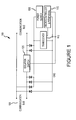
- Figure 1 illustrates an exemplary embodiment of a network device 100 that can be used with a DALI network or other bus architectures.
- the device 100 may also be referred to herein as a "node.”
- the device 100 includes a bus interface 105 and a transceiver 110 for transmitting and receiving data via the bus interface 105.
- the device 100 further includes a microprocessor and peripherals 115 for controlling the device 100 (peripherals may include, among other things, circuitry to create a dimming signal to an external ballast), and a power supply 120 for powering the device 100.
- the device 100 also includes a fault isolation switch 125 for connecting and disconnecting the device 100 from the bus via the bus interface 105.
- Embodiments of this disclosure may operate in conjunction with any number and type of different devices on a bus.
- the device 100 may be any type of DALI-compatible device, such as a lighting device, sensor, keypad, and/or shade.
- the device 100 may be configured to perform any other suitable function.
- the device 100 may be configured to act as a control device in order to facilitate communication between other devices on the bus.
- the device 100 may function as a bus arbiter to declare the bus free for any other device(s) on the bus to commence communication (rather than instructing a specific node to respond).
- Devices according to other embodiments of this disclosure may also be configured to operate with bus architectures such as RS485, Controller Area Network (CAN), and/or Local Interconnect Network (LIN).
- bus architectures such as RS485, Controller Area Network (CAN), and/or Local Interconnect Network (LIN).
- the device 100 may include any suitable bus interface 105.
- the bus interface 105 is configured to couple the device 100 to a two-conductor DALI communication bus or other two-conductor bus.
- the fault isolation switch 125 is coupled to the bus interface 105 and is configured to alternate between an open state and a closed state.
- the fault isolation switch 125 is in the closed state, the device 100 is connected to the bus via the bus interface 105, and when the fault isolation switch 125 is in the open state, the device 100 is disconnected from the bus via the bus interface 105.
- the communication bus to which the bus interface 105 connects, uses two conductors. Accordingly, two faults that may occur on this bus include an open circuit and a short circuit between the two conductors.
- the device 100 may be configured to couple to, for example, a CAT5 cable in which case additional open/short permutations could occur by virtue of the CAT5 cable having multiple conductors.
- the fault isolation switch 125 allows the device 100 to be disconnected from the bus by interrupting one of the two signal wires of the communication bus.
- the fault isolation switch 125 allows installers to isolate open circuits and short circuits.
- open circuits communication to nodes behind, or subsequent to, the open circuit is not possible, thus the location of the open circuit can be identified by identifying the last communicating node on the bus.
- a short normally affects all nodes on the bus such that communication with all nodes is preempted.
- the fault isolation switch 125 allows most of the nodes on the bus to remain functional while helping to isolate the source of the short.
- the fault isolation switch 125 may be implemented in any manner, such as by utilizing mechanical relays or semiconductors (such as MOSFETs).
- a MOSFET may be implemented at low cost and low power consumption for two-conductor buses (such as a DALI bus).
- a mechanical relay may be advantageous since such relays are available with multiple contacts that can be connected to the conductors of the bus in order to disconnect the device from the bus.
- the fault isolation switch 125 is configured to remain open by default until configured into its closed position. During the power up phase, the node 100 will then close its fault isolation switch 125 and monitor for conditions of a fault. In the case of a DALI communication, the bus would appear shorted (no voltage) upon closing the fault isolation switch 125.
- a node 100 may also include circuitry to monitor the bus and determine other adverse conditions such as increases in noise. If a node 100 detects such conditions, it will open its fault isolation switch 125 again and thereby isolate the fault (which would otherwise prevent any communication). The node 100 would then (actively or upon request) communicate this condition to facilitate troubleshooting.
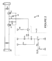
- a fault isolation switch 200 includes connectors J2A and J2B that connect to a two-conductor bus via the bus interface 105 (shown in Figure 1 ).
- One conductor of the bus passes through from a terminal 5 to a terminal 2, while the other conductor passes from a terminal 4, via MOSFETs Q17 and Q18, to a terminal 1.
- the MOSFETs Q17 and Q18 may be controlled to either pass the signal or isolate the signal.
- the MOSFETs Q17 and Q18 are configured back-to-back such that the internal body diodes cannot form a conductive path.
- a capacitor C8 stores a voltage across a gate-source of each of the MOSFETs Q17 and Q18, while a resistor R17 discharges the capacitor C8 in order to open the fault isolation switch 200.
- a zener diode 205 protects the gates of the MOSFETs Q17 and Q18 from excessive voltage.
- a gate voltage higher than the gate-source threshold voltage of the MOSFETs Q17 and Q18 is applied to turn them on.
- the voltage at the respective gates of the MOSFETs Q17 and Q18 must be higher than the sum of the gate-source-threshold and the positive signal amplitude. This higher voltage can be derived by a charge pump 210.
- a microcontroller (not shown in Figure 2 ) toggles an input 2W_SW, in turn turning a transistor Q10 on and off.
- a capacitor C9 charges via a diode D7A to a source voltage VCC. While the transistor Q10 is off, a negative terminal of the capacitor C9 is raised to the source voltage VCC via a resistor R14. The capacitor C9 then discharges into a capacitor C8 via a diode D7B and a transistor Q1. Once the capacitor C8 is sufficiently charged, the MOSFETs Q17 and Q18 turn on. To turn off the fault isolation switch 200, the microcontroller ceases to toggle the input 2W_SW and the capacitor C8 discharges via the resistor R17. The transistor Q1 and a resistor R20 prevent turning on the fault isolation switch 200 in the configuration when the negative signal path is interrupted. Without it, the capacitor C8 would charge uncontrolled via the diodes D7A and D7B.
- the device 100 may be configured to alternate its fault isolation switch 125 between the open state and closed state in any suitable manner.
- the fault isolation switch 125 can be controlled via the microcontroller 115 of the device 100.
- the device 100 may be configured to alternate the states of the fault isolation switch 125 in response to a signal from another device via the bus.
- the device 100 may be configured to leave the fault isolation switch 125 in its open or closed state indefinitely (e.g., until receipt of a second signal indicating the fault isolation switch 125 should be alternated to the other state) or for a predetermined period of time and then alternate to the other state.
- the fault isolation switch 125 may also be configured to remain in one state (e.g., the open state) for a predetermined period of time, after which it remains in the other state (e.g., the closed state) indefinitely.
- the device 100 may be configured to detect any form of fault, such as wiring faults, short circuits between the conductors of the cable, open circuits, wire loops, breaks, and interference. Open and short circuits may be detected using the device 100 as described previously. Additionally, circuitry for detection of faults can be integrated into the device 100. Upon power up, the device 100 closes its fault isolation switch 125 and observes the bus. If the bus appears faulty, the device 100 is configured to open its fault isolation switch 125, thereby isolating the fault. In an embodiment, where the device 100 acts as a control device on the bus, the device 100 may be configured to instruct other nodes on the bus to temporarily close their respective fault isolation switches.
- any form of fault such as wiring faults, short circuits between the conductors of the cable, open circuits, wire loops, breaks, and interference. Open and short circuits may be detected using the device 100 as described previously. Additionally, circuitry for detection of faults can be integrated into the device 100.
- the device 100 closes its fault isolation switch 125 and
- the device 100 acting as a control device can assess the bus conditions to identify faults. After a predetermined period of time, or when instructed to by the device 100 acting as a control device, each node on the bus configures its fault isolation switch from the closed position to the open position. In some cases, such as where conditions are suitable for communication over the bus, the device 100 acting as a control device may instruct a node to permanently close its fault isolation switch in order to bring a fault condition to an installer's attention.
- a bus network As discussed above, knowledge of the topology of a bus network is often very important. For example, in order to dim lights (e.g., connected to a DALI network in a building) in response to daylight, it can be important to know which of the lighting nodes are located near windows of the building and which lighting nodes are located interior to the building.
- a software tool is used to show the unique address of each node that has been discovered on the bus. Installers then instruct the node to cycle its lights on and off and attempt to locate which lights are cycling on and off. In some instances, such as an open warehouse, this process is relatively efficient. In other cases, such as in an office building, it is often difficult to determine which lights are cycling without extensive manual investigation, making the process very time consuming and, consequently, very expensive.
- embodiments of this disclosure can help determine the topology of the bus network to expedite the process of physically locating nodes, particularly in cases (such as many lighting installations) where an installer connects nodes in an ordered fashion (e.g., the installer follows hallways and wires all the nodes within one office before moving to another).
- an installer connects nodes in an ordered fashion (e.g., the installer follows hallways and wires all the nodes within one office before moving to another).
- the physical locations of nodes are determined, they can be entered into a floor plan through a user interface on a computer (whether portable, such as but not limited to a tablet, laptop, etc., or not portable, such as but not limited to a desktop computer) in a process called "mapping."
- nodes equipped with a fault isolation switch can be used to determine the wiring topology, as well as to isolate faults as described above.
- the fault isolation switches 125 of all devices 100 on a bus are opened.
- a signal is sent by the master control unit to the first node 100 to configure its fault isolation switch 125 to the closed position, allowing the identification of the next subsequent node 100 on the bus.
- two or more nodes 100 appear as a fault isolation switch 125 is closed, indicating that the communication bus has been branched, in which case each branch can be investigated separately.
- This procedure can also detect loops, where a communication bus branches off just to rejoin the initial branch at some location further down the bus.
- all nodes on a bus include a fault isolation switch 125 or are otherwise capable of being selectively connected and disconnected from the bus in order to determine faults or topology.
- the switch may be included in a subset of nodes to reduce system cost.
- a specific fault may not be able to be traced to a single node 100, rather to a group of nodes 100. In practice, however, this uncertainty may not pose a problem where the nodes 100 in a group of nodes 100 are within a reasonable vicinity of each other.
- each node 100 can be instructed to open its switch only temporarily.
- the fault isolation switch 125 for each node 100 can be configured to remain open for a predetermined period of time such that the internal power supplies (or energy storage devices) of the nodes 100 can power the nodes 100.
- this allows the lighting to remain fully functional during the topology detection process.
- the location of the new node 100 relative to other nodes 100 can be determined without interrupting operation of the lighting control system. During the period of temporary disconnection, a command may be broadcast.
- the command may instruct those nodes 100 that can still communicate to set a flag.
- the commands are relatively short such that the duration of the disconnection is likewise short. Then, when the fault isolation switch 125 is closed again, the system may determine which nodes 100 have their flag set and which do not. Those nodes 100 that don't have their flag set are located behind the node 100 that temporarily disconnected the fault isolation switch 125.
- nodes 100 may be configured to detect a temporary loss of power and set a flag upon such an event. One node 100 is then instructed to temporarily open the fault isolation switch 125, where upon nodes 100 behind the one node 100 set their flag. Then, when the fault isolation switch 125 is closed again, the system determines which nodes 100 saw the temporary disconnection and which did not.
- communications from nodes 100 on the bus can be monitored to determine the wiring topology of the bus.
- a command can be issued onto the bus such that any nodes 100 that receive the command will respond with a communication (e.g., via transceiver 110).
- a communication e.g., via transceiver 110.
- Figures 3A-3C illustrate an example of determining wiring topology according to embodiments.
- Figure 3A depicts the actual wiring topology of nodes [1] through [7], each of which is a node 100 as described herein.
- the fault isolation switch 125 for each node [1] through [7] is opened, and the nodes [1] through [7] with which communication is interrupted is determined.
- the fault isolation switch 125 for the node [1] is opened, resulting in communication with the nodes [3], [5], [6], and [7] being interrupted.
- the fault isolation switch 125 for the node [1] is then closed, and the fault isolation switch 125 for the node [2] is opened, and so forth through each of the nodes [1] through [7], yielding the table in Figure 3B .
- the remaining nodes that is the nodes [3] and [7] in the above example, indicate the direct children of a node, that is the node [5].
- the nodes [3] and [7] are indeed the direct children of the node [5].
- Figure 3C depicts the results of this process for each of the nodes [1] through [7], which can be used to depict the topology of the bus (e.g., using a tree structure as shown in Figure 3A ).
- determining a bus topology for a computer system bus it may be more desirable to identify the parent nodes rather than an arbitrary number of children, that is, identifying that a node Q is the parent of those nodes remaining in the group of children.
- the node [5] is parent to the nodes [3] and [7].
- the topology of a bus can be determined based on monitoring the sequence in which devices are connected to the bus. As described earlier, embodiments can be used to determine bus topology while the system is operational. In such cases, the bus can be monitored and the addition of nodes detected and their sequence of addition noted. In this embodiment, the sequence in which nodes are connected to the system can be used to determine the wiring topology, particularly where the nodes are added in a daisy chain configuration. This method may also complement other topology scanning methods. For example, where (as described above) only a certain percentage of nodes include a fault isolation switch, the sequence in which nodes are added can help determine the topology in between the nodes with switches.
- the electrical characteristics of a bus of any suitable bus architecture may be used to help determine the wiring topology of the bus.
- the topology of a DALI bus can be determined using the measured wiring impedance of the bus between a power supply coupled to the bus and a device coupled to the bus.
- FIG. 4 depicts a typical transceiver section 400 for a DALI node.
- a bridge rectifier D1 rectifies the DALI signal and makes the transceiver polarity insensitive.
- voltage is present at the DALI lines and is high enough so a Zener diode D2 conducts. Consequently, an LED D3 on the receive optocoupler illuminates and, a transistor T1 conducts.
- a microcontroller recognizes this via an RX pin.
- the resistor R1 limits current through the LED D3.
- the voltage on the DALI line is too low for the Zener diode D2 to conduct, and therefore the LED D3 and the transistor T1 will be off.
- a node must short the DALI lines in order to generate a logical zero on the bus.
- the bus is simply left un-shorted.
- the microcontroller for the device passes current through a diode D4, in turn causing a transistor T2 to conduct.
- a current is provided through a resistor R3 into a base of a transistor T3, which then shorts the DALI bus through the bridge rectifier D1.
- a reading of current and voltage can be recorded while the DALI device shorts the bus.
- the voltage reading can be adjusted by an offset based on a characteristic such as the manufacturer, model, device type, and/ or any other characteristic that may influence the measured voltage when the device communicates.
- the device's manufacturer and model information is retrieved via the communication bus and a looked up in a database to obtain the offset for the device.
- the wire impedance between the power supply and the device can be calculated according to Ohm's law. The wire impedance is proportional to the length of wire, allowing the distance to each node to be determined. This can thus help determine the wiring topology of a bus, even in cases where the nodes are not equipped with the above-described fault isolation switch.
- the node creates a (largely current independent) voltage drop of two diode drops in the bridge rectifier D1 and another base-emitter drop in the transistor T3, or approximately 2.1 Volt (V[Offset]).
- V[Offset] a voltage drop of two diode drops in the bridge rectifier D1 and another base-emitter drop in the transistor T3, or approximately 2.1 Volt (V[Offset]).
- the power supply may lower the voltage to a level of V[zero] in order to limit the current to 250mA.
- a communications system can experience a variety of different fault conditions, many of which can be difficult to localize.
- Conventional diagnostic equipment is often expensive, delicate, and/or difficult to operate.
- determining the exact location of the fault can still be tedious and time consuming.
- a bus device (such as device 100 shown in Figure 1 , with or without a fault isolation switch 125) is configured to power up in an "installation mode" to help identify faults as an installer wires the device to a live (powered) bus.
- a system (such as a computer system coupled to the bus) monitors the bus and keeps an inventory of each node 100 and its type.
- the computer system can further transmit a communication to the node 100, which is received by the node 100 (e.g., by transceiver 110).
- the communication is validated by the node 100 and, if the validation is successful (indicating the node 100 is functional and installed properly), the node 100 may activate one or more of its features.
- Features of a node 100 can be activated in any suitable manner, such as being alternately activated and deactivated repeatedly, activated for a predetermined period of time and then deactivated, and/ or activated/ deactivated in combination with other features of the node 100.
- keypads may feature LED indicators that generate a visual indicator (such as flashing the indicators a number of times).
- Nodes 100 connected to lighting devices may generate a visual indicator that includes cycling the lights on and off a number of times.
- the node 100 may also generated an audible indicator, such as a sound played through a speaker coupled to the node 100 or an audible "clicking" of a mechanical relay of the node 100 as it cycles lights.
- a node 100 may generate any combination of visual and/ or audible indicators.
- the audible and/or visual indicators generated by the node 100 provide immediate feedback to the installer that the installation of the node 100 is (or remains) functional. If a node 100 fails to generate the indicators, the installer knows that a fault must be present between the last successfully detected node 100 and the recently installed node 100. This embodiment may also be particularly effective in detecting intermittent faults, such as may be caused by a loose or improperly seated connector.
- a plurality of devices coupled to a bus include a keypad and a lighting device.
- the lighting device In response to a communication from the keypad over the bus (e.g., due to a button being pushed on a keypad), the lighting device is configured to alternate between two or more states. For example, the lighting device may cycle between the states of high brightness, low brightness, and off. Among other things, this cycling helps demonstrate to the installer that nodes are both capable of communication and correctly wired to the lighting device's ballast or LED driver.
- any number of keypads and lighting devices can be tested. All lights can be cycled simultaneously, individually, or in groups.
- the computer system may include any number of computing devices connected in any manner, such as through a distributed network.
- the computer system may communicate and/or interface with any number of users and/or other computing devices to send and receive any suitable information in any manner, such as via a local area network (LAN), cellular communication, radio, satellite transmission, a modem, the Internet, and/ or the like.
- LAN local area network
- non-transitory is to be understood to remove only propagating transitory signals per se from the claim scope and does not relinquish rights to all standard computer-readable media that are not only propagating transitory signals per se. Stated another way, the meaning of the term “non-transitory computer-readable medium” should be construed to exclude only those types of transitory computer-readable media which were found in In Re Nuijten to fall outside the scope of patentable subject matter under 35 U.S.C. ⁇ 101.
- the disclosure includes a method, it is contemplated that it may be embodied as computer program instructions on a tangible computer-readable carrier, such as a magnetic or optical memory or a magnetic or optical disk.
- a tangible computer-readable carrier such as a magnetic or optical memory or a magnetic or optical disk.
- the fault isolation switch may further comprise a fault detection circuit, wherein the fault detection circuit is configured to identify a fault associated with the bus, and to alternate the fault detection switch to the open state in response to identifying the fault.
- the fault detection switch has an initial operation mode and a steady operation mode, and the fault detection switch is configured to default to the open state while in the initial operation mode.
- the fault isolation switch may be configured to alternate between the open state and the closed state in response to a signal received from the bus via the bus interface.
- the fault isolation switch may be configured to remain in the open state or the closed state until receipt of a second signal from the bus via the bus interface.
- the device further comprises a microcontroller, wherein the microcontroller is configured to control the device and to provide output signals to a further device to which the device is connected.
- a method comprises:
- the method may further comprise:
- the method may further comprise:
- the method may further comprise:
- configuring may comprise:
- the method may further comprise:
- a system comprising:
- transmitting may comprise:
- the device may further comprise:
- transmitting may comprise:
Landscapes
- Engineering & Computer Science (AREA)
- Computer Networks & Wireless Communication (AREA)
- Signal Processing (AREA)
- Small-Scale Networks (AREA)
- Circuit Arrangement For Electric Light Sources In General (AREA)
Abstract
Description
- This Application is claims priority to United States Patent Application Serial No.
13/161,321, filed June 15, 2011 13/161,349, filed June 15, 2011 - Bus networks are used in a variety of fields and applications to interconnect devices and allow communication, power transmission, and other functionality. One such bus network is known as a Digital Addressable Lighting Interface (DALI), which is a bus architecture standard used in controlling devices in a building (such as sensors, lighting devices, and shades). DALI provides a two-wire bus that allows power to be supplied to, and communication between, devices on the bus. In the DALI architecture, the presence of voltage indicates a first state (i.e., a logical "1"), while the shorting of the two wires by any device on the bus indicates a second state (i.e., a logical "0"). In this manner, devices can use the two-wire DALI bus to communicate with each other.
- Faults in a communication system can be numerous, and include wiring faults, short circuits between the conductors of the bus, open circuits, wire loops, breaks, and interference (e.g., from nearby motors or other devices). In some bus networks, such as a DALI lighting control bus, RS485 networks and others, nodes may branch off from a trunk. If the trunk is shorted, communication can be impossible and locating the fault tedious and time consuming.
- Likewise, determining the manner in which the nodes of a bus network are interconnected (known as the "topology" of the network) is useful for a variety of purposes, but can be both difficult and time consuming using conventional systems and methods. In installations that include large numbers of nodes, such as a lighting control network, or installation with long wires, problems due to faults and determining bus topology can be exacerbated.
- Embodiments in this disclosure address these and other issues. Among other things, embodiments in this disclosure help identify faults on a bus, as well as to determine the topology of a bus network. A system according to one embodiment includes a bus interface for connecting to a bus and a switch coupled to the bus interface, the switch configured to alternate between an open state and a closed state. The system is connected to the bus via the bus interface when the switch is in the closed state, and the system is disconnected from the bus via the bus interface when the switch is in the open state.
- A method according to an embodiment comprises coupling plurality of devices to a bus, wherein at least one of the plurality of devices includes: a bus interface, a transceiver coupled to the bus interface, the transceiver for transmitting and receiving data via the bus interface, and a switch coupled to the bus interface, the switch configured to alternate between an open state and a closed state, wherein the device is connected to the bus via the bus interface when the switch is in the closed state, wherein the device is disconnected from the bus via the bus interface when the switch is in the open state, and wherein communication with one or more other of the plurality of devices subsequent to the device on the bus is interrupted when the switch is in its open state. The method further includes configuring the switch of a device of the plurality of devices from the open state to the closed state, receiving a communication from one or more of the plurality of devices, and determining a wiring topology based on the communication from the one or more of the plurality of devices.
- A method according to an embodiment comprises monitoring a bus to identify a sequence in which each of a plurality of devices are coupled to a bus, and determining a wiring topology based on the sequence.
- A method according to an embodiment comprises measuring one or more of a current and a voltage on a bus in response to a communication by a device coupled to the bus, determining a wiring impedance between a power supply coupled to the bus and the device, and determining a distance between the power supply and the device based on the determined wiring impedance.
- It is to be understood that both the foregoing general description and the following detailed description are exemplary and explanatory only and are not restrictive of the disclosure, as claimed.
- A more complete understanding of the embodiments of the present disclosure may be derived by referring to the detailed description and claims when considered in connection with the following illustrative figures.
-
Figure 1 illustrates an exemplary bus device in accordance with various embodiments. -
Figure 2 depicts an exemplary switch circuit for use in bus devices in accordance with various embodiments. -
Figures 3A-3C illustrate a method for determining bus topology in accordance with various embodiments. -
Figure 4 depicts a typical prior art transceiver section for a DALI node. - While exemplary embodiments in this disclosure are described in conjunction with the DALI bus architecture, this disclosure may be used in conjunction with any other suitable bus architecture.
- The detailed description of exemplary embodiments herein makes reference to the accompanying drawings and pictures, which show the exemplary embodiment by way of illustration and its best mode. While these exemplary embodiments are described in sufficient detail to enable those skilled in the art to practice the disclosure, it should be understood that other embodiments may be realized and that logical and mechanical changes may be made without departing from the spirit and scope of the disclosure. Thus, the detailed description herein is presented for purposes of illustration only and not of limitation. For example, the steps recited in any of the method or process descriptions may be executed in any order and are not limited to the order presented. Moreover, any of the functions or steps may be outsourced to or performed by one or more third parties. Furthermore, any reference to singular includes plural embodiments, and any reference to more than one component may include a singular embodiment.
- In the detailed description herein, references to "one embodiment", "an embodiment", "an example embodiment", etc., indicate that the embodiment described may include a particular feature, structure, or characteristic, but every embodiment may not necessarily include the particular feature, structure, or characteristic. Moreover, such phrases are not necessarily referring to the same embodiment. Further, when a particular feature, structure, or characteristic is described in connection with an embodiment, it is submitted that it is within the knowledge of one skilled in the art to effect such feature, structure, or characteristic in connection with other embodiments whether or not explicitly described. After reading the description, it will be apparent to one skilled in the relevant art(s) how to implement the disclosure in alternative embodiments.
- In various embodiments, the methods described herein are implemented using the various particular machines described herein. The methods described herein may be implemented using the below particular machines, and those hereinafter developed, in any suitable combination, as would be appreciated immediately by one skilled in the art. Further, as is unambiguous from this disclosure, the methods described herein may result in various transformations of certain articles.
-
Figure 1 illustrates an exemplary embodiment of anetwork device 100 that can be used with a DALI network or other bus architectures. Thedevice 100 may also be referred to herein as a "node." Thedevice 100 includes abus interface 105 and atransceiver 110 for transmitting and receiving data via thebus interface 105. Thedevice 100 further includes a microprocessor andperipherals 115 for controlling the device 100 (peripherals may include, among other things, circuitry to create a dimming signal to an external ballast), and apower supply 120 for powering thedevice 100. Thedevice 100 also includes afault isolation switch 125 for connecting and disconnecting thedevice 100 from the bus via thebus interface 105. - Embodiments of this disclosure may operate in conjunction with any number and type of different devices on a bus. In the exemplary embodiment depicted in
Figure 1 , thedevice 100 may be any type of DALI-compatible device, such as a lighting device, sensor, keypad, and/or shade. Thedevice 100 may be configured to perform any other suitable function. For example, thedevice 100 may be configured to act as a control device in order to facilitate communication between other devices on the bus. In one embodiment, thedevice 100 may function as a bus arbiter to declare the bus free for any other device(s) on the bus to commence communication (rather than instructing a specific node to respond). Devices according to other embodiments of this disclosure may also be configured to operate with bus architectures such as RS485, Controller Area Network (CAN), and/or Local Interconnect Network (LIN). - The
device 100 may include anysuitable bus interface 105. In the exemplary embodiment depicted inFigure 1 , thebus interface 105 is configured to couple thedevice 100 to a two-conductor DALI communication bus or other two-conductor bus. - The
fault isolation switch 125 is coupled to thebus interface 105 and is configured to alternate between an open state and a closed state. When thefault isolation switch 125 is in the closed state, thedevice 100 is connected to the bus via thebus interface 105, and when thefault isolation switch 125 is in the open state, thedevice 100 is disconnected from the bus via thebus interface 105. In the exemplary embodiment depicted inFigure 1 , the communication bus, to which thebus interface 105 connects, uses two conductors. Accordingly, two faults that may occur on this bus include an open circuit and a short circuit between the two conductors. In certain embodiments, thedevice 100 may be configured to couple to, for example, a CAT5 cable in which case additional open/short permutations could occur by virtue of the CAT5 cable having multiple conductors. - In the embodiment depicted in
Figure 1 , thefault isolation switch 125 allows thedevice 100 to be disconnected from the bus by interrupting one of the two signal wires of the communication bus. Among other things, thefault isolation switch 125 allows installers to isolate open circuits and short circuits. In the case of open circuits, communication to nodes behind, or subsequent to, the open circuit is not possible, thus the location of the open circuit can be identified by identifying the last communicating node on the bus. In the case of a short circuit, a short normally affects all nodes on the bus such that communication with all nodes is preempted. Thefault isolation switch 125, however, allows most of the nodes on the bus to remain functional while helping to isolate the source of the short. - The fault isolation switch 125may be implemented in any manner, such as by utilizing mechanical relays or semiconductors (such as MOSFETs). For example, a MOSFET may be implemented at low cost and low power consumption for two-conductor buses (such as a DALI bus). In other cases, such as when the bus coupled to the device includes more than two conductors, a mechanical relay may be advantageous since such relays are available with multiple contacts that can be connected to the conductors of the bus in order to disconnect the device from the bus.
- In some bus architectures, if the
fault isolation switch 125 is initially closed when thedevice 100 is installed, and a short circuit was present on the bus, then no power could be delivered to thenode 100. Consequently, thenode 100 may not be able to power up or open thefault isolation switch 125, preventing the fault from being isolated. Accordingly, in one embodiment, thefault isolation switch 125 is configured to remain open by default until configured into its closed position. During the power up phase, thenode 100 will then close itsfault isolation switch 125 and monitor for conditions of a fault. In the case of a DALI communication, the bus would appear shorted (no voltage) upon closing thefault isolation switch 125. As described in more detail below, anode 100 may also include circuitry to monitor the bus and determine other adverse conditions such as increases in noise. If anode 100 detects such conditions, it will open itsfault isolation switch 125 again and thereby isolate the fault (which would otherwise prevent any communication). Thenode 100 would then (actively or upon request) communicate this condition to facilitate troubleshooting. - An exemplary embodiment of the fault isolation switch is depicted in
Figure 2 . In this embodiment, afault isolation switch 200 includes connectors J2A and J2B that connect to a two-conductor bus via the bus interface 105 (shown inFigure 1 ). One conductor of the bus passes through from aterminal 5 to aterminal 2, while the other conductor passes from aterminal 4, via MOSFETs Q17 and Q18, to aterminal 1. The MOSFETs Q17 and Q18 may be controlled to either pass the signal or isolate the signal. The MOSFETs Q17 and Q18 are configured back-to-back such that the internal body diodes cannot form a conductive path. A capacitor C8 stores a voltage across a gate-source of each of the MOSFETs Q17 and Q18, while a resistor R17 discharges the capacitor C8 in order to open thefault isolation switch 200. Azener diode 205 protects the gates of the MOSFETs Q17 and Q18 from excessive voltage. - In operation, if the MOSFETs Q17 and Q18 interrupt the negative signal path, a gate voltage higher than the gate-source threshold voltage of the MOSFETs Q17 and Q18 is applied to turn them on. If the MOSFETs Q17 and Q18 interrupt the positive signal path, the voltage at the respective gates of the MOSFETs Q17 and Q18 must be higher than the sum of the gate-source-threshold and the positive signal amplitude. This higher voltage can be derived by a
charge pump 210. In order to activate thecharge pump 210, a microcontroller (not shown inFigure 2 ) toggles an input 2W_SW, in turn turning a transistor Q10 on and off. While the transistor Q10 is on, a capacitor C9 charges via a diode D7A to a source voltage VCC. While the transistor Q10 is off, a negative terminal of the capacitor C9 is raised to the source voltage VCC via a resistor R14. The capacitor C9 then discharges into a capacitor C8 via a diode D7B and a transistor Q1. Once the capacitor C8 is sufficiently charged, the MOSFETs Q17 and Q18 turn on. To turn off thefault isolation switch 200, the microcontroller ceases to toggle the input 2W_SW and the capacitor C8 discharges via the resistor R17. The transistor Q1 and a resistor R20 prevent turning on thefault isolation switch 200 in the configuration when the negative signal path is interrupted. Without it, the capacitor C8 would charge uncontrolled via the diodes D7A and D7B. - The
device 100 may be configured to alternate itsfault isolation switch 125 between the open state and closed state in any suitable manner. For example, thefault isolation switch 125 can be controlled via themicrocontroller 115 of thedevice 100. Additionally (or alternately), thedevice 100 may be configured to alternate the states of thefault isolation switch 125 in response to a signal from another device via the bus. Thedevice 100 may be configured to leave thefault isolation switch 125 in its open or closed state indefinitely (e.g., until receipt of a second signal indicating thefault isolation switch 125 should be alternated to the other state) or for a predetermined period of time and then alternate to the other state. The fault isolation switch 125may also be configured to remain in one state (e.g., the open state) for a predetermined period of time, after which it remains in the other state (e.g., the closed state) indefinitely. - The
device 100 may be configured to detect any form of fault, such as wiring faults, short circuits between the conductors of the cable, open circuits, wire loops, breaks, and interference. Open and short circuits may be detected using thedevice 100 as described previously. Additionally, circuitry for detection of faults can be integrated into thedevice 100. Upon power up, thedevice 100 closes itsfault isolation switch 125 and observes the bus. If the bus appears faulty, thedevice 100 is configured to open itsfault isolation switch 125, thereby isolating the fault. In an embodiment, where thedevice 100 acts as a control device on the bus, thedevice 100 may be configured to instruct other nodes on the bus to temporarily close their respective fault isolation switches. During this time, thedevice 100 acting as a control device can assess the bus conditions to identify faults. After a predetermined period of time, or when instructed to by thedevice 100 acting as a control device, each node on the bus configures its fault isolation switch from the closed position to the open position. In some cases, such as where conditions are suitable for communication over the bus, thedevice 100 acting as a control device may instruct a node to permanently close its fault isolation switch in order to bring a fault condition to an installer's attention. - As discussed above, knowledge of the topology of a bus network is often very important. For example, in order to dim lights (e.g., connected to a DALI network in a building) in response to daylight, it can be important to know which of the lighting nodes are located near windows of the building and which lighting nodes are located interior to the building. In a conventional DALI installation, a software tool is used to show the unique address of each node that has been discovered on the bus. Installers then instruct the node to cycle its lights on and off and attempt to locate which lights are cycling on and off. In some instances, such as an open warehouse, this process is relatively efficient. In other cases, such as in an office building, it is often difficult to determine which lights are cycling without extensive manual investigation, making the process very time consuming and, consequently, very expensive.
- Among other things, embodiments of this disclosure can help determine the topology of the bus network to expedite the process of physically locating nodes, particularly in cases (such as many lighting installations) where an installer connects nodes in an ordered fashion (e.g., the installer follows hallways and wires all the nodes within one office before moving to another). As the physical locations of nodes are determined, they can be entered into a floor plan through a user interface on a computer (whether portable, such as but not limited to a tablet, laptop, etc., or not portable, such as but not limited to a desktop computer) in a process called "mapping."
- In one embodiment, nodes equipped with a fault isolation switch (such as the
node 100 shown inFigure 1 ) can be used to determine the wiring topology, as well as to isolate faults as described above. In this embodiment, the fault isolation switches 125 of alldevices 100 on a bus are opened. As a result, only afirst node 100 directly connected to a master control unit can be seen on the bus, because all subsequent nodes are disconnected. A signal is sent by the master control unit to thefirst node 100 to configure itsfault isolation switch 125 to the closed position, allowing the identification of the nextsubsequent node 100 on the bus. It is possible that two ormore nodes 100 appear as afault isolation switch 125 is closed, indicating that the communication bus has been branched, in which case each branch can be investigated separately. This procedure can also detect loops, where a communication bus branches off just to rejoin the initial branch at some location further down the bus. - In some embodiments, it is not necessary that all nodes on a bus include a
fault isolation switch 125 or are otherwise capable of being selectively connected and disconnected from the bus in order to determine faults or topology. For example, the switch may be included in a subset of nodes to reduce system cost. In such cases, a specific fault may not be able to be traced to asingle node 100, rather to a group ofnodes 100. In practice, however, this uncertainty may not pose a problem where thenodes 100 in a group ofnodes 100 are within a reasonable vicinity of each other. - In order to prevent
nodes 100 far down the communication bus from being disconnected (and thus non-functional) for long periods of time during the topology detection process, eachnode 100 can be instructed to open its switch only temporarily. In one embodiment, thefault isolation switch 125 for eachnode 100 can be configured to remain open for a predetermined period of time such that the internal power supplies (or energy storage devices) of thenodes 100 can power thenodes 100. In a DALI lighting control system, for example, this allows the lighting to remain fully functional during the topology detection process. Moreover, asnodes 100 are added to the system, the location of thenew node 100 relative toother nodes 100 can be determined without interrupting operation of the lighting control system. During the period of temporary disconnection, a command may be broadcast. For example, the command may instruct thosenodes 100 that can still communicate to set a flag. In one embodiment, the commands are relatively short such that the duration of the disconnection is likewise short. Then, when thefault isolation switch 125 is closed again, the system may determine whichnodes 100 have their flag set and which do not. Thosenodes 100 that don't have their flag set are located behind thenode 100 that temporarily disconnected thefault isolation switch 125. - In an embodiment,
nodes 100 may be configured to detect a temporary loss of power and set a flag upon such an event. Onenode 100 is then instructed to temporarily open thefault isolation switch 125, where uponnodes 100 behind the onenode 100 set their flag. Then, when thefault isolation switch 125 is closed again, the system determines whichnodes 100 saw the temporary disconnection and which did not. - In an embodiment, communications from
nodes 100 on the bus can be monitored to determine the wiring topology of the bus. For example, a command can be issued onto the bus such that anynodes 100 that receive the command will respond with a communication (e.g., via transceiver 110). With knowledge ofnodes 100 having their fault isolation switches 125 in the open or closed states, and by identifying thenodes 100 on the bus from which such a communication is received, (i.e., whichnodes 100 saw the command and which did not) the bus topology can be determined. -
Figures 3A-3C illustrate an example of determining wiring topology according to embodiments.Figure 3A depicts the actual wiring topology of nodes [1] through [7], each of which is anode 100 as described herein. Thefault isolation switch 125 for each node [1] through [7] is opened, and the nodes [1] through [7] with which communication is interrupted is determined. For example, referring now toFigure 3B , thefault isolation switch 125 for the node [1] is opened, resulting in communication with the nodes [3], [5], [6], and [7] being interrupted. Thefault isolation switch 125 for the node [1] is then closed, and thefault isolation switch 125 for the node [2] is opened, and so forth through each of the nodes [1] through [7], yielding the table inFigure 3B . - Based on the results in
Figure 3B , a group of child nodes (Y) for each node (X) is identified. For each of the child nodes (Y) in the group of child nodes (Y), those nodes (Y) from the group of child nodes (Y) that are also children of a child node (Y) are removed. For example, for the node X=[5], the group of children is the nodes [3], [6], and [7]. Removing the nodes from the group that appear as children of Y yields: - Y=[3] removes [6]
- Y=[6] removes none
- Y=[7] removes none.
- The remaining children in the group are thus the nodes [3] and [7].
- The remaining nodes, that is the nodes [3] and [7] in the above example, indicate the direct children of a node, that is the node [5]. As can be verified in the actual topology diagram in
Figure 3A , the nodes [3] and [7] are indeed the direct children of the node [5].Figure 3C depicts the results of this process for each of the nodes [1] through [7], which can be used to depict the topology of the bus (e.g., using a tree structure as shown inFigure 3A ). - In certain embodiments, such as determining a bus topology for a computer system bus, it may be more desirable to identify the parent nodes rather than an arbitrary number of children, that is, identifying that a node Q is the parent of those nodes remaining in the group of children. In the above example with regards to
Figures 3A-3C , the node [5] is parent to the nodes [3] and [7]. - Additionally, or alternately, the topology of a bus can be determined based on monitoring the sequence in which devices are connected to the bus. As described earlier, embodiments can be used to determine bus topology while the system is operational. In such cases, the bus can be monitored and the addition of nodes detected and their sequence of addition noted. In this embodiment, the sequence in which nodes are connected to the system can be used to determine the wiring topology, particularly where the nodes are added in a daisy chain configuration. This method may also complement other topology scanning methods. For example, where (as described above) only a certain percentage of nodes include a fault isolation switch, the sequence in which nodes are added can help determine the topology in between the nodes with switches.
- Additionally, the electrical characteristics of a bus of any suitable bus architecture may be used to help determine the wiring topology of the bus. In one embodiment, the topology of a DALI bus can be determined using the measured wiring impedance of the bus between a power supply coupled to the bus and a device coupled to the bus.
-
Figure 4 depicts atypical transceiver section 400 for a DALI node. In this example, a bridge rectifier D1 rectifies the DALI signal and makes the transceiver polarity insensitive. During a logical one, voltage is present at the DALI lines and is high enough so a Zener diode D2 conducts. Consequently, an LED D3 on the receive optocoupler illuminates and, a transistor T1 conducts. A microcontroller recognizes this via an RX pin. The resistor R1 limits current through the LED D3. During a logical zero, the voltage on the DALI line is too low for the Zener diode D2 to conduct, and therefore the LED D3 and the transistor T1 will be off. - As described previously, a node must short the DALI lines in order to generate a logical zero on the bus. During a logical one, the bus is simply left un-shorted. In order to create a logical zero, the microcontroller for the device (not shown) passes current through a diode D4, in turn causing a transistor T2 to conduct. In turn, a current is provided through a resistor R3 into a base of a transistor T3, which then shorts the DALI bus through the bridge rectifier D1.
- At the power supply (not shown), a reading of current and voltage can be recorded while the DALI device shorts the bus. The voltage reading can be adjusted by an offset based on a characteristic such as the manufacturer, model, device type, and/ or any other characteristic that may influence the measured voltage when the device communicates. In one embodiment, the device's manufacturer and model information is retrieved via the communication bus and a looked up in a database to obtain the offset for the device. Once the voltage has been adjusted, the wire impedance between the power supply and the device can be calculated according to Ohm's law. The wire impedance is proportional to the length of wire, allowing the distance to each node to be determined. This can thus help determine the wiring topology of a bus, even in cases where the nodes are not equipped with the above-described fault isolation switch.
- In an example, referring again to
Figure 4 , the node creates a (largely current independent) voltage drop of two diode drops in the bridge rectifier D1 and another base-emitter drop in the transistor T3, or approximately 2.1 Volt (V[Offset]). During a logical zero, the power supply may lower the voltage to a level of V[zero] in order to limit the current to 250mA. The wiring impedance, which is proportional to thewire length 1, is then derived via the following equation:
- As discussed previously, a communications system can experience a variety of different fault conditions, many of which can be difficult to localize. Conventional diagnostic equipment is often expensive, delicate, and/or difficult to operate. Moreover, even when conventional systems detect a fault, determining the exact location of the fault can still be tedious and time consuming.
- In one embodiment of the disclosure, a bus device (such as
device 100 shown inFigure 1 , with or without a fault isolation switch 125) is configured to power up in an "installation mode" to help identify faults as an installer wires the device to a live (powered) bus. Asdevices 100 are added to the bus asnodes 100, a system (such as a computer system coupled to the bus) monitors the bus and keeps an inventory of eachnode 100 and its type. - The computer system can further transmit a communication to the
node 100, which is received by the node 100 (e.g., by transceiver 110). The communication is validated by thenode 100 and, if the validation is successful (indicating thenode 100 is functional and installed properly), thenode 100 may activate one or more of its features. Features of anode 100 can be activated in any suitable manner, such as being alternately activated and deactivated repeatedly, activated for a predetermined period of time and then deactivated, and/ or activated/ deactivated in combination with other features of thenode 100. For example, keypads may feature LED indicators that generate a visual indicator (such as flashing the indicators a number of times).Nodes 100 connected to lighting devices may generate a visual indicator that includes cycling the lights on and off a number of times. Thenode 100 may also generated an audible indicator, such as a sound played through a speaker coupled to thenode 100 or an audible "clicking" of a mechanical relay of thenode 100 as it cycles lights. Anode 100 may generate any combination of visual and/ or audible indicators. - In this manner, the audible and/or visual indicators generated by the
node 100 provide immediate feedback to the installer that the installation of thenode 100 is (or remains) functional. If anode 100 fails to generate the indicators, the installer knows that a fault must be present between the last successfully detectednode 100 and the recently installednode 100. This embodiment may also be particularly effective in detecting intermittent faults, such as may be caused by a loose or improperly seated connector. - In an embodiment directed to a lighting system, a plurality of devices coupled to a bus include a keypad and a lighting device. In response to a communication from the keypad over the bus (e.g., due to a button being pushed on a keypad), the lighting device is configured to alternate between two or more states. For example, the lighting device may cycle between the states of high brightness, low brightness, and off. Among other things, this cycling helps demonstrate to the installer that nodes are both capable of communication and correctly wired to the lighting device's ballast or LED driver. In this embodiment, any number of keypads and lighting devices can be tested. All lights can be cycled simultaneously, individually, or in groups.
- The above-described embodiments may be implemented in any manner, such as through hardware, software, or a combination of the two. Functionality implemented through software may be performed by any suitable computer-based system. Such a software program may be stored on any computer-readable medium, such as floppy disks, hard disks, CD-ROMs, DVDs, any type of optical or magneti-optical disks, volatile or non-volatile memory, and/or any other type of media suitable for storing electronic instructions and capable of interfacing with a computing device. Methods according to embodiments of present invention may operate in conjunction with any type of computer system, such as a personal computer (PC), server, cellular phone, personal digital assistant (PDA), portable computer (such as a laptop), embedded computing system, and/ or any other type of computing device. The computer system may include any number of computing devices connected in any manner, such as through a distributed network. The computer system may communicate and/or interface with any number of users and/or other computing devices to send and receive any suitable information in any manner, such as via a local area network (LAN), cellular communication, radio, satellite transmission, a modem, the Internet, and/ or the like.
- The particular implementations shown and described above are illustrative of the invention and its best mode and are not intended to otherwise limit the scope of the present invention in any way. Indeed, for the sake of brevity, conventional data storage, data transmission, and other functional aspects of the systems may not be described in detail. Furthermore, the connecting lines shown in the various figures are intended to represent exemplary functional relationships and/or physical couplings between the various elements. Many alternative or additional functional relationships or physical connections may be present in a practical system.
- The term "non-transitory" is to be understood to remove only propagating transitory signals per se from the claim scope and does not relinquish rights to all standard computer-readable media that are not only propagating transitory signals per se. Stated another way, the meaning of the term "non-transitory computer-readable medium" should be construed to exclude only those types of transitory computer-readable media which were found in In Re Nuijten to fall outside the scope of patentable subject matter under 35 U.S.C. § 101.
- Benefits, other advantages, and solutions to problems have been described herein with regard to specific embodiments. However, the benefits, advantages, solutions to problems, and any elements that may cause any benefit, advantage, or solution to occur or become more pronounced are not to be construed as critical, required, or essential features or elements of the disclosure. The scope of the disclosure is accordingly to be limited by nothing other than the appended claims, in which reference to an element in the singular is not intended to mean "one and only one" unless explicitly so stated, but rather "one or more." Moreover, where a phrase similar to 'at least one of A, B, and C' or 'at least one of A, B, or C' is used in the claims or specification, it is intended that the phrase be interpreted to mean that A alone may be present in an embodiment, B alone may be present in an embodiment, C alone may be present in an embodiment, or that any combination of the elements A, B and C may be present in a single embodiment; for example, A and B, A and C, B and C, or A and B and C. Although the disclosure includes a method, it is contemplated that it may be embodied as computer program instructions on a tangible computer-readable carrier, such as a magnetic or optical memory or a magnetic or optical disk. All structural, chemical, and functional equivalents to the elements of the above-described exemplary embodiments that are known to those of ordinary skill in the art are expressly incorporated herein by reference and are intended to be encompassed by the present claims. Moreover, it is not necessary for a device or method to address each and every problem sought to be solved by the present disclosure, for it to be encompassed by the present claims. Furthermore, no element, component, or method step in the present disclosure is intended to be dedicated to the public regardless of whether the element, component, or method step is explicitly recited in the claims. No claim element herein is to be construed under the provisions of 35 U.S.C. 112, sixth paragraph, unless the element is expressly recited using the phrase "means for." As used herein, the terms "comprises", "comprising", or any other variation thereof, are intended to cover a non-exclusive inclusion, such that a process, method, article, or apparatus that comprises a list of elements does not include only those elements but may include other elements not expressly listed or inherent to such process, method, article, or apparatus.
- Further preferred embodiments are given in the following paragraphs:
- According to various embodiments, a device comprises:
- a bus interface to connect the device to a bus;
- a transceiver to transmit and receive data via the bus over the bus interface; and
- a fault isolation switch connected to the bus interface, wherein the fault isolation switch has an open state and a closed state, such that when the fault isolation switch is in the open state,
- the bus interface is disconnected from the bus and the transceiver is unable to transmit or
- receive data via the bus, and when the fault isolation switch is in the closed state, the bus interface is connected to the bus and the transceiver is able to transmit and receive data via the bus.
- According to various embodiments, the fault isolation switch may further comprise a fault detection circuit, wherein the fault detection circuit is configured to identify a fault associated with the bus, and to alternate the fault detection switch to the open state in response to identifying the fault.
- According to various embodiments, the fault detection switch has an initial operation mode and a steady operation mode, and the fault detection switch is configured to default to the open state while in the initial operation mode.
- According to various embodiments, the fault isolation switch may configured to alternate between the open state and the closed state in response to a signal received from the bus via the bus interface.
- According to various embodiments, the fault isolation switch may configured to remain in the open state or the closed state until receipt of a second signal from the bus via the bus interface.
- According to various embodiments, the device further comprises a microcontroller, wherein the microcontroller is configured to control the device and to provide output signals to a further device to which the device is connected.
- According to various embodiments, a method comprises:
- coupling a plurality of devices to a bus, wherein at least one device of the plurality of devices comprises:
- a bus interface to connect the at least one device to a bus; a transceiver to transmit and receive data via the bus over the bus interface; and
- a fault isolation switch connected to the bus interface, wherein the fault isolation switch has an open state and a closed state, such that when the fault isolation switch is in the open state, the bus interface is disconnected from the bus and the transceiver is unable to transmit or receive data via the bus, and when the fault isolation switch is in the closed state, the bus interface is connected to the bus and the transceiver is able to transmit and receive data via the bus, and wherein communication with one or more other of the plurality of devices subsequent to the device on the bus is interrupted when the switch is in the open state; configuring the fault isolation switch of at least one device of the plurality of devices from the open state to the closed state;
- receiving a communication via the bus from one or more devices in the plurality of devices; and
- repeating the steps of configuring and receiving to determine a wiring topology based on the configured fault isolation switches and the received communications from the plurality of devices.
- According to various embodiments, the method may further comprise:
- configuring the fault isolation switch of a device in the plurality of devices to remain in the open state for a predetermined period of time, and then to alternate to the closed state. According to various embodiments, receiving comprises:
- receiving a communication from one or more devices in the plurality of devices; and
- monitoring the bus to determine the one or more devices in the plurality of devices that transmitted the communication;
- and wherein repeating comprises:
- repeating the steps of configuring, receiving, and monitoring to identify a sequence in which each device in the plurality of devices is coupled to the bus; and determining a wiring topology of the plurality of devices based on the identified sequence.
- According to various embodiments, the method may further comprise:
- coupling a power supply to the bus;
- measuring at least one of a current on the bus and a voltage on a bus in response to receiving a communication via the bus by a device in the plurality of devices coupled to the bus;
- determining a wiring impedance between the power supply and the device; and
- determining a distance between the power supply and the device based on the determined wiring impedance.
- According to various embodiments, the method may further comprise:
- adjusting the at least one measured voltage and measure current by an offset, the offset based on one or more characteristics of the device.
- According to various embodiments, configuring may comprise:
- transmitting a communication via the bus to the plurality of devices coupled to the bus; and wherein receiving comprises:
- receiving one or more response communications via the bus from a first subset of devices in the plurality of devices; and
- based on the received one or more response communications, identifying a second subset of devices in the plurality of devices from which a response
- communication was not received via the bus;
- and wherein repeating comprises:
- using the received one or more response communications and the identified second subset of devices in the plurality of devices to locate a fault on the bus.
- According to various embodiments, the method may further comprise:
- transmitting a communication via the bus to the plurality of devices coupled to the bus;
- receiving one or more response communications via the bus from a first subset of devices in the plurality of devices;
- based on the received one or more response communications and the determined wiring topology, identifying a second subset of devices in the plurality of devices from which a response communication was not received via the bus; and using the received one or more response communications, the determined wiring topology, and the identified second subset of devices in the plurality of devices to locate a fault on the bus.
- According to various embodiments, a system, comprising:
- a system bus;
- a power supply connected to the system bus;
- a plurality of devices connected to the system bus, wherein each device in the plurality of devices includes:
- a bus interface to connect the device to a bus;
- a transceiver to transmit and receive data via the bus over the bus interface; and
- a fault isolation switch connected to the bus interface, wherein the fault isolation switch has an open state and a closed state, such that when the fault isolation switch is in the open state,
- the bus interface is disconnected from the bus and the transceiver is unable to transmit or
- receive data via the bus, and when the fault isolation switch is in the closed state, the bus interface is connected to the bus and the transceiver is able to transmit and receive data via the bus;
- a luminaire, wherein the luminaire comprises a light source to provide illumination and a lighting power source to provide power to illuminate the light source, and wherein the luminaire is connected to a device in the plurality of devices, such that operation of the luminaire is controlled by the connected device; and
- a control device, comprising:
- a bus interface to connect the control device to the system bus;
- a communications device connected to the system bus through the bus interface, the communications device configured to transmit and receive data via the bus interface;
- a processor connected to the bus interface and the communications device; and
- a memory system connected to the processor, wherein the memory system stores instructions that, when executed by the processor, cause the control device to perform operations of:
- receiving, from the system bus by the communications device via the bus interface, a communication from a device in the plurality of devices that is connected to the luminaire;
- validating the communication to produce an action result; and in response, based on the action result, transmitting a command to the device in the plurality of devices that is connected to the luminaire that causes the luminaire to generate a visual indicator via the light source of the luminaire.
- According to various embodiments, transmitting may comprise:
- in response, based on the action result, transmitting a command to the device in the plurality of devices that is connected to the luminaire that causes the luminaire to generate a visual indicator by alternately activating and de-activating the light source of the luminaire.
- According to various embodiments, validating may comprise:
- validating the communication to produce an action result, wherein the action result includes a command to device in the plurality of devices that is connected to the luminaire, wherein the command will cause the device to control the luminaire to generate a visual indicator via the light source of the luminaire;
- and wherein transmitting comprises:
- in response, transmitting the command in the action result to the device in the plurality of devices that is connected to the luminaire, such that the device controls the luminaire according to the transmitted command.
- According to various embodiments, the device may further comprise:
- a lighting control device that is configured to receive input, wherein the lighting control device is connected to the luminaire, such that operation of the luminaire may be controlled by the lighting control device, the device in the plurality of devices connected to the luminaire, or both the lighting control device and the device in the plurality of devices connected to the luminaire, and wherein the lighting control device is connected to a device in the plurality of devices, such that operation of the lighting control device may be controlled by the received input, the connected device, or both the received input and the connected device;
- and wherein the memory system stores instructions that, when executed by the processor,
- cause the control device to perform operations of:
- receiving, from the system bus by the communications device via the bus interface, a communication from the device in the plurality of devices that is connected to the lighting control device;
- validating the communication to produce an action result; and
- in response, based on the action result, transmitting a command to the device in the plurality of devices that is connected to the luminaire that causes the luminaire to operate based on the transmitted command to generate a visual indicator.
- According to various embodiments, transmitting may comprise:
- in response, based on the action result, transmitting a command to the device in the plurality of devices that is connected to the lighting control device that causes the lighting control device to operate the luminaire based on the transmitted command to generate a visual indicator.
Claims (5)
- A system, comprising:a system bus;a power supply connected to the system bus;a plurality of devices connected to the system bus, wherein each device in the plurality of devices includes:a bus interface to connect the device to a bus;a transceiver to transmit and receive data via the bus over the bus interface; anda fault isolation switch connected to the bus interface, wherein the fault isolation switch has an open state and a closed state, such that when the fault isolation switch is in the open state,the bus interface is disconnected from the bus and the transceiver is unable to transmit or receive data via the bus, and when the fault isolation switch is in the closed state, the bus interface is connected to the bus and the transceiver is able to transmit and receive data via the bus;a luminaire, wherein the luminaire comprises a light source to provide illumination and a lighting power source to provide power to illuminate the light source, and wherein the luminaire is connected to a device in the plurality of devices, such that operation of the luminaire is controlled by the connected device; anda control device, comprising:a bus interface to connect the control device to the system bus;a communications device connected to the system bus through the bus interface, the communications device configured to transmit and receive data via the bus interface;a processor connected to the bus interface and the communications device; anda memory system connected to the processor, wherein the memory system stores instructions that, when executed by the processor, cause the control device to perform operations of:receiving, from the system bus by the communications device via the bus interface, a communication from a device in the plurality of devices that is connected to the luminaire; validating the communication to produce an action result; and in response, based on the action result, transmitting a command to the device in the plurality of devices that is connected to the luminaire that causes the luminaire to generate a visual indicator via the light source of the luminaire.
- The system of claim 1, wherein transmitting comprises:in response, based on the action result, transmitting a command to the device in the plurality of devices that is connected to the luminaire that causes the luminaire to generate a visual indicator by alternately activating and de-activating the light source of the luminaire.
- The system of claim 1, wherein validating comprises:validating the communication to produce an action result, wherein the action result includes a command to device in the plurality of devices that is connected to the luminaire, wherein the command will cause the device to control the luminaire to generate a visual indicator via the light source of the luminaire;and wherein transmitting comprises:in response, transmitting the command in the action result to the device in the plurality of devices that is connected to the luminaire, such that the device controls the luminaire according to the transmitted command.
- The system of claim 1, further comprising:a lighting control device that is configured to receive input, wherein the lighting control device is connected to the luminaire, such that operation of the luminaire may be controlled by the lighting control device, the device in the plurality of devices connected to the luminaire, or both the lighting control device and the device in the plurality of devices connected to the luminaire, and wherein the lighting control device is connected to a device in the plurality of devices, such that operation of the lighting control device may be controlled by the received input, the connected device, or both the received input and the connected device;and wherein the memory system stores instructions that, when executed by the processor, cause the control device to perform operations of:receiving, from the system bus by the communications device via the bus interface, a communication from the device in the plurality of devices that is connected to the lighting control device;validating the communication to produce an action result; and
in response, based on the action result, transmitting a command to the device in the plurality of devices that is connected to the luminaire that causes the luminaire to operate based on the transmitted command to generate a visual indicator. - The system of claim 4, wherein transmitting comprises:in response, based on the action result, transmitting a command to the device in the plurality of devices that is connected to the lighting control device that causes the lighting control device to operate the luminaire based on the transmitted command to generate a visual indicator.
Applications Claiming Priority (4)
| Application Number | Priority Date | Filing Date | Title |
|---|---|---|---|
| US201113161349A | 2011-06-15 | 2011-06-15 | |
| US13/161,321 US8843788B2 (en) | 2011-06-15 | 2011-06-15 | Systems and methods to detect bus network fault and topology |
| PCT/US2012/042583 WO2012174328A2 (en) | 2011-06-15 | 2012-06-15 | Systems and methods to detect bus network fault and topology |
| EP12733267.4A EP2721783B1 (en) | 2011-06-15 | 2012-06-15 | Systems and methods to detect bus network fault and topology |
Related Parent Applications (2)
| Application Number | Title | Priority Date | Filing Date |
|---|---|---|---|
| EP12733267.4A Division EP2721783B1 (en) | 2011-06-15 | 2012-06-15 | Systems and methods to detect bus network fault and topology |
| EP12733267.4A Division-Into EP2721783B1 (en) | 2011-06-15 | 2012-06-15 | Systems and methods to detect bus network fault and topology |
Publications (3)
| Publication Number | Publication Date |
|---|---|
| EP2760165A2 true EP2760165A2 (en) | 2014-07-30 |
| EP2760165A3 EP2760165A3 (en) | 2014-12-24 |
| EP2760165B1 EP2760165B1 (en) | 2018-09-19 |
Family
ID=46466842
Family Applications (2)
| Application Number | Title | Priority Date | Filing Date |
|---|---|---|---|
| EP14165404.6A Active EP2760165B1 (en) | 2011-06-15 | 2012-06-15 | Systems and methods to detect bus network fault and topology |
| EP12733267.4A Active EP2721783B1 (en) | 2011-06-15 | 2012-06-15 | Systems and methods to detect bus network fault and topology |
Family Applications After (1)
| Application Number | Title | Priority Date | Filing Date |
|---|---|---|---|
| EP12733267.4A Active EP2721783B1 (en) | 2011-06-15 | 2012-06-15 | Systems and methods to detect bus network fault and topology |
Country Status (4)
| Country | Link |
|---|---|
| EP (2) | EP2760165B1 (en) |
| CN (1) | CN103597782B (en) |
| CA (2) | CA2922359C (en) |
| WO (1) | WO2012174328A2 (en) |
Cited By (2)
| Publication number | Priority date | Publication date | Assignee | Title |
|---|---|---|---|---|
| WO2017139791A1 (en) * | 2016-02-13 | 2017-08-17 | General Electric Company | Data interface with overvoltage protection for two-way digital control bus system |
| EP3220583A1 (en) * | 2016-03-16 | 2017-09-20 | Honeywell International Inc. | Communications bus line isolator |
Families Citing this family (9)
| Publication number | Priority date | Publication date | Assignee | Title |
|---|---|---|---|---|
| GB2499016B (en) | 2012-02-03 | 2016-08-03 | Tridonic Uk Ltd | Lighting power supply |
| DE102013017019B4 (en) | 2013-10-15 | 2017-09-21 | Tq-Systems Gmbh | Dall bus auxiliary circuit |
| EP3351056B1 (en) * | 2015-09-17 | 2019-08-14 | Tridonic GmbH & Co. KG | Supply unit for a bus |
| US10623166B2 (en) * | 2016-08-26 | 2020-04-14 | T-Mobile Usa, Inc. | Systems and methods for improved uptime for network devices |
| CN106327851A (en) * | 2016-09-05 | 2017-01-11 | 深圳市科曼信息技术有限公司 | Electricity utilization information acquiring system, deconcentrator thereof and communication fault detecting method |
| US10602590B1 (en) | 2018-10-23 | 2020-03-24 | Abl Ip Holding Llc | Isolation of digital signals in a lighting control transceiver |
| CN112559416B (en) * | 2020-12-07 | 2024-06-14 | 珠海格力电器股份有限公司 | Bus communication control method and device and industrial touch screen |
| EP4068911A1 (en) * | 2021-04-01 | 2022-10-05 | Zumtobel Lighting GmbH | Associating topologically related devices on a lighting control bus |
| CN115242609B (en) * | 2022-07-13 | 2023-10-20 | 东风越野车有限公司 | Whole vehicle CAN bus fault frame analysis method and device and vehicle |
Family Cites Families (5)
| Publication number | Priority date | Publication date | Assignee | Title |
|---|---|---|---|---|
| US6147967A (en) * | 1997-05-09 | 2000-11-14 | I/O Control Corporation | Fault isolation and recovery in a distributed control network |
| US5933078A (en) * | 1997-07-29 | 1999-08-03 | Ranco Inc. Of Delaware | Multi-station dangerous condition alarm system incorporating alarm and chirp origination feature |
| US6769078B2 (en) * | 2001-02-08 | 2004-07-27 | International Business Machines Corporation | Method for isolating an I2C bus fault using self bus switching device |
| JP4153262B2 (en) * | 2002-08-21 | 2008-09-24 | 富士通株式会社 | Bus power device |
| JP2006323574A (en) * | 2005-05-18 | 2006-11-30 | Hitachi Ltd | Disk array system |
-
2012
- 2012-06-15 WO PCT/US2012/042583 patent/WO2012174328A2/en active Application Filing
- 2012-06-15 EP EP14165404.6A patent/EP2760165B1/en active Active
- 2012-06-15 CA CA2922359A patent/CA2922359C/en active Active
- 2012-06-15 CN CN201280028882.1A patent/CN103597782B/en active Active
- 2012-06-15 EP EP12733267.4A patent/EP2721783B1/en active Active
- 2012-06-15 CA CA2836307A patent/CA2836307C/en active Active
Non-Patent Citations (1)
| Title |
|---|
| None |
Cited By (5)
| Publication number | Priority date | Publication date | Assignee | Title |
|---|---|---|---|---|
| WO2017139791A1 (en) * | 2016-02-13 | 2017-08-17 | General Electric Company | Data interface with overvoltage protection for two-way digital control bus system |
| US10305275B2 (en) | 2016-02-13 | 2019-05-28 | Current Lighting Solutions, Llc | Data interface with overvoltage protection for two-way digital control bus system |
| EP3220583A1 (en) * | 2016-03-16 | 2017-09-20 | Honeywell International Inc. | Communications bus line isolator |
| CN107204857A (en) * | 2016-03-16 | 2017-09-26 | 霍尼韦尔国际公司 | Communication bus lines isolator |
| US10002263B2 (en) | 2016-03-16 | 2018-06-19 | Honeywell International Inc. | Communications bus line isolator |
Also Published As
| Publication number | Publication date |
|---|---|
| EP2721783A2 (en) | 2014-04-23 |
| CA2836307A1 (en) | 2012-12-20 |
| WO2012174328A2 (en) | 2012-12-20 |
| CA2922359A1 (en) | 2012-12-20 |
| CN103597782A (en) | 2014-02-19 |
| EP2760165B1 (en) | 2018-09-19 |
| EP2721783B1 (en) | 2019-05-01 |
| EP2760165A3 (en) | 2014-12-24 |
| CN103597782B (en) | 2017-06-13 |
| CA2922359C (en) | 2020-03-31 |
| CA2836307C (en) | 2019-10-15 |
| WO2012174328A3 (en) | 2014-01-16 |
Similar Documents
| Publication | Publication Date | Title |
|---|---|---|
| EP2760165B1 (en) | Systems and methods to detect bus network fault and topology | |
| US9037918B2 (en) | Systems and methods to detect bus network fault and topology | |
| EP3236615B1 (en) | Power over data lines system with redundant power connections | |
| KR101559885B1 (en) | Power over ethernet on data pairs and spare pairs | |
| US7535687B2 (en) | Alarm system sensor topology apparatus and method | |
| KR101900869B1 (en) | Switching of conductor pair in power over ethernet system | |
| EP1920578A2 (en) | Low-power ethernet device | |
| JPH02181599A (en) | Building controller | |
| CN103490906B (en) | Power supply processing method and device and power supply system | |
| US11316711B2 (en) | Systems, devices and methods for automatically addressing serially connected slave devices | |
| US6292541B1 (en) | Line shunt and ground fault apparatus method | |
| WO2007121162A1 (en) | Alarm system sensor topology apparatus and method | |
| US6459370B1 (en) | Method and apparatus for determining proper installation of alarm devices | |
| US11165252B2 (en) | Method and apparatus for automatic detection and selection of power over ethernet and power over powered data lines | |
| KR20190135940A (en) | Automatic Location Based Addressing Method for Network Participants in a Serial Bus System | |
| CN111181737B (en) | Control method, power receiving device and system | |
| US20030043038A1 (en) | Modulating current of an integrated circuit for signal transmission | |
| CN113009246B (en) | PSE device detection device and PSE device detection method | |
| CN112956160B (en) | System for providing a sequence of nodes in a network | |
| CN113655752B (en) | Two-bus equipment, self-checking method thereof and building automatic control system |
Legal Events
| Date | Code | Title | Description |
|---|---|---|---|
| PUAI | Public reference made under article 153(3) epc to a published international application that has entered the european phase |
Free format text: ORIGINAL CODE: 0009012 |
|
| 17P | Request for examination filed |
Effective date: 20140422 |
|
| AC | Divisional application: reference to earlier application |
Ref document number: 2721783 Country of ref document: EP Kind code of ref document: P |
|
| AK | Designated contracting states |
Kind code of ref document: A2 Designated state(s): AL AT BE BG CH CY CZ DE DK EE ES FI FR GB GR HR HU IE IS IT LI LT LU LV MC MK MT NL NO PL PT RO RS SE SI SK SM TR |
|
| AX | Request for extension of the european patent |
Extension state: BA ME |
|
| PUAL | Search report despatched |
Free format text: ORIGINAL CODE: 0009013 |
|
| AK | Designated contracting states |
Kind code of ref document: A3 Designated state(s): AL AT BE BG CH CY CZ DE DK EE ES FI FR GB GR HR HU IE IS IT LI LT LU LV MC MK MT NL NO PL PT RO RS SE SI SK SM TR |
|
| AX | Request for extension of the european patent |
Extension state: BA ME |
|
| RIC1 | Information provided on ipc code assigned before grant |
Ipc: H04L 12/40 20060101AFI20141114BHEP Ipc: H04L 12/24 20060101ALI20141114BHEP |
|
| R17P | Request for examination filed (corrected) |
Effective date: 20150528 |
|
| RBV | Designated contracting states (corrected) |
Designated state(s): AL AT BE BG CH CY CZ DE DK EE ES FI FR GB GR HR HU IE IS IT LI LT LU LV MC MK MT NL NO PL PT RO RS SE SI SK SM TR |
|
| STAA | Information on the status of an ep patent application or granted ep patent |
Free format text: STATUS: EXAMINATION IS IN PROGRESS |
|
| 17Q | First examination report despatched |
Effective date: 20161110 |
|
| REG | Reference to a national code |
Ref country code: DE Ref legal event code: R079 Ref document number: 602012051421 Country of ref document: DE Free format text: PREVIOUS MAIN CLASS: H04L0012400000 Ipc: H05B0037020000 |
|
| GRAP | Despatch of communication of intention to grant a patent |
Free format text: ORIGINAL CODE: EPIDOSNIGR1 |
|
| STAA | Information on the status of an ep patent application or granted ep patent |
Free format text: STATUS: GRANT OF PATENT IS INTENDED |
|
| RIC1 | Information provided on ipc code assigned before grant |
Ipc: H04L 12/40 20060101ALI20180323BHEP Ipc: H05B 37/02 20060101AFI20180323BHEP Ipc: H04L 12/24 20060101ALI20180323BHEP |
|
| RAP1 | Party data changed (applicant data changed or rights of an application transferred) |
Owner name: OSRAM SYLVANIA INC. |
|
| INTG | Intention to grant announced |
Effective date: 20180416 |
|
| GRAS | Grant fee paid |
Free format text: ORIGINAL CODE: EPIDOSNIGR3 |
|
| GRAA | (expected) grant |
Free format text: ORIGINAL CODE: 0009210 |
|
| STAA | Information on the status of an ep patent application or granted ep patent |
Free format text: STATUS: THE PATENT HAS BEEN GRANTED |
|
| AC | Divisional application: reference to earlier application |
Ref document number: 2721783 Country of ref document: EP Kind code of ref document: P |
|
| AK | Designated contracting states |
Kind code of ref document: B1 Designated state(s): AL AT BE BG CH CY CZ DE DK EE ES FI FR GB GR HR HU IE IS IT LI LT LU LV MC MK MT NL NO PL PT RO RS SE SI SK SM TR |
|
| REG | Reference to a national code |
Ref country code: GB Ref legal event code: FG4D |
|
| REG | Reference to a national code |
Ref country code: CH Ref legal event code: EP |
|
| REG | Reference to a national code |
Ref country code: AT Ref legal event code: REF Ref document number: 1044864 Country of ref document: AT Kind code of ref document: T Effective date: 20181015 |
|
| REG | Reference to a national code |
Ref country code: IE Ref legal event code: FG4D |
|
| REG | Reference to a national code |
Ref country code: DE Ref legal event code: R096 Ref document number: 602012051421 Country of ref document: DE |
|
| REG | Reference to a national code |
Ref country code: NL Ref legal event code: MP Effective date: 20180919 |
|
| PG25 | Lapsed in a contracting state [announced via postgrant information from national office to epo] |
Ref country code: FI Free format text: LAPSE BECAUSE OF FAILURE TO SUBMIT A TRANSLATION OF THE DESCRIPTION OR TO PAY THE FEE WITHIN THE PRESCRIBED TIME-LIMIT Effective date: 20180919 Ref country code: GR Free format text: LAPSE BECAUSE OF FAILURE TO SUBMIT A TRANSLATION OF THE DESCRIPTION OR TO PAY THE FEE WITHIN THE PRESCRIBED TIME-LIMIT Effective date: 20181220 Ref country code: SE Free format text: LAPSE BECAUSE OF FAILURE TO SUBMIT A TRANSLATION OF THE DESCRIPTION OR TO PAY THE FEE WITHIN THE PRESCRIBED TIME-LIMIT Effective date: 20180919 Ref country code: BG Free format text: LAPSE BECAUSE OF FAILURE TO SUBMIT A TRANSLATION OF THE DESCRIPTION OR TO PAY THE FEE WITHIN THE PRESCRIBED TIME-LIMIT Effective date: 20181219 Ref country code: NO Free format text: LAPSE BECAUSE OF FAILURE TO SUBMIT A TRANSLATION OF THE DESCRIPTION OR TO PAY THE FEE WITHIN THE PRESCRIBED TIME-LIMIT Effective date: 20181219 Ref country code: RS Free format text: LAPSE BECAUSE OF FAILURE TO SUBMIT A TRANSLATION OF THE DESCRIPTION OR TO PAY THE FEE WITHIN THE PRESCRIBED TIME-LIMIT Effective date: 20180919 Ref country code: LT Free format text: LAPSE BECAUSE OF FAILURE TO SUBMIT A TRANSLATION OF THE DESCRIPTION OR TO PAY THE FEE WITHIN THE PRESCRIBED TIME-LIMIT Effective date: 20180919 |
|
| REG | Reference to a national code |
Ref country code: LT Ref legal event code: MG4D |
|
| PG25 | Lapsed in a contracting state [announced via postgrant information from national office to epo] |
Ref country code: AL Free format text: LAPSE BECAUSE OF FAILURE TO SUBMIT A TRANSLATION OF THE DESCRIPTION OR TO PAY THE FEE WITHIN THE PRESCRIBED TIME-LIMIT Effective date: 20180919 Ref country code: LV Free format text: LAPSE BECAUSE OF FAILURE TO SUBMIT A TRANSLATION OF THE DESCRIPTION OR TO PAY THE FEE WITHIN THE PRESCRIBED TIME-LIMIT Effective date: 20180919 Ref country code: HR Free format text: LAPSE BECAUSE OF FAILURE TO SUBMIT A TRANSLATION OF THE DESCRIPTION OR TO PAY THE FEE WITHIN THE PRESCRIBED TIME-LIMIT Effective date: 20180919 |
|
| REG | Reference to a national code |
Ref country code: AT Ref legal event code: MK05 Ref document number: 1044864 Country of ref document: AT Kind code of ref document: T Effective date: 20180919 |
|
| PG25 | Lapsed in a contracting state [announced via postgrant information from national office to epo] |
Ref country code: ES Free format text: LAPSE BECAUSE OF FAILURE TO SUBMIT A TRANSLATION OF THE DESCRIPTION OR TO PAY THE FEE WITHIN THE PRESCRIBED TIME-LIMIT Effective date: 20180919 Ref country code: PL Free format text: LAPSE BECAUSE OF FAILURE TO SUBMIT A TRANSLATION OF THE DESCRIPTION OR TO PAY THE FEE WITHIN THE PRESCRIBED TIME-LIMIT Effective date: 20180919 Ref country code: IS Free format text: LAPSE BECAUSE OF FAILURE TO SUBMIT A TRANSLATION OF THE DESCRIPTION OR TO PAY THE FEE WITHIN THE PRESCRIBED TIME-LIMIT Effective date: 20190119 Ref country code: EE Free format text: LAPSE BECAUSE OF FAILURE TO SUBMIT A TRANSLATION OF THE DESCRIPTION OR TO PAY THE FEE WITHIN THE PRESCRIBED TIME-LIMIT Effective date: 20180919 Ref country code: CZ Free format text: LAPSE BECAUSE OF FAILURE TO SUBMIT A TRANSLATION OF THE DESCRIPTION OR TO PAY THE FEE WITHIN THE PRESCRIBED TIME-LIMIT Effective date: 20180919 Ref country code: NL Free format text: LAPSE BECAUSE OF FAILURE TO SUBMIT A TRANSLATION OF THE DESCRIPTION OR TO PAY THE FEE WITHIN THE PRESCRIBED TIME-LIMIT Effective date: 20180919 Ref country code: IT Free format text: LAPSE BECAUSE OF FAILURE TO SUBMIT A TRANSLATION OF THE DESCRIPTION OR TO PAY THE FEE WITHIN THE PRESCRIBED TIME-LIMIT Effective date: 20180919 Ref country code: RO Free format text: LAPSE BECAUSE OF FAILURE TO SUBMIT A TRANSLATION OF THE DESCRIPTION OR TO PAY THE FEE WITHIN THE PRESCRIBED TIME-LIMIT Effective date: 20180919 Ref country code: AT Free format text: LAPSE BECAUSE OF FAILURE TO SUBMIT A TRANSLATION OF THE DESCRIPTION OR TO PAY THE FEE WITHIN THE PRESCRIBED TIME-LIMIT Effective date: 20180919 |
|
| PG25 | Lapsed in a contracting state [announced via postgrant information from national office to epo] |
Ref country code: SM Free format text: LAPSE BECAUSE OF FAILURE TO SUBMIT A TRANSLATION OF THE DESCRIPTION OR TO PAY THE FEE WITHIN THE PRESCRIBED TIME-LIMIT Effective date: 20180919 Ref country code: SK Free format text: LAPSE BECAUSE OF FAILURE TO SUBMIT A TRANSLATION OF THE DESCRIPTION OR TO PAY THE FEE WITHIN THE PRESCRIBED TIME-LIMIT Effective date: 20180919 Ref country code: PT Free format text: LAPSE BECAUSE OF FAILURE TO SUBMIT A TRANSLATION OF THE DESCRIPTION OR TO PAY THE FEE WITHIN THE PRESCRIBED TIME-LIMIT Effective date: 20190119 |
|
| REG | Reference to a national code |
Ref country code: DE Ref legal event code: R097 Ref document number: 602012051421 Country of ref document: DE |
|
| PLBE | No opposition filed within time limit |
Free format text: ORIGINAL CODE: 0009261 |
|
| STAA | Information on the status of an ep patent application or granted ep patent |
Free format text: STATUS: NO OPPOSITION FILED WITHIN TIME LIMIT |
|
| PG25 | Lapsed in a contracting state [announced via postgrant information from national office to epo] |
Ref country code: DK Free format text: LAPSE BECAUSE OF FAILURE TO SUBMIT A TRANSLATION OF THE DESCRIPTION OR TO PAY THE FEE WITHIN THE PRESCRIBED TIME-LIMIT Effective date: 20180919 |
|
| 26N | No opposition filed |
Effective date: 20190620 |
|
| PG25 | Lapsed in a contracting state [announced via postgrant information from national office to epo] |
Ref country code: SI Free format text: LAPSE BECAUSE OF FAILURE TO SUBMIT A TRANSLATION OF THE DESCRIPTION OR TO PAY THE FEE WITHIN THE PRESCRIBED TIME-LIMIT Effective date: 20180919 |
|
| PG25 | Lapsed in a contracting state [announced via postgrant information from national office to epo] |
Ref country code: MC Free format text: LAPSE BECAUSE OF FAILURE TO SUBMIT A TRANSLATION OF THE DESCRIPTION OR TO PAY THE FEE WITHIN THE PRESCRIBED TIME-LIMIT Effective date: 20180919 |
|
| REG | Reference to a national code |
Ref country code: CH Ref legal event code: PL |
|
| GBPC | Gb: european patent ceased through non-payment of renewal fee |
Effective date: 20190615 |
|
| REG | Reference to a national code |
Ref country code: BE Ref legal event code: MM Effective date: 20190630 |
|
| PG25 | Lapsed in a contracting state [announced via postgrant information from national office to epo] |
Ref country code: TR Free format text: LAPSE BECAUSE OF FAILURE TO SUBMIT A TRANSLATION OF THE DESCRIPTION OR TO PAY THE FEE WITHIN THE PRESCRIBED TIME-LIMIT Effective date: 20180919 |
|
| PG25 | Lapsed in a contracting state [announced via postgrant information from national office to epo] |
Ref country code: GB Free format text: LAPSE BECAUSE OF NON-PAYMENT OF DUE FEES Effective date: 20190615 Ref country code: IE Free format text: LAPSE BECAUSE OF NON-PAYMENT OF DUE FEES Effective date: 20190615 |
|
| PG25 | Lapsed in a contracting state [announced via postgrant information from national office to epo] |
Ref country code: LU Free format text: LAPSE BECAUSE OF NON-PAYMENT OF DUE FEES Effective date: 20190615 Ref country code: BE Free format text: LAPSE BECAUSE OF NON-PAYMENT OF DUE FEES Effective date: 20190630 Ref country code: LI Free format text: LAPSE BECAUSE OF NON-PAYMENT OF DUE FEES Effective date: 20190630 Ref country code: CH Free format text: LAPSE BECAUSE OF NON-PAYMENT OF DUE FEES Effective date: 20190630 |
|
| PG25 | Lapsed in a contracting state [announced via postgrant information from national office to epo] |
Ref country code: CY Free format text: LAPSE BECAUSE OF FAILURE TO SUBMIT A TRANSLATION OF THE DESCRIPTION OR TO PAY THE FEE WITHIN THE PRESCRIBED TIME-LIMIT Effective date: 20180919 |
|
| PG25 | Lapsed in a contracting state [announced via postgrant information from national office to epo] |
Ref country code: MT Free format text: LAPSE BECAUSE OF FAILURE TO SUBMIT A TRANSLATION OF THE DESCRIPTION OR TO PAY THE FEE WITHIN THE PRESCRIBED TIME-LIMIT Effective date: 20180919 Ref country code: HU Free format text: LAPSE BECAUSE OF FAILURE TO SUBMIT A TRANSLATION OF THE DESCRIPTION OR TO PAY THE FEE WITHIN THE PRESCRIBED TIME-LIMIT; INVALID AB INITIO Effective date: 20120615 |
|
| REG | Reference to a national code |
Ref country code: DE Ref legal event code: R081 Ref document number: 602012051421 Country of ref document: DE Owner name: DIGITAL LUMENS INCORPORATED (N.D.GES.D. STAATE, US Free format text: FORMER OWNER: OSRAM SYLVANIA INC., DANVERS, MASS., US Ref country code: DE Ref legal event code: R082 Ref document number: 602012051421 Country of ref document: DE Representative=s name: VIERING, JENTSCHURA & PARTNER MBB PATENT- UND , DE |
|
| PG25 | Lapsed in a contracting state [announced via postgrant information from national office to epo] |
Ref country code: MK Free format text: LAPSE BECAUSE OF FAILURE TO SUBMIT A TRANSLATION OF THE DESCRIPTION OR TO PAY THE FEE WITHIN THE PRESCRIBED TIME-LIMIT Effective date: 20180919 |
|
| PGFP | Annual fee paid to national office [announced via postgrant information from national office to epo] |
Ref country code: DE Payment date: 20240627 Year of fee payment: 13 |
|
| PGFP | Annual fee paid to national office [announced via postgrant information from national office to epo] |
Ref country code: FR Payment date: 20240625 Year of fee payment: 13 |