EP2760160A1 - Fourniture d' informations adaptées sur une topologie d'un réseau de communication - Google Patents
Fourniture d' informations adaptées sur une topologie d'un réseau de communication Download PDFInfo
- Publication number
- EP2760160A1 EP2760160A1 EP13305091.4A EP13305091A EP2760160A1 EP 2760160 A1 EP2760160 A1 EP 2760160A1 EP 13305091 A EP13305091 A EP 13305091A EP 2760160 A1 EP2760160 A1 EP 2760160A1
- Authority
- EP
- European Patent Office
- Prior art keywords
- network
- information
- topology
- analyzer
- communication
- Prior art date
- Legal status (The legal status is an assumption and is not a legal conclusion. Google has not performed a legal analysis and makes no representation as to the accuracy of the status listed.)
- Withdrawn
Links
Images


Classifications
-
- H—ELECTRICITY
- H04—ELECTRIC COMMUNICATION TECHNIQUE
- H04L—TRANSMISSION OF DIGITAL INFORMATION, e.g. TELEGRAPHIC COMMUNICATION
- H04L41/00—Arrangements for maintenance, administration or management of data switching networks, e.g. of packet switching networks
- H04L41/12—Discovery or management of network topologies
-
- H—ELECTRICITY
- H04—ELECTRIC COMMUNICATION TECHNIQUE
- H04L—TRANSMISSION OF DIGITAL INFORMATION, e.g. TELEGRAPHIC COMMUNICATION
- H04L41/00—Arrangements for maintenance, administration or management of data switching networks, e.g. of packet switching networks
- H04L41/22—Arrangements for maintenance, administration or management of data switching networks, e.g. of packet switching networks comprising specially adapted graphical user interfaces [GUI]
-
- H—ELECTRICITY
- H04—ELECTRIC COMMUNICATION TECHNIQUE
- H04L—TRANSMISSION OF DIGITAL INFORMATION, e.g. TELEGRAPHIC COMMUNICATION
- H04L67/00—Network arrangements or protocols for supporting network services or applications
- H04L67/2866—Architectures; Arrangements
- H04L67/30—Profiles
- H04L67/306—User profiles
Definitions
- Embodiments of the present invention relate to an apparatus and a method for providing required information on a topology of a communication network.
- Knowledge on a topology of a communication network is often beneficial or even required in order to be able to provide services over the network with high quality.
- the topology of a network is, generally-speaking, the knowledge on particular communication or transmission characteristics of the whole network, i.e., knowledge on individual network nodes and on characteristics of a link or connection between particular nodes. Examples for characteristics of a link between two connected nodes are available bandwidth between the nodes, the delay of a communication between the nodes, the reliability of the communication between the nodes, or the like.
- a CDN consists of a distributed set of caches where content to be delivered is stored.
- close may be understood to be close with respect to the topology of the network, that is, not necessarily geographically close.
- a CDN typically embodies a routing and load-balancing function. In order for this function to work properly and select caches in a reasonable way, this function requires knowledge on the network topology of the communication network used to deliver the content. For example, the selection of a particular cache out of a set of caches for a given request may benefit from insight how well these different caches are connected to the requesting user in terms of bandwidth.
- Another service that benefits from knowledge on required information on a topology of a communication network is a distributed cloud system.
- a cloud system offering or using more than one data center simultaneously has to consider similar problems as content delivery networks. Accessing cloud resources typically benefits from high bandwidth and low latencies. Therefore, a distributed cloud system, such as, for example, a carrier cloud, needs also an understanding how well data centers are connected to potential users. In other words, both of those services require network-aware routing and placement of resources, which, in turn, requires an abstract view on the network topology, that is, knowledge on a required information on a topology of a communication network.
- network topology exposure interfaces may be used. These may either be custom or complying to a standard, such as, for example, the Application-Layer Traffic Optimized (ALTO) interface, which is standardized by the Internet Engineering Taskforce (IETF).
- a network provider may, for example, offer one or more ALTO servers, each providing a certain predetermined view of the network and expose this view to the outside world.
- ALTO servers may, in return, be queried by ALTO clients which may be part of a CDN or a cloud management system.
- the ALTO server may export the network topology, that is, the information on a topology of a communication network, in the form of maps or graphs.
- the topology may be represented using a set of identifiers, called "PIDs".
- a mapping of network addresses to PIDs may also be called a "network map” and the connectivity between those identifiers (PIDs) may be encoded in a "cost map” that is, in a map containing information on a characteristic of a communication between the particular nodes or PIDs.
- the input data required for those maps is statically configured, that is, the information on the topology of the communication network as provided by common ALTO servers is static while the evaluation of the static configuration may eventually be updated regularly by accessing topological network information to generate an updated representation of the topology of the communication network.
- Such topological network information may be obtained from network management systems, route analytics software or by directly listening to routing protocols, such as, for example, BGP, OSPF, IS-IS, etc.
- network topology exposure interfaces may be available, different use cases or applications may require different views on the network in order to fit their needs as good as possible, that is different information on or representations of the topology of a communication network may be required by different applications.
- Using standard interfaces may therefore lack the provision of the information as particularly required by a requesting user or, to the contrary, provide too much information. In the latter case, a user would have to evaluate the provided information on the topology of a network so as to conclude about the characteristics he is actually interested in using a possibly complex and computationally expensive process.
- a network topology analyzer for providing required information on a topology of a communication network
- the network topology analyzer comprises a network input interface operable to receive topological network information related to a characteristic of a communication within the communication network.
- the network topology analyzer further comprises a user input interface operable to receive a user preference information, the user preference information being indicative of a topology representation requested by the user, wherein an analyzer is operable to provide the required information on the topology of the network while processing the topological network information based on the user preference information.
- the network topology analyzer does not only have a network input interface so as to receive topological network information to be processed or to be exposed to users but also a user input interface so as to enable a user to provide user preference information having information of a particular topology representation requested by the user. That is, the user is able to influence the output of the content, i.e. the representation of the topology as provided by the network topology analyzer.
- a user may influence the generation of the representation of a topology of a communication network so that a user may receive only the required information, avoiding costly computations on the user side.
- Some implementations may only become feasible when a network topology analyzer according to some embodiments of the present invention is used, in that this may provide for the possibility of having information within the generated or output required information on the topology of the network which is not included in standard-views of the network at all.
- a user may influence the generation of the required information on a topology of a communication network in an arbitrary manner by providing user preference information.
- the network topology analyzer is operable to process the topological network information as received, e.g. directly from the network, using a processing pipeline. That is, a pipeline comprising two or more modules performing calculations or manipulations/transformations of the topological network information one after the other may be used. To this end, each module is configured to receive topological network information in a predetermined format at the input of the module and to provide topological network information in said predetermined format at an output of the module so that an order of the modules within the pipeline can be changed easily. That is, a pipeline consisting of at least a first and a second module may be configured by a user in that the user preference information comprises information on a requested order of the first module and the second module within the pipeline. Such, different modules and their processing order within a processing pipeline can be specified by the user preference information so as to achieve a representation of a topology of the communication network as required by the particular user.
- a network topology analyzer is capable of receiving user preference information of different users or using different sets of user preference information from a single user so as to provide differing sets of information on a topology of a communication network, i.e. different representations of a network topology at its output.
- the analyzer of some exemplary embodiments of the network topology analyzer is operable to process the topological network information within a processing pipeline additionally comprising at least a third module, wherein the pipeline may be constructed or operated such that a topological network information is provided from an output of the first module to both, an input of the second module and an input of the third module.
- "forking” may be employed, which is the sharing of the output information of one particular module by at least two or even more modules within the pipeline. This may provide for an extremely efficient configurable pipeline where individual processing steps have to be performed only once when the shared processing steps are configured such that they are distributed to different subsequent modules within the pipeline.
- the user preference information may comprise instructions which cause a particularly requested processing of the topological network information by the analyzer.
- the instructions comprised within the user preference information may define scripts to be executed by the analyzer, the scripts defining a particular processing of the topological network information, e.g. particular filtering characteristics or the like.
- the instructions may contain or provide information on a selection of one of several predetermined processing schemes, e.g. different filtering algorithms used to transform or process topological network information or an intermediate representation of a topology of a communication network.
- the instructions may additionally or alternatively also provide or include at least one configuration parameter for a particular processing scheme, such as, for example a parameter indicating a minimum bandwidth desirable for a communication between two nodes, so that a representation of the topology of the communication network as provided by the analyzer may not illustrate or contain information on network nodes which are only capable of communicating with a lower bandwidth.
- a configuration parameter according to further embodiments of the present invention may be any arbitrary parameter related to a particular quantity, a characteristic of a communication between nodes of the underlying network or, generally speaking, influencing a processing scheme of topological network information by the analyzer.
- topological network information comprises information on at least two nodes communicating with each other within a particular representation of the communication network as well as information on at least one characteristic of the communication between the nodes.
- a node as understood herein with respect to a representation of a topology of a network does not necessarily refer to an individual single device, such as to a router, a computing node or the like.
- a node shall be understood to be a representation of any network entity or group of entities which are capable of communicating with each other.
- a node may, therefore, represent a complete subnet, a sub-segment of a network, the complete network of one particular provider or any arbitrary or intermediate size group of entities within the network.
- the communication between the nodes is characterized by at least one characteristic, as, for example, a bandwidth available for the communication between the nodes, a delay caused by the communication between the particular nodes, a physical distance between the nodes and/or a cost or routing cost related to communication between the nodes.
- any arbitrary other characteristic may be considered as a characteristic for a communication between the nodes, such as, for example, the reliability of the communication between the nodes, which is, for example, a packet loss probability.
- Another example for a characteristic for a communication between two nodes is a resilience of the communication between the nodes, that is, for example, the level of data protection available or the availability of restoration or recovery schemes in case of packet losses.
- a characteristic of a communication between the nodes does not necessarily relate to only one single quantity.
- a characteristic of a communication between the nodes may be derived by any arbitrary metric from a combination of two or more characteristic quantities or "raw" values, which may directly relate to a physical or measurable quantity.
- An example for "raw" values in that sense is an achievable bandwidth in MBit/s and a packet loss probability in percent, which may for example, be combined by a weighted sum of the two "raw” values or by using any other possible metric to combine the values in order to provide a possible characteristic of a communication between two nodes.
- individual "raw" values may be normalized in order to represent the characteristic of the communication between the nodes or the like. For example, delay values may be normalized to represent a percentage of the maximum delay occurring within the network, while the normalized delay values are further used as a characteristic of a communication as understood herein.
- the network input interface is operable to continuously receive topological network information from the network in order to enable the analyzer to provide the required information continuously and to appropriately account for dynamic changes within the network.
- a user of a network topology analyzer may respond immediately to a changing network configuration or performance, which may, for example, be caused by a loss of individual nodes or network segments.
- the network topology analyzer furthermore comprises a representation generator in order to be able to provide a graphical representation of the required information on a topology of a communication network.
- the graphical representation may comprise symbols for at least two nodes communicating with each other in a particular representation of the communication network as well as a graphical representation of a communication link between said two nodes, which may, for example, be a solid line connecting the two nodes in the graphical representation.
- a network topology analyzer may use arbitrary representations, formats or numerical values in order to provide the required information on a topology of a communication network.
- the required information on the topology of a communication network may, for example, be provided so as to be compliant to the ALTO standard.
- the network topology analyzer furthermore comprises a policy checker operable to evaluate the user preference information and/or the requested topology representation with respect to a policy.
- the policy indicates allowable information within a representation of the topology of the communication network as provided by the analyzer.
- the policy checker prevents information which is, according to the policy applied, not allowed to be contained within the representation, from being included into the information on the topology of the communication network as output by the analyzer.
- a policy may therefore relate to security constraints in some embodiments, while in other embodiments a policy may additionally or alternatively also relate to other rules that should be enforced, such as, for example, a size limit for a provided topology representation.
- the term policy relates to one or more rules that shall be enforced.
- the definition of a policy or their associated rules may be performed in any possible way, e.g. by explicitly defining the content or information which is allowable or by explicitly defining what content or information is not allowable, which is also referred to as "whitelisting" and "blacklisting” in some similar technical applications.
- the full configuration data of a network may be too detailed, too complex and/or too sensitive to be useful for applications. It may additionally be noted that even when security issues are of little concern, when for example, a network provider itself offers CDN services or the like, the level-of-detail and granularity of information needed or required may be adjusted to fit the use case offered by the network provider as a service according to embodiments of the present invention. This adjustment may be performed by a skilled user using appropriate user preferences or, eventually only partly, by the provider of the network by security policies.
- Some embodiments comprise a digital control circuit installed within the apparatus for performing the method.
- a digital control circuit e.g. a digital signal processor (DSP)
- DSP digital signal processor
- yet further embodiments also provide a computer program having a program code for performing embodiments of the method, when the computer program is executed on a computer or a digital processor.
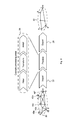
- Fig. 1 the topology of the network 2 is illustrated as a graph comprising nodes 4a, 4b, etc., the nodes communicating with each other, as, for example, illustrated by a solid line representing a communication link 6a.
- the communication link 6a is characterized by at least one characteristic of the communication between the nodes 4a and 4b.
- Fig. 1 furthermore illustrates an example of three applications 8a to 8c which require information on the topology of the network 2 in order to perform their services.
- a network topology processing system 10 is illustrated in Fig. 1 , comprising a network input interface 10a operable to receive topological network information related to a characteristic of a communication within the communication network.
- the network input interface 10a may, for example, retrieve the topological network information or the topology data from the network devices or the nodes 4a to 4m directly or, alternatively or additionally, utilize network monitoring devices, as for example the network monitoring device 12.
- the network topology analyzer 10 furthermore comprises an analyzer 10b in order to process or transform the received topological network information and to provide information on the topology of the network via an output interface 10c of the topology analyzer 10 which may be accessed by the network topology aware applications 8a to 8c.
- Fig. 1 gives a high-level overview of a topology of a communications network and associated topology processing. It depicts a network topology exposure system. Its first important component is a data gathering component, which retrieves network topology data from the network devices, e. g., routers or routing protocol monitors. This can be, for instance, a network management system, or route analytics software.
- a graph processing pipeline that processes the topology data is illustrated in Fig. 1 , so that it can be exported to and used by a network-aware application. Examples for such a network topology-aware system are CDNs or distributed clouds. For the invention is not relevant how the information is internally distributed by a user of the topology processing pipeline.
- FIG. 1 illustrates a network environment and the associated network nodes and communication links between the network nodes used to represent a topology of a communication network schematically
- an embodiment of an inventive network topology analyzer suitable to operate on a network topology as illustrated in Fig. 1 is shown in Fig. 2 .
- An embodiment of a network topology analyzer 20 comprises a network input interface 22, a user input interface 24 and an analyzer 26.
- the network input interface 22 is operable to receive topological network information related to a characteristic of a communication within the communication network, for example according to the techniques described above with respect to the input interface 10a of Fig. 1 .
- the input interface 22 may, for example, receive topological network information related to the representation of topology 30 illustrated on the left-hand side of Fig. 2 .
- Topological network information may, for example, also be denoted as a graph, the terminology representing the illustration of the network as used herein, wherein individual nodes are connected by straight lines in order to signal that the two nodes connected by a line are communicating directly with each other in the particular representation of the network.
- Each communication link has associated thereto at least one characteristic, such as, for example, a delay, a bandwidth, routing costs or the like.
- the topological network information is used as an input for the analyzer 26 which is operable to provide required information on the topology of the network, as it may be achieved by a transformation of the topology 30 of the network provided to the input interface 22.
- a transformation or a visualization of the required information on the topology of a communication network 32 is illustrated on the right side of the network topology analyzer 20, that is, at an output interface 28 of the same.
- the network topology analyzer 20 provides at its output 28 information on the topology of a communication network 32 which may, just as an example, be a further graph of the topology in which individual nodes have been filtered out according to some filter characteristics.
- the network topology analyzer 20 further comprises a user input interface 24 which is operable to receive user preference information or user specific rules, the user preference information being indicative of a topology representation requested by the user. That is, according to the embodiments of the present invention, the processing of the topological network information by the analyzer 26 can be influenced or configured by a user via the user input interface 24 so that the representation 32 as output by the network topology analyzer may correspond to required information on a topology of the communication network.
- topology of the network is illustrated by a graph within this specification, the embodiments of the present invention are by no means understood to be restricted to the provision of a graph or the like. To the contrary, all possible illustrations or representations of information on a topology of a communication network may be provided at an output 28 of a network topology analyzer.
- the analyzer comprises a processing pipeline consisting of numerous modules, as for example modules 26a to 26c illustrated in Fig. 1 , which consecutively process or transform topological network information in order to arrive at the required information on the topology of the communication network at an output of the pipeline, i.e. at an output of the analyzer 26.
- modules 26a to 26c illustrated in Fig. 1
- Particular ways to modify or configure the processing of the analyzer are, for example, changing the processing order of the modules 26a to 26c, providing user-defined scripts, defining a particular processing of the topological network information within one of the modules or within the whole pipeline, providing configuration parameters for a predetermined processing scheme or filter, selecting one of a group of predetermined processing schemes or the like.
- FIG. 2 illustrates how programmability may be achieved in the pipeline.
- a user can decide about the execution order and parameterization of pipeline components.
- the user can create of modify one or more modules so that it process the network topology according to its needs, e. g., according to user-specific rules.
- the former method may be easier to use, while the latter approach may allow more flexibility.
- An embodiment of the invention may decide only to implement one of both variants.
- the objective may be to set up a pipeline that extracts the view that is needed or desired by a given user from a given in-put network topology.
- Fig. 3 illustrates a particular example how a pipeline may process data or metadata that is specific for a topology of a communication network. For instance, if an application such as a CDN only has sites at a subset 40a to 40f of the nodes inside a network topology, or if a VPN only maps to a subset 40a to 40f of the network graph, only the subset 40a to 40f of the network topology given by such metadata may be of concern. In such a case, an important processing step of the graph processing pipeline of an analyzer 26 may be to filter out the relevant part of the network topology and to present it to the user (which could be the CDN, the VPN customer, or any overlay application) in an adapted way.
- an important processing step of the graph processing pipeline of an analyzer 26 may be to filter out the relevant part of the network topology and to present it to the user (which could be the CDN, the VPN customer, or any overlay application) in an adapted way.
- network topology may be represented as a graph and processed by several, modular, concatenated components. Each component can be subdivided recursively into further processing steps, which could also include processing loops (not shown).
- a typical processing pattern for network topology abstraction is to filter out a relevant part of the network topology (e. g., all nodes that matter for a CDN), to transform the graph subsequently (e. g., remove all other nodes), and to adapt the result according to the needs (e.g., to re-calculate or normalize the performance costs between the remaining nodes).
- Some key principles of the graph processing pipeline as illustrated in Fig. 3 may be modularity and re-usability of components. It is important to emphasize that the pipeline is not necessarily executed once only. The pipeline is also executed if the network topology changes, in order to dynamically adapt the output according to the actual network state.
- FIG. 4 A particular implementation of an embodiment of the present invention is illustrated in Fig. 4 , where processing or computational power of the analyzer 26 may be saved in a multi-user environment.
- the user input interface receives user preference information for, at least, a first user 42 and a second user 44.
- the analyzer is able to employ "forking" within the processing pipeline, that is, to provide the output of a first module 26a of the pipeline to both the second module 26b and the third module 26c in order to avoid possibly redundant processing or filtering of the topological information.
- Fig. 4 depicts how the system may deal with multi-user environments.
- user 42 and user 44 can obtain different views on or representations of the same network topology 30.
- the pipelines result in two entirely different graphs, with different edges (solid lines indicating communication links), vertices (nodes), labels, and cost values assigned to edges.
- This is visualized by two different graphs in that Fig. 4 , each representing a different information on the topology of the network.
- the graph processing pipelines of different users share certain initial processing steps, because they have then to be calculated only once.
- forking This is achieved by configurable or automatically performed "forking" actions inside the pipeline, which duplicates the outcome of a pipeline processing step to create input to two or more follow-up modules of a pipeline.
- the forking may be also caused by considering application, domain or user-specific metadata.
- Fig. 5 illustrates in a schematic view how programmability of a particular module or of a complete analyzer, that is, of the processing pipeline, may be achieved in practice, so as to allow for different orders of modules within a pipeline.
- Fig. 5 gives a first overview of a possible internal realization of a graph processing pipeline in an analyzer 26. It consists of several components or modules 26a, 26b and 26c that execute a certain step. Each component consists of a well-defined interface, most notably, for reading and writing the data representing a network topology. The data is exchanged between subsequent pipeline steps by an appropriate interface. In a more complex embodiment of the invention, this data may, for example, be copied or stored in a database management system 50.
- Fig. 6 details the interfaces of a processing step or a module in the pipeline, in this example for module 26b.
- the input of each step may be retrieved from the data base 50.
- the functions and algorithms of one module may change data in the data base 50 as well, subject to data access rules etc.
- the output of one module may be written to the data base 50 as well.
- This kind of logically centralized data storage may facilitate consistency checks, read/write access policies, caching, and error handling.
- data base storage 50 may enable roll-back of one or more processing steps failed.
- the database storage may also be beneficial for reusing data among several pipelines (e. g., for different users), as illustrated in Fig. 6 .
- Fig. 7 provides a high-level overview how programmability may be achieved.
- Either a script 52 or (uncompiled/compiled) program code may be loaded into a pipeline processing, after it has been configured and stored by the user accordingly.
- the user may have implemented therein a certain data processing function that needs to be executed. That processing might use also functions in a library, e. g., for commonly used algorithms. That concept may be applied to scripts or programs written in any programming or scripting language, including, for example, Java, Python, Groovy, JavaScript, Perl, etc.
- Fig. 8 sketches more in detail some important functions required for programmability.
- the script or program realizing user-specific functions inside the pipeline may run inside a run-time environment ("sandbox"), using an interpreter or a compiler (e.g. a just-in-time compiler).
- a compiler e.g. a just-in-time compiler.
- two (optional) initialization and verification/validation scripts 60a and 60b may be integrated.
- the logic in those functions may be a script itself. However, unlike the actual user-specific processing, this logic may be under control of the operator of the overall system, and not by the user. That is, the scripts may, for example, implement an evaluation of the user preference information and/or the requested topology representation with respect to a security policy. This enables e. g. the network provider to ensure that users of the pipeline only get a filtered, consistent view inside what they can program (“initialization”), while it is also possible to perform consistency and error checks (“verification/validation”) on the result of the script, in order to prevent an invalid outcome.
- the script or program code may be provided via a provisioning and configuration system, which can e.g. be coupled with a portal 62 of the network provider, enabling each user to configure the pipeline, or parts of the pipeline, according to its needs.
- a provisioning and configuration system which can e.g. be coupled with a portal 62 of the network provider, enabling each user to configure the pipeline, or parts of the pipeline, according to its needs.
- Embodiments of the invention may further include a dedicated exception and error handling system 64 in order to deal with exceptions inside the user-specified code. It may separate different classes of exceptions. Some of them may require internal handling by the user-specified code, while others may affect the pipeline module or the pipeline as a whole (e. g., if the graph cannot be processed at all by the script).
- interfaces may be provided to a representation generator 66 and for logging 68. In particular that information might also be exposed to users via a portal.
- the representation generator may also be referred to as a graph storage in some embodiments in which the information on a topology of a communication network is provided as a graph.
- Fig. 9 illustrates a part of the operation within a message-sequence-chart.
- the pipeline or the analyzer is triggered when input data 70 is available.
- a run-time environment 72 may then execute (optional) initialization steps 74 to ensure that the user-specified script runs appropriately.
- the user-provided script 76 is executed, which will typically process and modify the network topology data.
- the outcome is then validated by another (optional) verification step 78.
- these steps may be repeated in subsequent pipeline modules, if needed.
- Fig. 10 again illustrates an embodiment of a method for providing required information on a topology of a communication network as a flow chart.
- topological network information related to a characteristic of a communication within the communication network is received.
- a user preference information is received, the user preference information being indicative of a topology representation requested by the user.
- an output step 84 the required information on the topology of the network is provided, the providing comprising processing the topological network information based on the user preference information.
- the network topology gathering system i.e. the network topology analyzer
- the network topology-aware system could be a CDN or a distributed cloud management system. It can also be an ALTO server that exposes the network topology to other applications by the ALTO interface.
- the topology processing pipeline processes the input data from the former system and provides it to the latter system.
- a rudimentary pipeline is a solution for some use cases. Yet, the key benefits of this invention may be of maximum use in more complex embodiments. For instance, more than one user may require topology information, but with different requirements and constraints.
- One such user could be a CDN, another user could be a distributed cloud system.
- Further users may be (operator-internal) traffic engineering or capacity planning applications, or (operator-external) traffic optimization tools, e. g., for peer-to-peer applications. All those users may need a different view on the network topology (and might also be provided different access rights by the operator). This implies that each user may have its own topology processing pipeline that provides the appropriate view, and possibly recalculates this view if the network dynamically changes.
- An actual embodiment of the graph pipeline can be realized by a software program, e. g., written in Java.
- the pipeline and its internal modules could be objects in a class hierarchy.
- the storage of the network topology data could be realized in the program memory.
- An alternative would be a data base management system, which offers persistent storage, transactions, roll-back, etc.
- the script may be written in a high-level programming or scripting language, including Java, Python, Groovy, JavaScript, Perl, etc. This enables users to customize and program the pipeline according to their needs.
- the system may also offer a set of pre-defined library calls to facilitate important and frequently used tasks.
- an example for an actual script that can be used in the system shown in Fig. 7 and 8 is listed below as a pseudo code. It represents a function that normalizes edge costs into a given range.
- the example assumes that the topology abstraction pipeline supports Groovy code and implements a specific software interface to provide access to the graph data.
- the actual function shown in this example is just one of an arbitrary number of possible implementations and merely provided to illustrate a function that a user may need, but that might not be available in that form in any given system at design time.
- Groovy script implementation
- This invention addresses the question how to provide different, application-specific views on a network topology. For instance, even if a CDN and a cloud computing platform run inside the network of a service provider, their operation will not need the same information and the same level-of-detail, because they will not necessarily run at the same sites, and they may have different optimization objectives. This implies that the network provider has to provide multiple views of its network topology to different applications and/or users.
- this invention provides a programmable graph processing pipeline, which can be configured and modified at run-time and thus enables user-specific abstraction levels for a network topology.
- the "user” that programs the system may be the service provider itself, e. g., a part of the same organization.
- the processing pipeline is then a way to customize the topology exposure system according to the needs of its customers. It is also possible, but more challenging, to offer this programmability as a feature to third-parties outside the administrative domain. Thereby would enable customers of a service provider to control how topology and monitoring data is processed and exported to them, eventually within constraints imposed by the service provider.
- An example use case would be to program a topology exposure for a Virtual Private Network (VPN) that represents a customer-specific slice of the service provider network.
- VPN Virtual Private Network
- OTT Over-The-Top
- This invention proposes a method that enables user-specific processing and exposure of network topology information. This programmability may provide several key advantages.
- a first advantage is flexibility and openness.
- a graph processing pipeline with programmable components enables very different network topology processing algorithms.
- the algorithms and or policies do not have to be specified at design/compile time, but can be changed afterwards.
- arbitrary processing steps can be integrated and adapted to the needs of specific networks.
- a second advantage is customization.
- the solution enables different users of a network (e. g., different customers, such as a CDN and a cloud system, or different instances of a CDN) to control how data is gather, process, and exported.
- a network e. g., different customers, such as a CDN and a cloud system, or different instances of a CDN
- Each user can define its own scripts, and gets a corresponding view on the network. Due to the modular structure of the topology processing pipelines, users can re-use existing functions and augment them with customized scripts according to their needs.
- the system architecture includes initialization, verification and validation steps that ensure data sanity, i. e., that the system produces a valid result.
- a third advantage is usability. Many network administrators can be assumed to understand a high-level programming language and should thus be able to use the system. Existing software development tools such as integrated development environments can be used directly, or adapted accordingly. This results in a low barrier for new users to use the system.
- Functional blocks denoted as "means for " shall be understood as functional blocks comprising circuitry that is adapted for performing a certain function, respectively.
- a "means for s.th.” may as well be understood as a “means being adapted or suited for s.th.”.
- a means being adapted for performing a certain function does, hence, not imply that such means necessarily is performing said function (at a given time instant).
- any functional blocks labeled as “means”, “means for .", “.", etc. may be provided through the use of dedicated hardware, such as “... “, “... “, “a processor”, “a controller”, etc. as well as hardware capable of executing software in association with appropriate software.
- any entity described herein as “means” may correspond to or be implemented as “one or more modules", “one or more devices”, “one or more units”, etc.
- the functions may be provided by a single dedicated processor, by a single shared processor, or by a plurality of individual processors, some of which may be shared.
- processor or “controller” should not be construed to refer exclusively to hardware capable of executing software, and may implicitly include, without limitation, digital signal processor (DSP) hardware, network processor, application specific integrated circuit (ASIC), field programmable gate array (FPGA), read only memory (ROM) for storing software, random access memory (RAM), and nonvolatile storage.
- DSP digital signal processor
- ASIC application specific integrated circuit
- FPGA field programmable gate array
- ROM read only memory
- RAM random access memory
- nonvolatile storage nonvolatile storage.
- Other hardware conventional and/or custom, may also be included.
- any block diagrams herein represent conceptual views of illustrative circuitry embodying the principles of the invention.
- any flow charts, flow diagrams, state transition diagrams, pseudo code, and the like represent various processes which may be substantially represented in computer readable medium and so executed by a computer or processor, whether or not such computer or processor is explicitly shown.
- each claim may stand on its own as a separate embodiment. While each claim may stand on its own as a separate embodiment, it is to be noted that - although a dependent claim may refer in the claims to a specific combination with one or more other claims - other embodiments may also include a combination of the dependent claim with the subject matter of each other dependent claim. Such combinations are proposed herein unless it is stated that a specific combination is not intended. Furthermore, it is intended to include also features of a claim to any other independent claim even if this claim is not directly made dependent to the independent claim.
- a single step may include or may be broken into multiple sub steps. Such sub steps may be included and part of the disclosure of this single step unless explicitly excluded.
Landscapes
- Engineering & Computer Science (AREA)
- Computer Networks & Wireless Communication (AREA)
- Signal Processing (AREA)
- Data Exchanges In Wide-Area Networks (AREA)
Priority Applications (2)
| Application Number | Priority Date | Filing Date | Title |
|---|---|---|---|
| EP13305091.4A EP2760160A1 (fr) | 2013-01-25 | 2013-01-25 | Fourniture d' informations adaptées sur une topologie d'un réseau de communication |
| PCT/EP2014/050748 WO2014114546A1 (fr) | 2013-01-25 | 2014-01-16 | Présentation d'informations adaptées sur la topologie d'un réseau de communication |
Applications Claiming Priority (1)
| Application Number | Priority Date | Filing Date | Title |
|---|---|---|---|
| EP13305091.4A EP2760160A1 (fr) | 2013-01-25 | 2013-01-25 | Fourniture d' informations adaptées sur une topologie d'un réseau de communication |
Publications (1)
| Publication Number | Publication Date |
|---|---|
| EP2760160A1 true EP2760160A1 (fr) | 2014-07-30 |
Family
ID=47715947
Family Applications (1)
| Application Number | Title | Priority Date | Filing Date |
|---|---|---|---|
| EP13305091.4A Withdrawn EP2760160A1 (fr) | 2013-01-25 | 2013-01-25 | Fourniture d' informations adaptées sur une topologie d'un réseau de communication |
Country Status (2)
| Country | Link |
|---|---|
| EP (1) | EP2760160A1 (fr) |
| WO (1) | WO2014114546A1 (fr) |
Cited By (5)
| Publication number | Priority date | Publication date | Assignee | Title |
|---|---|---|---|---|
| WO2016053301A1 (fr) * | 2014-09-30 | 2016-04-07 | Hewlett Packard Enterprise Development Lp | Gestion basée sur la topologie, utilisant des politiques à étapes et versions |
| WO2016053304A1 (fr) * | 2014-09-30 | 2016-04-07 | Hewlett Packard Enterprise Development Lp | Gestion basée sur la topologie, avec politiques de conformité |
| US9507932B2 (en) | 2014-09-12 | 2016-11-29 | Alcatel Lucent | Policy enforcement in a topology abstraction system |
| US9667499B2 (en) | 2014-09-12 | 2017-05-30 | Alcatel Lucent | Sparsification of pairwise cost information |
| EP3510493A4 (fr) * | 2016-09-12 | 2020-02-26 | Illumio, Inc. | Représentation de serveurs dans un système de gestion d'informations de réseau distribuées permettant un regroupement efficace d'informations |
Families Citing this family (1)
| Publication number | Priority date | Publication date | Assignee | Title |
|---|---|---|---|---|
| CN108777649B (zh) * | 2018-06-06 | 2023-05-30 | 山东易码智能科技股份有限公司 | 一种网络侦听装置、系统及方法 |
Citations (3)
| Publication number | Priority date | Publication date | Assignee | Title |
|---|---|---|---|---|
| WO2004010631A2 (fr) * | 2002-07-19 | 2004-01-29 | Masergy Communications | Configuration automatisee de reseau a acheminement par paquets |
| WO2008024976A2 (fr) * | 2006-08-25 | 2008-02-28 | Pradeep Singh | Inférence de connectivité parmi des segments de réseau en l'absence d'informations de configuration |
| EP2466832A1 (fr) * | 2010-12-16 | 2012-06-20 | Openet Telecom Ltd. | Procédés, systèmes et dispositifs de routage à base de contexte dynamique utilisant un arbre de topologie |
-
2013
- 2013-01-25 EP EP13305091.4A patent/EP2760160A1/fr not_active Withdrawn
-
2014
- 2014-01-16 WO PCT/EP2014/050748 patent/WO2014114546A1/fr active Application Filing
Patent Citations (3)
| Publication number | Priority date | Publication date | Assignee | Title |
|---|---|---|---|---|
| WO2004010631A2 (fr) * | 2002-07-19 | 2004-01-29 | Masergy Communications | Configuration automatisee de reseau a acheminement par paquets |
| WO2008024976A2 (fr) * | 2006-08-25 | 2008-02-28 | Pradeep Singh | Inférence de connectivité parmi des segments de réseau en l'absence d'informations de configuration |
| EP2466832A1 (fr) * | 2010-12-16 | 2012-06-20 | Openet Telecom Ltd. | Procédés, systèmes et dispositifs de routage à base de contexte dynamique utilisant un arbre de topologie |
Cited By (7)
| Publication number | Priority date | Publication date | Assignee | Title |
|---|---|---|---|---|
| US9507932B2 (en) | 2014-09-12 | 2016-11-29 | Alcatel Lucent | Policy enforcement in a topology abstraction system |
| US9667499B2 (en) | 2014-09-12 | 2017-05-30 | Alcatel Lucent | Sparsification of pairwise cost information |
| WO2016053301A1 (fr) * | 2014-09-30 | 2016-04-07 | Hewlett Packard Enterprise Development Lp | Gestion basée sur la topologie, utilisant des politiques à étapes et versions |
| WO2016053304A1 (fr) * | 2014-09-30 | 2016-04-07 | Hewlett Packard Enterprise Development Lp | Gestion basée sur la topologie, avec politiques de conformité |
| CN107005421A (zh) * | 2014-09-30 | 2017-08-01 | 慧与发展有限责任合伙企业 | 利用阶段和版本策略的基于拓扑的管理 |
| US11228497B2 (en) | 2014-09-30 | 2022-01-18 | Micro Focus Llc | Topology based management with stage and version policies |
| EP3510493A4 (fr) * | 2016-09-12 | 2020-02-26 | Illumio, Inc. | Représentation de serveurs dans un système de gestion d'informations de réseau distribuées permettant un regroupement efficace d'informations |
Also Published As
| Publication number | Publication date |
|---|---|
| WO2014114546A1 (fr) | 2014-07-31 |
Similar Documents
| Publication | Publication Date | Title |
|---|---|---|
| US11489738B2 (en) | Microservices application network control plane | |
| EP2760160A1 (fr) | Fourniture d' informations adaptées sur une topologie d'un réseau de communication | |
| US10681006B2 (en) | Application-context-aware firewall | |
| US8813209B2 (en) | Automating network reconfiguration during migrations | |
| US9537717B2 (en) | Policy enforcement point provisioning | |
| US9935841B2 (en) | Traffic forwarding for processing in network environment | |
| CN105074692A (zh) | 使用基于逻辑多维标签的策略模型的分布式网络管理系统 | |
| US11240174B2 (en) | Systems and methods for intelligent application grouping | |
| US11929890B2 (en) | Microservices application network control plane | |
| US11675638B1 (en) | Webhooks use for a microservice architecture application | |
| WO2004097556A2 (fr) | Systeme hierarchique de gestion de services | |
| US20240056420A1 (en) | Network connectivity policy management system | |
| Rygielski et al. | Model-based throughput prediction in data center networks | |
| US11375033B1 (en) | Automated tuning of network intermediary devices | |
| US20220173963A1 (en) | Heterogeneous cross-cloud service interoperability | |
| Clayman et al. | Experimenting with control operations in software-defined infrastructures | |
| Bagheri et al. | Automating the Translation of Cloud Users' High-Level Security Needs to an Optimal Placement Model in the Cloud Infrastructure | |
| DeJonghe et al. | Application Delivery and Load Balancing in Microsoft Azure | |
| US20230325478A1 (en) | Instrumenting applications to prevent abuse by privileged users | |
| Wang et al. | Providing survivability for virtual networks against substrate network failure |
Legal Events
| Date | Code | Title | Description |
|---|---|---|---|
| PUAI | Public reference made under article 153(3) epc to a published international application that has entered the european phase |
Free format text: ORIGINAL CODE: 0009012 |
|
| 17P | Request for examination filed |
Effective date: 20131017 |
|
| AK | Designated contracting states |
Kind code of ref document: A1 Designated state(s): AL AT BE BG CH CY CZ DE DK EE ES FI FR GB GR HR HU IE IS IT LI LT LU LV MC MK MT NL NO PL PT RO RS SE SI SK SM TR |
|
| AX | Request for extension of the european patent |
Extension state: BA ME |
|
| RAP1 | Party data changed (applicant data changed or rights of an application transferred) |
Owner name: ALCATEL LUCENT |
|
| RBV | Designated contracting states (corrected) |
Designated state(s): AL AT BE BG CH CY CZ DE DK EE ES FI FR GB GR HR HU IE IS IT LI LT LU LV MC MK MT NL NO PL PT RO RS SE SI SK SM TR |
|
| STAA | Information on the status of an ep patent application or granted ep patent |
Free format text: STATUS: EXAMINATION IS IN PROGRESS |
|
| 17Q | First examination report despatched |
Effective date: 20170217 |
|
| STAA | Information on the status of an ep patent application or granted ep patent |
Free format text: STATUS: THE APPLICATION IS DEEMED TO BE WITHDRAWN |
|
| 18D | Application deemed to be withdrawn |
Effective date: 20170628 |