EP2760037A1 - Electrical system lock out switch - Google Patents
Electrical system lock out switch Download PDFInfo
- Publication number
- EP2760037A1 EP2760037A1 EP14153095.6A EP14153095A EP2760037A1 EP 2760037 A1 EP2760037 A1 EP 2760037A1 EP 14153095 A EP14153095 A EP 14153095A EP 2760037 A1 EP2760037 A1 EP 2760037A1
- Authority
- EP
- European Patent Office
- Prior art keywords
- lock out
- electrical switch
- out mechanism
- shaft
- hole
- Prior art date
- Legal status (The legal status is an assumption and is not a legal conclusion. Google has not performed a legal analysis and makes no representation as to the accuracy of the status listed.)
- Granted
Links
Images


Classifications
-
- H—ELECTRICITY
- H01—ELECTRIC ELEMENTS
- H01H—ELECTRIC SWITCHES; RELAYS; SELECTORS; EMERGENCY PROTECTIVE DEVICES
- H01H9/00—Details of switching devices, not covered by groups H01H1/00 - H01H7/00
- H01H9/20—Interlocking, locking, or latching mechanisms
- H01H9/28—Interlocking, locking, or latching mechanisms for locking switch parts by a key or equivalent removable member
- H01H9/286—Interlocking, locking, or latching mechanisms for locking switch parts by a key or equivalent removable member making use of a removable locking part acting directly on the operating part
-
- H—ELECTRICITY
- H01—ELECTRIC ELEMENTS
- H01H—ELECTRIC SWITCHES; RELAYS; SELECTORS; EMERGENCY PROTECTIVE DEVICES
- H01H13/00—Switches having rectilinearly-movable operating part or parts adapted for pushing or pulling in one direction only, e.g. push-button switch
- H01H13/02—Details
- H01H13/12—Movable parts; Contacts mounted thereon
- H01H13/14—Operating parts, e.g. push-button
-
- H—ELECTRICITY
- H01—ELECTRIC ELEMENTS
- H01H—ELECTRIC SWITCHES; RELAYS; SELECTORS; EMERGENCY PROTECTIVE DEVICES
- H01H71/00—Details of the protective switches or relays covered by groups H01H73/00 - H01H83/00
- H01H71/04—Means for indicating condition of the switching device
-
- H—ELECTRICITY
- H01—ELECTRIC ELEMENTS
- H01H—ELECTRIC SWITCHES; RELAYS; SELECTORS; EMERGENCY PROTECTIVE DEVICES
- H01H71/00—Details of the protective switches or relays covered by groups H01H73/00 - H01H83/00
- H01H71/06—Distinguishing marks, e.g. colour coding
-
- H—ELECTRICITY
- H01—ELECTRIC ELEMENTS
- H01H—ELECTRIC SWITCHES; RELAYS; SELECTORS; EMERGENCY PROTECTIVE DEVICES
- H01H71/00—Details of the protective switches or relays covered by groups H01H73/00 - H01H83/00
- H01H71/10—Operating or release mechanisms
- H01H71/50—Manual reset mechanisms which may be also used for manual release
- H01H71/58—Manual reset mechanisms which may be also used for manual release actuated by push-button, pull-knob, or slide
-
- H—ELECTRICITY
- H01—ELECTRIC ELEMENTS
- H01H—ELECTRIC SWITCHES; RELAYS; SELECTORS; EMERGENCY PROTECTIVE DEVICES
- H01H73/00—Protective overload circuit-breaking switches in which excess current opens the contacts by automatic release of mechanical energy stored by previous operation of a hand reset mechanism
- H01H73/02—Details
- H01H73/16—Distinguishing marks, e.g. colour coding
-
- H—ELECTRICITY
- H01—ELECTRIC ELEMENTS
- H01H—ELECTRIC SWITCHES; RELAYS; SELECTORS; EMERGENCY PROTECTIVE DEVICES
- H01H9/00—Details of switching devices, not covered by groups H01H1/00 - H01H7/00
- H01H9/16—Indicators for switching condition, e.g. "on" or "off"
Abstract
Description
- Exemplary embodiments of this invention generally relate to electrical actuation systems and, more particularly, to a lock-out solution for an electrical actuation system of an aircraft.
- During installation, service and maintenance of powered equipment, service personnel, such as electricians for example, must assure that the equipment being worked on is isolated from its power source. Although the power source is usually electrical, other power sources such as mechanical, hydraulic, pneumatic, chemical, and thermal may be involved.
- When the power source and the equipment are arranged generally at the same location, isolation is not difficult. However, it is common that the power source, e.g. a breaker box, is located relatively far away from the equipment in need of service. Thus, it is possible that after the equipment is isolated at the power source it may be inadvertently powered on by other personnel who do not know that the equipment was intentionally powered off.
- "Lock-out" and "Tag-out" refer to safe methods for the complete power isolation of equipment during maintenance or service work. OSHA regulations require the use of locks or tags at control points, such as breaker boxes for example, as warning devices to ensure that personnel are not injured from accidental machine start-ups. While many lock-out and tag-out solutions perform well, none are fool proof. For example, tag-out solutions assume that all personnel can read the same language. Lock-out solutions are often difficult to install and require that the device being locked is pre-equipped with a lock receiving apparatus. In addition, lock-out solutions may be bypassed intentionally or accidentally without the knowledge of the affected personnel.
- As aircraft manufacturers convert systems previously using hydraulic controls to new electrical solutions, issues arise in preventing unintended start-up of equipment. Many of these systems on an aircraft have large moving surfaces that can create a safety hazard if they were to accidentally move while maintenance personnel are working on them or a neighboring engine. Hydraulic lockout valves were previously used in the hydraulic lines to prevent fluid flow, and therefore movement of these large surfaces. Because these systems are now electrically actuated, an electrical lock out mechanism configured to safely lock out the system by removing power is desired.
- According to one embodiment of the invention, an electrical switch for use in an electrical actuation system is provided including a switch box having an upper surface with an opening. A stem guide is coupled to the switch box adjacent the opening. A lock out mechanism is received within a central bore of the stem guide and the opening. The lock out mechanism is configured to move between a first position and a second position to selectively break a flow of power through the electrical switch. A pin is configured to couple the lock out mechanism to the stem guide in one of the first position or the second position.
- According to another embodiment of the invention, an electrical actuation system of an aircraft is provided including a power feed line configured to supply power to at least one downstream component. An electrical switch is arranged along a portion of the power feed line. The electrical switch includes a switch box having an upper surface with an opening. A stem guide is coupled to the switch box adjacent the opening. A lock out mechanism is received within a central bore of the stem guide and the opening. The lock out mechanism is configured to move between a first position and a second position to selectively break a flow of power in the power feed line. A pin is configured to couple the lock out mechanism to the stem guide in one of the first position or the second position.
- The subject matter, which is regarded as the invention, is particularly pointed out and distinctly claimed in the claims at the conclusion of the specification. The foregoing and other features, and advantages of the invention are apparent from the following detailed description taken in conjunction with the accompanying drawings in which:
-
FIG. 1 is a perspective view of an electrical switch in an electrical actuation system of an aircraft according to an embodiment of the invention; -
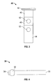
FIG. 2 is a perspective view of an electrical switch in an electrical actuation system of an aircraft according to an embodiment of the invention; -
FIG. 3 is a front view of a lock out mechanism of the electrical switch ofFIGS. 1 and2 according to an embodiment of the invention; and -
FIG. 4 is a side view of a pin of the electrical switch ofFIGS. 1 and2 according to an embodiment of the invention. - The detailed description explains embodiments of the invention, together with advantages and features, by way of example with reference to the drawings.
- Referring now to the FIGS., an
electrical switch 20, such as from an electrically actuated thrust reverser system or an electrically actuated variable area nozzle system of an aircraft is illustrated. In the illustrated embodiment, theelectrical switch 20 is a three pole single throw switch (3PST) having an auxiliary switch for position status. Alternative electrical switches, such as a four pole single throw switch (4PST) that uses the fourth pole for position status for example, are within the scope of the invention. Configured to be mounted to a panel (not shown) in a conventional manner, theelectrical switch 20 is arranged within a power feed line of the electrical actuation system and supplies power to a downstream component of the actuation system, such as a motor for example. - A
stem guide 30 having acentral bore 32 is aligned with and positioned next to an opening (not shown) in theupper surface 24 of theswitch box 22. In one embodiment, thestem guide 30 is threadably coupled, such as with amounting nut 31 for example, to a portion of theswitch box 22 extending perpendicularly from theupper surface 24 adjacent the opening. In addition, thestem guide 30 includes a throughhole 34 configured to receive apin 36. - The
electrical switch 20 additionally includes a lock outmechanism 40 configured to selectively create a break in the power feed line. In the illustrated, nonlimiting embodiment, the lock outmechanism 40 is a generally cylindrical stem having abutton feature 42 and ashaft 44; however, alternative configuration, such as including a lock out mechanism that pivots for example, are within the scope of the invention. Afirst portion 46 of theshaft 44, positioned next to thebase 42, includes a first color, such as green for example, and an adjacentsecond portion 48 of theshaft 44 includes a second color, distinct from the first color, for example red. Theshaft 44 additionally includes a first throughhole 50 and a second through hole 52 (FIG. 3 ). In one embodiment, the first throughhole 50 is arranged within thesecond portion 48 of theshaft 44, and the second throughhole 52 is arranged near thesecond portion 48 of theshaft 44, opposite thefirst portion 46. The first throughhole 50 and the second throughhole 52 may be substantially similar in size to the throughhole 34 of thestem guide 30. - The
shaft 44 of the lock outmechanism 40 is slidably positioned within thebore 32 of thestem guide 30, as well as the opening in theupper surface 24 of theswitch box 22. In the illustrated embodiment, the lock outmechanism 40 is configured to translate about an axis X between a first position (FIG. 1 ) and a second position (FIG. 2 ) to alter an operational mode of theelectrical switch 20. Theshaft 44 of the lock outmechanism 40 is arranged within thebore 32 of thestem guide 30 such that the first and second throughholes shaft 44 are substantially parallel to the throughhole 34 of thestem guide 30. When the lock outmechanism 40 is in either the first position or the second position, one of the first throughhole 50 and the second throughhole 52 is arranged generally coaxially with the throughhole 34 of thestem guide 30. - Similar to the
through hole 34 of thestem guide 30, the first and second throughholes 50 of the lock outmechanism 40 are also configured to receive thepin 36. Therefore, the diameter of thepin 36 is generally smaller than the diameter of each of the throughholes pin 36 is configured to couple theshaft 44 of the lock outmechanism 40 to thestem guide 30 to retain the lock outmechanism 40 in a desired position relative to theswitch box 22. In one embodiment, asnap ball 58 is located adjacent afirst end 54 of thepin 36 to prevent unintended movement of thepin 36 once inserted through thestem guide 30 and lock out mechanism 40 (FIG. 4 ). Thesecond end 56 of thepin 36 may be coupled to aretaining assembly 60 configured to limit movement of thepin 36 relative to theswitch box 22. The illustratedretaining assembly 60 includes aring 62 coupled to thesecond end 56 of thepin 36, and awasher 64 arranged about the lock outmechanism 40, such as between theupper surface 24 of theswitch box 22 and themounting nut 31 for example. A lanyard orcable 66, for example made of stainless steel, couples thering 62 and the fixedwasher 64. A sufficient length ofcable 66 is provided such that insertion and removal of thepin 36 from thestem guide 30 and lock outmechanism 40 are not inhibited. - When the lock out
mechanism 40 is in the first position, as illustrated inFIG. 1 , thepin 36 extends through thehole 34 of thestem guide 30 as well as the aligned first throughhole 50 of theshaft 44 of the lock outmechanism 40. In this first position, only thefirst portion 46 of theshaft 44 having a first color is visible outside theelectrical switch 20. In one embodiment, when in the first position, the lock outmechanism 40 indicates that the electrical switch is operating normally and that power from the power feed line is actively flowing through theelectrical switch 20 to at least one downstream component. - In the second position, as illustrated in
FIG. 2 , thepin 36 is arranged within the aligned throughhole 34 of thestem guide 30 and the second through hole (not shown) of theshaft 44 of the lock outmechanism 40. In the second position, both thefirst portion 46 and thesecond portion 48, and therefore the first color and second color of theshaft 44 are visible outside theelectrical switch 20. In one embodiment, when in the second position, the lock outmechanism 40 indicates that theelectrical switch 20 is in a safety mode and that the power feed line has been broken so that no power is being supplied through the electrical switch to downstream components. - To move the lock out
mechanism 40 between the first position and the second position, a mechanic removes thepin 36 from thestem guide 30 andshaft 44 of the lock outmechanism 40 and then applies a force to the lock outmechanism 40. Once reaching the new position, thepin 36 is positively reinserted through thestem guide 30 and the lock outmechanism 40. In one embodiment, a mechanic pulls the lock outmechanism 40 to move the lock outmechanism 40 from the first position to the second position, and pushes the lock outmechanism 40 to move the lock outmechanism 40 from the second position to the first position. - The
electrical switch 20 includes an electrical lock outmechanism 40 for use in an electrically actuated system of an aircraft. The color coding of the lock outmechanism 40 will easily indicate to a mechanic if theswitch 20 is either in normal mode operation or safety mode operation. By including a snap ball at anend 54 of thepin 36, thepin 36 positively retains the lock outmechanism 40 in a position. The positive locking pin provides a visible locking feature - While the invention has been described in detail in connection with only a limited number of embodiments, it should be readily understood that the invention is not limited to such disclosed embodiments. Rather, the invention can be modified to incorporate any number of variations, alterations, substitutions or equivalent arrangements not heretofore described, but which are commensurate with the scope of the invention. Additionally, while various embodiments of the invention have been described, it is to be understood that aspects of the invention may include only some of the described embodiments. Accordingly, the invention is not to be seen as limited by the foregoing description, but is only limited by the scope of the appended claims.
Claims (13)
- An electrical switch (20) for use in an electrical actuation system comprising:a switch box (22) having an upper surface (24) with an opening;a stem guide (30) coupled to the switch box (22) adjacent the opening;a lock out mechanism (40) received within a central bore (32) of the stem guide (30) and the opening configured to move between a first position and a second position to selectively break a flow of power through the electrical switch (20); anda pin (36) configured to couple the lock out mechanism (40) to the stem guide (30) in one of the first position or the second position.
- The electrical switch according to claim 1, wherein when the lock out mechanism (40) is in the first position, the electric switch (20) is in a normal mode and when lock out mechanism (40) is in the second position, the electric switch (20) is in a safety mode.
- The electrical switch according to claim 1 or 2, wherein the pin (36) positively retains the lock out mechanism (40) in either the first position or the second position.
- The electrical switch according to any preceding claim, wherein the lock out mechanism (40) further comprises:a button feature (42); anda shaft (44) extending from the button feature (42), wherein a portion of the shaft (44) extends through the central bore (32) of the stem guide (30) and the opening in the switch box (22).
- The electrical switch according to claim 4, wherein the shaft (44) includes a first through hole (50) and a second through hole (52) spaced apart by a distance.
- The electrical switch according to claim 5, wherein the shaft (44) includes a first portion (46) next to the button feature (42) and an adjacent second portion (48), and the first through hole (50) is arranged within the second portion (48) of the shaft (44) and the second through hole (52) is near the second portion (48) of the shaft, opposite the first portion (46).
- The electrical switch according to claim 6, wherein the first portion (46) of the shaft (44) includes a first color and the second portion (48) of the shaft (44) includes a second color, the second color being distinct from the first color.
- The electrical switch according to claim 6 or 7, wherein when the lock out mechanism (40) is in the first position, the first portion (46) of the shaft (44) is visible outside the electrical switch (20) to indicate that the electric switch (20) is in a first mode, and when the lock out mechanism (40) is in the second position, the second portion (48) of the shaft (44) is visible outside the electrical switch (20) to indicate to the electrical switch (20) is in a second mode.
- The electrical switch according to any of claims 5 to 8, wherein the stem guide (34) includes a hole (34) for receiving the pin (36).
- The electrical switch according to claim 9, wherein when the lock out mechanism (40) is in the first position, the first through hole (50) of the shaft (44) is generally aligned coaxially with the hole (34) in the stem guide (30), and when the lock out mechanism (40) is in the second position, the second through hole (52) of the shaft (44) is generally aligned coaxially with the hole (34) in the stem guide (30).
- The electrical switch according to any preceding claim, wherein the lock out mechanism (40) includes a first visible indicator configured to indicate that the electrical switch (20) is in a normal operation mode and a second visible indicator configured to indicate that the electrical switch (20) is in a safety mode.
- The electrical actuation system according to claim 11, wherein the first visual indicator is a first color and the second visual indicator is a second color, and the first color and the second color are distinct.
- An electrical actuation system of an aircraft comprising:a power feed line configured to supply power to at least one downstream component; andan electrical switch (20) according to any preceding claim arranged along a portion of the power feed line.
Applications Claiming Priority (1)
| Application Number | Priority Date | Filing Date | Title |
|---|---|---|---|
| US13/752,918 US9064646B2 (en) | 2013-01-29 | 2013-01-29 | Electrical system lock out switch |
Publications (2)
| Publication Number | Publication Date |
|---|---|
| EP2760037A1 true EP2760037A1 (en) | 2014-07-30 |
| EP2760037B1 EP2760037B1 (en) | 2016-05-25 |
Family
ID=50002616
Family Applications (1)
| Application Number | Title | Priority Date | Filing Date |
|---|---|---|---|
| EP14153095.6A Active EP2760037B1 (en) | 2013-01-29 | 2014-01-29 | Electrical system lock out switch |
Country Status (2)
| Country | Link |
|---|---|
| US (1) | US9064646B2 (en) |
| EP (1) | EP2760037B1 (en) |
Families Citing this family (6)
| Publication number | Priority date | Publication date | Assignee | Title |
|---|---|---|---|---|
| USD762440S1 (en) * | 2014-06-06 | 2016-08-02 | Grouphomesafe Limited | Lock |
| USD762441S1 (en) | 2014-06-06 | 2016-08-02 | Grouphomesafe Limited | Lock |
| US9966205B1 (en) * | 2017-03-07 | 2018-05-08 | The Boeing Company | Circuit breaker lockout system with tie-receiving channels |
| US11822361B2 (en) * | 2019-04-04 | 2023-11-21 | Kortek Corporation | Operating device |
| US11682535B2 (en) | 2021-03-12 | 2023-06-20 | Essex Industries, Inc. | Rocker switch |
| WO2022197730A1 (en) | 2021-03-15 | 2022-09-22 | Essex Industries, Inc. | Five-position switch |
Citations (6)
| Publication number | Priority date | Publication date | Assignee | Title |
|---|---|---|---|---|
| US3729607A (en) * | 1971-06-23 | 1973-04-24 | Ellenberger & Poensgen | Pushbutton reset circuit breaker having peripheral contact condition indicator means |
| EP1126492A2 (en) * | 2000-02-15 | 2001-08-22 | Eaton Corporation | Circuit breaker with instantaneous trip provided by main conductor routed trough magnetic circuit of electronic trip motor |
| US20020158724A1 (en) * | 2001-04-30 | 2002-10-31 | Wellner Edward Louis | Circuit breaker |
| US6639492B1 (en) * | 2003-01-15 | 2003-10-28 | Eaton Corporation | Indicator reset tool, and circuit breaker and method employing the same |
| US6791040B1 (en) * | 2003-09-15 | 2004-09-14 | Eaton Corporation | Locking assembly for an electrical switching apparatus |
| US20110228509A1 (en) * | 2010-03-17 | 2011-09-22 | Steele John T | Keyless solenoid release unit |
Family Cites Families (2)
| Publication number | Priority date | Publication date | Assignee | Title |
|---|---|---|---|---|
| US5459446A (en) * | 1994-10-21 | 1995-10-17 | Texas Instruments Incorporated | Fluid splash barrier apparatus for aircraft circuit breakers and the like |
| US7570146B2 (en) * | 2007-07-25 | 2009-08-04 | Eaton Corporation | Circuit breaker including ambient compensation bimetal holding and releasing arc fault indicator |
-
2013
- 2013-01-29 US US13/752,918 patent/US9064646B2/en active Active
-
2014
- 2014-01-29 EP EP14153095.6A patent/EP2760037B1/en active Active
Patent Citations (6)
| Publication number | Priority date | Publication date | Assignee | Title |
|---|---|---|---|---|
| US3729607A (en) * | 1971-06-23 | 1973-04-24 | Ellenberger & Poensgen | Pushbutton reset circuit breaker having peripheral contact condition indicator means |
| EP1126492A2 (en) * | 2000-02-15 | 2001-08-22 | Eaton Corporation | Circuit breaker with instantaneous trip provided by main conductor routed trough magnetic circuit of electronic trip motor |
| US20020158724A1 (en) * | 2001-04-30 | 2002-10-31 | Wellner Edward Louis | Circuit breaker |
| US6639492B1 (en) * | 2003-01-15 | 2003-10-28 | Eaton Corporation | Indicator reset tool, and circuit breaker and method employing the same |
| US6791040B1 (en) * | 2003-09-15 | 2004-09-14 | Eaton Corporation | Locking assembly for an electrical switching apparatus |
| US20110228509A1 (en) * | 2010-03-17 | 2011-09-22 | Steele John T | Keyless solenoid release unit |
Also Published As
| Publication number | Publication date |
|---|---|
| US9064646B2 (en) | 2015-06-23 |
| EP2760037B1 (en) | 2016-05-25 |
| US20140209438A1 (en) | 2014-07-31 |
Similar Documents
| Publication | Publication Date | Title |
|---|---|---|
| EP2760037B1 (en) | Electrical system lock out switch | |
| US9059533B2 (en) | Lockout and tagging device and assembly for a switchable energy isolation device such as a terminal block | |
| CN102214524B (en) | Operating mechanism of power supply switching device | |
| CN105244205A (en) | Electric control interlocking device | |
| US9764821B2 (en) | Propeller assembly and propeller blade retention assembly | |
| KR20160143999A (en) | Power monitoring system in bus bar of distributing board | |
| EP3240007B1 (en) | Solenoid actuated circuit breaker with locking clip | |
| US9570251B2 (en) | Electrical circuit breaker safety system | |
| EP3132174B1 (en) | Feedback bulkhead connector assembly | |
| EP3861564B1 (en) | Protective collar for actuating elements, in particular switches | |
| US11676516B2 (en) | Aircraft lockout / tagout for pushbutton switch | |
| CN102412079B (en) | Push button with mechanical signal display | |
| ES2812333T3 (en) | Supplemental isolation device for remote operation of a circuit breaker for electrical equipment | |
| US11769641B2 (en) | Energy reducing key for electronic trip units | |
| CN110011211A (en) | A kind of middle-placed switch cabinet with photographic device | |
| CN104240990A (en) | Lockout Device For Switchgear | |
| US11649657B2 (en) | Apparatus and method for electric utility lockout device | |
| AU2015203883A1 (en) | Racking of Air Circuit Breakers | |
| US20150380878A1 (en) | Bus Plug Lockout Devices and Related Apparatus and Methods | |
| WO2015112852A1 (en) | Wind turbine tower elevator disconnect apparatus, assembly and method for using same | |
| KR20160038335A (en) | Device for releasing brake for driving high angle of remotely controlled weapon system | |
| US9966205B1 (en) | Circuit breaker lockout system with tie-receiving channels | |
| CN104347332B (en) | A kind of breaker structure installing mistake proofing | |
| JP2007082326A (en) | Interlock device and control panel | |
| KR200278085Y1 (en) | Gas cutoff |
Legal Events
| Date | Code | Title | Description |
|---|---|---|---|
| PUAI | Public reference made under article 153(3) epc to a published international application that has entered the european phase |
Free format text: ORIGINAL CODE: 0009012 |
|
| 17P | Request for examination filed |
Effective date: 20140129 |
|
| AK | Designated contracting states |
Kind code of ref document: A1 Designated state(s): AL AT BE BG CH CY CZ DE DK EE ES FI FR GB GR HR HU IE IS IT LI LT LU LV MC MK MT NL NO PL PT RO RS SE SI SK SM TR |
|
| AX | Request for extension of the european patent |
Extension state: BA ME |
|
| R17P | Request for examination filed (corrected) |
Effective date: 20150127 |
|
| RBV | Designated contracting states (corrected) |
Designated state(s): AL AT BE BG CH CY CZ DE DK EE ES FI FR GB GR HR HU IE IS IT LI LT LU LV MC MK MT NL NO PL PT RO RS SE SI SK SM TR |
|
| GRAP | Despatch of communication of intention to grant a patent |
Free format text: ORIGINAL CODE: EPIDOSNIGR1 |
|
| RIC1 | Information provided on ipc code assigned before grant |
Ipc: H01H 13/14 20060101ALI20151117BHEP Ipc: H01H 83/20 20060101ALI20151117BHEP Ipc: H01H 9/28 20060101AFI20151117BHEP Ipc: H01H 9/16 20060101ALI20151117BHEP Ipc: H01H 71/58 20060101ALI20151117BHEP Ipc: H01H 71/06 20060101ALI20151117BHEP Ipc: H01H 73/16 20060101ALI20151117BHEP Ipc: H01H 71/04 20060101ALI20151117BHEP |
|
| INTG | Intention to grant announced |
Effective date: 20151208 |
|
| GRAS | Grant fee paid |
Free format text: ORIGINAL CODE: EPIDOSNIGR3 |
|
| GRAA | (expected) grant |
Free format text: ORIGINAL CODE: 0009210 |
|
| AK | Designated contracting states |
Kind code of ref document: B1 Designated state(s): AL AT BE BG CH CY CZ DE DK EE ES FI FR GB GR HR HU IE IS IT LI LT LU LV MC MK MT NL NO PL PT RO RS SE SI SK SM TR |
|
| REG | Reference to a national code |
Ref country code: GB Ref legal event code: FG4D |
|
| REG | Reference to a national code |
Ref country code: CH Ref legal event code: EP |
|
| REG | Reference to a national code |
Ref country code: IE Ref legal event code: FG4D Ref country code: AT Ref legal event code: REF Ref document number: 802925 Country of ref document: AT Kind code of ref document: T Effective date: 20160615 |
|
| REG | Reference to a national code |
Ref country code: DE Ref legal event code: R096 Ref document number: 602014002010 Country of ref document: DE |
|
| REG | Reference to a national code |
Ref country code: LT Ref legal event code: MG4D |
|
| REG | Reference to a national code |
Ref country code: NL Ref legal event code: MP Effective date: 20160525 |
|
| PG25 | Lapsed in a contracting state [announced via postgrant information from national office to epo] |
Ref country code: FI Free format text: LAPSE BECAUSE OF FAILURE TO SUBMIT A TRANSLATION OF THE DESCRIPTION OR TO PAY THE FEE WITHIN THE PRESCRIBED TIME-LIMIT Effective date: 20160525 Ref country code: NO Free format text: LAPSE BECAUSE OF FAILURE TO SUBMIT A TRANSLATION OF THE DESCRIPTION OR TO PAY THE FEE WITHIN THE PRESCRIBED TIME-LIMIT Effective date: 20160825 Ref country code: LT Free format text: LAPSE BECAUSE OF FAILURE TO SUBMIT A TRANSLATION OF THE DESCRIPTION OR TO PAY THE FEE WITHIN THE PRESCRIBED TIME-LIMIT Effective date: 20160525 Ref country code: NL Free format text: LAPSE BECAUSE OF FAILURE TO SUBMIT A TRANSLATION OF THE DESCRIPTION OR TO PAY THE FEE WITHIN THE PRESCRIBED TIME-LIMIT Effective date: 20160525 |
|
| REG | Reference to a national code |
Ref country code: AT Ref legal event code: MK05 Ref document number: 802925 Country of ref document: AT Kind code of ref document: T Effective date: 20160525 |
|
| PG25 | Lapsed in a contracting state [announced via postgrant information from national office to epo] |
Ref country code: SE Free format text: LAPSE BECAUSE OF FAILURE TO SUBMIT A TRANSLATION OF THE DESCRIPTION OR TO PAY THE FEE WITHIN THE PRESCRIBED TIME-LIMIT Effective date: 20160525 Ref country code: ES Free format text: LAPSE BECAUSE OF FAILURE TO SUBMIT A TRANSLATION OF THE DESCRIPTION OR TO PAY THE FEE WITHIN THE PRESCRIBED TIME-LIMIT Effective date: 20160525 Ref country code: LV Free format text: LAPSE BECAUSE OF FAILURE TO SUBMIT A TRANSLATION OF THE DESCRIPTION OR TO PAY THE FEE WITHIN THE PRESCRIBED TIME-LIMIT Effective date: 20160525 Ref country code: RS Free format text: LAPSE BECAUSE OF FAILURE TO SUBMIT A TRANSLATION OF THE DESCRIPTION OR TO PAY THE FEE WITHIN THE PRESCRIBED TIME-LIMIT Effective date: 20160525 Ref country code: GR Free format text: LAPSE BECAUSE OF FAILURE TO SUBMIT A TRANSLATION OF THE DESCRIPTION OR TO PAY THE FEE WITHIN THE PRESCRIBED TIME-LIMIT Effective date: 20160826 Ref country code: PT Free format text: LAPSE BECAUSE OF FAILURE TO SUBMIT A TRANSLATION OF THE DESCRIPTION OR TO PAY THE FEE WITHIN THE PRESCRIBED TIME-LIMIT Effective date: 20160926 |
|
| REG | Reference to a national code |
Ref country code: FR Ref legal event code: PLFP Year of fee payment: 4 |
|
| PG25 | Lapsed in a contracting state [announced via postgrant information from national office to epo] |
Ref country code: IT Free format text: LAPSE BECAUSE OF FAILURE TO SUBMIT A TRANSLATION OF THE DESCRIPTION OR TO PAY THE FEE WITHIN THE PRESCRIBED TIME-LIMIT Effective date: 20160525 |
|
| PG25 | Lapsed in a contracting state [announced via postgrant information from national office to epo] |
Ref country code: CZ Free format text: LAPSE BECAUSE OF FAILURE TO SUBMIT A TRANSLATION OF THE DESCRIPTION OR TO PAY THE FEE WITHIN THE PRESCRIBED TIME-LIMIT Effective date: 20160525 Ref country code: RO Free format text: LAPSE BECAUSE OF FAILURE TO SUBMIT A TRANSLATION OF THE DESCRIPTION OR TO PAY THE FEE WITHIN THE PRESCRIBED TIME-LIMIT Effective date: 20160525 Ref country code: DK Free format text: LAPSE BECAUSE OF FAILURE TO SUBMIT A TRANSLATION OF THE DESCRIPTION OR TO PAY THE FEE WITHIN THE PRESCRIBED TIME-LIMIT Effective date: 20160525 Ref country code: SK Free format text: LAPSE BECAUSE OF FAILURE TO SUBMIT A TRANSLATION OF THE DESCRIPTION OR TO PAY THE FEE WITHIN THE PRESCRIBED TIME-LIMIT Effective date: 20160525 Ref country code: EE Free format text: LAPSE BECAUSE OF FAILURE TO SUBMIT A TRANSLATION OF THE DESCRIPTION OR TO PAY THE FEE WITHIN THE PRESCRIBED TIME-LIMIT Effective date: 20160525 |
|
| PG25 | Lapsed in a contracting state [announced via postgrant information from national office to epo] |
Ref country code: BE Free format text: LAPSE BECAUSE OF FAILURE TO SUBMIT A TRANSLATION OF THE DESCRIPTION OR TO PAY THE FEE WITHIN THE PRESCRIBED TIME-LIMIT Effective date: 20160525 Ref country code: PL Free format text: LAPSE BECAUSE OF FAILURE TO SUBMIT A TRANSLATION OF THE DESCRIPTION OR TO PAY THE FEE WITHIN THE PRESCRIBED TIME-LIMIT Effective date: 20160525 Ref country code: AT Free format text: LAPSE BECAUSE OF FAILURE TO SUBMIT A TRANSLATION OF THE DESCRIPTION OR TO PAY THE FEE WITHIN THE PRESCRIBED TIME-LIMIT Effective date: 20160525 Ref country code: SM Free format text: LAPSE BECAUSE OF FAILURE TO SUBMIT A TRANSLATION OF THE DESCRIPTION OR TO PAY THE FEE WITHIN THE PRESCRIBED TIME-LIMIT Effective date: 20160525 |
|
| REG | Reference to a national code |
Ref country code: DE Ref legal event code: R097 Ref document number: 602014002010 Country of ref document: DE |
|
| PLBE | No opposition filed within time limit |
Free format text: ORIGINAL CODE: 0009261 |
|
| STAA | Information on the status of an ep patent application or granted ep patent |
Free format text: STATUS: NO OPPOSITION FILED WITHIN TIME LIMIT |
|
| 26N | No opposition filed |
Effective date: 20170228 |
|
| PG25 | Lapsed in a contracting state [announced via postgrant information from national office to epo] |
Ref country code: SI Free format text: LAPSE BECAUSE OF FAILURE TO SUBMIT A TRANSLATION OF THE DESCRIPTION OR TO PAY THE FEE WITHIN THE PRESCRIBED TIME-LIMIT Effective date: 20160525 |
|
| REG | Reference to a national code |
Ref country code: DE Ref legal event code: R119 Ref document number: 602014002010 Country of ref document: DE |
|
| REG | Reference to a national code |
Ref country code: CH Ref legal event code: PL |
|
| PG25 | Lapsed in a contracting state [announced via postgrant information from national office to epo] |
Ref country code: MC Free format text: LAPSE BECAUSE OF FAILURE TO SUBMIT A TRANSLATION OF THE DESCRIPTION OR TO PAY THE FEE WITHIN THE PRESCRIBED TIME-LIMIT Effective date: 20160525 |
|
| PG25 | Lapsed in a contracting state [announced via postgrant information from national office to epo] |
Ref country code: CH Free format text: LAPSE BECAUSE OF NON-PAYMENT OF DUE FEES Effective date: 20170131 Ref country code: LI Free format text: LAPSE BECAUSE OF NON-PAYMENT OF DUE FEES Effective date: 20170131 |
|
| REG | Reference to a national code |
Ref country code: IE Ref legal event code: MM4A |
|
| PG25 | Lapsed in a contracting state [announced via postgrant information from national office to epo] |
Ref country code: DE Free format text: LAPSE BECAUSE OF NON-PAYMENT OF DUE FEES Effective date: 20170801 Ref country code: LU Free format text: LAPSE BECAUSE OF NON-PAYMENT OF DUE FEES Effective date: 20170129 |
|
| REG | Reference to a national code |
Ref country code: FR Ref legal event code: PLFP Year of fee payment: 5 |
|
| PG25 | Lapsed in a contracting state [announced via postgrant information from national office to epo] |
Ref country code: IE Free format text: LAPSE BECAUSE OF NON-PAYMENT OF DUE FEES Effective date: 20170129 |
|
| PG25 | Lapsed in a contracting state [announced via postgrant information from national office to epo] |
Ref country code: MT Free format text: LAPSE BECAUSE OF NON-PAYMENT OF DUE FEES Effective date: 20170129 |
|
| PG25 | Lapsed in a contracting state [announced via postgrant information from national office to epo] |
Ref country code: AL Free format text: LAPSE BECAUSE OF FAILURE TO SUBMIT A TRANSLATION OF THE DESCRIPTION OR TO PAY THE FEE WITHIN THE PRESCRIBED TIME-LIMIT Effective date: 20160525 |
|
| PG25 | Lapsed in a contracting state [announced via postgrant information from national office to epo] |
Ref country code: HU Free format text: LAPSE BECAUSE OF FAILURE TO SUBMIT A TRANSLATION OF THE DESCRIPTION OR TO PAY THE FEE WITHIN THE PRESCRIBED TIME-LIMIT; INVALID AB INITIO Effective date: 20140129 |
|
| PG25 | Lapsed in a contracting state [announced via postgrant information from national office to epo] |
Ref country code: BG Free format text: LAPSE BECAUSE OF FAILURE TO SUBMIT A TRANSLATION OF THE DESCRIPTION OR TO PAY THE FEE WITHIN THE PRESCRIBED TIME-LIMIT Effective date: 20160525 |
|
| PG25 | Lapsed in a contracting state [announced via postgrant information from national office to epo] |
Ref country code: CY Free format text: LAPSE BECAUSE OF NON-PAYMENT OF DUE FEES Effective date: 20160525 |
|
| PG25 | Lapsed in a contracting state [announced via postgrant information from national office to epo] |
Ref country code: MK Free format text: LAPSE BECAUSE OF FAILURE TO SUBMIT A TRANSLATION OF THE DESCRIPTION OR TO PAY THE FEE WITHIN THE PRESCRIBED TIME-LIMIT Effective date: 20160525 |
|
| PG25 | Lapsed in a contracting state [announced via postgrant information from national office to epo] |
Ref country code: TR Free format text: LAPSE BECAUSE OF FAILURE TO SUBMIT A TRANSLATION OF THE DESCRIPTION OR TO PAY THE FEE WITHIN THE PRESCRIBED TIME-LIMIT Effective date: 20160525 |
|
| PG25 | Lapsed in a contracting state [announced via postgrant information from national office to epo] |
Ref country code: HR Free format text: LAPSE BECAUSE OF FAILURE TO SUBMIT A TRANSLATION OF THE DESCRIPTION OR TO PAY THE FEE WITHIN THE PRESCRIBED TIME-LIMIT Effective date: 20160525 |
|
| PG25 | Lapsed in a contracting state [announced via postgrant information from national office to epo] |
Ref country code: IS Free format text: LAPSE BECAUSE OF FAILURE TO SUBMIT A TRANSLATION OF THE DESCRIPTION OR TO PAY THE FEE WITHIN THE PRESCRIBED TIME-LIMIT Effective date: 20160925 |
|
| PGFP | Annual fee paid to national office [announced via postgrant information from national office to epo] |
Ref country code: GB Payment date: 20221221 Year of fee payment: 10 Ref country code: FR Payment date: 20221220 Year of fee payment: 10 |
|
| P01 | Opt-out of the competence of the unified patent court (upc) registered |
Effective date: 20230522 |