EP2759780A1 - Air-conditioning indoor unit - Google Patents
Air-conditioning indoor unit Download PDFInfo
- Publication number
- EP2759780A1 EP2759780A1 EP12828041.9A EP12828041A EP2759780A1 EP 2759780 A1 EP2759780 A1 EP 2759780A1 EP 12828041 A EP12828041 A EP 12828041A EP 2759780 A1 EP2759780 A1 EP 2759780A1
- Authority
- EP
- European Patent Office
- Prior art keywords
- vane
- upright
- state
- blow
- airflow direction
- Prior art date
- Legal status (The legal status is an assumption and is not a legal conclusion. Google has not performed a legal analysis and makes no representation as to the accuracy of the status listed.)
- Granted
Links
- 238000004378 air conditioning Methods 0.000 title claims abstract description 60
- 238000007664 blowing Methods 0.000 claims abstract description 34
- 230000000694 effects Effects 0.000 description 10
- 238000010438 heat treatment Methods 0.000 description 8
- 238000013459 approach Methods 0.000 description 3
- 239000000428 dust Substances 0.000 description 1
- 230000007246 mechanism Effects 0.000 description 1
- 238000000034 method Methods 0.000 description 1
Images


Classifications
-
- F—MECHANICAL ENGINEERING; LIGHTING; HEATING; WEAPONS; BLASTING
- F24—HEATING; RANGES; VENTILATING
- F24F—AIR-CONDITIONING; AIR-HUMIDIFICATION; VENTILATION; USE OF AIR CURRENTS FOR SCREENING
- F24F1/00—Room units for air-conditioning, e.g. separate or self-contained units or units receiving primary air from a central station
- F24F1/0007—Indoor units, e.g. fan coil units
- F24F1/0011—Indoor units, e.g. fan coil units characterised by air outlets
-
- F—MECHANICAL ENGINEERING; LIGHTING; HEATING; WEAPONS; BLASTING
- F24—HEATING; RANGES; VENTILATING
- F24F—AIR-CONDITIONING; AIR-HUMIDIFICATION; VENTILATION; USE OF AIR CURRENTS FOR SCREENING
- F24F1/00—Room units for air-conditioning, e.g. separate or self-contained units or units receiving primary air from a central station
- F24F1/0007—Indoor units, e.g. fan coil units
- F24F1/0043—Indoor units, e.g. fan coil units characterised by mounting arrangements
- F24F1/0057—Indoor units, e.g. fan coil units characterised by mounting arrangements mounted in or on a wall
-
- F—MECHANICAL ENGINEERING; LIGHTING; HEATING; WEAPONS; BLASTING
- F24—HEATING; RANGES; VENTILATING
- F24F—AIR-CONDITIONING; AIR-HUMIDIFICATION; VENTILATION; USE OF AIR CURRENTS FOR SCREENING
- F24F11/00—Control or safety arrangements
- F24F11/70—Control systems characterised by their outputs; Constructional details thereof
- F24F11/72—Control systems characterised by their outputs; Constructional details thereof for controlling the supply of treated air, e.g. its pressure
- F24F11/79—Control systems characterised by their outputs; Constructional details thereof for controlling the supply of treated air, e.g. its pressure for controlling the direction of the supplied air
-
- F—MECHANICAL ENGINEERING; LIGHTING; HEATING; WEAPONS; BLASTING
- F24—HEATING; RANGES; VENTILATING
- F24F—AIR-CONDITIONING; AIR-HUMIDIFICATION; VENTILATION; USE OF AIR CURRENTS FOR SCREENING
- F24F13/00—Details common to, or for air-conditioning, air-humidification, ventilation or use of air currents for screening
- F24F13/08—Air-flow control members, e.g. louvres, grilles, flaps or guide plates
- F24F13/10—Air-flow control members, e.g. louvres, grilles, flaps or guide plates movable, e.g. dampers
- F24F13/14—Air-flow control members, e.g. louvres, grilles, flaps or guide plates movable, e.g. dampers built up of tilting members, e.g. louvre
-
- F—MECHANICAL ENGINEERING; LIGHTING; HEATING; WEAPONS; BLASTING
- F24—HEATING; RANGES; VENTILATING
- F24F—AIR-CONDITIONING; AIR-HUMIDIFICATION; VENTILATION; USE OF AIR CURRENTS FOR SCREENING
- F24F13/00—Details common to, or for air-conditioning, air-humidification, ventilation or use of air currents for screening
- F24F13/08—Air-flow control members, e.g. louvres, grilles, flaps or guide plates
- F24F13/10—Air-flow control members, e.g. louvres, grilles, flaps or guide plates movable, e.g. dampers
- F24F13/14—Air-flow control members, e.g. louvres, grilles, flaps or guide plates movable, e.g. dampers built up of tilting members, e.g. louvre
- F24F13/15—Air-flow control members, e.g. louvres, grilles, flaps or guide plates movable, e.g. dampers built up of tilting members, e.g. louvre with parallel simultaneously tiltable lamellae
-
- F—MECHANICAL ENGINEERING; LIGHTING; HEATING; WEAPONS; BLASTING
- F24—HEATING; RANGES; VENTILATING
- F24F—AIR-CONDITIONING; AIR-HUMIDIFICATION; VENTILATION; USE OF AIR CURRENTS FOR SCREENING
- F24F13/00—Details common to, or for air-conditioning, air-humidification, ventilation or use of air currents for screening
- F24F13/08—Air-flow control members, e.g. louvres, grilles, flaps or guide plates
- F24F13/10—Air-flow control members, e.g. louvres, grilles, flaps or guide plates movable, e.g. dampers
- F24F13/14—Air-flow control members, e.g. louvres, grilles, flaps or guide plates movable, e.g. dampers built up of tilting members, e.g. louvre
- F24F13/1426—Air-flow control members, e.g. louvres, grilles, flaps or guide plates movable, e.g. dampers built up of tilting members, e.g. louvre characterised by actuating means
- F24F2013/1446—Air-flow control members, e.g. louvres, grilles, flaps or guide plates movable, e.g. dampers built up of tilting members, e.g. louvre characterised by actuating means with gearings
Definitions
- the present invention relates to an air conditioning indoor unit.
- Air blown out from a blow-out port of an air conditioning indoor unit can be blown in different directions by a vertical airflow direction adjustment vane disposed in proximity to the blow-out port, and an upright vane disposed on the inner side of the blow-out port.
- a vertical airflow direction plate and a plurality of left and right airflow direction plates (the upright vane) are provided in the blow-out port, the left-right orientation of the air blown out into the room is deviated by the left and right airflow direction plates, and the vertical orientation is varied by the vertical airflow direction plate.
- An object of the present invention is to provide an air conditioning indoor unit capable of efficiently blowing air out in the desired direction when blowing out air to the left and right.
- An air conditioning indoor unit is an air conditioning indoor unit capable of varying the direction at which air is blown from a blow-out port, comprising a casing, an upright vane, a vertical direction adjustment vane, and a controller.
- a blow-out port is formed in the casing.
- the upright vane is disposed in the casing and is capable of switching the state of air blown from the blow-out port to either a first state or a second state.
- the first state is a state of blowing the air out to the front surface of the casing.
- the second state is a state of blowing the air out to the side surfaces of the casing.
- the vertical airflow direction adjustment vane is in an open state of opening the blow-out port during operation and is in a closed state of closing the blow-out port when operation has stopped.
- the controller controls the actions of the upright vane and the vertical airflow direction adjustment vane.
- the upright vane is set to a size that interferes with the closed vertical airflow direction adjustment vane when in the first state.
- the controller puts the vertical airflow direction adjustment vane into the closed state after putting the upright vane into the second state when operation has stopped.
- the controller puts the vertical airflow direction adjustment vane into the closed state after putting the upright vane into the second state when operation has stopped, the upright vane and the vertical airflow direction adjustment vane do not interfere with each other, or, even if there is interference, the extent thereof is small. Therefore, the upright vane can be made long in the blow-out direction, air blown out transversely can therefore be directed in the desired direction, and it is possible to prevent plastic deformation of the upright vane caused by interference between the vertical airflow direction adjustment vane and the upright vane when operation has stopped.
- An air conditioning indoor unit is the air conditioning indoor unit according to the first aspect, wherein the second state of the upright vane is the original position of the upright vane when the vertical airflow direction adjustment vane is in the closed state.
- An air conditioning indoor unit is the air conditioning indoor unit according to the second aspect, wherein the controller stores the position of the upright vane immediately preceding the stop of operation and returns the upright vane to this position when operation is restarted.
- An air conditioning indoor unit is the air conditioning indoor unit according to the third aspect, wherein the upright vane has a plurality of upright vane pieces aligned at intervals.
- the controller orients the left half of the plurality of upright vane pieces toward the left side surface of the casing and orients the right half toward the right side surface of the casing.
- An air conditioning indoor unit is the air conditioning indoor unit according to the third aspect, wherein the upright vane has a plurality of upright vane pieces aligned at intervals. When operation has stopped, the controller orients all of the upright vane pieces to the right or left.
- An air conditioning indoor unit is the air conditioning indoor unit according to the first aspect, further provided with auxiliary vanes.
- the auxiliary vanes reduce the gap formed between the blow-out port and the rear end of the vertical airflow direction adjustment vane when the airflow direction adjustment vane takes a nearly horizontal orientation during operation.
- the auxiliary vanes are stored in a position nearer to the upright vane than the vertical airflow direction adjustment vane in a closed state when operation has stopped.
- the upright vane is set to a size that interferes with the stored auxiliary vanes when in the first state.
- the controller puts the auxiliary vanes into the stored state after putting the upright vane into the second state when operation has stopped.
- the controller puts the auxiliary vanes into the stored state after putting the upright vane into the second state when operation has stopped, the upright vane and the auxiliary vanes do not interfere with each other, or, even if there is interference, the extent thereof is small. Therefore, the upright vane can be made long in the blow-out direction, air blown out transversely can therefore be directed in the desired direction, and it is possible to prevent plastic deformation of the upright vane caused by interference between the auxiliary vanes and the upright vane when operation has stopped.
- the upright vane and the vertical airflow direction adjustment vane do not interfere with each other, or, even if there is interference, the extent thereof is small. Therefore, the upright vane can be made long in the blow-out direction, air blown out transversely can therefore be directed in the desired direction, and it is possible to prevent plastic deformation of the upright vane caused by interference between the vertical airflow direction adjustment vane and the upright vane when operation has stopped.
- the upright vane and the auxiliary vanes do not interfere with each other, or, even if there is interference, the extent thereof is small. Therefore, the upright vane can be made long in the blow-out direction, air blown out transversely can be directed in the desired direction, and it is possible to prevent plastic deformation of the upright vane caused by interference between the auxiliary vanes and the upright vane when operation has stopped.
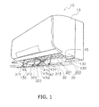
- FIG. 1 is a perspective view of an air conditioning indoor unit 10 according to an embodiment of the present invention when the air conditioning indoor unit 10 is in operation.
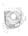
- FIG. 2 is a cross-sectional view of the air conditioning indoor unit 10 according to FIG. 1 when the air conditioning indoor unit is not in operation.
- the air conditioning indoor unit 10 is a wall-mounted indoor unit, equipped with an indoor heat exchanger 11, an indoor fan 12, a main body casing 13, a bottom frame 17, a filter 25, and a controller 40.
- a three-dimensional space is formed by a front surface grill 13 a, a front surface panel 13b, and a rear surface plate 13c, and the indoor heat exchanger 11, the indoor fan 12, the bottom frame 17, the filter 25, and the controller 40 are accommodated in this three-dimensional space.
- the front surface panel 13b covers the front surface of the front surface grill 13a, the top end is pivotably supported on the front surface grill 13a, and the front surface panel can be hinged.
- the main body casing 13 is mounted to a wall via an attachment plate (not shown).
- the indoor heat exchanger 11 and the indoor fan 12 are attached to the bottom frame 17.
- the indoor heat exchanger 11 conducts heat exchange with the air passing through. Seen from the side, the indoor heat exchanger 11 has an inverse V shape bent downward at both ends, below which the indoor fan 12 is positioned.
- a blow-out port 15 is provided to the bottom surface of the main body casing 13.
- a vertical airflow direction adjustment vane 30 for guiding the air blown out from the blow-out port 15 is attached to the blow-out port 15 in a pivotable manner.
- the vertical airflow direction adjustment vane 30, which is driven by a motor (not shown), is capable not only of varying the blow-out direction of the air, but also of opening and closing the blow-out port 15.
- the blow-out port 15 is joined to the interior of the main body casing 13 by a blow-out flow channel 18, and the blow-out flow channel 18 is formed from the blow-out port 15 along the bottom frame 17.
- An upright vane 20 is disposed in the blow-out flow channel 18 as shown in FIG. 2 .
- the upright vane 20 can direct the blown-out air at least toward either the front surface or the side surfaces of the main body casing 13.
- the filter 25 is disposed between the indoor heat exchanger 11 and the front surface grill 13a of the main body casing 13. The filter 25 removes dust in the air flowing into the indoor heat exchanger 11.
- An intake port 22 is provided to the front top part of the front surface grill 13a. Indoor air near the intake port 22 is drawn into the indoor fan 12 through the intake port 22, the filter 25 and the indoor heat exchanger 11 by the operation of the indoor fan 12, and is blown through the blow-out flow channel 18 and out of the blow-out port 15 by the indoor fan 12.
- the controller 40 which is accommodated in the front portion of the main body casing 13, performs actions such as controlling the rotating speed of the indoor fan 12 and adjusting the opening degree of the blow-out port 15.
- the opening degree of the blow-out port 15 is adjusted via the vertical airflow direction adjustment vane 30 and an auxiliary vane 130.
- the vertical airflow direction adjustment vane 30 which is a plate-shaped member having a substantially rectangular shape as shown in FIGS. 1 and 2 , waits in a position covering the opening of the blow-out port 15 (referred to as the closed position hereinafter) when the air conditioning indoor unit 10 stops operating.
- a first surface 30a which can be seen from the exterior in the closed position of the vertical airflow direction adjustment vane 30, supports part of the bottom surface of the main body casing 13.
- a first front linking part 311, a second front linking part 312, and a third front linking part 313 are provided to a second surface 30b, which is on the back of the first surface 30a of the vertical airflow direction adjustment vane 30, and a third front linking part 313 (see FIG. 1 ).
- the first front linking part 311, the second front linking part 312, and the third front linking part 313 are disposed on the front end side of the second surface 30b in the closed position of the vertical airflow direction adjustment vane 30, at substantially equal intervals along the longitudinal direction of the second surface 30b.
- first rear linking part 321 and a second rear linking part 322 are provided on the second surface 30b of the vertical airflow direction adjustment vane 30.
- the first rear linking part 321 and the second rear linking part 322 are disposed on the rear end side of the second surface 30b in the closed position of the vertical airflow direction adjustment vane 30, in the longitudinal middle of the second surface 30b.
- arcuate rack members 46 are linked respectively to the first front linking part 311, the second front linking part 312, and the third front linking part 313.
- the racks 46a of rack and pinion mechanisms are formed in the convex surfaces of the rack members 46, and the rack members 46 are oriented with the racks 46a facing at an upward incline of the blow-out port 15.
- foldable link members 47 are linked respectively to the first rear linking part 321 and the second rear linking part 322 as shown in FIG. 1 .
- the link members 47 are configured by two pairs of rod-shaped members rotatably coupled to each other at the ends.
- the two rod-shaped link members 47 above a joint 47c are referred to as top links 47a and the members below the joint are referred to as bottom links 47b.
- FIG. 3 is a side view of the bottom of the air conditioning indoor unit 10 when the vertical airflow direction adjustment vane 30 has left the blow-out port 15 open.
- a first stepper motor 51 is installed inside the main body casing 13, and a pinion gear 51 a is attached to a rotating shaft of the first stepper motor 51.
- the pinion gear 51 a meshes with the racks 46a and the first stepper motor 51 rotates the pinion gear 51 a clockwise as seen from the front of FIG. 3 , whereby the rack members 46 move to the front of the blow-out port 15 and the front part of the vertical airflow direction adjustment vane 30 approaches the front of the blow-out port 15. This is referred to as the first action of the first stepper motor 51.
- a second stepper motor 52 is installed inside the main body casing 13, and a drive gear 52a is attached to a rotating shaft of the second stepper motor 52.
- a driven gear 48 is provided to the ends of the top links 47a of the link members 47, and the second stepper motor 52 rotates the driven gear 48 clockwise as seen from the front of FIG. 3 via the drive gear 52a, thereby enlarging the center angle formed by the top links 47a and the bottom links 47b about the joint 47c and causing the rear part of the vertical airflow direction adjustment vane 30 to approach the front of the blow-out port 15. This is referred to as the first action of the second stepper motor 52.
- the vertical airflow direction adjustment vane 30 approaches the front of the blow-out port 15 due to the first action of the first stepper motor 51 and the first action of the second stepper motor 52 being performed simultaneously or continuously.
- the vertical airflow direction adjustment vane 30 retracts into the blow-out port 15 due to the second action of the first stepper motor 51 and the second action of the second stepper motor 52 being performed simultaneously or continuously.
- the orientation of the vertical airflow direction adjustment vane 30 shown in FIG. 3 is a vertical blowing orientation used during a dehumidifying operation or the like, but the vane can take various other orientations through a combination of the first and second actions of the first stepper motor 51 and the first and second actions of the second stepper motor 52. Typical orientations are described below with reference to the drawings.
- FIG. 4 is a side view of the vertical airflow direction adjustment vane 30 in a downward blowing orientation used during a heating operation.
- FIG. 5 is a side view of the vertical airflow direction adjustment vane 30 in an upward blowing orientation used during a heating operation.
- the downward blowing orientation of the vertical airflow direction adjustment vane 30 during the heating operation is achieved due to the first stepper motor 51 rotating the pinion gear 51a by an angle A1 clockwise as seen from the front of FIG. 3 , and the second stepper motor 52 rotating the driven gear 48 by an angle B1 clockwise as seen from the front of FIG. 3 , using the closed position as a reference.
- the upward blowing orientation of the vertical airflow direction adjustment vane 30 during the heating operation is achieved due to the first stepper motor 51 rotating the pinion gear 51a by an angle A1 clockwise as seen from the front of FIG. 3 , and the second stepper motor 52 rotating the driven gear 48 by an angle B2 clockwise as seen from the front of FIG. 3 , using the closed position as a reference.
- the angle B2 is greater than or equal to the angle B1.
- two auxiliary vanes 130 having pivot shafts parallel to the lengthwise edge of the blow-out port 15 are provided in the rear part of the blow-out port 15.
- the two auxiliary vanes 130 are adjacent to each other along the longitudinal direction of the blow-out port 15.
- Two middle support parts 131 each supporting an end of a pivot shaft of an auxiliary vane 130, are provided to the main body casing 13 in positions facing the middle part of the blow-out port 15.
- side support parts 132 are provided for supporting the other ends of pivot shafts of auxiliary vanes 130.
- the auxiliary vanes 130 When the vertical airflow direction adjustment vane 30 is in the closed position as shown in FIG. 2 , the auxiliary vanes 130 are stored above the vertical airflow direction adjustment vane 30 in an orientation substantially parallel to the vertical airflow direction adjustment vane 30, and cannot be seen from the exterior. At this time, the auxiliary vanes 130 draw near so as to overlap the second surface 30b of the vertical airflow direction adjustment vane 30, the auxiliary vanes 130 therefore occupy only a small space of the blow-out flow channel 18, and there is minimal interference with other members (e.g. the upright vane 20) disposed in the periphery of the blow-out port 15 and in the blow-out flow channel 18.
- other members e.g. the upright vane 20
- the distal ends of the auxiliary vanes 130 pivot so as to face the rear end of the vertical airflow direction adjustment vane 30.
- air blown out from the blow-out port 15 strikes the second surface 30b of the vertical airflow direction adjustment vane 30 to be divided into air moving at an upward incline and air moving at a downward incline.
- the auxiliary vanes 130 are interposed in the space between the blow-out port 15 and the rear end of the vertical airflow direction adjustment vane 30, the auxiliary vanes 130 block air that would otherwise pass through this space and leak out to the rear. As a result, fouling of the wall surface by the blown out air is prevented.
- the auxiliary vanes 130 pivot so as to be substantially parallel with the vertical airflow direction adjustment vane 30.
- the auxiliary vanes 130 not only block blown out air that would otherwise leak out to the rear, but also lead this blown out air in a direction parallel with the vertical airflow direction adjustment vane 30.
- the upright vane 20 has a plurality of vane pieces 201, and a linking rod 203 for linking the plurality of vane pieces 201, as shown in FIG. 1 .
- the upright vane 20 is disposed in the blow-out flow channel 18, nearer to the indoor fan 12 than the second surface 30b of the vertical airflow direction adjustment vane 30 in the closed position, as shown in FIG. 2 .
- the vane pieces 201 are plate pieces that gradually increase in surface area from the indoor fan 12 side of the blow-out flow channel 18 toward the blow-out port 15 side.
- Slit holes 201a where the linking rod 203 is inserted are formed in the blow-out port 15 sides, and support parts 201b supported inside the main body casing 13 are formed in the ends on the indoor fan 12 sides.
- In each vane piece 201 are formed two slits 201c extending from the middle toward the support part 201b.
- the plurality of vane pieces 201 swing to the left and right about a state of being perpendicular to the longitudinal direction of the main body casing 13, due to the linking rod 203 moving horizontally back and forth along the longitudinal direction of the blow-out port 15.
- the linking rod 203 is moved horizontally back and forth by a motor (not shown).
- the vane pieces 201 can be switched between a first state (see FIG. 1 ) of blowing the air from the blow-out port 15 out to the front surface of the main body casing 13, and a second state of blowing the air out to the side surfaces of the main body casing 13.
- FIG. 6 is a perspective view of the vane pieces 201 in the second state and the periphery thereof.
- each of the vane pieces 201 bends with the portion between the two slits 201c as a cantilever, the support part 201 b being the fixed end. Therefore, the distal ends of the vane pieces 201 face the side surface of the main body casing 13, which is the second state.
- a longer blow-out direction length of the vane pieces 201 of the upright vane 20 corresponds to an increasing capability of the air blown out laterally being directed in the desired direction. Therefore, in the present embodiment, the vane pieces 201 in the first state are set to a size at which there will be interference with the vertical airflow direction adjustment vane 30 in the closed state.
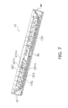
- FIG. 7 is a partial cross-sectional view of the air conditioning indoor unit 10 along line A-A in FIG. 1 .
- the vane pieces 201 to the right of the middle of the upright vane 20 adopt an orientation in which the distal ends face the right side surface RF
- the vane pieces 201 to the left of the middle of the upright vane 20 adopt an orientation in which the distal ends face the left side surface LF.
- the controller 40 stores the auxiliary vanes 130 and returns the vertical airflow direction adjustment vane 30 to the closed position after having switched to the second state of blowing the air from the blow-out port 15 out to the side surfaces of the main body casing 13.
- the vane pieces 201 remain in the first state and the distal ends of the vane pieces 201 and the vertical airflow direction adjustment vane 30 interfere with each other. Furthermore, there is also interference with the auxiliary vanes 130 because the auxiliary vanes 130 are stored above the vertical airflow direction adjustment vane 30. Such interference can not only cause creaking sounds, but can also cause the vane pieces 201 to deform.
- the vane pieces 201 are in the second state as shown in FIG. 7 when the controller 40 stops the operation of the air conditioning indoor unit 10, therefore preventing interference between the auxiliary vanes 130 stored in the blow-out port 15 and the vertical airflow direction adjustment vane 30 returned to the closed position. Even if there is interference, the extent of the interference is small, and the occurrence of creaking sounds and/or deformation of the vane pieces 201 are therefore prevented.
- the linking rod 203 of the upright vane 20 is driven by a stepper motor, and when the vertical airflow direction adjustment vane 30 is in the closed position, the second state of the vane pieces 201 is the original position of the upright vane 20.
- the controller 40 must temporarily move the upright vane 20 to the original position and then return the upright vane 20 to the stored position that immediately preceded the previous stop, but because the upright vane 20 is already in the original position (the vane pieces 201 are in the second state) at the time of the stop, the time to the original position is omitted.
- the distal ends of half of the plurality of vane pieces 201 face the right side surface RF, and those of the other half face the left side surface LF, but the present invention is not limited to this arrangement, and the same effect is achieved even if the distal ends of all of the vane pieces 201 face either the right side surface RF or the left side surface LF.
- the upright vane 20 is disposed in the main body casing 13, and is capable of switching the state of air blown out from the blow-out port 15 to the first state and the second state.
- the first state is a state of blowing air out to the front surface of the main body casing 13
- the second state is a state of blowing air out to the side surfaces of the main body casing 13. Because the controller 40 stores the auxiliary vanes 130 and puts the vertical airflow direction adjustment vane 30 in the closed state after putting the upright vane 20 in the second state when operation has stopped, the vertical airflow direction adjustment vane 30 and the auxiliary vanes 130 do not interfere with the upright vane 20, or, even if there is interference, the extent thereof is small.
- the upright vane 20 can be made long in the blow-out direction, air blown out transversely can be directed in the desired direction, and it is possible to prevent plastic deformation of the upright vane caused by interference between the vertical airflow direction adjustment vane and the upright vane when operation has stopped.
- the second state of the upright vane 20 is the original position of the upright vane 20.
- the process of returning the upright vane 20 to the original position when operation restarts is omitted compared with a conventional air conditioning indoor unit in which the upright vane is returned to the original position with every operation restart.
- a conventional air conditioning indoor unit in which the upright vane is returned to the original position with every operation restart.
- the controller 40 stores the position of the upright vane 20 immediately preceding the stop of operation, and returns the upright vane to this position when operation is restarted.
- the time needed for the upright vane 20 to return to the position immediately preceding the previous stop is less than in conventional practice because the upright vane 20 is already in the original position when operation is started. Therefore, it is possible to reduce the unpleasant feeling for a user who would feel that there is a long time required from the start of operation for the air blowing action to take effect.
- the length of the upright vane along the air blow-out direction is greater than in conventional practice, and air can be efficiently blown out in the desired direction. Consequently, the present invention is useful as the type of air conditioning indoor unit in which the intake port automatically opens and closes.
Landscapes
- Engineering & Computer Science (AREA)
- Chemical & Material Sciences (AREA)
- Combustion & Propulsion (AREA)
- Mechanical Engineering (AREA)
- General Engineering & Computer Science (AREA)
- Air-Flow Control Members (AREA)
- Air Conditioning Control Device (AREA)
- Air Filters, Heat-Exchange Apparatuses, And Housings Of Air-Conditioning Units (AREA)
Abstract
Description
- The present invention relates to an air conditioning indoor unit.
- Air blown out from a blow-out port of an air conditioning indoor unit can be blown in different directions by a vertical airflow direction adjustment vane disposed in proximity to the blow-out port, and an upright vane disposed on the inner side of the blow-out port. In the indoor unit disclosed in Patent Document 1 (Japanese Laid-open Patent Application No.
2006-2984 - However, because the left and right airflow direction plates (the upright vane) disclosed in
Patent Document 1 are housed at some point within a blowout flow channel leading from an indoor fan to the blow-out port, the air passing through the blowout flow channel can be deviated to the left and right, but it is doubtful that air coming out of the blow-out port could move in the desired direction. - An object of the present invention is to provide an air conditioning indoor unit capable of efficiently blowing air out in the desired direction when blowing out air to the left and right.
- An air conditioning indoor unit according to a first aspect of the present invention is an air conditioning indoor unit capable of varying the direction at which air is blown from a blow-out port, comprising a casing, an upright vane, a vertical direction adjustment vane, and a controller. A blow-out port is formed in the casing. The upright vane is disposed in the casing and is capable of switching the state of air blown from the blow-out port to either a first state or a second state. The first state is a state of blowing the air out to the front surface of the casing. The second state is a state of blowing the air out to the side surfaces of the casing. The vertical airflow direction adjustment vane is in an open state of opening the blow-out port during operation and is in a closed state of closing the blow-out port when operation has stopped. The controller controls the actions of the upright vane and the vertical airflow direction adjustment vane. The upright vane is set to a size that interferes with the closed vertical airflow direction adjustment vane when in the first state. The controller puts the vertical airflow direction adjustment vane into the closed state after putting the upright vane into the second state when operation has stopped.
- In this air conditioning indoor unit, because the controller puts the vertical airflow direction adjustment vane into the closed state after putting the upright vane into the second state when operation has stopped, the upright vane and the vertical airflow direction adjustment vane do not interfere with each other, or, even if there is interference, the extent thereof is small. Therefore, the upright vane can be made long in the blow-out direction, air blown out transversely can therefore be directed in the desired direction, and it is possible to prevent plastic deformation of the upright vane caused by interference between the vertical airflow direction adjustment vane and the upright vane when operation has stopped.
- An air conditioning indoor unit according to a second aspect of the present invention is the air conditioning indoor unit according to the first aspect, wherein the second state of the upright vane is the original position of the upright vane when the vertical airflow direction adjustment vane is in the closed state.
- Conventional practice has been to return the upright vane to the original position with every operation restart, but with this air conditioning indoor unit, the return to the original point of the upright vane during an operation restart can be omitted by having the second state of the upright vane when the vertical airflow direction adjustment vane is in the closed state be the original position of the upright vane. As a result, it is possible to reduce the unpleasant feeling for a user who would feel that there is a long time required from the start of operation for the air blowing action to take effect.
- An air conditioning indoor unit according to a third aspect of the present invention is the air conditioning indoor unit according to the second aspect, wherein the controller stores the position of the upright vane immediately preceding the stop of operation and returns the upright vane to this position when operation is restarted.
- With this air conditioning indoor unit, returning the upright vane to the original position during an operation restart can be omitted, less time than in conventional practice is therefore needed to return the upright vane to the position at the time of the previous operation, and it is possible to proportionately reduce the unpleasant feeling for a user who would feel that there is a long time required from the start of operation for the air blowing action to take effect.
- An air conditioning indoor unit according to a fourth aspect of the present invention is the air conditioning indoor unit according to the third aspect, wherein the upright vane has a plurality of upright vane pieces aligned at intervals. When operation has stopped, the controller orients the left half of the plurality of upright vane pieces toward the left side surface of the casing and orients the right half toward the right side surface of the casing.
- With this air conditioning indoor unit, and particularly with the type of air conditioning indoor unit that can separate the blown out air into left and right independent currents, returning the upright vane to the original position during an operation restart can be omitted, less time than in conventional practice is therefore needed following the start of operation to return the upright vane to the position at the time of the previous operation, and it is possible to proportionately reduce the unpleasant feeling for a user who would feel that there is a long time required from the start of operation for the air blowing action to take effect.
- An air conditioning indoor unit according to a fifth aspect of the present invention is the air conditioning indoor unit according to the third aspect, wherein the upright vane has a plurality of upright vane pieces aligned at intervals. When operation has stopped, the controller orients all of the upright vane pieces to the right or left.
- With this air conditioning indoor unit, and particularly with the type of air conditioning indoor unit that directs the blown out air to the left or right, returning the upright vane to the original position during an operation restart can be omitted, less time than in conventional practice is therefore needed following the start of operation to return the upright vane to the position at the time of the previous operation, and it is possible to proportionately reduce the unpleasant feeling for a user who would feel that there is a long time required from the start of operation for the air blowing action to take effect.
- An air conditioning indoor unit according to a sixth aspect of the present invention is the air conditioning indoor unit according to the first aspect, further provided with auxiliary vanes. The auxiliary vanes reduce the gap formed between the blow-out port and the rear end of the vertical airflow direction adjustment vane when the airflow direction adjustment vane takes a nearly horizontal orientation during operation. The auxiliary vanes are stored in a position nearer to the upright vane than the vertical airflow direction adjustment vane in a closed state when operation has stopped. The upright vane is set to a size that interferes with the stored auxiliary vanes when in the first state. The controller puts the auxiliary vanes into the stored state after putting the upright vane into the second state when operation has stopped.
- In this air conditioning indoor unit, because the controller puts the auxiliary vanes into the stored state after putting the upright vane into the second state when operation has stopped, the upright vane and the auxiliary vanes do not interfere with each other, or, even if there is interference, the extent thereof is small. Therefore, the upright vane can be made long in the blow-out direction, air blown out transversely can therefore be directed in the desired direction, and it is possible to prevent plastic deformation of the upright vane caused by interference between the auxiliary vanes and the upright vane when operation has stopped.
- In the air conditioning indoor unit according to the first aspect of the present invention, the upright vane and the vertical airflow direction adjustment vane do not interfere with each other, or, even if there is interference, the extent thereof is small. Therefore, the upright vane can be made long in the blow-out direction, air blown out transversely can therefore be directed in the desired direction, and it is possible to prevent plastic deformation of the upright vane caused by interference between the vertical airflow direction adjustment vane and the upright vane when operation has stopped.
- In the air conditioning indoor unit according to any of the second through fifth aspects, because less time than in conventional practice is needed to return the upright vane to the position at the time of the previous operation, it is possible to proportionately reduce the unpleasant feeling for a user who would feel that there is a long time required from the start of operation for the air blowing action to take effect.
- In the air conditioning indoor unit according to the sixth aspect of the present invention, the upright vane and the auxiliary vanes do not interfere with each other, or, even if there is interference, the extent thereof is small. Therefore, the upright vane can be made long in the blow-out direction, air blown out transversely can be directed in the desired direction, and it is possible to prevent plastic deformation of the upright vane caused by interference between the auxiliary vanes and the upright vane when operation has stopped.
-
-
FIG. 1 is a perspective view of an air conditioning indoor unit according to an embodiment of the present invention when the air conditioning indoor unit is in operation. -
FIG. 2 is a cross-sectional view of the air conditioning indoor unit according toFIG. 1 when the air conditioning indoor unit is not in operation. -
FIG. 3 is a side view of the bottom of the air conditioning indoor unit when the vertical airflow direction adjustment vane has left the blow-out port open. -
FIG. 4 is a side view of the vertical airflow direction adjustment vane in a downward blowing orientation used during a heating operation. -
FIG. 5 is a side view of the vertical airflow direction adjustment vane in an upward blowing orientation used during a heating operation. -
FIG. 6 is a perspective view of the vane pieces in the second state and the periphery thereof. -
FIG. 7 is a partial cross-sectional view of the air conditioning indoor unit along line A-A inFIG. 1 . - Embodiments of the present invention are described below with reference to the drawings. The following embodiments are specific examples of the present invention, and these examples do not limit the technical scope of the present invention.
-
FIG. 1 is a perspective view of an air conditioningindoor unit 10 according to an embodiment of the present invention when the air conditioningindoor unit 10 is in operation.FIG. 2 is a cross-sectional view of the air conditioningindoor unit 10 according toFIG. 1 when the air conditioning indoor unit is not in operation. - In
FIGS. 1 and2 , the air conditioningindoor unit 10 is a wall-mounted indoor unit, equipped with anindoor heat exchanger 11, anindoor fan 12, amain body casing 13, abottom frame 17, afilter 25, and acontroller 40. - In the
main body casing 13, a three-dimensional space is formed by afront surface grill 13 a, afront surface panel 13b, and arear surface plate 13c, and theindoor heat exchanger 11, theindoor fan 12, thebottom frame 17, thefilter 25, and thecontroller 40 are accommodated in this three-dimensional space. Thefront surface panel 13b covers the front surface of thefront surface grill 13a, the top end is pivotably supported on thefront surface grill 13a, and the front surface panel can be hinged. Themain body casing 13 is mounted to a wall via an attachment plate (not shown). - The
indoor heat exchanger 11 and theindoor fan 12 are attached to thebottom frame 17. Theindoor heat exchanger 11 conducts heat exchange with the air passing through. Seen from the side, theindoor heat exchanger 11 has an inverse V shape bent downward at both ends, below which theindoor fan 12 is positioned. Theindoor fan 12, which is a cross flow fan, blows air taken in from the room back out into the room after the air has passed through theindoor heat exchanger 11. - A blow-out
port 15 is provided to the bottom surface of themain body casing 13. A vertical airflowdirection adjustment vane 30 for guiding the air blown out from the blow-outport 15 is attached to the blow-outport 15 in a pivotable manner. The vertical airflowdirection adjustment vane 30, which is driven by a motor (not shown), is capable not only of varying the blow-out direction of the air, but also of opening and closing the blow-outport 15. The blow-outport 15 is joined to the interior of the main body casing 13 by a blow-out flow channel 18, and the blow-out flow channel 18 is formed from the blow-outport 15 along thebottom frame 17. - An
upright vane 20 is disposed in the blow-out flow channel 18 as shown inFIG. 2 . Theupright vane 20 can direct the blown-out air at least toward either the front surface or the side surfaces of themain body casing 13. - The
filter 25 is disposed between theindoor heat exchanger 11 and thefront surface grill 13a of themain body casing 13. Thefilter 25 removes dust in the air flowing into theindoor heat exchanger 11. - An
intake port 22 is provided to the front top part of thefront surface grill 13a. Indoor air near theintake port 22 is drawn into theindoor fan 12 through theintake port 22, thefilter 25 and theindoor heat exchanger 11 by the operation of theindoor fan 12, and is blown through the blow-out flow channel 18 and out of the blow-outport 15 by theindoor fan 12. - The
controller 40, which is accommodated in the front portion of themain body casing 13, performs actions such as controlling the rotating speed of theindoor fan 12 and adjusting the opening degree of the blow-outport 15. The opening degree of the blow-outport 15 is adjusted via the vertical airflowdirection adjustment vane 30 and anauxiliary vane 130. - The vertical airflow
direction adjustment vane 30, which is a plate-shaped member having a substantially rectangular shape as shown inFIGS. 1 and2 , waits in a position covering the opening of the blow-out port 15 (referred to as the closed position hereinafter) when the air conditioningindoor unit 10 stops operating. Afirst surface 30a, which can be seen from the exterior in the closed position of the vertical airflowdirection adjustment vane 30, supports part of the bottom surface of themain body casing 13. - Provided to a
second surface 30b, which is on the back of thefirst surface 30a of the vertical airflowdirection adjustment vane 30, are a firstfront linking part 311, a secondfront linking part 312, and a third front linking part 313 (seeFIG. 1 ). The firstfront linking part 311, the secondfront linking part 312, and the thirdfront linking part 313 are disposed on the front end side of thesecond surface 30b in the closed position of the vertical airflowdirection adjustment vane 30, at substantially equal intervals along the longitudinal direction of thesecond surface 30b. - Furthermore, a first
rear linking part 321 and a secondrear linking part 322 are provided on thesecond surface 30b of the vertical airflowdirection adjustment vane 30. The firstrear linking part 321 and the secondrear linking part 322 are disposed on the rear end side of thesecond surface 30b in the closed position of the vertical airflowdirection adjustment vane 30, in the longitudinal middle of thesecond surface 30b. - The ends of
arcuate rack members 46 are linked respectively to the firstfront linking part 311, the secondfront linking part 312, and the thirdfront linking part 313. Theracks 46a of rack and pinion mechanisms are formed in the convex surfaces of therack members 46, and therack members 46 are oriented with theracks 46a facing at an upward incline of the blow-outport 15. - The ends of
foldable link members 47 are linked respectively to the firstrear linking part 321 and the secondrear linking part 322 as shown inFIG. 1 . Thelink members 47 are configured by two pairs of rod-shaped members rotatably coupled to each other at the ends. The two rod-shapedlink members 47 above a joint 47c are referred to astop links 47a and the members below the joint are referred to asbottom links 47b. -
FIG. 3 is a side view of the bottom of the air conditioningindoor unit 10 when the vertical airflowdirection adjustment vane 30 has left the blow-outport 15 open. InFIG. 3 , afirst stepper motor 51 is installed inside themain body casing 13, and apinion gear 51 a is attached to a rotating shaft of thefirst stepper motor 51. Thepinion gear 51 a meshes with theracks 46a and thefirst stepper motor 51 rotates thepinion gear 51 a clockwise as seen from the front ofFIG. 3 , whereby therack members 46 move to the front of the blow-outport 15 and the front part of the vertical airflowdirection adjustment vane 30 approaches the front of the blow-outport 15. This is referred to as the first action of thefirst stepper motor 51. - Conversely, the
rack members 46 are retracted into the back of the main body casing 13 by thefirst stepper motor 51 rotating thepinion gear 51a counterclockwise as seen from the front ofFIG. 3 . This is referred to as the second action of thefirst stepper motor 51. - Furthermore, a
second stepper motor 52 is installed inside themain body casing 13, and adrive gear 52a is attached to a rotating shaft of thesecond stepper motor 52. A drivengear 48 is provided to the ends of thetop links 47a of thelink members 47, and thesecond stepper motor 52 rotates the drivengear 48 clockwise as seen from the front ofFIG. 3 via thedrive gear 52a, thereby enlarging the center angle formed by thetop links 47a and thebottom links 47b about the joint 47c and causing the rear part of the vertical airflowdirection adjustment vane 30 to approach the front of the blow-outport 15. This is referred to as the first action of thesecond stepper motor 52. - Conversely, the center angle formed by the
top links 47a and thebottom links 47b about the joint 47c is reduced by thedrive gear 52a rotating the drivengear 48 counterclockwise as seen from the front ofFIG. 3 , and the rear part of the vertical airflowdirection adjustment vane 30 retracts into the blow-outport 15. This is referred to as the second action of thesecond stepper motor 52. - Therefore, the vertical airflow
direction adjustment vane 30 approaches the front of the blow-outport 15 due to the first action of thefirst stepper motor 51 and the first action of thesecond stepper motor 52 being performed simultaneously or continuously. The vertical airflowdirection adjustment vane 30 retracts into the blow-outport 15 due to the second action of thefirst stepper motor 51 and the second action of thesecond stepper motor 52 being performed simultaneously or continuously. - The orientation of the vertical airflow
direction adjustment vane 30 shown inFIG. 3 is a vertical blowing orientation used during a dehumidifying operation or the like, but the vane can take various other orientations through a combination of the first and second actions of thefirst stepper motor 51 and the first and second actions of thesecond stepper motor 52. Typical orientations are described below with reference to the drawings. -
FIG. 4 is a side view of the vertical airflowdirection adjustment vane 30 in a downward blowing orientation used during a heating operation.FIG. 5 is a side view of the vertical airflowdirection adjustment vane 30 in an upward blowing orientation used during a heating operation. InFIG. 4 , the downward blowing orientation of the vertical airflowdirection adjustment vane 30 during the heating operation is achieved due to thefirst stepper motor 51 rotating thepinion gear 51a by an angle A1 clockwise as seen from the front ofFIG. 3 , and thesecond stepper motor 52 rotating the drivengear 48 by an angle B1 clockwise as seen from the front ofFIG. 3 , using the closed position as a reference. - In
FIG. 5 , the upward blowing orientation of the vertical airflowdirection adjustment vane 30 during the heating operation is achieved due to thefirst stepper motor 51 rotating thepinion gear 51a by an angle A1 clockwise as seen from the front ofFIG. 3 , and thesecond stepper motor 52 rotating the drivengear 48 by an angle B2 clockwise as seen from the front ofFIG. 3 , using the closed position as a reference. The angle B2 is greater than or equal to the angle B1. - In
FIG. 1 , twoauxiliary vanes 130 having pivot shafts parallel to the lengthwise edge of the blow-outport 15 are provided in the rear part of the blow-outport 15. The twoauxiliary vanes 130 are adjacent to each other along the longitudinal direction of the blow-outport 15. - Two
middle support parts 131, each supporting an end of a pivot shaft of anauxiliary vane 130, are provided to the main body casing 13 in positions facing the middle part of the blow-outport 15. In the rear corners of the blow-outport 15 in themain body casing 13, side supportparts 132 are provided for supporting the other ends of pivot shafts ofauxiliary vanes 130. - When the vertical airflow
direction adjustment vane 30 is in the closed position as shown inFIG. 2 , theauxiliary vanes 130 are stored above the vertical airflowdirection adjustment vane 30 in an orientation substantially parallel to the vertical airflowdirection adjustment vane 30, and cannot be seen from the exterior. At this time, theauxiliary vanes 130 draw near so as to overlap thesecond surface 30b of the vertical airflowdirection adjustment vane 30, theauxiliary vanes 130 therefore occupy only a small space of the blow-out flow channel 18, and there is minimal interference with other members (e.g. the upright vane 20) disposed in the periphery of the blow-outport 15 and in the blow-out flow channel 18. - When the vertical airflow
direction adjustment vane 30 adopts a vertical blowing orientation during a dehumidifying operation or the like as shown inFIG. 3 , the distal ends of theauxiliary vanes 130 pivot so as to face the rear end of the vertical airflowdirection adjustment vane 30. When the vertical airflowdirection adjustment vane 30 adopts the vertical blowing orientation, air blown out from the blow-outport 15 strikes thesecond surface 30b of the vertical airflowdirection adjustment vane 30 to be divided into air moving at an upward incline and air moving at a downward incline. Because of the large space between the blow-outport 15 and the rear end of the vertical airflowdirection adjustment vane 30, some of the air moving at a downward incline flows to the rear wall of the blow-out port 15 (the wall to which the air conditioningindoor unit 10 is attached), causing the wall surface to become dirty. - In the present embodiment, because the
auxiliary vanes 130 are interposed in the space between the blow-outport 15 and the rear end of the vertical airflowdirection adjustment vane 30, theauxiliary vanes 130 block air that would otherwise pass through this space and leak out to the rear. As a result, fouling of the wall surface by the blown out air is prevented. - When the vertical airflow
direction adjustment vane 30 adopts the downward blowing orientation during the heating operation as shown inFIG. 4 , or when the vane adopts the upward blowing orientation during the heating operation as shown inFIG. 5 , theauxiliary vanes 130 pivot so as to be substantially parallel with the vertical airflowdirection adjustment vane 30. In this case, theauxiliary vanes 130 not only block blown out air that would otherwise leak out to the rear, but also lead this blown out air in a direction parallel with the vertical airflowdirection adjustment vane 30. - The
upright vane 20 has a plurality ofvane pieces 201, and a linkingrod 203 for linking the plurality ofvane pieces 201, as shown inFIG. 1 . Theupright vane 20 is disposed in the blow-out flow channel 18, nearer to theindoor fan 12 than thesecond surface 30b of the vertical airflowdirection adjustment vane 30 in the closed position, as shown inFIG. 2 . - The
vane pieces 201 are plate pieces that gradually increase in surface area from theindoor fan 12 side of the blow-out flow channel 18 toward the blow-outport 15 side.Slit holes 201a where the linkingrod 203 is inserted are formed in the blow-outport 15 sides, and supportparts 201b supported inside the main body casing 13 are formed in the ends on theindoor fan 12 sides. In eachvane piece 201 are formed twoslits 201c extending from the middle toward thesupport part 201b. - The plurality of
vane pieces 201 swing to the left and right about a state of being perpendicular to the longitudinal direction of themain body casing 13, due to the linkingrod 203 moving horizontally back and forth along the longitudinal direction of the blow-outport 15. The linkingrod 203 is moved horizontally back and forth by a motor (not shown). - Not only do the
vane pieces 201 swing, but they can also be stopped at any desired angle after swinging by stopping the motor. Therefore, thevane pieces 201 can be switched between a first state (seeFIG. 1 ) of blowing the air from the blow-outport 15 out to the front surface of themain body casing 13, and a second state of blowing the air out to the side surfaces of themain body casing 13. -
FIG. 6 is a perspective view of thevane pieces 201 in the second state and the periphery thereof. InFIG. 6 , when the linkingrod 203 has moved to the farthest limit along the longitudinal direction of the blow-outport 15, for example, each of thevane pieces 201 bends with the portion between the twoslits 201c as a cantilever, thesupport part 201 b being the fixed end. Therefore, the distal ends of thevane pieces 201 face the side surface of themain body casing 13, which is the second state. - A longer blow-out direction length of the
vane pieces 201 of theupright vane 20 corresponds to an increasing capability of the air blown out laterally being directed in the desired direction. Therefore, in the present embodiment, thevane pieces 201 in the first state are set to a size at which there will be interference with the vertical airflowdirection adjustment vane 30 in the closed state. -
FIG. 7 is a partial cross-sectional view of the air conditioningindoor unit 10 along line A-A inFIG. 1 . InFIG. 7 , thevane pieces 201 to the right of the middle of theupright vane 20 adopt an orientation in which the distal ends face the right side surface RF, and thevane pieces 201 to the left of the middle of theupright vane 20 adopt an orientation in which the distal ends face the left side surface LF. In other words, thecontroller 40 stores theauxiliary vanes 130 and returns the vertical airflowdirection adjustment vane 30 to the closed position after having switched to the second state of blowing the air from the blow-outport 15 out to the side surfaces of themain body casing 13. - When the
controller 40 has stopped the operation of the air conditioningindoor unit 10 and returned the vertical airflowdirection adjustment vane 30 to the closed position, thevane pieces 201 remain in the first state and the distal ends of thevane pieces 201 and the vertical airflowdirection adjustment vane 30 interfere with each other. Furthermore, there is also interference with theauxiliary vanes 130 because theauxiliary vanes 130 are stored above the vertical airflowdirection adjustment vane 30. Such interference can not only cause creaking sounds, but can also cause thevane pieces 201 to deform. - In view of this, in the present embodiment, the
vane pieces 201 are in the second state as shown inFIG. 7 when thecontroller 40 stops the operation of the air conditioningindoor unit 10, therefore preventing interference between theauxiliary vanes 130 stored in the blow-outport 15 and the vertical airflowdirection adjustment vane 30 returned to the closed position. Even if there is interference, the extent of the interference is small, and the occurrence of creaking sounds and/or deformation of thevane pieces 201 are therefore prevented. - In the air conditioning
indoor unit 10, the linkingrod 203 of theupright vane 20 is driven by a stepper motor, and when the vertical airflowdirection adjustment vane 30 is in the closed position, the second state of thevane pieces 201 is the original position of theupright vane 20. At the start of operation, thecontroller 40 must temporarily move theupright vane 20 to the original position and then return theupright vane 20 to the stored position that immediately preceded the previous stop, but because theupright vane 20 is already in the original position (thevane pieces 201 are in the second state) at the time of the stop, the time to the original position is omitted. Therefore, less time is needed than conventionally from the start of operation to return theupright vane 20 to the position that immediately preceded the previous stop, and it is possible to proportionately reduce the unpleasant feeling for a user who would feel that there is a long time required from the start of operation for the air blowing action to take effect. - In
FIG. 7 , the distal ends of half of the plurality ofvane pieces 201 face the right side surface RF, and those of the other half face the left side surface LF, but the present invention is not limited to this arrangement, and the same effect is achieved even if the distal ends of all of thevane pieces 201 face either the right side surface RF or the left side surface LF. - In the air conditioning
indoor unit 10, theupright vane 20 is disposed in themain body casing 13, and is capable of switching the state of air blown out from the blow-outport 15 to the first state and the second state. The first state is a state of blowing air out to the front surface of themain body casing 13, and the second state is a state of blowing air out to the side surfaces of themain body casing 13. Because thecontroller 40 stores theauxiliary vanes 130 and puts the vertical airflowdirection adjustment vane 30 in the closed state after putting theupright vane 20 in the second state when operation has stopped, the vertical airflowdirection adjustment vane 30 and theauxiliary vanes 130 do not interfere with theupright vane 20, or, even if there is interference, the extent thereof is small. Therefore, theupright vane 20 can be made long in the blow-out direction, air blown out transversely can be directed in the desired direction, and it is possible to prevent plastic deformation of the upright vane caused by interference between the vertical airflow direction adjustment vane and the upright vane when operation has stopped. - When the vertical airflow
direction adjustment vane 30 is in the closed state, the second state of theupright vane 20 is the original position of theupright vane 20. The process of returning theupright vane 20 to the original position when operation restarts is omitted compared with a conventional air conditioning indoor unit in which the upright vane is returned to the original position with every operation restart. As a result, it is possible to reduce the unpleasant feeling for a user who would feel that there is a long time required from the start of operation for the air blowing action to take effect. - In the air conditioning
indoor unit 10, thecontroller 40 stores the position of theupright vane 20 immediately preceding the stop of operation, and returns the upright vane to this position when operation is restarted. In this air conditioning indoor unit, the time needed for theupright vane 20 to return to the position immediately preceding the previous stop is less than in conventional practice because theupright vane 20 is already in the original position when operation is started. Therefore, it is possible to reduce the unpleasant feeling for a user who would feel that there is a long time required from the start of operation for the air blowing action to take effect. - As described above, according to the present invention, the length of the upright vane along the air blow-out direction is greater than in conventional practice, and air can be efficiently blown out in the desired direction. Consequently, the present invention is useful as the type of air conditioning indoor unit in which the intake port automatically opens and closes.
-
- 10
- Air conditioning indoor unit
- 13
- Main body casing
- 15
- Blow-out port
- 20
- Upright vane
- 30
- Vertical airflow direction adjustment vane
- 40
- Controller
- 130
- Auxiliary vane
- 201
- Vane piece
- <
Patent Document 1> Japanese Laid-open Patent Application No.2006-2984
Claims (6)
- An air conditioning indoor unit capable of varying the direction at which air is blown from a blow-out port (15), comprising:a casing (13) in which the blow-out port (15) is formed;an upright vane (20) disposed in the casing (13) and capable of switching the state of air blown from the blow-out port (15) to either a first state of blowing the air out to the front surface of the casing (13), or a second state of blowing the air out to a side surface of the casing (13);a vertical airflow direction adjustment vane (30) that is in an open state of opening the blow-out port (15) during operation and that is in a closed state of closing the blow-out port (15) when operation has stopped; anda controller (40) for controlling the actions of the upright vane (20) and the vertical airflow direction adjustment vane (30);the upright vane (20) being set to a size that interferes with the closed vertical airflow direction adjustment vane (30) when in the first state; andthe controller (40) putting the vertical airflow direction adjustment vane (30) into the closed state after putting the upright vane (20) into the second state when operation has stopped.
- The air conditioning indoor unit (10) according to claim 1, wherein
the second state of the upright vane (20) is the original position of the upright vane (20) when the vertical airflow direction adjustment vane (30) is in the closed state. - The air conditioning indoor unit (10) according to claim 2, wherein
the controller (40) stores the position of the upright vane (20) immediately preceding the stop of operation and returns the upright vane to said position when operation is restarted. - The air conditioning indoor unit (10) according to claim 3, wherein
the upright vane (20) has a plurality of upright vane pieces (201) aligned at intervals; and
when operation has stopped, the controller (40) orients the left half of the plurality of upright vane pieces (201) toward the left side surface of the casing (13) and orients the right half toward the right side surface of the casing (13). - The air conditioning indoor unit (10) according to claim 3, wherein
the upright vane (20) has a plurality of upright vane pieces (201) aligned at intervals; and
when operation has stopped, the controller (40) orients the upright vane pieces (201) to either the right or left. - The air conditioning indoor unit (10) according to claim 1, further comprising:an auxiliary vane (130) for reducing the gap formed between the blow-out port (15) and the rear end of the vertical airflow direction adjustment vane (30) taking a nearly horizontal orientation during operation;the auxiliary vane (130) being stored in a position nearer to the upright vane (20) than the vertical airflow direction adjustment vane (30) in a closed state when operation has stopped;the upright vane (20) being set to a size that interferes with the stored auxiliary vane (130) when in the first state; andthe controller (40) putting the auxiliary vane (130) into the stored state after putting the upright vane (20) into the second state when operation has stopped.
Applications Claiming Priority (2)
| Application Number | Priority Date | Filing Date | Title |
|---|---|---|---|
| JP2011189474A JP5267628B2 (en) | 2011-08-31 | 2011-08-31 | Air conditioning indoor unit |
| PCT/JP2012/062915 WO2013031306A1 (en) | 2011-08-31 | 2012-05-21 | Air-conditioning indoor unit |
Publications (3)
| Publication Number | Publication Date |
|---|---|
| EP2759780A1 true EP2759780A1 (en) | 2014-07-30 |
| EP2759780A4 EP2759780A4 (en) | 2015-10-28 |
| EP2759780B1 EP2759780B1 (en) | 2017-08-16 |
Family
ID=47755824
Family Applications (1)
| Application Number | Title | Priority Date | Filing Date |
|---|---|---|---|
| EP12828041.9A Not-in-force EP2759780B1 (en) | 2011-08-31 | 2012-05-21 | Air-conditioning indoor unit |
Country Status (5)
| Country | Link |
|---|---|
| EP (1) | EP2759780B1 (en) |
| JP (1) | JP5267628B2 (en) |
| CN (1) | CN103797310B (en) |
| ES (1) | ES2640946T3 (en) |
| WO (1) | WO2013031306A1 (en) |
Cited By (5)
| Publication number | Priority date | Publication date | Assignee | Title |
|---|---|---|---|---|
| EP3358266A4 (en) * | 2015-09-30 | 2018-10-31 | Daikin Industries, Ltd. | Air conditioner |
| EP3367014A4 (en) * | 2015-10-21 | 2019-05-08 | Gree Electric Appliances, Inc. of Zhuhai | PANEL DRIVE ASSEMBLY AND AIR CONDITIONER COMPRISING SAID ASSEMBLY |
| EP3441692A4 (en) * | 2016-05-31 | 2019-06-05 | Mitsubishi Heavy Industries Thermal Systems, Ltd. | Air conditioner |
| EP3745044A4 (en) * | 2018-01-25 | 2021-01-13 | Mitsubishi Electric Corporation | INDOOR UNIT FOR AIR CONDITIONER |
| EP3751212A4 (en) * | 2018-02-06 | 2021-08-25 | Hitachi-Johnson Controls Air Conditioning, Inc. | Indoor unit of air conditioner |
Families Citing this family (8)
| Publication number | Priority date | Publication date | Assignee | Title |
|---|---|---|---|---|
| JP5488574B2 (en) * | 2011-12-05 | 2014-05-14 | ダイキン工業株式会社 | Air conditioning indoor unit |
| JP6223953B2 (en) * | 2014-12-02 | 2017-11-01 | 三菱重工サーマルシステムズ株式会社 | Air conditioner |
| JP2016153717A (en) * | 2015-02-18 | 2016-08-25 | 三星電子株式会社Samsung Electronics Co.,Ltd. | Ceiling embedded type indoor machine and air conditioner using the same |
| WO2016133261A1 (en) * | 2015-02-18 | 2016-08-25 | 삼성전자주식회사 | Air conditioner |
| CN106288284B (en) * | 2016-10-08 | 2022-05-06 | 珠海格力电器股份有限公司 | Air guides and air conditioners |
| CN115046303B (en) * | 2017-01-04 | 2023-11-28 | 美的集团股份有限公司 | Rack and cabinet air conditioner |
| JP6668552B2 (en) * | 2017-12-05 | 2020-03-18 | 日立ジョンソンコントロールズ空調株式会社 | Air conditioner indoor unit |
| JP6792208B2 (en) * | 2018-03-30 | 2020-11-25 | 株式会社富士通ゼネラル | Ceiling embedded air conditioner |
Family Cites Families (16)
| Publication number | Priority date | Publication date | Assignee | Title |
|---|---|---|---|---|
| JPH0464044U (en) * | 1990-10-08 | 1992-06-01 | ||
| KR0168265B1 (en) * | 1996-09-03 | 1999-01-15 | 김광호 | Wind direction control apparatus and method for an airconditioner |
| TW342439B (en) * | 1996-09-12 | 1998-10-11 | Samsung Electronics Co Ltd | Discharge current control apparatus of air conditioner and method thereof |
| JPH10274433A (en) * | 1997-03-31 | 1998-10-13 | Fujitsu General Ltd | Air conditioner |
| JP2002340393A (en) * | 2001-05-18 | 2002-11-27 | Sanyo Electric Co Ltd | Indoor machine for air conditioner |
| JP3896968B2 (en) * | 2003-01-30 | 2007-03-22 | 株式会社富士通ゼネラル | Air conditioner indoor unit |
| JP2006002984A (en) | 2004-06-16 | 2006-01-05 | Fujitsu General Ltd | Air conditioner |
| JP4513548B2 (en) * | 2004-12-22 | 2010-07-28 | パナソニック株式会社 | Air conditioner indoor unit |
| JP4452229B2 (en) * | 2005-10-31 | 2010-04-21 | パナソニック株式会社 | Air conditioner |
| JP4720644B2 (en) * | 2006-06-26 | 2011-07-13 | パナソニック株式会社 | Air conditioner |
| JP4448876B2 (en) * | 2007-09-27 | 2010-04-14 | 日立アプライアンス株式会社 | Air conditioner |
| JP2010085070A (en) * | 2008-10-03 | 2010-04-15 | Hitachi Appliances Inc | Air conditioner |
| JP2010101513A (en) * | 2008-10-21 | 2010-05-06 | Hitachi Appliances Inc | Air conditioner |
| JP4844665B2 (en) * | 2009-10-05 | 2011-12-28 | ダイキン工業株式会社 | Air conditioner |
| JP4656257B1 (en) * | 2010-08-10 | 2011-03-23 | ダイキン工業株式会社 | Air conditioner |
| JP4945678B1 (en) * | 2010-11-30 | 2012-06-06 | パナソニック株式会社 | Air conditioner |
-
2011
- 2011-08-31 JP JP2011189474A patent/JP5267628B2/en not_active Expired - Fee Related
-
2012
- 2012-05-21 WO PCT/JP2012/062915 patent/WO2013031306A1/en not_active Ceased
- 2012-05-21 EP EP12828041.9A patent/EP2759780B1/en not_active Not-in-force
- 2012-05-21 CN CN201280041376.6A patent/CN103797310B/en not_active Expired - Fee Related
- 2012-05-21 ES ES12828041.9T patent/ES2640946T3/en active Active
Cited By (6)
| Publication number | Priority date | Publication date | Assignee | Title |
|---|---|---|---|---|
| EP3358266A4 (en) * | 2015-09-30 | 2018-10-31 | Daikin Industries, Ltd. | Air conditioner |
| EP3367014A4 (en) * | 2015-10-21 | 2019-05-08 | Gree Electric Appliances, Inc. of Zhuhai | PANEL DRIVE ASSEMBLY AND AIR CONDITIONER COMPRISING SAID ASSEMBLY |
| US11460218B2 (en) | 2015-10-21 | 2022-10-04 | Gree Electric Appliances, Inc. Of Zhuhai | Panel driving assembly and air conditioner having the same |
| EP3441692A4 (en) * | 2016-05-31 | 2019-06-05 | Mitsubishi Heavy Industries Thermal Systems, Ltd. | Air conditioner |
| EP3745044A4 (en) * | 2018-01-25 | 2021-01-13 | Mitsubishi Electric Corporation | INDOOR UNIT FOR AIR CONDITIONER |
| EP3751212A4 (en) * | 2018-02-06 | 2021-08-25 | Hitachi-Johnson Controls Air Conditioning, Inc. | Indoor unit of air conditioner |
Also Published As
| Publication number | Publication date |
|---|---|
| JP5267628B2 (en) | 2013-08-21 |
| JP2013050281A (en) | 2013-03-14 |
| CN103797310B (en) | 2015-04-15 |
| CN103797310A (en) | 2014-05-14 |
| ES2640946T3 (en) | 2017-11-07 |
| EP2759780A4 (en) | 2015-10-28 |
| EP2759780B1 (en) | 2017-08-16 |
| WO2013031306A1 (en) | 2013-03-07 |
Similar Documents
| Publication | Publication Date | Title |
|---|---|---|
| EP2759780B1 (en) | Air-conditioning indoor unit | |
| EP2208942A2 (en) | Air conditioner | |
| JP2015031452A (en) | Air conditioner | |
| CN101995078A (en) | Wind direction changing device of air conditioner | |
| JP2015166662A (en) | air conditioner | |
| JP5131408B2 (en) | Air conditioning indoor unit | |
| JP5375900B2 (en) | Air conditioning indoor unit | |
| JP2011202896A (en) | Air conditioner | |
| JP5348294B2 (en) | Air conditioning indoor unit | |
| JP5080210B2 (en) | Air conditioner | |
| JP2012220062A (en) | Air conditioning indoor unit | |
| EP2463600A1 (en) | Air conditioner indoor unit | |
| JP4656257B1 (en) | Air conditioner | |
| JP4720934B2 (en) | Air conditioner indoor unit | |
| JP2017227438A (en) | Air conditioner | |
| KR20090067535A (en) | HVAC equipment and control method | |
| JP6418865B2 (en) | Air conditioner | |
| KR20140046669A (en) | An air conditioner | |
| AU2016319452B8 (en) | Wall-Mounted Air Conditioning Indoor Unit | |
| JP5282713B2 (en) | Air conditioner | |
| JP6069866B2 (en) | Air conditioning indoor unit | |
| JP6814940B2 (en) | Floor-standing air conditioner | |
| JP2012042181A (en) | Indoor unit of air conditioner | |
| JP2018017418A (en) | Air conditioner | |
| CN101737919A (en) | Air conditioner |
Legal Events
| Date | Code | Title | Description |
|---|---|---|---|
| PUAI | Public reference made under article 153(3) epc to a published international application that has entered the european phase |
Free format text: ORIGINAL CODE: 0009012 |
|
| 17P | Request for examination filed |
Effective date: 20140319 |
|
| AK | Designated contracting states |
Kind code of ref document: A1 Designated state(s): AL AT BE BG CH CY CZ DE DK EE ES FI FR GB GR HR HU IE IS IT LI LT LU LV MC MK MT NL NO PL PT RO RS SE SI SK SM TR |
|
| DAX | Request for extension of the european patent (deleted) | ||
| RA4 | Supplementary search report drawn up and despatched (corrected) |
Effective date: 20150930 |
|
| RIC1 | Information provided on ipc code assigned before grant |
Ipc: F24F 11/02 20060101ALI20150924BHEP Ipc: F24F 13/15 20060101ALI20150924BHEP Ipc: F24F 13/14 20060101AFI20150924BHEP Ipc: F24F 13/20 20060101ALI20150924BHEP |
|
| GRAP | Despatch of communication of intention to grant a patent |
Free format text: ORIGINAL CODE: EPIDOSNIGR1 |
|
| STAA | Information on the status of an ep patent application or granted ep patent |
Free format text: STATUS: GRANT OF PATENT IS INTENDED |
|
| INTG | Intention to grant announced |
Effective date: 20170407 |
|
| GRAS | Grant fee paid |
Free format text: ORIGINAL CODE: EPIDOSNIGR3 |
|
| GRAA | (expected) grant |
Free format text: ORIGINAL CODE: 0009210 |
|
| STAA | Information on the status of an ep patent application or granted ep patent |
Free format text: STATUS: THE PATENT HAS BEEN GRANTED |
|
| AK | Designated contracting states |
Kind code of ref document: B1 Designated state(s): AL AT BE BG CH CY CZ DE DK EE ES FI FR GB GR HR HU IE IS IT LI LT LU LV MC MK MT NL NO PL PT RO RS SE SI SK SM TR |
|
| REG | Reference to a national code |
Ref country code: GB Ref legal event code: FG4D |
|
| REG | Reference to a national code |
Ref country code: CH Ref legal event code: EP |
|
| REG | Reference to a national code |
Ref country code: IE Ref legal event code: FG4D |
|
| REG | Reference to a national code |
Ref country code: AT Ref legal event code: REF Ref document number: 919448 Country of ref document: AT Kind code of ref document: T Effective date: 20170915 |
|
| REG | Reference to a national code |
Ref country code: DE Ref legal event code: R096 Ref document number: 602012036094 Country of ref document: DE |
|
| REG | Reference to a national code |
Ref country code: ES Ref legal event code: FG2A Ref document number: 2640946 Country of ref document: ES Kind code of ref document: T3 Effective date: 20171107 |
|
| REG | Reference to a national code |
Ref country code: NL Ref legal event code: MP Effective date: 20170816 |
|
| REG | Reference to a national code |
Ref country code: LT Ref legal event code: MG4D |
|
| REG | Reference to a national code |
Ref country code: AT Ref legal event code: MK05 Ref document number: 919448 Country of ref document: AT Kind code of ref document: T Effective date: 20170816 |
|
| PG25 | Lapsed in a contracting state [announced via postgrant information from national office to epo] |
Ref country code: LT Free format text: LAPSE BECAUSE OF FAILURE TO SUBMIT A TRANSLATION OF THE DESCRIPTION OR TO PAY THE FEE WITHIN THE PRESCRIBED TIME-LIMIT Effective date: 20170816 Ref country code: FI Free format text: LAPSE BECAUSE OF FAILURE TO SUBMIT A TRANSLATION OF THE DESCRIPTION OR TO PAY THE FEE WITHIN THE PRESCRIBED TIME-LIMIT Effective date: 20170816 Ref country code: NL Free format text: LAPSE BECAUSE OF FAILURE TO SUBMIT A TRANSLATION OF THE DESCRIPTION OR TO PAY THE FEE WITHIN THE PRESCRIBED TIME-LIMIT Effective date: 20170816 Ref country code: NO Free format text: LAPSE BECAUSE OF FAILURE TO SUBMIT A TRANSLATION OF THE DESCRIPTION OR TO PAY THE FEE WITHIN THE PRESCRIBED TIME-LIMIT Effective date: 20171116 Ref country code: AT Free format text: LAPSE BECAUSE OF FAILURE TO SUBMIT A TRANSLATION OF THE DESCRIPTION OR TO PAY THE FEE WITHIN THE PRESCRIBED TIME-LIMIT Effective date: 20170816 Ref country code: SE Free format text: LAPSE BECAUSE OF FAILURE TO SUBMIT A TRANSLATION OF THE DESCRIPTION OR TO PAY THE FEE WITHIN THE PRESCRIBED TIME-LIMIT Effective date: 20170816 |
|
| PG25 | Lapsed in a contracting state [announced via postgrant information from national office to epo] |
Ref country code: RS Free format text: LAPSE BECAUSE OF FAILURE TO SUBMIT A TRANSLATION OF THE DESCRIPTION OR TO PAY THE FEE WITHIN THE PRESCRIBED TIME-LIMIT Effective date: 20170816 Ref country code: BG Free format text: LAPSE BECAUSE OF FAILURE TO SUBMIT A TRANSLATION OF THE DESCRIPTION OR TO PAY THE FEE WITHIN THE PRESCRIBED TIME-LIMIT Effective date: 20171116 Ref country code: IS Free format text: LAPSE BECAUSE OF FAILURE TO SUBMIT A TRANSLATION OF THE DESCRIPTION OR TO PAY THE FEE WITHIN THE PRESCRIBED TIME-LIMIT Effective date: 20171216 Ref country code: PL Free format text: LAPSE BECAUSE OF FAILURE TO SUBMIT A TRANSLATION OF THE DESCRIPTION OR TO PAY THE FEE WITHIN THE PRESCRIBED TIME-LIMIT Effective date: 20170816 Ref country code: GR Free format text: LAPSE BECAUSE OF FAILURE TO SUBMIT A TRANSLATION OF THE DESCRIPTION OR TO PAY THE FEE WITHIN THE PRESCRIBED TIME-LIMIT Effective date: 20171117 Ref country code: LV Free format text: LAPSE BECAUSE OF FAILURE TO SUBMIT A TRANSLATION OF THE DESCRIPTION OR TO PAY THE FEE WITHIN THE PRESCRIBED TIME-LIMIT Effective date: 20170816 |
|
| PG25 | Lapsed in a contracting state [announced via postgrant information from national office to epo] |
Ref country code: CZ Free format text: LAPSE BECAUSE OF FAILURE TO SUBMIT A TRANSLATION OF THE DESCRIPTION OR TO PAY THE FEE WITHIN THE PRESCRIBED TIME-LIMIT Effective date: 20170816 Ref country code: DK Free format text: LAPSE BECAUSE OF FAILURE TO SUBMIT A TRANSLATION OF THE DESCRIPTION OR TO PAY THE FEE WITHIN THE PRESCRIBED TIME-LIMIT Effective date: 20170816 Ref country code: RO Free format text: LAPSE BECAUSE OF FAILURE TO SUBMIT A TRANSLATION OF THE DESCRIPTION OR TO PAY THE FEE WITHIN THE PRESCRIBED TIME-LIMIT Effective date: 20170816 |
|
| REG | Reference to a national code |
Ref country code: DE Ref legal event code: R097 Ref document number: 602012036094 Country of ref document: DE |
|
| REG | Reference to a national code |
Ref country code: FR Ref legal event code: PLFP Year of fee payment: 7 |
|
| PG25 | Lapsed in a contracting state [announced via postgrant information from national office to epo] |
Ref country code: SK Free format text: LAPSE BECAUSE OF FAILURE TO SUBMIT A TRANSLATION OF THE DESCRIPTION OR TO PAY THE FEE WITHIN THE PRESCRIBED TIME-LIMIT Effective date: 20170816 Ref country code: EE Free format text: LAPSE BECAUSE OF FAILURE TO SUBMIT A TRANSLATION OF THE DESCRIPTION OR TO PAY THE FEE WITHIN THE PRESCRIBED TIME-LIMIT Effective date: 20170816 Ref country code: SM Free format text: LAPSE BECAUSE OF FAILURE TO SUBMIT A TRANSLATION OF THE DESCRIPTION OR TO PAY THE FEE WITHIN THE PRESCRIBED TIME-LIMIT Effective date: 20170816 |
|
| PLBE | No opposition filed within time limit |
Free format text: ORIGINAL CODE: 0009261 |
|
| STAA | Information on the status of an ep patent application or granted ep patent |
Free format text: STATUS: NO OPPOSITION FILED WITHIN TIME LIMIT |
|
| 26N | No opposition filed |
Effective date: 20180517 |
|
| PGFP | Annual fee paid to national office [announced via postgrant information from national office to epo] |
Ref country code: ES Payment date: 20180601 Year of fee payment: 7 Ref country code: DE Payment date: 20180518 Year of fee payment: 7 |
|
| PG25 | Lapsed in a contracting state [announced via postgrant information from national office to epo] |
Ref country code: SI Free format text: LAPSE BECAUSE OF FAILURE TO SUBMIT A TRANSLATION OF THE DESCRIPTION OR TO PAY THE FEE WITHIN THE PRESCRIBED TIME-LIMIT Effective date: 20170816 |
|
| PGFP | Annual fee paid to national office [announced via postgrant information from national office to epo] |
Ref country code: TR Payment date: 20180508 Year of fee payment: 7 Ref country code: FR Payment date: 20180524 Year of fee payment: 7 Ref country code: IT Payment date: 20180516 Year of fee payment: 7 |
|
| REG | Reference to a national code |
Ref country code: CH Ref legal event code: PL |
|
| GBPC | Gb: european patent ceased through non-payment of renewal fee |
Effective date: 20180521 |
|
| REG | Reference to a national code |
Ref country code: BE Ref legal event code: MM Effective date: 20180531 |
|
| PG25 | Lapsed in a contracting state [announced via postgrant information from national office to epo] |
Ref country code: MC Free format text: LAPSE BECAUSE OF FAILURE TO SUBMIT A TRANSLATION OF THE DESCRIPTION OR TO PAY THE FEE WITHIN THE PRESCRIBED TIME-LIMIT Effective date: 20170816 |
|
| REG | Reference to a national code |
Ref country code: IE Ref legal event code: MM4A |
|
| PG25 | Lapsed in a contracting state [announced via postgrant information from national office to epo] |
Ref country code: CH Free format text: LAPSE BECAUSE OF NON-PAYMENT OF DUE FEES Effective date: 20180531 Ref country code: LI Free format text: LAPSE BECAUSE OF NON-PAYMENT OF DUE FEES Effective date: 20180531 |
|
| PG25 | Lapsed in a contracting state [announced via postgrant information from national office to epo] |
Ref country code: LU Free format text: LAPSE BECAUSE OF NON-PAYMENT OF DUE FEES Effective date: 20180521 |
|
| PG25 | Lapsed in a contracting state [announced via postgrant information from national office to epo] |
Ref country code: GB Free format text: LAPSE BECAUSE OF NON-PAYMENT OF DUE FEES Effective date: 20180521 Ref country code: IE Free format text: LAPSE BECAUSE OF NON-PAYMENT OF DUE FEES Effective date: 20180521 |
|
| PG25 | Lapsed in a contracting state [announced via postgrant information from national office to epo] |
Ref country code: BE Free format text: LAPSE BECAUSE OF NON-PAYMENT OF DUE FEES Effective date: 20180531 |
|
| REG | Reference to a national code |
Ref country code: DE Ref legal event code: R119 Ref document number: 602012036094 Country of ref document: DE |
|
| PG25 | Lapsed in a contracting state [announced via postgrant information from national office to epo] |
Ref country code: MT Free format text: LAPSE BECAUSE OF NON-PAYMENT OF DUE FEES Effective date: 20180521 |
|
| PG25 | Lapsed in a contracting state [announced via postgrant information from national office to epo] |
Ref country code: DE Free format text: LAPSE BECAUSE OF NON-PAYMENT OF DUE FEES Effective date: 20191203 Ref country code: IT Free format text: LAPSE BECAUSE OF NON-PAYMENT OF DUE FEES Effective date: 20190521 |
|
| PG25 | Lapsed in a contracting state [announced via postgrant information from national office to epo] |
Ref country code: PT Free format text: LAPSE BECAUSE OF FAILURE TO SUBMIT A TRANSLATION OF THE DESCRIPTION OR TO PAY THE FEE WITHIN THE PRESCRIBED TIME-LIMIT Effective date: 20170816 Ref country code: HU Free format text: LAPSE BECAUSE OF FAILURE TO SUBMIT A TRANSLATION OF THE DESCRIPTION OR TO PAY THE FEE WITHIN THE PRESCRIBED TIME-LIMIT; INVALID AB INITIO Effective date: 20120521 |
|
| PG25 | Lapsed in a contracting state [announced via postgrant information from national office to epo] |
Ref country code: CY Free format text: LAPSE BECAUSE OF FAILURE TO SUBMIT A TRANSLATION OF THE DESCRIPTION OR TO PAY THE FEE WITHIN THE PRESCRIBED TIME-LIMIT Effective date: 20170816 Ref country code: MK Free format text: LAPSE BECAUSE OF NON-PAYMENT OF DUE FEES Effective date: 20170816 Ref country code: FR Free format text: LAPSE BECAUSE OF NON-PAYMENT OF DUE FEES Effective date: 20190531 Ref country code: HR Free format text: LAPSE BECAUSE OF FAILURE TO SUBMIT A TRANSLATION OF THE DESCRIPTION OR TO PAY THE FEE WITHIN THE PRESCRIBED TIME-LIMIT Effective date: 20170816 |
|
| PG25 | Lapsed in a contracting state [announced via postgrant information from national office to epo] |
Ref country code: AL Free format text: LAPSE BECAUSE OF FAILURE TO SUBMIT A TRANSLATION OF THE DESCRIPTION OR TO PAY THE FEE WITHIN THE PRESCRIBED TIME-LIMIT Effective date: 20170816 |
|
| REG | Reference to a national code |
Ref country code: ES Ref legal event code: FD2A Effective date: 20200928 |
|
| PG25 | Lapsed in a contracting state [announced via postgrant information from national office to epo] |
Ref country code: ES Free format text: LAPSE BECAUSE OF NON-PAYMENT OF DUE FEES Effective date: 20190522 |
|
| PG25 | Lapsed in a contracting state [announced via postgrant information from national office to epo] |
Ref country code: TR Free format text: LAPSE BECAUSE OF NON-PAYMENT OF DUE FEES Effective date: 20190521 |