EP2759767A1 - A reactor chamber for a circulating fluidized bed boiler - Google Patents
A reactor chamber for a circulating fluidized bed boiler Download PDFInfo
- Publication number
- EP2759767A1 EP2759767A1 EP13152714.5A EP13152714A EP2759767A1 EP 2759767 A1 EP2759767 A1 EP 2759767A1 EP 13152714 A EP13152714 A EP 13152714A EP 2759767 A1 EP2759767 A1 EP 2759767A1
- Authority
- EP
- European Patent Office
- Prior art keywords
- reactor chamber
- grate
- inlet duct
- target zone
- extraction device
- Prior art date
- Legal status (The legal status is an assumption and is not a legal conclusion. Google has not performed a legal analysis and makes no representation as to the accuracy of the status listed.)
- Withdrawn
Links
Images


Classifications
-
- F—MECHANICAL ENGINEERING; LIGHTING; HEATING; WEAPONS; BLASTING
- F23—COMBUSTION APPARATUS; COMBUSTION PROCESSES
- F23C—METHODS OR APPARATUS FOR COMBUSTION USING FLUID FUEL OR SOLID FUEL SUSPENDED IN A CARRIER GAS OR AIR
- F23C10/00—Fluidised bed combustion apparatus
- F23C10/18—Details; Accessories
- F23C10/24—Devices for removal of material from the bed
-
- F—MECHANICAL ENGINEERING; LIGHTING; HEATING; WEAPONS; BLASTING
- F23—COMBUSTION APPARATUS; COMBUSTION PROCESSES
- F23C—METHODS OR APPARATUS FOR COMBUSTION USING FLUID FUEL OR SOLID FUEL SUSPENDED IN A CARRIER GAS OR AIR
- F23C10/00—Fluidised bed combustion apparatus
- F23C10/02—Fluidised bed combustion apparatus with means specially adapted for achieving or promoting a circulating movement of particles within the bed or for a recirculation of particles entrained from the bed
- F23C10/04—Fluidised bed combustion apparatus with means specially adapted for achieving or promoting a circulating movement of particles within the bed or for a recirculation of particles entrained from the bed the particles being circulated to a section, e.g. a heat-exchange section or a return duct, at least partially shielded from the combustion zone, before being reintroduced into the combustion zone
- F23C10/08—Fluidised bed combustion apparatus with means specially adapted for achieving or promoting a circulating movement of particles within the bed or for a recirculation of particles entrained from the bed the particles being circulated to a section, e.g. a heat-exchange section or a return duct, at least partially shielded from the combustion zone, before being reintroduced into the combustion zone characterised by the arrangement of separation apparatus, e.g. cyclones, for separating particles from the flue gases
- F23C10/10—Fluidised bed combustion apparatus with means specially adapted for achieving or promoting a circulating movement of particles within the bed or for a recirculation of particles entrained from the bed the particles being circulated to a section, e.g. a heat-exchange section or a return duct, at least partially shielded from the combustion zone, before being reintroduced into the combustion zone characterised by the arrangement of separation apparatus, e.g. cyclones, for separating particles from the flue gases the separation apparatus being located outside the combustion chamber
-
- F—MECHANICAL ENGINEERING; LIGHTING; HEATING; WEAPONS; BLASTING
- F27—FURNACES; KILNS; OVENS; RETORTS
- F27B—FURNACES, KILNS, OVENS OR RETORTS IN GENERAL; OPEN SINTERING OR LIKE APPARATUS
- F27B15/00—Fluidised-bed furnaces; Other furnaces using or treating finely-divided materials in dispersion
- F27B15/02—Details, accessories or equipment specially adapted for furnaces of these types
Definitions
- the present invention relates to a circulating fluidized bed boiler reactor chamber comprising a circulating fluidized bed grate for combustion of a fuel in the reactor chamber under fluidized conditions, and a material inlet duct for transporting fuel into the reactor chamber and further to the grate for being combusted.
- the present invention further relates to a method of removing non-combustible objects from a circulating fluidized bed boiler reactor chamber.
- a CFB boiler comprises a circulating fluidized bed grate on which the fuel is fluidized by the combustion air, optionally together with a bed material, which may be sand, and is combusted in this fluidized state.
- the fuel may, for example, be biomass, household waste, coal, or peat.
- the fuel supplied to the CFB grate may comprise impurities, such as pieces of rock, steel pieces, etc, that are not combustible. Such impurities are sometimes referred to as tramp material.
- the grate comprises removal devices for removing tramp material from the grate.
- US 6,263,837 discloses a CFB grate in which a plurality of pockets are arranged in the grate to allow discharge of tramp material.
- An object of the present invention is to provide a circulating fluidized bed boiler reactor chamber which is more efficient than the devices of the prior art with regard to removing non-combustible objects.
- a circulating fluidized bed boiler reactor chamber comprising a circulating fluidized bed grate for combustion of a fuel in the reactor chamber under fluidized conditions, and a material inlet duct for transporting fuel into the reactor chamber and further to the grate for being combusted, wherein the grate is provided with at least a first particle extraction device for discharge of non-combustible objects from the grate, wherein the at least a first particle extraction device is arranged within a first target zone located on the grate, the position of the first target zone being based on at least one trajectory path of a non-combustible object entering the reactor chamber via the material inlet duct.
- An advantage of this reactor chamber is that the first particle extraction device is arranged in that position, namely within the first target zone, where it is most likely that non-combustible objects will land on the grate. Thereby the first particle extraction device will collect the largest possible amount of non-combustible objects. Furthermore, there will be little need for further extraction devices since most if not all of the non-combustible objects will be captured by the first particle extraction device. This reduces the investment cost of the reactor chamber and makes combustion more efficient, since only a small percentage of the area of the grate is occupied by the extraction device, above which there is limited, if any, fluidisation.
- the first extraction device in this specific first target zone in an intelligent manner based on a trajectory path, in contrast to distributing a plurality of pockets evenly over the entire area of the grate as is done in the prior art, the investment cost is reduced, and the combustion efficiency is increased.
- the material inlet duct is inclined an angle ⁇ to the horizontal plane, and a lower end of the material inlet duct enters, via an opening in a reactor chamber wall, the reactor chamber at a height HL above the grate, wherein the first target zone starts in a start position SP1 which is located a horizontal distance L1 from the opening in the reactor chamber inlet wall, the horizontal distance L1 being in the range of: HL tan ⁇ * 0.8 ⁇ L ⁇ 1 ⁇ HL tan ⁇ * 1.2
- An advantage of this embodiment is that the first target zone, within which the first particle extraction device is arranged, starts in a position where impact on the grate of non-combustible objects ejected from the inlet duct are expected to start.
- This start position SP1 may, within the above mentioned limits, coincide with an impact position on the grate of an object that follows a trajectory path following a lower end of the inlet duct and straight towards the surface of the grate.
- the material inlet duct may, according to one embodiment, be inclined an angle ⁇ to the horizontal plane, wherein the angle ⁇ is preferably 20-80°, more typically 30-70°, to obtain efficient circulation of solids, i.e., recirculated bed material and fuel, into the reactor chamber and further to the grate. If the angle ⁇ is less than 20° the risk of solids getting stuck inside the material inlet duct increases. If the angle ⁇ is more than 80°, the spreading of fuel over the grate may be less efficient.
- the material inlet duct is inclined an angle ⁇ to the horizontal plane, and the material inlet duct has a height of DI, wherein the first target zone has a horizontal length L2 being in the range of: DI 2 * sin ⁇ * 0.8 ⁇ L ⁇ 2 ⁇ DI 2 * sin ⁇ * 1.2
- the first target zone obtains a suitable length for capturing most non-combustible objects, regardless of whether these objects are located at the bottom or at the top of the physical material stream being supplied from the material inlet duct into the reactor chamber.
- the height DI could, for example, be a diameter in the case of a circular inlet duct, and could be a duct height in the case of a square or rectangular inlet duct.
- the material inlet duct is inclined an angle ⁇ to the horizontal plane, has a height of DI, and a lower end of the inlet duct enters, via an opening in a reactor chamber wall, the reactor chamber at a height HL above the grate, wherein the first target zone ends in an end position EP1 which is located a horizontal distance L1+L2 from the opening in the reactor chamber inlet wall, the horizontal distance L1+L2 being in the range of: HL tan ⁇ * 0.8 + DI 2 * sin ⁇ * 0.8 ⁇ L ⁇ 1 + L ⁇ 2 ⁇ HL tan ⁇ * 1.2 + DI 2 * sin ⁇ * 1.2
- An advantage of this embodiment is that the first target zone, within which the first particle extraction device is arranged, ends in a position where impact on the grate of non-combustible objects ejected from the inlet duct are expected to stop.
- This end position EP1 may, within the above mentioned limits, coincide with an impact position on the grate of an object that follows a trajectory path following a centre line of the inlet duct and straight towards the surface of the grate.
- an inlet opening of the first particle extraction device has a horizontal length of EL1 in the range of: 50 ⁇ mm ⁇ EL ⁇ 1 ⁇ 400 ⁇ mm
- a horizontal length EL1 of less than 50 mm the risk is increased that some non-combustible objects are too large and cannot be captured, resulting in unwanted accumulation of non-combustible objects on the grate.
- a horizontal length EL1 of more than 400 mm the fluidisation over the grate is substantially reduced, which may result in less efficient combustion, and/or a risk that some bed material and/or fuel is inadvertently captured in the first particle extraction device.
- two or more particle extraction devices are arranged within the first target zone at different horizontal distances from the opening in the reactor chamber inlet wall.
- the grate comprises at least one intermediate row of fluidizing gas nozzles arranged between two separate particle extraction devices.
- an inlet opening of the first particle extraction device has a width EW1 which is based on the minimum width of the material flow WMIN of the inlet duct and the maximum width of the material flow WMAX of the inlet duct and which is in the range of: WMIN ⁇ EW ⁇ 1 ⁇ 2 * WMAX
- the width EW1 of the first particle extraction device is, according to one embodiment, at least as wide as a minimum width of a stream of material entering the reactor chamber via the inlet duct, and not wider than two times the maximum width of a stream of material entering the reactor chamber via the inlet duct. Thereby, the particle extraction device has a good chance of capturing non-combustible material supplied from the inlet duct.
- a width EW1 of more than two times the maximum width of the stream of material entering the reactor chamber via the inlet duct is often less efficient, since it reduces the fluidization over the grate without resulting in a substantial increase in the capture of non-combustible material.
- a width EW1 of an inlet opening of the first particle extraction device is larger than a length EL1 of the inlet opening, meaning that the inlet opening has a rectangular shape and extends perpendicular to the longitudinal direction of the inlet duct.
- the grate is provided with at least a second particle extraction device for discharge of non-combustible objects from the grate, wherein the at least a second particle extraction device is arranged within a second target zone located on the grate in a position which is separate from the position of the first target zone, the position of the second target zone being based on a different trajectory path of a non-combustible object entering the reactor chamber via the material inlet duct than the trajectory path on which the position of the first target zone is based.
- An advantage of this embodiment is that also non-combustible objects that do not follow the first-mentioned trajectory path may be captured and removed.
- non-combustible objects examples include objects that are quite heavy and drop down relatively quickly, and non-combustible material that enters the inlet duct when there is pile of non-combustible material accumulated inside the material inlet duct, adjacent to the outlet of the inlet duct.
- an inlet opening of the second particle extraction device has a horizontal length of EL2 in the range of: 50 ⁇ mm ⁇ EL ⁇ 2 ⁇ 400 ⁇ mm
- a length EL2 of less than 50 mm may result in non-combustible objects not being able to enter into the second particle extraction device, while a length EL2 of more than 400 mm may result in reduced fluidization efficiency.
- the length EL2 is at least 80 mm, more preferably at least 100 mm, to capture also large non-combustible objects.
- the second particle extraction device has a width EW2 which is preferably in the same range as described hereinbefore with regard to the width EW1 of the first particle extraction device.
- a width EW2 of an inlet opening of the second particle extraction device is larger than a length EL2 of the inlet opening, meaning that the inlet opening has a rectangular shape and extends perpendicular to the longitudinal direction of the inlet duct.
- the second particle extraction device will have a function similar to that of a moat or fence capturing non-combustible objects.
- the material inlet duct is inclined an angle ⁇ to the horizontal plane, and a lower end of the inlet duct enters, via an opening in a reactor chamber wall, the reactor chamber at a height HL above the grate, wherein the second target zone starts in a start position SP2 which is located a horizontal distance L3 from the opening in the reactor chamber inlet wall, the horizontal distance L3 being in the range of: 0 ⁇ L ⁇ 3 ⁇ HL tan ⁇ * 0.4
- An advantage of this embodiment is that the second target zone starts rather close to the reactor chamber inlet wall, which means that also very heavy objects that fall down on the grate almost immediately after the entering the reactor chamber may be captured in the second particle extraction device.
- the material inlet duct is inclined an angle ⁇ to the horizontal plane, and a lower end of the inlet duct enters, via an opening in a reactor chamber wall, the reactor chamber at a height HL above the grate, wherein the second target zone has a horizontal length L4 being in the range of: HL tan ⁇ * 0.1 ⁇ L ⁇ 4 ⁇ HL tan ⁇ * 0.5
- An advantage of this embodiment is that the second target zone obtains a suitable length for capturing also such non-combustible objects that do not fall down on the grate immediately after entering the reactor chamber, but that move a horizontal distance before impacting the grate.
- the material inlet duct is inclined an angle ⁇ to the horizontal plane, and a lower end of the inlet duct enters, via an opening in a reactor chamber inlet wall, the reactor chamber at a height HL above the grate, wherein the second target zone ends in an end position EP2 which is located a horizontal distance L3+L4 from the opening in the reactor chamber inlet wall, the horizontal distance L3+L4 being in the range of: HL tan ⁇ * 0.1 ⁇ L ⁇ 3 + L ⁇ 4 ⁇ HL tan ⁇ * 0.8
- An advantage of this embodiment is that the second target zone, within which the second particle extraction device is arranged, ends in a position where impact on the grate of heavy non-combustible objects and/or non-combustible objects hindered by material accumulated inside the material supply duct is expected to stop.
- a horizontal distance between the first target zone and the second target zone is at least 300 mm.
- the grate provides a reduced flow of fluidizing gas at the first extraction device and/or at the second extraction device compared to the flow of fluidizing gas at the rest of grate.
- the grate could be arranged without gas nozzles located vertically above the respective extraction device, and/or the grate could be provided for supplying less fluidizing gas to some of the gas nozzles located adjacent to the respective extraction device, compared to the amount of gas supplied to the rest of the gas nozzles of the grate. This will reduce the fluidization of non-combustible objects above the extraction device and further improve the capture of non-combustible objects in the extraction device.
- the grate comprises a barrier row of fluidizing gas nozzles arranged downstream, as seen in the flow direction of the fuel supplied from the material inlet duct, of the first particle extraction device to act as a barrier to non-combustible objects and to direct bouncing objects into the first particle extraction device.
- a barrier row of fluidizing gas nozzles may be arranged also at one or both of the sides of the first particle extraction device. According to a further embodiment a barrier row of fluidizing gas nozzles may be arranged also upstream of the particle extraction device.
- the grate comprises a barrier row of fluidizing gas nozzles arranged downstream, as seen in the flow direction of the fuel supplied from the material inlet duct, of the second particle extraction device to act as a barrier to non-combustible objects and to direct bouncing objects into the second particle extraction device.
- This object is achieved by means of a method of removing non-combustible objects from a circulating fluidized bed boiler reactor chamber comprising a circulating fluidized bed grate for combustion of a fuel in the reactor chamber under fluidized conditions, and a material inlet duct for transporting fuel into the reactor chamber and further to the grate for being combusted, the method comprising arranging at least a first particle extraction device for discharge of non-combustible objects from the grate within a first target zone located on the grate, the position of the first target zone being based on at least one trajectory path of a non-combustible object entering the reactor chamber via the material inlet duct, and capturing non-combustible objects by means of the first particle extraction device.
- An advantage of this method is that by arranging the first particle extraction device in that location where the non-combustible objects can be expected to impact the grate results in a very efficient removal of non-combustible objects.
- the method further comprises combusting biofuel in the reactor chamber.
- the present method provides, due to the efficient removal of non-combustible objects, particular advantages for combustion of biofuel since biofuels tend to comprise a comparably large amount of non-combustible objects, such as pieces of rock, nails, etc, that would rather quickly result in a large accumulation on the grate, and a need to stop operation for maintenance, unless the non-combustible objects are properly removed from the grate.
- Fig. 1 is a schematic representation of a circulating fluidized bed (CFB) boiler 1.
- the CFB boiler 1 comprises as its main parts a reactor chamber 2, a particle separator 4, and a seal pot 6.
- a wind box 8 is arranged for supplying a gas to a circulating fluidized bed grate 10 of the reactor chamber 2.
- An oxygen containing gas which may typically be ambient air, but which could also be, for example, oxygen gas, a mixture of oxygen gas and air, and/or a mixture of oxygen gas and recirculated combustion gas, is supplied to the windbox 8 via a gas duct 12.
- the circulating fluidized bed grate 10 comprises fluidizing gas nozzles 14, shown schematically in Fig. 1 , that distribute the oxygen containing gas over the surface of the grate 10 and causes a fluidization of the fuel and of the inert bed material, such as sand, if present.
- the oxygen containing gas supplied via gas duct 12 will, hence, serve as both the oxidant that oxidizes the fuel and as the fluidisation medium.
- the oxygen containing gas oxidizes the fuel inside the reactor chamber 2, and a mixture of combustion gas and bed material is transported from the reactor chamber 2 to the particle separator 4 via a discharge duct 16.
- the combustion gas typically comprises, as its main components, nitrogen, carbon dioxide, oxygen and water vapour, and also other gaseous and particulate components that are present in relatively small concentrations.
- the particle separator 4 which may, for example, have the form of one or many cyclones, the solid material, including bed material and any uncombusted portions of the fuel are separated from the combustion gas.
- the combustion gas is removed from the particle separator 4 via a gas discharge duct 18.
- the combustion gas removed via duct 18 may be exposed to further gas cleaning treatment, for example further removal of particulate material, prior to being released to the atmosphere, or being taken care of in another manner, for example being taken care of in a carbon dioxide cleaning and compression plant for sequestration of carbon dioxide.
- the solid particle material i.e., the bed material and the uncombusted portion of the fuel, separated in the particle separator 4 is removed via a particle discharge duct 20 and is forwarded to the seal pot 6.
- the seal pot 6 functions as a lock preventing combustion gas from the reactor chamber 2 from passing backwards into the particle separator 4.
- the solid material is then transported, via particle transport duct 22, from the seal pot 6.
- fuel is supplied, via a fuel supply duct 26, to the solid material transported from the seal pot 6 via duct 22.
- the fuel may, for example, be a biofuel, such as wood chips, hay, agricultural rest products, etc.
- the fuel may also be of other types, including household or industrial waste, peat, coal, or any other fuel that is suitable for combustion in the CFB boiler 1.
- An inclined material inlet duct 28 of the reactor chamber 2 is arranged for transporting the mixture of bed material and fuel into the reactor chamber 2 and further to the circulating fluidized bed grate 10.
- the fuel may comprise various impurities that are non-combustible. Some of these non-combustible impurities are non-combustible objects that are too heavy to be fluidized, which means they will not form part of the fluidized bed material. Examples of such impurities include pieces of rock, nails, excavator teeth etc.
- the circulating fluidized bed grate 10 is provided with at least one particle extraction device for removing such non-combustible objects, sometimes called tramp material, from the grate 10 to avoid accumulation of non-combustible objects on the grate 10.
- the grate 10 is provided with a first particle extraction device 30 and a second particle extraction device 32 which will be described in more detail hereinafter.
- Each particle extraction device 30, 32 is provided with a lock 34 controlling the discharge of collected non-combustible material to a transporting device 36 for transporting the collected non-combustible material away for disposal.
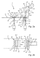
- Fig. 2a is a schematic drawing and illustrates the circulating fluidized bed grate 10 and the inlet duct 28 as seen from the side thereof, i.e. as seen in the same perspective as in Fig. 1 , but in an enlarged scale.
- the inlet duct 28 enters the reactor chamber 2 via an opening 38 formed in a reactor chamber inlet wall 40.
- the inlet duct 28 is inclined an angle ⁇ to the horizontal plane.
- the angle ⁇ between the inlet duct 28 and the horizontal plane is typically 20-80°, more typically 30-70°.
- the inlet duct 28 may have any suitable cross-section, including circular, oval, square, rectangular, etc.
- the inlet duct 28 has a circular cross-section, with an inner diameter DI and a centre line Cl.
- a lower end 42 of the inlet duct 28 enters, via the opening 38 in the reactor chamber inlet wall 40, the reactor chamber 2 at a height HL above the grate 10.
- the grate 10 is provided with a first target zone 44, within which the first particle extraction device 30 is arranged, and a second target zone 46, within which the second particle extraction device 32 is arranged.
- Each target zone 44, 46 is an imaginary horizontal area on the grate 10 which determines the location of one or more extraction devices 30, 32 and which has a position and extension adapted for efficient capture of non-combustible objects based on at least one trajectory path of a non-combustible object entering the reactor chamber 2 via the material inlet duct 28.
- the first target zone 44 starts in a start position SP1, which is a located a horizontal distance L1 from the opening 38 in the reactor chamber inlet wall 40, and ends in an end position EP1, which is located a horizontal distance L2 from the start position SP1.
- the first target zone 44 has a horizontal length L2.
- the first target zone 44 coincides at least partly with an area on the grate 10 onto which the material inlet duct 28 "shoots" material that is to be supplied to the reactor chamber 2.
- the distance L1 may be varied to some extent.
- the distance L1 should preferably be in the range: HL tan ⁇ * 0.8 ⁇ L ⁇ 1 ⁇ HL tan ⁇ * 1.2
- the length L2 may be varied to some extent.
- the length L2 should preferably be in the range: DI 2 * sin ⁇ * 0.8 ⁇ L ⁇ 2 ⁇ DI 2 * sin ⁇ * 1.2
- the end position EP1 is located a horizontal distance of L1 plus L2 from the reactor chamber inlet wall 40.
- a trajectory path TP1 illustrates how a non-combustible object in the form of a piece of tramp material, for example a nail, is introduced in the reactor chamber 2 by the material inlet duct 28, moves towards the first target zone 44, enters an inlet opening 48 of first particle extraction device 30 and is captured, and thereafter disposed of, as described hereinbefore with reference to Fig. 1 .
- a first barrier row 50 of fluidizing gas nozzles 14 are arranged downstream, as seen in the direction of the horizontal component of the trajectory path TP1, of the inlet opening 48 of the first particle extraction device 30.
- the barrier row 50 of nozzles 14 acts as a barrier to pieces of tramp material, and directs bouncing pieces of tramp material into the first particle extraction device 30.
- the flow of fluidizing gas is reduced above the first particle extraction device 30, compared to the rest of the grate 10, since there are no fluidizing gas nozzles vertically above the extraction device 30.
- the reduced flow of fluidizing gas above the extraction device 30 reduces the lifting forces on pieces of tramp material, and increases the chance of capturing pieces of tramp material in the first particle extraction device 30.
- the gas nozzles 14 located adjacent to the extraction device 30 could be provided with a reduced gas flow, compared to the other gas nozzles of the grate 10, to further reduce the lifting force in the vicinity of the extraction device 30 for further improved capture of pieces of tramp material.
- the second target zone 46 starts in a start position SP2 which is a located a horizontal distance L3 from the reactor chamber inlet wall 40, and ends in an end position EP2.
- the second target zone 46 has a length L4.
- the end position EP2 is located a horizontal distance L4 from the start position SP2, and is located a horizontal distance of L3+L4 from the reactor chamber inlet wall 40.
- the second target zone 46 is located in a drop-out zone of the material inlet duct 28, where heavier pieces of material may drop-out of the inlet duct 28, following a different shooting trajectory path than non-combustible objects captured at the first target zone 44.
- the start position SP2 is, in accordance with one embodiment, located adjacent to the reactor chamber inlet wall 40, which means that the distance L3 is equal to 0.
- the distance L3 may be varied to some extent.
- the distance L3 should preferably be in the range: 0 ⁇ L ⁇ 3 ⁇ HL tan ⁇ * 0.4
- the length L4 of the second target zone 46 is, in accordance with one embodiment, calculated according to the following equation, which is based on an estimated drop-out trajectory path ST3 based on the lower end 42 of the inlet duct 28: L ⁇ 4 ⁇ HL tan ⁇ * 0.25
- the length L4 may be varied to some extent.
- the length L4 should preferably be in the range: HL tan ⁇ * 0.1 ⁇ L ⁇ 4 ⁇ HL tan ⁇ * 0.5
- a trajectory path TP2 illustrates how a relatively heavy piece of tramp material, for example a piece of rock, is introduced in the reactor chamber 2 by the inlet duct 28, drops down towards the second target zone 46, enters an inlet opening 52 of second particle extraction device 32 and is captured, and thereafter disposed of, as described hereinbefore with reference to Fig. 1 .
- bed material may inadvertently accumulate inside the material inlet duct 28, adjacent to the outlet 38, to form a pile of material.
- the flow of fuel through the material inlet duct 28 may be at least temporarily hindered by such pile of material, which may result in non-combustible objects following trajectory path TP2 rather than trajectory path TP1 in such a situation.
- a second barrier row 54 of fluidizing gas nozzles 14 are arranged downstream, as seen in the direction of the horizontal component of the trajectory path TP2, of the second particle extraction device 32 to direct bouncing pieces of tramp material into the inlet opening 52 of second particle extraction device 32.
- the flow of fluidizing gas is reduced above the second particle extraction device 32, compared to the rest of the grate 10, since there are no fluidizing gas nozzles vertically above the extraction device 32.
- the gas nozzles 14 located adjacent to the extraction device 32 could be provided with a reduced gas flow, compared to the other gas nozzles of the grate 10, to further reduce the lifting force in the vicinity of the extraction device 32. Similar to what has been described hereinbefore with regard to the first extraction device 30, the reduced flow of fluidizing gas above the extraction device 32 increases the chance of capturing pieces of tramp material.
- a horizontal distance between the first target zone 44 and the second target zone 46 i.e., the distance between SP1 and EP2, is at least 300 mm.
- Fig. 2b illustrates the grate 10 and the material inlet duct 28 as seen from above.
- the inlet opening 48 of the first particle extraction device 30 is arranged within the first target zone 44 and has a width EW1 and a horizontal length EL1.
- the width EW1 is typically larger than the length EL1, meaning that the inlet opening 48 has a rectangular shape and extends perpendicular to the longitudinal direction of the inlet duct 28.
- the width EW1 may be related to the diameter DI of the inlet duct 28.
- the inlet opening 52 of the second particle extraction device 32 is arranged within the second target zone 46 and has a width EW2 and a horizontal length EL2.
- the width EW2 is typically larger than the length EL2, meaning that the inlet opening 52 has a rectangular shape and extends perpendicular to the longitudinal direction of the inlet duct 28.
- the inlet openings 48, 52 will have a function resembling that of a moat or fence arranged in the intended path of non-combustible objects and preventing them from accumulating on the grate 10.
- each of the lengths EL1, EL2 may be arranged to allow capture of relatively large non-combustible objects.
- each of the lengths EL1, EL2 fulfils the following criterion: 50 ⁇ mm ⁇ EL ⁇ 1 , EL ⁇ 2 ⁇ 400 ⁇ mm
- each of the lengths EL1, EL2 fulfils the following criterion: 80 ⁇ mm ⁇ EL ⁇ 1 , EL ⁇ 2 ⁇ 300 ⁇ mm
- the respective widths EW1 and EW2 may be designed based on the diameter of the inlet duct 28, based on principles described hereinafter with reference to Fig. 2c .
- Fig. 2c illustrates the inlet duct 28 as seen in cross-section.
- the maximum solid flow width MAW corresponds to the situation when the entire inner diameter DI of the inlet duct 28 is full with material.
- a minimum solid flow width MIW corresponds to the situation when the amount of material does not extend up to more than 1/6 of DI, i.e., DI/6, thereby defining for the sector filled with material in such a situation an angle ⁇ .
- the material supplied to the reactor chamber 2 via the inlet duct 28 can be expected to spread in the horizontal direction somewhat beyond the width of the inlet duct 28, such width being for a circular inlet duct 28 equal to the diameter DI.
- the widths EW1 and EW2 can be established: EW ⁇ 1 ⁇ EW ⁇ 2 ⁇ 2 * DI
- a preferable upper and lower range of the width EW1 of the opening 48 of the first particle extraction device 30 and a preferable upper and lower range of the width EW2 of the opening 52 of the second particle extraction device 32 can be calculated.
- width EW1, EW2 For an inlet duct having another shape than circular a similar calculation of suitable width EW1, EW2 could be performed.
- EW1, EW2 For an inlet duct having another shape than circular a similar calculation of suitable width EW1, EW2 could be performed.
- the material flow would always have the width WS, regardless of the load, and a suitable range for the widths EW1, EW2 could be calculated as: WS ⁇ EW ⁇ 1 , EW ⁇ 2 ⁇ 2 * WS
- the width EW1, EW2 of the particle extraction device 30, 32 is preferably 1 to 2 times the width of the material flow entering the reactor chamber 2.
- the minimum width of the material flow could be called WMIN, corresponding to MIW in the circular case and WS in the rectangular case
- WMAX maximum width of the material flow
- the preferable width EW1, EW2 of the respective particle extraction device 30, 32 can be calculated as: WMIN ⁇ EW ⁇ 1 , EW ⁇ 2 ⁇ 2 * WMAX
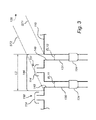
- Fig. 3 illustrates a grate 110 according to an alternative embodiment.
- This grate 110 has a first target zone 144, the position of which may be established based on shooting trajectory path ST1 and ST2 in accordance with principles similar to those described hereinbefore with regard to the first target zone 44 with reference to Fig. 2a .
- the target zone 144 has a horizontal length L2 which is substantially larger than the preferable length of an opening of a particle extraction device.
- a rear first particle extraction device 130 and a front first particle extraction device 131 are arranged within the first target zone 144 arranged a rear first particle extraction device 130 and a front first particle extraction device 131, each of which is provided with a lock 134 and is arranged for removal of non-combustible objects, such as tramp material, from the grate 110 in accordance with principles similar to those described hereinbefore with reference to Fig. 1 .
- the rear first particle extraction device 130 is arranged in the rear part of the first target zone 144, as seen with respect to the position of the inclined material inlet duct 128, not shown in Fig. 3
- the front first particle extraction device 131 is arranged in the front part of the first target zone 144.
- Each of the extraction devices 130, 131 has a respective inlet opening 148, 149 with a length EL11, EL12 which preferably fulfils the requirements of eq. 3.1 or 3.2 given hereinbefore for the lengths EL1 and EL2 of the extraction devices 30, 32.
- the lengths EL11 and EL12 may be the same or different.
- a first barrier row 150 of fluidizing gas nozzles 114 are arranged downstream, as seen in the direction of the horizontal component of the trajectory path, of the rear first particle extraction device 130.
- the barrier row 150 of nozzles 114 acts as a barrier to pieces of tramp material, and directs bouncing pieces of tramp material into the inlet opening 148 of the rear first particle extraction device 130.
- At least one intermediate row 151 of fluidizing gas nozzles 114 is arranged between the rear and front first particle extraction devices 130, 131. This intermediate row 151 of fluidizing gas nozzles 114 has two purposes. Firstly, the intermediate row 151 of nozzles 114 provides for fluidisation within the first target zone 144.
- the intermediate row 151 of nozzles 114 provides the function of acting as a barrier to pieces of tramp material, and directs bouncing pieces of tramp material into the inlet opening 149 of the front first particle extraction device 131.
- first particle extraction devices 130, 131 could be arranged in series within the target zone 144, with at least one intermediate row 151 of fluidizing gas nozzles 114 arranged there between.
- first target zone 144 could be provided with 3, 4, 5 or even more particle extraction devices arranged in series, and with intermediate rows of fluidizing gas nozzles arranged there between.
- intermediate row of fluidizing gas nozzles need not be a single row of nozzles, but could be several rows of nozzles and/or nozzles arranged in another pattern.
- the second target zone 46 illustrated in Figs. 2a and 2b could also be provided with 2, 3 or even more particle extraction devices arranged in series within the second target zone, and with one or more intermediate rows of fluidizing gas nozzles arranged there between, in accordance with the principles described with reference to Fig. 3 with respect to the first target zone 144.
- the reactor chamber 2 is provided with one material inlet duct 28. It will be appreciated that it is also possible to provide the reactor chamber 2 with two or more parallel material inlet ducts that may either be arranged adjacent to each other or at a distance from each other. In the latter case, specific first and second target zones are preferably arranged for each one of such parallel material inlet ducts.
- barrier row 50, 54 of fluidizing gas nozzles 14 may be arranged downstream of the respective first and second particle extraction device 30, 32. It will be appreciated that barrier rows of fluidizing gas nozzles may also be arranged at the sides of the respective first and second particle extraction device 30, 32, and/or upstream of the respective first and second particle extraction device 30, 32 to hinder non-combustible objects from bouncing away from the respective inlet opening 48, 52 of the extraction devices 30, 32. Hence, one or more barrier rows may be utilized as a shielding of the extraction device to further improve the capture of non-combustible objects.
- a circulating fluidized bed boiler reactor chamber (2) comprises a circulating fluidized bed grate (10) for combustion of a fuel in the reactor chamber (2) under fluidized conditions, and a material inlet duct (28) for transporting fuel into the reactor chamber (2) and further to the grate (10).
- the grate (10) is provided with at least a first particle extraction device (30) for discharge of non-combustible objects from the grate (10).
- the at least a first particle extraction device (30) is arranged within a first target zone (44) located on the grate (10).
- the position of the first target zone (44) is based on at least one trajectory path (ST1, ST2) of a non-combustible object entering the reactor chamber (2) via the material inlet duct (28).
Landscapes
- Engineering & Computer Science (AREA)
- Chemical & Material Sciences (AREA)
- Mechanical Engineering (AREA)
- General Engineering & Computer Science (AREA)
- Combustion & Propulsion (AREA)
- Dispersion Chemistry (AREA)
- Fluidized-Bed Combustion And Resonant Combustion (AREA)
Abstract
Description
- The present invention relates to a circulating fluidized bed boiler reactor chamber comprising a circulating fluidized bed grate for combustion of a fuel in the reactor chamber under fluidized conditions, and a material inlet duct for transporting fuel into the reactor chamber and further to the grate for being combusted.
- The present invention further relates to a method of removing non-combustible objects from a circulating fluidized bed boiler reactor chamber.
- In the combustion of a fuel a circulating fluidized bed (CFB) boiler may be used. A CFB boiler comprises a circulating fluidized bed grate on which the fuel is fluidized by the combustion air, optionally together with a bed material, which may be sand, and is combusted in this fluidized state. The fuel may, for example, be biomass, household waste, coal, or peat. The fuel supplied to the CFB grate may comprise impurities, such as pieces of rock, steel pieces, etc, that are not combustible. Such impurities are sometimes referred to as tramp material. To avoid accumulation of tramp material in the CFB grate the grate comprises removal devices for removing tramp material from the grate.
US 6,263,837 discloses a CFB grate in which a plurality of pockets are arranged in the grate to allow discharge of tramp material. - An object of the present invention is to provide a circulating fluidized bed boiler reactor chamber which is more efficient than the devices of the prior art with regard to removing non-combustible objects.
- This object is achieved by a circulating fluidized bed boiler reactor chamber comprising a circulating fluidized bed grate for combustion of a fuel in the reactor chamber under fluidized conditions, and a material inlet duct for transporting fuel into the reactor chamber and further to the grate for being combusted, wherein the grate is provided with at least a first particle extraction device for discharge of non-combustible objects from the grate, wherein the at least a first particle extraction device is arranged within a first target zone located on the grate, the position of the first target zone being based on at least one trajectory path of a non-combustible object entering the reactor chamber via the material inlet duct.
- An advantage of this reactor chamber is that the first particle extraction device is arranged in that position, namely within the first target zone, where it is most likely that non-combustible objects will land on the grate. Thereby the first particle extraction device will collect the largest possible amount of non-combustible objects. Furthermore, there will be little need for further extraction devices since most if not all of the non-combustible objects will be captured by the first particle extraction device. This reduces the investment cost of the reactor chamber and makes combustion more efficient, since only a small percentage of the area of the grate is occupied by the extraction device, above which there is limited, if any, fluidisation. Thus, by placing the first extraction device in this specific first target zone in an intelligent manner based on a trajectory path, in contrast to distributing a plurality of pockets evenly over the entire area of the grate as is done in the prior art, the investment cost is reduced, and the combustion efficiency is increased.
- According to one embodiment the material inlet duct is inclined an angle β to the horizontal plane, and a lower end of the material inlet duct enters, via an opening in a reactor chamber wall, the reactor chamber at a height HL above the grate, wherein the first target zone starts in a start position SP1 which is located a horizontal distance L1 from the opening in the reactor chamber inlet wall, the horizontal distance L1 being in the range of:

- An advantage of this embodiment is that the first target zone, within which the first particle extraction device is arranged, starts in a position where impact on the grate of non-combustible objects ejected from the inlet duct are expected to start. This start position SP1 may, within the above mentioned limits, coincide with an impact position on the grate of an object that follows a trajectory path following a lower end of the inlet duct and straight towards the surface of the grate.
- The material inlet duct may, according to one embodiment, be inclined an angle β to the horizontal plane, wherein the angle β is preferably 20-80°, more typically 30-70°, to obtain efficient circulation of solids, i.e., recirculated bed material and fuel, into the reactor chamber and further to the grate. If the angle β is less than 20° the risk of solids getting stuck inside the material inlet duct increases. If the angle β is more than 80°, the spreading of fuel over the grate may be less efficient.
- According to one embodiment the material inlet duct is inclined an angle β to the horizontal plane, and the material inlet duct has a height of DI, wherein the first target zone has a horizontal length L2 being in the range of:

- An advantage of this embodiment is that the first target zone obtains a suitable length for capturing most non-combustible objects, regardless of whether these objects are located at the bottom or at the top of the physical material stream being supplied from the material inlet duct into the reactor chamber. The height DI could, for example, be a diameter in the case of a circular inlet duct, and could be a duct height in the case of a square or rectangular inlet duct.
- According to one embodiment the material inlet duct is inclined an angle β to the horizontal plane, has a height of DI, and a lower end of the inlet duct enters, via an opening in a reactor chamber wall, the reactor chamber at a height HL above the grate, wherein the first target zone ends in an end position EP1 which is located a horizontal distance L1+L2 from the opening in the reactor chamber inlet wall, the horizontal distance L1+L2 being in the range of:

- An advantage of this embodiment is that the first target zone, within which the first particle extraction device is arranged, ends in a position where impact on the grate of non-combustible objects ejected from the inlet duct are expected to stop. This end position EP1 may, within the above mentioned limits, coincide with an impact position on the grate of an object that follows a trajectory path following a centre line of the inlet duct and straight towards the surface of the grate.
- According to one embodiment an inlet opening of the first particle extraction device has a horizontal length of EL1 in the range of:

- With a horizontal length EL1 of less than 50 mm the risk is increased that some non-combustible objects are too large and cannot be captured, resulting in unwanted accumulation of non-combustible objects on the grate. With a horizontal length EL1 of more than 400 mm the fluidisation over the grate is substantially reduced, which may result in less efficient combustion, and/or a risk that some bed material and/or fuel is inadvertently captured in the first particle extraction device.
- According to one embodiment two or more particle extraction devices are arranged within the first target zone at different horizontal distances from the opening in the reactor chamber inlet wall. An advantage of this embodiment is that efficient capture of non-combustible objects can be achieved over a relatively large first target zone.
- According to one embodiment the grate comprises at least one intermediate row of fluidizing gas nozzles arranged between two separate particle extraction devices. An advantage of this embodiment is that efficient fluidisation and efficient capture of non-combustible objects can be combined.
- According to one embodiment an inlet opening of the first particle extraction device has a width EW1 which is based on the minimum width of the material flow WMIN of the inlet duct and the maximum width of the material flow WMAX of the inlet duct and which is in the range of:

- The width EW1 of the first particle extraction device is, according to one embodiment, at least as wide as a minimum width of a stream of material entering the reactor chamber via the inlet duct, and not wider than two times the maximum width of a stream of material entering the reactor chamber via the inlet duct. Thereby, the particle extraction device has a good chance of capturing non-combustible material supplied from the inlet duct. A width EW1 of more than two times the maximum width of the stream of material entering the reactor chamber via the inlet duct is often less efficient, since it reduces the fluidization over the grate without resulting in a substantial increase in the capture of non-combustible material.
- According to one embodiment a width EW1 of an inlet opening of the first particle extraction device is larger than a length EL1 of the inlet opening, meaning that the inlet opening has a rectangular shape and extends perpendicular to the longitudinal direction of the inlet duct. An advantage of this embodiment is that the first particle extraction device will have the function resembling that of a moat or fence capturing non-combustible objects and preventing them from accumulating on the grate.
- According to one embodiment the grate is provided with at least a second particle extraction device for discharge of non-combustible objects from the grate, wherein the at least a second particle extraction device is arranged within a second target zone located on the grate in a position which is separate from the position of the first target zone, the position of the second target zone being based on a different trajectory path of a non-combustible object entering the reactor chamber via the material inlet duct than the trajectory path on which the position of the first target zone is based. An advantage of this embodiment is that also non-combustible objects that do not follow the first-mentioned trajectory path may be captured and removed. Examples of such non-combustible objects include objects that are quite heavy and drop down relatively quickly, and non-combustible material that enters the inlet duct when there is pile of non-combustible material accumulated inside the material inlet duct, adjacent to the outlet of the inlet duct.
- According to one embodiment, an inlet opening of the second particle extraction device has a horizontal length of EL2 in the range of:

- In accordance with reasoning similar to that presented hereinabove with reference to the length EL1, a length EL2 of less than 50 mm may result in non-combustible objects not being able to enter into the second particle extraction device, while a length EL2 of more than 400 mm may result in reduced fluidization efficiency. Preferably, the length EL2 is at least 80 mm, more preferably at least 100 mm, to capture also large non-combustible objects.
- According to one embodiment, the second particle extraction device has a width EW2 which is preferably in the same range as described hereinbefore with regard to the width EW1 of the first particle extraction device.
- According to one embodiment a width EW2 of an inlet opening of the second particle extraction device is larger than a length EL2 of the inlet opening, meaning that the inlet opening has a rectangular shape and extends perpendicular to the longitudinal direction of the inlet duct. Thereby the second particle extraction device will have a function similar to that of a moat or fence capturing non-combustible objects.
- According to one embodiment the material inlet duct is inclined an angle β to the horizontal plane, and a lower end of the inlet duct enters, via an opening in a reactor chamber wall, the reactor chamber at a height HL above the grate, wherein the second target zone starts in a start position SP2 which is located a horizontal distance L3 from the opening in the reactor chamber inlet wall, the horizontal distance L3 being in the range of:

- An advantage of this embodiment is that the second target zone starts rather close to the reactor chamber inlet wall, which means that also very heavy objects that fall down on the grate almost immediately after the entering the reactor chamber may be captured in the second particle extraction device.
- According to one embodiment the material inlet duct is inclined an angle β to the horizontal plane, and a lower end of the inlet duct enters, via an opening in a reactor chamber wall, the reactor chamber at a height HL above the grate, wherein the second target zone has a horizontal length L4 being in the range of:

- An advantage of this embodiment is that the second target zone obtains a suitable length for capturing also such non-combustible objects that do not fall down on the grate immediately after entering the reactor chamber, but that move a horizontal distance before impacting the grate.
- According to one embodiment the material inlet duct is inclined an angle β to the horizontal plane, and a lower end of the inlet duct enters, via an opening in a reactor chamber inlet wall, the reactor chamber at a height HL above the grate, wherein the second target zone ends in an end position EP2 which is located a horizontal distance L3+L4 from the opening in the reactor chamber inlet wall, the horizontal distance L3+L4 being in the range of:

- An advantage of this embodiment is that the second target zone, within which the second particle extraction device is arranged, ends in a position where impact on the grate of heavy non-combustible objects and/or non-combustible objects hindered by material accumulated inside the material supply duct is expected to stop.
- According to one embodiment a horizontal distance between the first target zone and the second target zone is at least 300 mm.
- According to one embodiment the grate provides a reduced flow of fluidizing gas at the first extraction device and/or at the second extraction device compared to the flow of fluidizing gas at the rest of grate. For example, the grate could be arranged without gas nozzles located vertically above the respective extraction device, and/or the grate could be provided for supplying less fluidizing gas to some of the gas nozzles located adjacent to the respective extraction device, compared to the amount of gas supplied to the rest of the gas nozzles of the grate. This will reduce the fluidization of non-combustible objects above the extraction device and further improve the capture of non-combustible objects in the extraction device. According to one embodiment there are no fluidizing gas nozzles arranged vertically above the respective extraction device.
- According to one embodiment the grate comprises a barrier row of fluidizing gas nozzles arranged downstream, as seen in the flow direction of the fuel supplied from the material inlet duct, of the first particle extraction device to act as a barrier to non-combustible objects and to direct bouncing objects into the first particle extraction device. An advantage of this embodiment is that non-combustible objects are efficiently captured, and are prevented from spreading to other parts of the grate.
- According to one embodiment a barrier row of fluidizing gas nozzles may be arranged also at one or both of the sides of the first particle extraction device. According to a further embodiment a barrier row of fluidizing gas nozzles may be arranged also upstream of the particle extraction device. An advantage of these embodiments is that capture of non-combustible objects is improved, since the barrier rows acts as a shielding which forces the objects towards the opening of the particle extraction device.
- According to one embodiment the grate comprises a barrier row of fluidizing gas nozzles arranged downstream, as seen in the flow direction of the fuel supplied from the material inlet duct, of the second particle extraction device to act as a barrier to non-combustible objects and to direct bouncing objects into the second particle extraction device. An advantage of this embodiment is that capture of non-combustible objects is made more efficient. Similar as with the first particle extraction device also the second particle extraction device could be provided with further barrier rows, along the sides and/or upstream thereof, to increase the capture of non-combustible objects.
- It is a further object of the present invention to provide a method of efficiently capture non-combustible objects in a circulating fluidized bed boiler reactor chamber.
- This object is achieved by means of a method of removing non-combustible objects from a circulating fluidized bed boiler reactor chamber comprising a circulating fluidized bed grate for combustion of a fuel in the reactor chamber under fluidized conditions, and a material inlet duct for transporting fuel into the reactor chamber and further to the grate for being combusted, the method comprising arranging at least a first particle extraction device for discharge of non-combustible objects from the grate within a first target zone located on the grate, the position of the first target zone being based on at least one trajectory path of a non-combustible object entering the reactor chamber via the material inlet duct, and capturing non-combustible objects by means of the first particle extraction device.
- An advantage of this method is that by arranging the first particle extraction device in that location where the non-combustible objects can be expected to impact the grate results in a very efficient removal of non-combustible objects.
- According to one embodiment the method further comprises combusting biofuel in the reactor chamber. The present method provides, due to the efficient removal of non-combustible objects, particular advantages for combustion of biofuel since biofuels tend to comprise a comparably large amount of non-combustible objects, such as pieces of rock, nails, etc, that would rather quickly result in a large accumulation on the grate, and a need to stop operation for maintenance, unless the non-combustible objects are properly removed from the grate.
- Further objects and features of the present invention will be apparent from the description and the claims.
- The invention will now be described in more detail with reference to the appended drawings in which:
-
Fig. 1 is a schematic drawing and illustrates a circulating fluidized bed boiler as seen from the side thereof. -
Fig. 2a is a schematic drawing and illustrates a grate and a material inlet duct as seen from the side thereof. -
Fig. 2b is a schematic drawing and illustrates a grate and a material inlet duct as seen from above. -
Fig. 2c is a schematic cross-section and illustrates the material inlet duct. -
Fig. 3 is a schematic drawing and illustrates a grate according to an alternative embodiment as seen from the side thereof. -
Fig. 1 is a schematic representation of a circulating fluidized bed (CFB) boiler 1. The CFB boiler 1 comprises as its main parts areactor chamber 2, a particle separator 4, and aseal pot 6. Awind box 8 is arranged for supplying a gas to a circulatingfluidized bed grate 10 of thereactor chamber 2. - An oxygen containing gas, which may typically be ambient air, but which could also be, for example, oxygen gas, a mixture of oxygen gas and air, and/or a mixture of oxygen gas and recirculated combustion gas, is supplied to the
windbox 8 via agas duct 12. - The circulating
fluidized bed grate 10 comprises fluidizinggas nozzles 14, shown schematically inFig. 1 , that distribute the oxygen containing gas over the surface of thegrate 10 and causes a fluidization of the fuel and of the inert bed material, such as sand, if present. The oxygen containing gas supplied viagas duct 12 will, hence, serve as both the oxidant that oxidizes the fuel and as the fluidisation medium. - The oxygen containing gas oxidizes the fuel inside the
reactor chamber 2, and a mixture of combustion gas and bed material is transported from thereactor chamber 2 to the particle separator 4 via adischarge duct 16. The combustion gas typically comprises, as its main components, nitrogen, carbon dioxide, oxygen and water vapour, and also other gaseous and particulate components that are present in relatively small concentrations. In the particle separator 4, which may, for example, have the form of one or many cyclones, the solid material, including bed material and any uncombusted portions of the fuel are separated from the combustion gas. The combustion gas is removed from the particle separator 4 via agas discharge duct 18. The combustion gas removed viaduct 18 may be exposed to further gas cleaning treatment, for example further removal of particulate material, prior to being released to the atmosphere, or being taken care of in another manner, for example being taken care of in a carbon dioxide cleaning and compression plant for sequestration of carbon dioxide. The solid particle material, i.e., the bed material and the uncombusted portion of the fuel, separated in the particle separator 4 is removed via aparticle discharge duct 20 and is forwarded to theseal pot 6. Theseal pot 6 functions as a lock preventing combustion gas from thereactor chamber 2 from passing backwards into the particle separator 4. The solid material is then transported, viaparticle transport duct 22, from theseal pot 6. In aposition 24 fuel is supplied, via afuel supply duct 26, to the solid material transported from theseal pot 6 viaduct 22. The fuel may, for example, be a biofuel, such as wood chips, hay, agricultural rest products, etc. The fuel may also be of other types, including household or industrial waste, peat, coal, or any other fuel that is suitable for combustion in the CFB boiler 1. An inclinedmaterial inlet duct 28 of thereactor chamber 2 is arranged for transporting the mixture of bed material and fuel into thereactor chamber 2 and further to the circulatingfluidized bed grate 10. - The fuel may comprise various impurities that are non-combustible. Some of these non-combustible impurities are non-combustible objects that are too heavy to be fluidized, which means they will not form part of the fluidized bed material. Examples of such impurities include pieces of rock, nails, excavator teeth etc. The circulating
fluidized bed grate 10 is provided with at least one particle extraction device for removing such non-combustible objects, sometimes called tramp material, from thegrate 10 to avoid accumulation of non-combustible objects on thegrate 10. In the embodiment ofFig. 1 thegrate 10 is provided with a firstparticle extraction device 30 and a secondparticle extraction device 32 which will be described in more detail hereinafter. Eachparticle extraction device lock 34 controlling the discharge of collected non-combustible material to a transportingdevice 36 for transporting the collected non-combustible material away for disposal. -
Fig. 2a is a schematic drawing and illustrates the circulatingfluidized bed grate 10 and theinlet duct 28 as seen from the side thereof, i.e. as seen in the same perspective as inFig. 1 , but in an enlarged scale. Theinlet duct 28 enters thereactor chamber 2 via anopening 38 formed in a reactorchamber inlet wall 40. Theinlet duct 28 is inclined an angle β to the horizontal plane. The angle β between theinlet duct 28 and the horizontal plane is typically 20-80°, more typically 30-70°. Theinlet duct 28 may have any suitable cross-section, including circular, oval, square, rectangular, etc. In accordance with a preferred embodiment, illustrated inFig. 2a , theinlet duct 28 has a circular cross-section, with an inner diameter DI and a centre line Cl. Alower end 42 of theinlet duct 28 enters, via theopening 38 in the reactorchamber inlet wall 40, thereactor chamber 2 at a height HL above thegrate 10. - The
grate 10 is provided with afirst target zone 44, within which the firstparticle extraction device 30 is arranged, and asecond target zone 46, within which the secondparticle extraction device 32 is arranged. Eachtarget zone grate 10 which determines the location of one ormore extraction devices reactor chamber 2 via thematerial inlet duct 28. - In accordance with one embodiment the
first target zone 44 starts in a start position SP1, which is a located a horizontal distance L1 from theopening 38 in the reactorchamber inlet wall 40, and ends in an end position EP1, which is located a horizontal distance L2 from the start position SP1. Hence, thefirst target zone 44 has a horizontal length L2. In accordance with one exemplary embodiment, thefirst target zone 44 coincides at least partly with an area on thegrate 10 onto which thematerial inlet duct 28 "shoots" material that is to be supplied to thereactor chamber 2. - The start position SP1 is, in accordance with one embodiment, located a horizontal distance L1 from the reactor
chamber inlet wall 40 which may be calculated according to the following equation, which is based on a shooting trajectory path ST1 based on thelower end 42 of the inlet duct 28:
- Since the environment in the
reactor chamber 2 can be described as quite chaotic the distance L1 may be varied to some extent. Hence, the distance L1 should preferably be in the range:
- The horizontal length L2 of the
first target zone 44 is, in accordance with one embodiment, calculated according to the following equation, which is based on a shooting trajectory path ST2 based on the centre line Cl, which is located at DI divided by 2, of the inlet duct 28: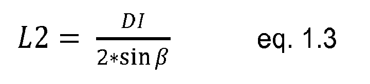
- Since the environment in the
reactor chamber 2 can be described as quite chaotic the length L2 may be varied to some extent. Hence, the length L2 should preferably be in the range:
- The end position EP1 is located a horizontal distance of L1 plus L2 from the reactor
chamber inlet wall 40. - In
Fig. 2a a trajectory path TP1 illustrates how a non-combustible object in the form of a piece of tramp material, for example a nail, is introduced in thereactor chamber 2 by thematerial inlet duct 28, moves towards thefirst target zone 44, enters aninlet opening 48 of firstparticle extraction device 30 and is captured, and thereafter disposed of, as described hereinbefore with reference toFig. 1 . Returning toFig. 2a , afirst barrier row 50 of fluidizinggas nozzles 14 are arranged downstream, as seen in the direction of the horizontal component of the trajectory path TP1, of the inlet opening 48 of the firstparticle extraction device 30. Thebarrier row 50 ofnozzles 14 acts as a barrier to pieces of tramp material, and directs bouncing pieces of tramp material into the firstparticle extraction device 30. The flow of fluidizing gas is reduced above the firstparticle extraction device 30, compared to the rest of thegrate 10, since there are no fluidizing gas nozzles vertically above theextraction device 30. The reduced flow of fluidizing gas above theextraction device 30 reduces the lifting forces on pieces of tramp material, and increases the chance of capturing pieces of tramp material in the firstparticle extraction device 30. Additionally, or alternatively, thegas nozzles 14 located adjacent to theextraction device 30 could be provided with a reduced gas flow, compared to the other gas nozzles of thegrate 10, to further reduce the lifting force in the vicinity of theextraction device 30 for further improved capture of pieces of tramp material. - In accordance with one embodiment the
second target zone 46 starts in a start position SP2 which is a located a horizontal distance L3 from the reactorchamber inlet wall 40, and ends in an end position EP2. Thesecond target zone 46 has a length L4. Hence, the end position EP2 is located a horizontal distance L4 from the start position SP2, and is located a horizontal distance of L3+L4 from the reactorchamber inlet wall 40. In accordance with one exemplary embodiment, thesecond target zone 46 is located in a drop-out zone of thematerial inlet duct 28, where heavier pieces of material may drop-out of theinlet duct 28, following a different shooting trajectory path than non-combustible objects captured at thefirst target zone 44. - The start position SP2 is, in accordance with one embodiment, located adjacent to the reactor
chamber inlet wall 40, which means that the distance L3 is equal to 0. - Since the environment in the
reactor chamber 2 can be described as quite chaotic the distance L3 may be varied to some extent. Hence, the distance L3 should preferably be in the range:
- The length L4 of the
second target zone 46 is, in accordance with one embodiment, calculated according to the following equation, which is based on an estimated drop-out trajectory path ST3 based on thelower end 42 of the inlet duct 28:
- Since the environment in the
reactor chamber 2 can be described as quite chaotic the length L4 may be varied to some extent. Hence, the length L4 should preferably be in the range:
- In
Fig. 2a a trajectory path TP2 illustrates how a relatively heavy piece of tramp material, for example a piece of rock, is introduced in thereactor chamber 2 by theinlet duct 28, drops down towards thesecond target zone 46, enters aninlet opening 52 of secondparticle extraction device 32 and is captured, and thereafter disposed of, as described hereinbefore with reference toFig. 1 . - Also, in some situations bed material may inadvertently accumulate inside the
material inlet duct 28, adjacent to theoutlet 38, to form a pile of material. In such a situation the flow of fuel through thematerial inlet duct 28 may be at least temporarily hindered by such pile of material, which may result in non-combustible objects following trajectory path TP2 rather than trajectory path TP1 in such a situation. - Returning to
Fig. 2a , asecond barrier row 54 of fluidizinggas nozzles 14 are arranged downstream, as seen in the direction of the horizontal component of the trajectory path TP2, of the secondparticle extraction device 32 to direct bouncing pieces of tramp material into the inlet opening 52 of secondparticle extraction device 32. The flow of fluidizing gas is reduced above the secondparticle extraction device 32, compared to the rest of thegrate 10, since there are no fluidizing gas nozzles vertically above theextraction device 32. Additionally, or alternatively, thegas nozzles 14 located adjacent to theextraction device 32 could be provided with a reduced gas flow, compared to the other gas nozzles of thegrate 10, to further reduce the lifting force in the vicinity of theextraction device 32. Similar to what has been described hereinbefore with regard to thefirst extraction device 30, the reduced flow of fluidizing gas above theextraction device 32 increases the chance of capturing pieces of tramp material. - According to one embodiment a horizontal distance between the
first target zone 44 and thesecond target zone 46, i.e., the distance between SP1 and EP2, is at least 300 mm. -
Fig. 2b illustrates thegrate 10 and thematerial inlet duct 28 as seen from above. As illustrated inFig. 2b the inlet opening 48 of the firstparticle extraction device 30 is arranged within thefirst target zone 44 and has a width EW1 and a horizontal length EL1. The width EW1 is typically larger than the length EL1, meaning that theinlet opening 48 has a rectangular shape and extends perpendicular to the longitudinal direction of theinlet duct 28. The width EW1 may be related to the diameter DI of theinlet duct 28. Theinlet opening 52 of the secondparticle extraction device 32 is arranged within thesecond target zone 46 and has a width EW2 and a horizontal length EL2. The width EW2 is typically larger than the length EL2, meaning that theinlet opening 52 has a rectangular shape and extends perpendicular to the longitudinal direction of theinlet duct 28. Theinlet openings grate 10. - The respective lengths EL1 and EL2 may be arranged to allow capture of relatively large non-combustible objects. On the other hand, the larger the length the more is the fluidization on the
grate 10 reduced. Preferably, each of the lengths EL1, EL2 fulfils the following criterion:
- More preferably, each of the lengths EL1, EL2 fulfils the following criterion:

- The respective widths EW1 and EW2 may be designed based on the diameter of the
inlet duct 28, based on principles described hereinafter with reference toFig. 2c . -
Fig. 2c illustrates theinlet duct 28 as seen in cross-section. The maximum solid flow width MAW corresponds to the situation when the entire inner diameter DI of theinlet duct 28 is full with material. A minimum solid flow width MIW corresponds to the situation when the amount of material does not extend up to more than 1/6 of DI, i.e., DI/6, thereby defining for the sector filled with material in such a situation an angle α. - The material supplied to the
reactor chamber 2 via theinlet duct 28 can be expected to spread in the horizontal direction somewhat beyond the width of theinlet duct 28, such width being for acircular inlet duct 28 equal to the diameter DI. In a situation where the flow of material is at the maximum solid flow width MAW and based on the finding that the respective widths EW1 and EW2 need not be larger than about two times the inner diameter DI of theinlet duct 28, the following preferred condition for the widths EW1 and EW2 can be established:
- Furthermore, considering the situation where the flow of material is at a minimum solid flow width MIW, and a situation where it is considered sufficient that the respective width EW1 and EW2 is substantially equal to the width of the material flow MIW, the following preferred condition for the widths EW1 and EW2 can be established:

- Hence, based on the above equations a preferable upper and lower range of the width EW1 of the
opening 48 of the firstparticle extraction device 30 and a preferable upper and lower range of the width EW2 of theopening 52 of the secondparticle extraction device 32 can be calculated. - For an inlet duct having another shape than circular a similar calculation of suitable width EW1, EW2 could be performed. For example, with an inlet duct having a rectangular cross section with a vertical height HS and a horizontal width WS, the material flow would always have the width WS, regardless of the load, and a suitable range for the widths EW1, EW2 could be calculated as:

Hence, the width EW1, EW2 of theparticle extraction device reactor chamber 2. - In the generalized case the minimum width of the material flow could be called WMIN, corresponding to MIW in the circular case and WS in the rectangular case, and the maximum width of the material flow could be called WMAX, corresponding to MAW in the circular case and WS in the rectangular case, wherein the preferable width EW1, EW2 of the respective
particle extraction device 
-
Fig. 3 illustrates agrate 110 according to an alternative embodiment. Thisgrate 110 has afirst target zone 144, the position of which may be established based on shooting trajectory path ST1 and ST2 in accordance with principles similar to those described hereinbefore with regard to thefirst target zone 44 with reference toFig. 2a . Thetarget zone 144 has a horizontal length L2 which is substantially larger than the preferable length of an opening of a particle extraction device. Hence, within thefirst target zone 144 is arranged a rear firstparticle extraction device 130 and a front firstparticle extraction device 131, each of which is provided with alock 134 and is arranged for removal of non-combustible objects, such as tramp material, from thegrate 110 in accordance with principles similar to those described hereinbefore with reference toFig. 1 . The rear firstparticle extraction device 130 is arranged in the rear part of thefirst target zone 144, as seen with respect to the position of the inclinedmaterial inlet duct 128, not shown inFig. 3 , and the front firstparticle extraction device 131 is arranged in the front part of thefirst target zone 144. Each of theextraction devices extraction devices - A
first barrier row 150 of fluidizinggas nozzles 114 are arranged downstream, as seen in the direction of the horizontal component of the trajectory path, of the rear firstparticle extraction device 130. Thebarrier row 150 ofnozzles 114 acts as a barrier to pieces of tramp material, and directs bouncing pieces of tramp material into the inlet opening 148 of the rear firstparticle extraction device 130. At least oneintermediate row 151 of fluidizinggas nozzles 114 is arranged between the rear and front firstparticle extraction devices intermediate row 151 of fluidizinggas nozzles 114 has two purposes. Firstly, theintermediate row 151 ofnozzles 114 provides for fluidisation within thefirst target zone 144. This makes combustion more efficient, and reduces the risk that fuel and/or bed material is collected on thegrate 110, within thefirst target zone 144, due to poor fluidization. Secondly, theintermediate row 151 ofnozzles 114 provides the function of acting as a barrier to pieces of tramp material, and directs bouncing pieces of tramp material into the inlet opening 149 of the front firstparticle extraction device 131. - With reference to
Fig. 3 it has been described how to two firstparticle extraction devices target zone 144, with at least oneintermediate row 151 of fluidizinggas nozzles 114 arranged there between. It will be appreciated that other embodiments are also possible. For example, thefirst target zone 144 could be provided with 3, 4, 5 or even more particle extraction devices arranged in series, and with intermediate rows of fluidizing gas nozzles arranged there between. Furthermore, the intermediate row of fluidizing gas nozzles need not be a single row of nozzles, but could be several rows of nozzles and/or nozzles arranged in another pattern. - Still further, it will be appreciated that the
second target zone 46 illustrated inFigs. 2a and 2b could also be provided with 2, 3 or even more particle extraction devices arranged in series within the second target zone, and with one or more intermediate rows of fluidizing gas nozzles arranged there between, in accordance with the principles described with reference toFig. 3 with respect to thefirst target zone 144. - It will be appreciated that numerous variants of the embodiments described above are possible within the scope of the appended claims.
- Hereinbefore, it has been described that the
reactor chamber 2 is provided with onematerial inlet duct 28. It will be appreciated that it is also possible to provide thereactor chamber 2 with two or more parallel material inlet ducts that may either be arranged adjacent to each other or at a distance from each other. In the latter case, specific first and second target zones are preferably arranged for each one of such parallel material inlet ducts. - Hereinbefore, it has been described that a
barrier row gas nozzles 14 may be arranged downstream of the respective first and secondparticle extraction device particle extraction device particle extraction device extraction devices - To summarize, a circulating fluidized bed boiler reactor chamber (2) comprises a circulating fluidized bed grate (10) for combustion of a fuel in the reactor chamber (2) under fluidized conditions, and a material inlet duct (28) for transporting fuel into the reactor chamber (2) and further to the grate (10). The grate (10) is provided with at least a first particle extraction device (30) for discharge of non-combustible objects from the grate (10). The at least a first particle extraction device (30) is arranged within a first target zone (44) located on the grate (10). The position of the first target zone (44) is based on at least one trajectory path (ST1, ST2) of a non-combustible object entering the reactor chamber (2) via the material inlet duct (28).
- While the invention has been described with reference to a number of preferred embodiments, it will be understood by those skilled in the art that various changes may be made and equivalents may be substituted for elements thereof without departing from the scope of the invention. In addition, many modifications may be made to adapt a particular situation or material to the teachings of the invention without departing from the essential scope thereof. Therefore, it is intended that the invention not be limited to the particular embodiments disclosed as the best mode contemplated for carrying out this invention, but that the invention will include all embodiments falling within the scope of the appended claims. Moreover, the use of the terms first, second, etc. do not denote any order or importance, but rather the terms first, second, etc. are used to distinguish one element from another.
Claims (16)
- A circulating fluidized bed boiler reactor chamber (2) comprising a circulating fluidized bed grate (10) for combustion of a fuel in the reactor chamber (2) under fluidized conditions, and a material inlet duct (28) for transporting fuel into the reactor chamber (2) and further to the grate (10) for being combusted, characterised in the grate (10) being provided with at least a first particle extraction device (30) for discharge of non-combustible objects from the grate (10), wherein the at least a first particle extraction device (30) is arranged within a first target zone (44) located on the grate (10), the position of the first target zone (44) being based on at least one trajectory path (ST1, ST2) of a non-combustible object entering the reactor chamber (2) via the material inlet duct (28).
- A reactor chamber according to claim 1, wherein the material inlet duct (28) is inclined an angle β to the horizontal plane, and a lower end (42) of the material inlet duct (28) enters, via an opening (38) in a reactor chamber inlet wall (40), the reactor chamber (2) at a height HL above the grate (10), wherein the first target zone (44) starts in a start position SP1 which is located a horizontal distance L1 from the opening (38) in the reactor chamber inlet wall (40), the horizontal distance L1 being in the range of:

- A reactor chamber according to any one of the preceding claims, wherein the material inlet duct (28) is inclined an angle β to the horizontal plane, and the material inlet duct (28) has a height of DI, wherein the first target zone (44) has a horizontal length L2 being in the range of:

- A reactor chamber according to any one of the preceding claims, wherein the material inlet duct (28) is inclined an angle β to the horizontal plane, has a height of DI, and a lower end (42) of the inlet duct (28) enters, via an opening (38) in a reactor chamber inlet wall (40), the reactor chamber (2) at a height HL above the grate (10), wherein the first target zone (44) ends in an end position EP1 which is located a horizontal distance L1+L2 from the opening (38) in the reactor chamber inlet wall (40), the horizontal distance L1+L2 being in the range of:

- A reactor chamber according to any one of the preceding claims, wherein an inlet opening (48) of the first particle extraction device (30) has a horizontal length EL1 in the range of:

- A reactor chamber according to any one of the preceding claims, wherein two or more particle extraction devices (130, 131) are arranged within the first target zone (144) at different horizontal distances from the opening in the reactor chamber inlet wall.
- A reactor chamber according to claim 6, wherein the grate (110) comprises at least one intermediate row (151) of fluidizing gas nozzles (114) arranged between two separate particle extraction devices (130, 131).
- A reactor chamber according to any one of the preceding claims, wherein an inlet opening (48) of the first particle extraction device (30) has a width EW1 which is based on the minimum width of the material flow WMIN of the material inlet duct (28) and the maximum width of the material flow WMAX of the material inlet duct (28) and which is in the range of:

- A reactor chamber according to any one of the preceding claims, wherein the grate (10) is provided with at least a second particle extraction device (32) for discharge of non-combustible objects from the grate (10), wherein the at least a second particle extraction device (32) is arranged within a second target zone (46) located on the grate (10) in a position which is separate from the position of the first target zone (44), the position of the second target zone (46) being based on a different trajectory path (ST3) of a non-combustible object entering the reactor chamber (2) via the material inlet duct (28) than the trajectory path (ST1, ST2) on which the position of the first target zone (44) is based.
- A reactor chamber according to claim 9, wherein the material inlet duct (28) is inclined an angle β to the horizontal plane, and a lower end (42) of the inlet duct (28) enters, via an opening (38) in a reactor chamber inlet wall (40), the reactor chamber (2) at a height HL above the grate (10), wherein the second target zone (46) starts in a start position SP2 which is located a horizontal distance L3 from the opening (38) in the reactor chamber inlet wall (40), the horizontal distance L3 being in the range of:

- A reactor chamber according to any one of claims 9-10, wherein the material inlet duct (28) is inclined an angle β to the horizontal plane, and a lower end (42) of the inlet duct (28) enters, via an opening (38) in a reactor chamber inlet wall (40), the reactor chamber (2) at a height HL above the grate (10), wherein the second target zone (46) has a horizontal length L4 being in the range of:

- A reactor chamber according to any one of claims 9-11, wherein the material inlet duct (28) is inclined an angle β to the horizontal plane, and a lower end (42) of the inlet duct (28) enters, via an opening (38) in a reactor chamber inlet wall (40), the reactor chamber (2) at a height HL above the grate (10), wherein the second target zone (46) ends in an end position EP2 which is located a horizontal distance L3+L4 from the opening (38) in the reactor chamber inlet wall (40), the horizontal distance L3+L4 being in the range of:

- A reactor chamber according to any one of the preceding claims, wherein the grate (10) comprises a barrier row (50) of fluidizing gas nozzles (14) arranged downstream, as seen in the flow direction of the fuel supplied from the material inlet duct (28), of the first particle extraction device (30) to act as a barrier to non-combustible objects and to direct bouncing objects into the first particle extraction device (30).
- A method of removing non-combustible objects from a circulating fluidized bed boiler reactor chamber (2) comprising a circulating fluidized bed grate (10) for combustion of a fuel in the reactor chamber (2) under fluidized conditions, and a material inlet duct (28) for transporting fuel into the reactor chamber (2) and further to the grate (10) for being combusted, the method comprising arranging at least a first particle extraction device (30) for discharge of non-combustible objects from the grate (10) within a first target zone (44) located on the grate (10), the position of the first target zone (44) being based on at least one trajectory path (ST1, ST2) of a non-combustible object entering the reactor chamber (2) via the material inlet duct (28), and capturing non-combustible objects by means of the first particle extraction device (30).
- A method according to claim 14, further comprising combusting biofuel in the reactor chamber (2).
- A circulating fluidized bed (CFB) boiler, characterised in comprising a reactor chamber (2) according to any one of claims 1-13.
Priority Applications (1)
| Application Number | Priority Date | Filing Date | Title |
|---|---|---|---|
| EP13152714.5A EP2759767A1 (en) | 2013-01-25 | 2013-01-25 | A reactor chamber for a circulating fluidized bed boiler |
Applications Claiming Priority (1)
| Application Number | Priority Date | Filing Date | Title |
|---|---|---|---|
| EP13152714.5A EP2759767A1 (en) | 2013-01-25 | 2013-01-25 | A reactor chamber for a circulating fluidized bed boiler |
Publications (1)
| Publication Number | Publication Date |
|---|---|
| EP2759767A1 true EP2759767A1 (en) | 2014-07-30 |
Family
ID=47631320
Family Applications (1)
| Application Number | Title | Priority Date | Filing Date |
|---|---|---|---|
| EP13152714.5A Withdrawn EP2759767A1 (en) | 2013-01-25 | 2013-01-25 | A reactor chamber for a circulating fluidized bed boiler |
Country Status (1)
| Country | Link |
|---|---|
| EP (1) | EP2759767A1 (en) |
Cited By (3)
| Publication number | Priority date | Publication date | Assignee | Title |
|---|---|---|---|---|
| CN107036085A (en) * | 2017-06-21 | 2017-08-11 | 清华大学 | A kind of stepped air-distribution device of the sheet of CFBB |
| CN112377898A (en) * | 2020-12-07 | 2021-02-19 | 太原锅炉集团有限公司 | Deslagging system for improving quality of circulating fluidized bed boiler bed and control method thereof |
| CN116357963A (en) * | 2023-03-20 | 2023-06-30 | 神华神东电力有限责任公司 | Slag cooler control device, slag cooler control method and boiler system |
Citations (5)
| Publication number | Priority date | Publication date | Assignee | Title |
|---|---|---|---|---|
| GB2077614A (en) * | 1980-06-16 | 1981-12-23 | Ahlstroem Oy | Fluidized bed combuster |
| US4382415A (en) * | 1980-12-05 | 1983-05-10 | York-Shipley, Inc. | Fluidized bed reactor utilizing a bottomless plate grid and method of operating the reactor |
| EP0597458A1 (en) * | 1992-11-11 | 1994-05-18 | Kawasaki Jukogyo Kabushiki Kaisha | Fluidized-bed incinerator |
| DE19647429A1 (en) * | 1995-11-15 | 1997-05-22 | Ebara Corp | Reactor with fluidised bed |
| US6263837B1 (en) | 1997-09-12 | 2001-07-24 | Foster Wheeler Energia Oy | Grate construction of a fluidized bed boiler |
-
2013
- 2013-01-25 EP EP13152714.5A patent/EP2759767A1/en not_active Withdrawn
Patent Citations (5)
| Publication number | Priority date | Publication date | Assignee | Title |
|---|---|---|---|---|
| GB2077614A (en) * | 1980-06-16 | 1981-12-23 | Ahlstroem Oy | Fluidized bed combuster |
| US4382415A (en) * | 1980-12-05 | 1983-05-10 | York-Shipley, Inc. | Fluidized bed reactor utilizing a bottomless plate grid and method of operating the reactor |
| EP0597458A1 (en) * | 1992-11-11 | 1994-05-18 | Kawasaki Jukogyo Kabushiki Kaisha | Fluidized-bed incinerator |
| DE19647429A1 (en) * | 1995-11-15 | 1997-05-22 | Ebara Corp | Reactor with fluidised bed |
| US6263837B1 (en) | 1997-09-12 | 2001-07-24 | Foster Wheeler Energia Oy | Grate construction of a fluidized bed boiler |
Cited By (4)
| Publication number | Priority date | Publication date | Assignee | Title |
|---|---|---|---|---|
| CN107036085A (en) * | 2017-06-21 | 2017-08-11 | 清华大学 | A kind of stepped air-distribution device of the sheet of CFBB |
| CN107036085B (en) * | 2017-06-21 | 2022-12-23 | 清华大学 | A sheet-shaped stepped air distribution device for a circulating fluidized bed boiler |
| CN112377898A (en) * | 2020-12-07 | 2021-02-19 | 太原锅炉集团有限公司 | Deslagging system for improving quality of circulating fluidized bed boiler bed and control method thereof |
| CN116357963A (en) * | 2023-03-20 | 2023-06-30 | 神华神东电力有限责任公司 | Slag cooler control device, slag cooler control method and boiler system |
Similar Documents
| Publication | Publication Date | Title |
|---|---|---|
| JP6260058B2 (en) | Stoker-type incinerator | |
| JP2573553B2 (en) | Fluidized bed reactor | |
| JPS63501378A (en) | Fluidized bed combustion device with integral solid separator | |
| KR102126663B1 (en) | Exhaust gas treatment device | |
| JP2020190374A (en) | Incinerator and control method of incinerator | |
| US8425850B1 (en) | Large particle ash mitigation system | |
| JP2019147142A (en) | Exhaust gas treatment device | |
| RU2132017C1 (en) | Device for impact-type solid particles separator (versions) | |
| CN1130541A (en) | Reduced height internal impact type particle separator | |
| US5101742A (en) | Fluidized bed combustion | |
| DE974292C (en) | Traveling grate firing with a fly ash remover | |
| WO2009150302A2 (en) | Steering funnel for bed material in fluidized bed boiler, fluidized bed boiler and method in fluidized bed boiler | |
| KR20170131412A (en) | Conveying device | |
| KR102214685B1 (en) | Guide Device for Fallen Coal for Power Plants | |
| JP3514592B2 (en) | Foreign matter discharging device and foreign matter discharging method for circulating fluidized bed combustion device | |
| KR20130107399A (en) | The bio boiler with the facility which removes the dust to the automatic | |
| KR102015928B1 (en) | Fly ash capture apparatus | |
| RU2272218C1 (en) | Method of burning fuel | |
| TWI691679B (en) | Solid fuel burner and combustion device | |
| DE3333929A1 (en) | METHOD AND DEVICE FOR SEPARATING FOREIGN BODIES FROM FLUID BED PARTICLES | |
| DE102012001400A1 (en) | Steam generator plant with afterburning chamber | |
| EP2530379B1 (en) | Burner for a biomass fuel boiler and biomass fuel boiler | |
| DE3818006C2 (en) | ||
| JP7167651B2 (en) | sintering machine | |
| KR101511109B1 (en) | Apparatus for Reduction and Dust-Shelter by Transferring of Falling Coal in System for Drying Coal |
Legal Events
| Date | Code | Title | Description |
|---|---|---|---|
| PUAI | Public reference made under article 153(3) epc to a published international application that has entered the european phase |
Free format text: ORIGINAL CODE: 0009012 |
|
| 17P | Request for examination filed |
Effective date: 20130125 |
|
| AK | Designated contracting states |
Kind code of ref document: A1 Designated state(s): AL AT BE BG CH CY CZ DE DK EE ES FI FR GB GR HR HU IE IS IT LI LT LU LV MC MK MT NL NO PL PT RO RS SE SI SK SM TR |
|
| AX | Request for extension of the european patent |
Extension state: BA ME |
|
| R17P | Request for examination filed (corrected) |
Effective date: 20140708 |
|
| RBV | Designated contracting states (corrected) |
Designated state(s): AL AT BE BG CH CY CZ DE DK EE ES FI FR GB GR HR HU IE IS IT LI LT LU LV MC MK MT NL NO PL PT RO RS SE SI SK SM TR |
|
| RAP1 | Party data changed (applicant data changed or rights of an application transferred) |
Owner name: GENERAL ELECTRIC TECHNOLOGY GMBH |
|
| STAA | Information on the status of an ep patent application or granted ep patent |
Free format text: STATUS: EXAMINATION IS IN PROGRESS |
|
| 17Q | First examination report despatched |
Effective date: 20200608 |
|
| RAP3 | Party data changed (applicant data changed or rights of an application transferred) |
Owner name: GENERAL ELECTRIC TECHNOLOGY GMBH |
|
| GRAP | Despatch of communication of intention to grant a patent |
Free format text: ORIGINAL CODE: EPIDOSNIGR1 |
|
| STAA | Information on the status of an ep patent application or granted ep patent |
Free format text: STATUS: GRANT OF PATENT IS INTENDED |
|
| RIC1 | Information provided on ipc code assigned before grant |
Ipc: F27B 15/02 20060101ALI20210824BHEP Ipc: F23C 10/24 20060101ALI20210824BHEP Ipc: F23C 10/10 20060101ALI20210824BHEP Ipc: F26B 15/02 20060101AFI20210824BHEP |
|
| INTG | Intention to grant announced |
Effective date: 20210910 |
|
| STAA | Information on the status of an ep patent application or granted ep patent |
Free format text: STATUS: THE APPLICATION IS DEEMED TO BE WITHDRAWN |
|
| 18D | Application deemed to be withdrawn |
Effective date: 20220121 |