EP2759709A1 - Compressor - Google Patents
Compressor Download PDFInfo
- Publication number
- EP2759709A1 EP2759709A1 EP12833548.6A EP12833548A EP2759709A1 EP 2759709 A1 EP2759709 A1 EP 2759709A1 EP 12833548 A EP12833548 A EP 12833548A EP 2759709 A1 EP2759709 A1 EP 2759709A1
- Authority
- EP
- European Patent Office
- Prior art keywords
- rotor
- rotor chamber
- cradle
- chamber
- compressor according
- Prior art date
- Legal status (The legal status is an assumption and is not a legal conclusion. Google has not performed a legal analysis and makes no representation as to the accuracy of the status listed.)
- Granted
Links
- 230000006835 compression Effects 0.000 claims abstract description 58
- 238000007906 compression Methods 0.000 claims abstract description 58
- 238000007789 sealing Methods 0.000 claims description 76
- 239000000463 material Substances 0.000 claims description 11
- 230000008859 change Effects 0.000 claims description 6
- 230000000149 penetrating effect Effects 0.000 abstract 1
- 238000006073 displacement reaction Methods 0.000 description 21
- 230000002349 favourable effect Effects 0.000 description 9
- 239000003507 refrigerant Substances 0.000 description 9
- 230000008878 coupling Effects 0.000 description 5
- 238000010168 coupling process Methods 0.000 description 5
- 238000005859 coupling reaction Methods 0.000 description 5
- 239000012530 fluid Substances 0.000 description 4
- 238000005259 measurement Methods 0.000 description 4
- 238000000034 method Methods 0.000 description 4
- 230000008569 process Effects 0.000 description 4
- 238000003754 machining Methods 0.000 description 3
- 238000004088 simulation Methods 0.000 description 2
- 238000004378 air conditioning Methods 0.000 description 1
- 230000009286 beneficial effect Effects 0.000 description 1
- 238000006243 chemical reaction Methods 0.000 description 1
- 238000010586 diagram Methods 0.000 description 1
- 238000004519 manufacturing process Methods 0.000 description 1
- 230000002093 peripheral effect Effects 0.000 description 1
- 230000010349 pulsation Effects 0.000 description 1
- 230000009467 reduction Effects 0.000 description 1
- 238000005057 refrigeration Methods 0.000 description 1
Images




Classifications
-
- F—MECHANICAL ENGINEERING; LIGHTING; HEATING; WEAPONS; BLASTING
- F04—POSITIVE - DISPLACEMENT MACHINES FOR LIQUIDS; PUMPS FOR LIQUIDS OR ELASTIC FLUIDS
- F04C—ROTARY-PISTON, OR OSCILLATING-PISTON, POSITIVE-DISPLACEMENT MACHINES FOR LIQUIDS; ROTARY-PISTON, OR OSCILLATING-PISTON, POSITIVE-DISPLACEMENT PUMPS
- F04C18/00—Rotary-piston pumps specially adapted for elastic fluids
- F04C18/30—Rotary-piston pumps specially adapted for elastic fluids having the characteristics covered by two or more of groups F04C18/02, F04C18/08, F04C18/22, F04C18/24, F04C18/48, or having the characteristics covered by one of these groups together with some other type of movement between co-operating members
- F04C18/40—Rotary-piston pumps specially adapted for elastic fluids having the characteristics covered by two or more of groups F04C18/02, F04C18/08, F04C18/22, F04C18/24, F04C18/48, or having the characteristics covered by one of these groups together with some other type of movement between co-operating members having the movement defined in group F04C18/08 or F04C18/22 and having a hinged member
- F04C18/44—Rotary-piston pumps specially adapted for elastic fluids having the characteristics covered by two or more of groups F04C18/02, F04C18/08, F04C18/22, F04C18/24, F04C18/48, or having the characteristics covered by one of these groups together with some other type of movement between co-operating members having the movement defined in group F04C18/08 or F04C18/22 and having a hinged member with vanes hinged to the inner member
-
- F—MECHANICAL ENGINEERING; LIGHTING; HEATING; WEAPONS; BLASTING
- F01—MACHINES OR ENGINES IN GENERAL; ENGINE PLANTS IN GENERAL; STEAM ENGINES
- F01C—ROTARY-PISTON OR OSCILLATING-PISTON MACHINES OR ENGINES
- F01C21/00—Component parts, details or accessories not provided for in groups F01C1/00 - F01C20/00
- F01C21/08—Rotary pistons
- F01C21/0809—Construction of vanes or vane holders
-
- F—MECHANICAL ENGINEERING; LIGHTING; HEATING; WEAPONS; BLASTING
- F04—POSITIVE - DISPLACEMENT MACHINES FOR LIQUIDS; PUMPS FOR LIQUIDS OR ELASTIC FLUIDS
- F04C—ROTARY-PISTON, OR OSCILLATING-PISTON, POSITIVE-DISPLACEMENT MACHINES FOR LIQUIDS; ROTARY-PISTON, OR OSCILLATING-PISTON, POSITIVE-DISPLACEMENT PUMPS
- F04C18/00—Rotary-piston pumps specially adapted for elastic fluids
- F04C18/30—Rotary-piston pumps specially adapted for elastic fluids having the characteristics covered by two or more of groups F04C18/02, F04C18/08, F04C18/22, F04C18/24, F04C18/48, or having the characteristics covered by one of these groups together with some other type of movement between co-operating members
- F04C18/40—Rotary-piston pumps specially adapted for elastic fluids having the characteristics covered by two or more of groups F04C18/02, F04C18/08, F04C18/22, F04C18/24, F04C18/48, or having the characteristics covered by one of these groups together with some other type of movement between co-operating members having the movement defined in group F04C18/08 or F04C18/22 and having a hinged member
- F04C18/46—Rotary-piston pumps specially adapted for elastic fluids having the characteristics covered by two or more of groups F04C18/02, F04C18/08, F04C18/22, F04C18/24, F04C18/48, or having the characteristics covered by one of these groups together with some other type of movement between co-operating members having the movement defined in group F04C18/08 or F04C18/22 and having a hinged member with vanes hinged to the outer member
-
- F—MECHANICAL ENGINEERING; LIGHTING; HEATING; WEAPONS; BLASTING
- F04—POSITIVE - DISPLACEMENT MACHINES FOR LIQUIDS; PUMPS FOR LIQUIDS OR ELASTIC FLUIDS
- F04C—ROTARY-PISTON, OR OSCILLATING-PISTON, POSITIVE-DISPLACEMENT MACHINES FOR LIQUIDS; ROTARY-PISTON, OR OSCILLATING-PISTON, POSITIVE-DISPLACEMENT PUMPS
- F04C23/00—Combinations of two or more pumps, each being of rotary-piston or oscillating-piston type, specially adapted for elastic fluids; Pumping installations specially adapted for elastic fluids; Multi-stage pumps specially adapted for elastic fluids
- F04C23/001—Combinations of two or more pumps, each being of rotary-piston or oscillating-piston type, specially adapted for elastic fluids; Pumping installations specially adapted for elastic fluids; Multi-stage pumps specially adapted for elastic fluids of similar working principle
-
- F—MECHANICAL ENGINEERING; LIGHTING; HEATING; WEAPONS; BLASTING
- F04—POSITIVE - DISPLACEMENT MACHINES FOR LIQUIDS; PUMPS FOR LIQUIDS OR ELASTIC FLUIDS
- F04C—ROTARY-PISTON, OR OSCILLATING-PISTON, POSITIVE-DISPLACEMENT MACHINES FOR LIQUIDS; ROTARY-PISTON, OR OSCILLATING-PISTON, POSITIVE-DISPLACEMENT PUMPS
- F04C27/00—Sealing arrangements in rotary-piston pumps specially adapted for elastic fluids
Definitions
- the present invention relates to a compressor.
- a swash plate compressor As conventional positive displacement compressors, in which the volume of a compression chamber is changed by rotation of a drive shaft, a swash plate compressor, a vane compressor, and a scroll compressor have been known.
- a swash plate compressor pistons are reciprocated at a stroke corresponding to the inclination angle of the swash plate.
- a vane compressor vanes protrude from and retract into a rotor while sliding along the inner circumferential surface of the housing.
- a scroll compressor In a scroll compressor, a movable scroll orbits about a fixed scroll. Refer, for example, to Patent Document 3.
- the compression chamber draws in fluid through a suction port when the volume of the compression chamber is increased and discharges the fluid through a discharge port when the volume is reduced.
- positive displacement compressors can be employed, for example, for vehicle air conditioners.
- Patent Documents 4 and 5 disclose vane compressors that have compression chambers located at radially outer positions and compression chambers located at radially inner positions. Since the radially inner compression chambers can be provided inside a rotor in these vane compressors, the displacement in relation to the entire volume can be increased.
- a compressor that includes a drive shaft, a housing, an annular rotor, and a cradle.
- the drive shaft is rotational about a shaft axis.
- the housing rotationally supports the drive shaft and has a rotor chamber.
- the rotor chamber is annular and is parallel with the shaft axis.
- the annular rotor is located in the rotor chamber.
- the annular rotor has a cradle window radially extending there through and a circumferential surface extending in a direction parallel with the shaft axis. The rotor is rotational together with the drive shaft while sliding on the housing at the circumferential surface.
- the cradle is provided in the cradle window to be allowed to pivot about a pivot axis parallel with the shaft axis.
- the cradle slides on the housing at pivoting ends, which extend in directions parallel with the shaft axis, as the rotor rotates.
- the rotor chamber includes an outer operation chamber located radially outside of the rotor and an inner operation chamber located radially inside of the rotor.
- the cradle and at least one of the outer operation chamber and the inner operation chamber form a compression chamber, which is caused to change its volume by rotation of the rotor, while maintaining the airtightness.
- the housing includes a suction port and a discharge port, which communicate with the compression chamber.
- the drive shaft supported by the housing rotates about the shaft axis to cause the rotor to rotate together with the drive shaft in the rotor chamber.
- the cradle pivots about a pivot axis, which extends in parallel with the shaft axis in the cradle window of the rotor, while rotating in synchronization with the rotor.
- the rotor chamber includes the outer operation chamber and the inner operation chamber, and the cradle and at least one of the outer operation chamber and the inner operation chamber form the compression chamber. As the rotor rotates, the cradle slides along the housing at the pivoting ends, which extend in parallel with the shaft axis.
- the compressor Since the volume of the compression chamber is changed through rotation of the rotor, vibration is unlikely to be generated in the compressor. In addition, the compressor does not require a large number of components. Further, the rotor of the compressor has an annular shape, and the inner operation chamber is provided radially inside of the rotor. Thus, the compressor has a large displacement compared to typical vane compressors. In addition, because of the shape, the cradle is more resistant to load due to friction and less likely to be broken than vanes.
- the compressor of the invention requires no machining of volute grooves.
- the compressor does not require any parts having a significantly complicated shape.
- the displacement can be increased simply by changing the thickness of the housing, the rotor, and the cradle. This allows the size and the weight to be easily reduced.
- the present invention provides a novel positive displacement compressor, which solves various problems present in conventional positive displacement compressors.
- Fig. 11 is a cross-sectional view illustrating a cradle of a compressor according to a third embodiment.
- a compressor includes a front housing member 1 and a shell 3, which are joined to each other with an O-ring 2a in between as shown in Figs. 1 and 2 .
- An outer block 5, an inner block 7, a front plate 9, and a rear plate 11 are fixed inside the front housing member 1 and the shell 3.
- the front housing member 1, the shell 3, the outer block 5, the inner block 7, the front plate 9, and the rear plate 11 function as a housing.
- the left end is defined as a front side
- the right end is defined as a rear side.
- the front housing member 1 has a shaft hole 1 a, which extends along a shaft axis O and through the front housing member 1.
- the front plate 9 has a shaft hole 9a, which is coaxial with the shaft hole 1 a and extends through the front plate 9.
- the rear plate 11 has a bearing recess 11 a, which is coaxial with the shaft holes 1 a and 9a.
- a shaft sealing device 13 is located in the shaft hole 1 a, and a bearing device 15 is located in the shaft hole 9a.
- a bearing device 17 is located in the bearing recess 11 a.
- the shaft sealing device 13 and the bearing devices 15, 17 support a drive shaft 19 such that the drive shaft 19 can rotate about the shaft axis O.
- the front plate 9 is fixed in the front housing member 1 via an O-ring 2b.
- the rear plate 11 is fixed in the shell 3 via an O-ring 2c.
- the outer block 5 is held between the front plate 9 and the rear plate 11 in the shell 3.
- the outer block 5 and the inner block 7 have annular shapes as shown in Figs. 3 to 6 .
- the inner block 7 is arranged in the outer block 5.
- the inner block 7 is fixed to the rear plate 11 by bolts 21.
- a rotor driving recess 9c is provided in a center area of the front plate 9.
- the rotor driving recess 9c accommodates a hub 27b of a coupling member 27, which will be discussed below.
- the outer block 5, the inner block 7, the rear plate 11, and the hub 27b define an annular rotor chamber 23, which is parallel with the shaft axis O.
- the rotor chamber inward surface 23a is designed based on the shaft axis O and pivot axes P of cradles 33, which will be discussed below, and the paths of outer contact surfaces 33b in a simulation of rotation of a rotor 26.
- the rotor chamber outward surface 23b is formed by the outer circumferential surface of the inner block 7.
- the rotor chamber outward surface 23b is designed based on the shaft axis O and the pivot axes P of the cradles 33 and the paths of inner contact surfaces 33c in a simulation of rotation of the rotor 26.
- the rotor chamber front end surface 23c is formed by the rear surface of the peripheral region of the front plate 9 and the rear surface of the hub 27b.
- the rotor chamber rear end surface 23d is formed by the front surface of the rear plate 11.
- the inner block 7 has a shaft hole 7a, which extends along the shaft axis O and is coaxial with the shaft holes 1 a, 9a.
- the drive shaft 19 is received by the shaft hole 7a.
- a ring 27a of the coupling member 27 is fixed to the drive shaft 19 with a key 25.
- the coupling member 27 includes the ring 27a, which has a cylindrical shape extending in parallel with the shaft axis O, and the hub 27b, which extends from the front end of the ring 27a in a radial direction perpendicular to the shaft axis O.
- a plain bearing 31 is provided between the ring 27a and the shaft hole 7a of the inner block 7.
- the rotor 26 is located in the rotor chamber 23.
- the rotor 26 has a rotor outer circumferential surface 28a and a rotor inner circumferential surface 28b.
- the rotor outer circumferential surface 28a extends from the rotor chamber front end surface 23c to the rotor chamber rear end surface 23d, while contacting, from inside, the rotor chamber inward surface 23a.
- the rotor inner circumferential surface 28b extends from the rotor chamber front end surface 23c to the rotor chamber rear end surface 23d, while contacting, from outside, the rotor chamber outward surface 23b.
- the rotor chamber 23 is therefore configured by an outer operation chamber 231, which is located outside the rotor 26, and an inner operation chamber 232, which is located inside the rotor 26.
- a thrust bearing 32 is provided in the rotor driving recess 9c of the front plate 9 to bear the front surface of the hub 27b.
- a guide groove 11 b is formed in the front surface of the rear plate 11 along the rotor 26. The guide groove 11 b slidably accommodates the slider 60.
- a cradle 33 is provided in each cradle window 29.
- Each cradle 33 has a substantially triangular-pole like shape as shown in Fig. 9 and is an integral part extending from the rotor chamber front end surface 23c to the rotor chamber rear end surface 23d.
- Each cradle 33 has pins 33g and 33h, which protrude from the opposite ends in the axial direction.
- the central shaft axis of the pins 33g, 33h is a pivot axis P, which is parallel with the shaft axis O.
- the front pins 33g are supported by the hub 27b, and the rear pins 33h are supported by the slider 60.
- Each cradle 33 has an outer contact surface 33b and an inner contact surface 33c.
- the outer contact surface 33b is shaped as a part of a cylinder at a position outside a part separated away from the pins 33g, 33h.
- the inner contact surface 33c is shaped as a part of a cylinder at a position inside a part separated away from the pins 33g, 33h.
- the outer contact surfaces 33b contact, from inside, the rotor chamber inward surface 23a as shown in Figs. 3 to 6 .
- the inner contact surfaces 33c contact the rotor chamber outward surface 23b from outside.
- the outer contact surface 33b and the inner contact surface 33c are connected to each other by a first sealing surface 33d.
- the first sealing surface 33d is a curved surface that is a part of the cylinder that conforms to the first end 29a of the cradle window 29.
- the outer contact surface 33b and the inner contact surface 33c are connected to each other by a second sealing surface 33e.
- a part of the second sealing surface 33e about the pins 33g, 33h is a curved surface that is a part of the cylinder that conforms to the second end 29b of the cradle window 29.
- the outer contact surface 33b, the inner contact surface 33c, the first sealing surface 33d, and the second sealing surface 33e extend from the rotor chamber front end surface 23c to the rotor chamber rear end surface 23d as shown in Figs. 1 and 2 .
- the cradles 33 divide the rotor chamber 23 into operation chambers together with the rotor 26, while maintaining airtightness of the chambers.
- the outer operation chamber 231 and the cradles 33 define three compression chambers 351
- the inner operation chamber 232 and the cradles 33 define another three compression chambers 352.
- the compression chambers 351, 352 each change in the volume as the rotor 26 rotates.
- the outer block 5 has two suction ports 5a, which extend in parallel with the shaft axis O.
- the outer block 5 has two recesses in the outer circumferential surface, and each recess and the shell 3 form as a discharge port 5b in between.
- Each suction port 5a is connected to a compression chamber 351 in a process of volume increase.
- Each discharge port 5b is connected to a compression chamber 351 in a process of volume decrease.
- the inner block 7 has two suction ports 7b and two discharge ports 7c, which extend in parallel with the shaft axis O.
- Each suction port 7b is connected to a compression chamber 352 in a process of volume increase.
- Each discharge port 7c is connected to a compression chamber 352 in a process of volume decrease.
- a suction chamber 37 is provided between the front housing member 1 and the front plate 9.
- the front plate 9 has suction passages 9b, 9d, which extend there through and communicate with the suction chamber 37.
- the suction passage 9b connects the suction chamber 37 with the suction ports 5a.
- the hub 27b has a suction passage 27c, which extends there through to connect the suction passage 9d with the suction ports 7b.
- the suction chamber 37 is open to the outside through a suction passage 1 b provided in the front housing member 1.
- a discharge chamber 39 is provided between the shell 3 and the rear plate 11.
- the rear plate 11 has discharge passages 11c, 11 d, which extend there through to connect the discharge ports 5b and the discharge chamber 7c with the discharge chamber 39.
- the discharge chamber 39 is open to the outside through a discharge passage 3b provided in the shell 3.
- the compressor When the above described compressor is installed in a vehicle air conditioner, the compressor constitutes a refrigeration circuit, together with a condenser, an expansion valve, and an evaporator.
- the suction passage 1b is connected to the evaporator, and the discharge passage 3b is connected to the condenser.
- the drive shaft 19 is driven by the vehicle engine or a motor.
- each cradle 33 pivot about the pivot axis P in the corresponding cradle window 29 while rotating in synchronization with the rotor 26.
- the rotation of the drive shaft 19 causes the rotor 26 and the cradles 33 to behave as illustrated in Figs. 3 to 6 . Since the compressor has pairs of cradle windows 29 and cradles 33, compression chambers 351 are provided in the outer operation chamber 231, and compression chambers 352 are provided in the inner operation chamber 232.
- each cradle 33 slides on the outer block 5 and the inner block 7 at opposite pivoting ends, which extend in parallel with the shaft axis O, thereby maintaining the airtightness of the compression chambers 351, 352.
- the compression chambers 351, 352 are maintained in a highly airtight state.
- the compression chambers 351, 352 each change in the volume as the rotor 26 rotates.
- the rotor 26 rotates such that the first sealing surface 33d of each cradle 33 is located on the leading side. Accordingly, most of the compression reaction force of the compression chambers 351, 352 are borne by the rotor 26 via the first sealing surfaces 33d. This stabilizes the behavior of the cradles 33.
- each compression chamber 351 draws refrigerant gas via one of the suction ports 5a.
- each compression chamber 352 draws refrigerant gas via one of the suction ports 7b.
- each compression chamber 351 discharges refrigerant gas via one of the discharge ports 5b.
- each compression chamber 352 discharges refrigerant gas via one of the discharge ports 7c. Air conditioning of the passenger compartment is thus performed.
- Fig. 7(A) represents the state of the compression chambers 351, 352 of Fig. 3
- Fig. 7(B) represents the state of the compression chambers 351, 352 of Fig. 4
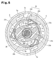
- Fig. 7(C) represents the state of the compression chambers 351, 352 of Fig. 5
- Fig 7(D) represents the state of the compression chambers 351, 352 of Fig. 6 .
- a compression chamber C1 illustrated in Fig. 7(A) which is one of the compression chambers 351 provided in the outer operation chamber 231, is expanded in the state of Fig. 7(B) due to rotation of the drive shaft 19 and draws in refrigerant.
- the compression chamber C1 stops suction of refrigerant at the stage of Fig. 7(C) , and the volume of the compression chamber C1 starts being reduced at the stage of Fig. 7(D) .
- the compression chamber C1 then discharges the refrigerant.
- a compression chamber C2 illustrated in Fig. 7(A) which is one of the compression chambers 352 provided in the inner operation chamber 232, is expanded in the state of Fig. 7(B) due to rotation of the drive shaft 19 and draws in refrigerant.
- the volume of the compression chamber C3 starts being reduced at the stage of Fig. 7(C) .
- the compression chamber C3 then discharges the refrigerant at the stage of Fig. 7(D) .
- the compressor Since the volumes of the compression chambers 351, 352 are changed through rotation of the rotor 26, vibration is unlikely to be generated in the compressor. In addition, the compressor requires a relatively small number of components. Further, the cradles 33 of the compressor have a shape that is not easily broken or deformed when receiving frictional force. Particularly, since the first sealing surface 33d of each cradle 33 coincides with a cylindrical surface having the pivot axis P as the center, high pressure in the compression chambers 351, 352 is borne by the pivot axis P in a favorable manner. This allows the cradle 33 to pivot in a favorable manner. Additionally, having the hollow portion 33f, the cradles 33 are light and can easily pivot in a favorable manner. The compressor is thus beneficial in reduction of power loss.
- the rotor 26 occupies a relatively small space.
- the compressor has the compression chambers 352 located radially inside of the rotor 26. This increases the displacement in relation to the volume of the entire compressor.
- the compressor of the invention requires no machining of volute grooves. Additionally, the compressor does not have parts that have low strength due to complicated shapes such as scrolls. Thus, when extended in the axial measurement to increase the displacement, the displacement can be increased simply by changing the thickness of the housing, the rotor 26, and the cradles 33. This allows the size and weight of the compressor to be easily reduced.
- the compressor since the compressor has sets of a cradle window 29 and a cradle 33, the power loss and pulsation are reduced.
- the outer block 5 and the inner block 7 have the suction ports 5a, 7b and the discharge ports 5b, 7c, the weight of the entire compressor is reduced.
- the novel positive displacement compressor solves various problems present in conventional positive displacement compressor.
- a compressor according to a second embodiment of the present invention employs cradles 43 illustrated in Fig. 10 .
- Each cradle 43 includes a cradle body 44, which has a substantially triangular-pole like shape, an outer sealing pin 45 attached to the cradle body 44, and an inner sealing pin 46 attached to the cradle body 44.
- Each cradle body 44 has pins 43a and 43b, which protrude from the opposite ends in the axial direction. This allows each cradle 43 to pivot about the pivot axis P in the corresponding cradle window 29.
- Each cradle 43 has a hollow portion 43f, which extend in parallel with the shaft axis O.
- the outer sealing pins 45 are made of a material different from that of the outer block 5, which defines the rotor chamber inward surface 23a.
- the outer sealing pins 45 are made of, for example, plastic.
- Each outer sealing pin 45 has a columnar shape extending from the rotor chamber front end surface 23c to the rotor chamber rear end surface 23d. A little more than half the outer circumferential surface of each outer sealing pin 45 is covered by the corresponding cradle body 44. The part of the outer circumferential surface that is exposed from the cradle body 44 functions as an outer contact surface 45a.
- the outer sealing pin 45 is therefore rotational about an outer rotation axis Q1, which is parallel with the shaft axis O and the pivot axis P in the cradle bodies 44. There is no limit to the rotation range of the outer sealing pin 45.
- the inner sealing pins 46 are made of a material different from that of the inner block 7, which defines the rotor chamber outward surface 23b.
- the inner sealing pins 46 are made of, for example, plastic.
- Each inner sealing pin 46 has a columnar shape extending from the rotor chamber front end surface 23c to the rotor chamber rear end surface 23d.
- the inner sealing pin 46 has a lip extending radially outward in a part in the circumferential surface.
- Each inner sealing pin 46 also has a recess 46c, which is recessed inward in the radial direction in a part of the circumferential surface.
- each inner sealing pin 46 While exposing the lip 46a, a little more than half the outer circumferential surface of each inner sealing pin 46 is covered by the corresponding cradle body 44, and the outer surface of the lip 46a functions as an inner contact surface 46b.
- the inner sealing pin 46 is therefore rotational about an inner rotation axis Q2, which is parallel with the shaft axis O and the pivot axis P in the cradle bodies 44.
- the rotation range of the inner sealing pin 46 is limited within the circumferential measurement of the recess 46c.
- the second embodiment is the same as the first embodiment.
- the cradles 43 of the compressor are each configured by a cradle body 44, an outer sealing pin 45, and an inner sealing pin 46.
- the outer sealing pin 45 and the inner sealing pin 46 are separate members from the cradle bodies 44, so that an outer sealing pin 45 and an inner sealing pin 46 having optimal diameters can be selected in relation to dimensional variations in the manufacture of the cradles 43 and the housings.
- the outer contact surface 45a of each outer sealing pins 45 contact, from inside, the rotor chamber inward surface 23a in a favorable manner
- the inner contact surface 46b of each inner sealing pin 46 contact, from outside, the rotor chamber outward surface 23b in a favorable manner.
- each outer sealing pin 45 rotates about the outer rotation axis Q1 relative to the corresponding cradle body 44, so that the outer contact surface 45a of the outer sealing pin 45 rolls on the rotor chamber inward surface 23a in a favorable manner. Further, since each cradle 43 presses the outer contact surface 45a against the rotor chamber inward surface 23a by the centrifugal force based on the rotation of the rotor 26, the outer contact surface 45a and the rotor chamber inward surface 23a are sealed in a favorable manner.
- each inner sealing pin 46 pivots about the inner rotation axis Q2 relative to the corresponding cradle body 44, so that the inner contact surface 45b of the inner sealing pin 46 rolls on the rotor chamber outward surface 23b in a favorable manner.
- each inner sealing pin 46 has a lip 46a, which is bent outward by the differential pressure between the compression chambers 351, 352 located on the leading and trailing sides in the rotation direction of the rotor 26. This reliably causes the lip 46a to contact the rotor chamber outward surface 23b.
- the airtightness of the compression chambers 351, 352 is improved, which improves the compression efficiency.
- the outer sealing pins 45 are made of a material different from that of the outer block 5, seizure between the outer contact surface 45a and the rotor chamber inward surface 23a is prevented.
- the inner sealing pins 46 are made of a material different from that of the inner block 7, seizure between the inner contact surface 46b and the rotor chamber outward surface 23b is prevented.
- the compressor of this embodiment thus has a high durability.
- a compressor according to a third embodiment employs a cradle 53 illustrated in Fig. 11 .
- Each cradle 53 includes a cradle body 54, which substantially has a triangular-pole like shape, an outer sealing pin 55 attached to the cradle body 54, and an inner sealing pin 56 attached to the cradle body 54.
- Each cradle body 54 has pins 53a and 53b, which protrude from the opposite ends in the axial direction. This allows each cradle 53 to pivot about the pivot axis P in the corresponding cradle window 29.
- Each cradle 53 has a hollow portion 53f, which extend in parallel with the shaft axis O.
- the outer sealing pins 55 are made of a material different from that of the outer block 5, which defines the rotor chamber inward surface 23a.
- the outer sealing pins 45 are made of, for example, plastic.
- the structure of the outer sealing pin 55 is the same as that of the second embodiment.
- the inner sealing pins 56 are made of a material different from that of the inner block 7, which defines the rotor chamber outward surface 23b.
- the inner sealing pins 46 are made of, for example, plastic.
- a little more than half the outer circumferential surface of each inner sealing pin 56 is covered by the corresponding cradle body 54, and a part of the outer circumferential surface exposed from the cradle body 54 functions as an inner contact surface 56b.
- the inner sealing pin 56 is therefore rotational about an inner rotation axis Q2, which is parallel with the shaft axis O and the pivot axis P in the cradle bodies 54. There is no limit to the rotation range of the inner sealing pin 56.
- the cradle body 54 has a spring chamber 54a.
- the spring chamber 54a accommodates a coil spring 57, which urges the outer sealing pin 55 and the inner sealing pin 56 away from each other.
- the second embodiment is the same as the first embodiment.
- the compressor of the third embodiment achieves the same advantages as the second embodiment.
- the outer sealing pin 55 and the inner sealing pin 56 are urged away from each other in each cradle 53, so that the outer contact surface 55a of the outer sealing pin 55 contact, from inside, the rotor chamber inward surface 23a and the inner contact surface 56b of the inner sealing pin 56 contacts, from outside, the rotor chamber outward surface 23b in a favorable manner. Accordingly, the airtightness of the compression chambers 351, 352 is improved, which improves the compression efficiency.
- the present invention is not limited to the first to third embodiments, but may be modified as necessary without departing from the scope of the invention. Further, if a motor is used as the drive source in the present invention, the displacement per unit time can be electronically controlled.
Landscapes
- Engineering & Computer Science (AREA)
- Mechanical Engineering (AREA)
- General Engineering & Computer Science (AREA)
- Applications Or Details Of Rotary Compressors (AREA)
Abstract
Description
- The present invention relates to a compressor.
- As conventional positive displacement compressors, in which the volume of a compression chamber is changed by rotation of a drive shaft, a swash plate compressor, a vane compressor, and a scroll compressor have been known. In a swash plate compressor, pistons are reciprocated at a stroke corresponding to the inclination angle of the swash plate. For example, refer to Patent Document 1. In a vane compressor, vanes protrude from and retract into a rotor while sliding along the inner circumferential surface of the housing. For example, refer to Patent Document 2. In a scroll compressor, a movable scroll orbits about a fixed scroll. Refer, for example, to
Patent Document 3. - In these types of positive displacement compressors, the compression chamber draws in fluid through a suction port when the volume of the compression chamber is increased and discharges the fluid through a discharge port when the volume is reduced. Such positive displacement compressors can be employed, for example, for vehicle air conditioners.
- In addition,
Patent Documents 4 and 5 disclose vane compressors that have compression chambers located at radially outer positions and compression chambers located at radially inner positions. Since the radially inner compression chambers can be provided inside a rotor in these vane compressors, the displacement in relation to the entire volume can be increased. -
- Patent Document 1: Japanese Laid-Open Patent Publication No.
2011-122572 - Patent Document 2: Japanese Laid-Open Patent Publication No.
2010-163976 - Patent Document 3: Japanese Laid-Open Patent Publication No.
2011-64189 - Patent Document 4: Japanese Laid-Open Patent Publication No.
59-41602 - Patent Document 5: Japanese Laid-Open Patent Publication No.
1-155091 - Conventional positive displacement compressors have various problems. For example, regarding swash plate compressors, since rotation of the drive shaft is converted into reciprocation of the pistons, vibration tends to be generated. The swash plate compressors also tend to have a great number of components. In this regard, vane compressors and scroll compressors change the volume of compression chambers through rotation of the rotor or the movable scroll, so that the problems of the swash plate compressors are not usually present.
- However, in a typical vane compressor, the rotor occupies a large space, and the displacement in relation to the volume of the entire compressor is relatively small. Although the vane compressors disclosed in
Patent Documents 4, 5 overcome the problem of relatively small displacement, the vanes receive a great load due to frictional force acting on both ends. This may result in breakage or deformation of the vanes. - In scroll compressors, machining of the volute groove in the fixed scroll is difficult. Further, since the fixed scroll has a complex shape, the strength is hard to be ensured. Thus, when extending the axial measurement to increase the displacement, the thickness of the fixed scroll needs to be increased along the entire volute. This increases the size and weight.
- Accordingly, it is an objective of the present invention to provide a novel positive displacement compressor that solves various problems of conventional positive displacement compressors.
- To achieve the foregoing objective and in accordance with one aspect of the present invention, a compressor that includes a drive shaft, a housing, an annular rotor, and a cradle is provided. The drive shaft is rotational about a shaft axis. The housing rotationally supports the drive shaft and has a rotor chamber. The rotor chamber is annular and is parallel with the shaft axis. The annular rotor is located in the rotor chamber. The annular rotor has a cradle window radially extending there through and a circumferential surface extending in a direction parallel with the shaft axis. The rotor is rotational together with the drive shaft while sliding on the housing at the circumferential surface. The cradle is provided in the cradle window to be allowed to pivot about a pivot axis parallel with the shaft axis. The cradle slides on the housing at pivoting ends, which extend in directions parallel with the shaft axis, as the rotor rotates. The rotor chamber includes an outer operation chamber located radially outside of the rotor and an inner operation chamber located radially inside of the rotor. The cradle and at least one of the outer operation chamber and the inner operation chamber form a compression chamber, which is caused to change its volume by rotation of the rotor, while maintaining the airtightness. The housing includes a suction port and a discharge port, which communicate with the compression chamber.
- According to the compressor according to the present invention, the drive shaft supported by the housing rotates about the shaft axis to cause the rotor to rotate together with the drive shaft in the rotor chamber. Accordingly, the cradle pivots about a pivot axis, which extends in parallel with the shaft axis in the cradle window of the rotor, while rotating in synchronization with the rotor. The rotor chamber includes the outer operation chamber and the inner operation chamber, and the cradle and at least one of the outer operation chamber and the inner operation chamber form the compression chamber. As the rotor rotates, the cradle slides along the housing at the pivoting ends, which extend in parallel with the shaft axis. The compression chamber is caused to change its volume by rotation of the rotor, while maintaining the airtightness. Therefore, the compression chamber draws in fluid through the suction port when its volume is increased and discharges the fluid through the discharge port when the volume is reduced. The compressor is employed, for example, for a vehicle air conditioner.
- Since the volume of the compression chamber is changed through rotation of the rotor, vibration is unlikely to be generated in the compressor. In addition, the compressor does not require a large number of components. Further, the rotor of the compressor has an annular shape, and the inner operation chamber is provided radially inside of the rotor. Thus, the compressor has a large displacement compared to typical vane compressors. In addition, because of the shape, the cradle is more resistant to load due to friction and less likely to be broken than vanes.
- Further, unlike scroll compressors, the compressor of the invention requires no machining of volute grooves. The compressor does not require any parts having a significantly complicated shape. Thus, even when extending the axial measurement to increase the displacement, the displacement can be increased simply by changing the thickness of the housing, the rotor, and the cradle. This allows the size and the weight to be easily reduced.
- As described above, the present invention provides a novel positive displacement compressor, which solves various problems present in conventional positive displacement compressors.
-
-
Fig. 1 is an axially cross-sectional view taken along line I-I ofFig. 3 , illustrating a compressor according to a first embodiment of the present invention; -
Fig. 2 is an axially cross-sectional view taken along line II-II ofFig. 3 , illustrating the compressor according to the first embodiment; -
Fig. 3 is a radially cross-sectional view illustrating the compressor according to the first embodiment; -
Fig. 4 is a radially cross-sectional view illustrating the compressor according to the first embodiment; -
Fig. 5 is a radially cross-sectional view illustrating the compressor according to the first embodiment; -
Fig. 6 is a radially cross-sectional view illustrating the compressor according to the first embodiment; -
Figs. 7(A) to 7(D) are explanatory diagrams showing changes in the compression chamber of the compressor according to the first embodiment; -
Fig. 8 is a cross-sectional view illustrating the rotor and the three cradles of the compressor according to the first embodiment; -
Fig. 9 is a plan view illustrating a cradle of the compressor according to the first embodiment; -
Fig. 10 is a cross-sectional view illustrating a cradle of a compressor according to a -
Fig. 11 is a cross-sectional view illustrating a cradle of a compressor according to a third embodiment. - Compressors according to first to third embodiments of the present invention will now be described with reference to the drawings.
- A compressor according to a first embodiment includes a front housing member 1 and a
shell 3, which are joined to each other with an O-ring 2a in between as shown inFigs. 1 and2 . Anouter block 5, aninner block 7, afront plate 9, and arear plate 11 are fixed inside the front housing member 1 and theshell 3. The front housing member 1, theshell 3, theouter block 5, theinner block 7, thefront plate 9, and therear plate 11 function as a housing. InFigs. 1 and2 , the left end is defined as a front side, and the right end is defined as a rear side. - The front housing member 1 has a
shaft hole 1 a, which extends along a shaft axis O and through the front housing member 1. Thefront plate 9 has ashaft hole 9a, which is coaxial with theshaft hole 1 a and extends through thefront plate 9. Therear plate 11 has a bearingrecess 11 a, which is coaxial with the shaft holes 1 a and 9a. Ashaft sealing device 13 is located in theshaft hole 1 a, and abearing device 15 is located in theshaft hole 9a. A bearingdevice 17 is located in the bearingrecess 11 a. Theshaft sealing device 13 and the bearingdevices drive shaft 19 such that thedrive shaft 19 can rotate about the shaft axis O. - The
front plate 9 is fixed in the front housing member 1 via an O-ring 2b. Therear plate 11 is fixed in theshell 3 via an O-ring 2c. Theouter block 5 is held between thefront plate 9 and therear plate 11 in theshell 3. Theouter block 5 and theinner block 7 have annular shapes as shown inFigs. 3 to 6 . Theinner block 7 is arranged in theouter block 5. As shown inFigs. 1 and2 , theinner block 7 is fixed to therear plate 11 bybolts 21. Arotor driving recess 9c is provided in a center area of thefront plate 9. Therotor driving recess 9c accommodates ahub 27b of acoupling member 27, which will be discussed below. Theouter block 5, theinner block 7, therear plate 11, and thehub 27b define anannular rotor chamber 23, which is parallel with the shaft axis O. - The
rotor chamber 23 is defined by a rotor chamberinward surface 23a, which is parallel with the shaft axis O, a rotor chamberoutward surface 23b, which is parallel with the shaft axis O, a rotor chamberfront end surface 23c, which is perpendicular to the shaft axis O, and a rotor chamberrear end surface 23d, which is perpendicular to the shaft axis O. The rotor chamberinward surface 23a is formed by an inner circumferential surface of theouter block 5. The rotor chamberinward surface 23a is designed based on the shaft axis O and pivot axes P ofcradles 33, which will be discussed below, and the paths of outer contact surfaces 33b in a simulation of rotation of arotor 26. The rotor chamberoutward surface 23b is formed by the outer circumferential surface of theinner block 7. The rotor chamberoutward surface 23b is designed based on the shaft axis O and the pivot axes P of thecradles 33 and the paths of inner contact surfaces 33c in a simulation of rotation of therotor 26. The rotor chamberfront end surface 23c is formed by the rear surface of the peripheral region of thefront plate 9 and the rear surface of thehub 27b. The rotor chamberrear end surface 23d is formed by the front surface of therear plate 11. - The
inner block 7 has ashaft hole 7a, which extends along the shaft axis O and is coaxial with the shaft holes 1 a, 9a. Thedrive shaft 19 is received by theshaft hole 7a. Aring 27a of thecoupling member 27 is fixed to thedrive shaft 19 with a key 25. Thecoupling member 27 includes thering 27a, which has a cylindrical shape extending in parallel with the shaft axis O, and thehub 27b, which extends from the front end of thering 27a in a radial direction perpendicular to the shaft axis O. Aplain bearing 31 is provided between thering 27a and theshaft hole 7a of theinner block 7. - The
rotor 26 is located outside thering 27a of thecoupling member 27 and is coaxial with thering 27a. Therotor 26 has a cylindrical shape extending parallel with the shaft axis O. Thehub 27b of thecoupling member 27 is fixed to the front end face of therotor 26 withbolts 26a. The rear end face of thehub 27b serves as the rotor chamberfront end surface 23c, which is flush with the front surface of theouter block 5 and the front surface of theinner block 7. Aslider 60 is fixed to the rear end face of therotor 26 withbolts 26b. Theslider 60 is coaxial with and has the same diameter as therotor 26. Theslider 60 is made of the same material as theplain bearing 31. - The
rotor 26 is located in therotor chamber 23. Therotor 26 has a rotor outercircumferential surface 28a and a rotor innercircumferential surface 28b. As shown inFigs. 3 to 6 , the rotor outercircumferential surface 28a extends from the rotor chamberfront end surface 23c to the rotor chamberrear end surface 23d, while contacting, from inside, the rotor chamberinward surface 23a. The rotor innercircumferential surface 28b extends from the rotor chamberfront end surface 23c to the rotor chamberrear end surface 23d, while contacting, from outside, the rotor chamberoutward surface 23b. Therotor chamber 23 is therefore configured by anouter operation chamber 231, which is located outside therotor 26, and aninner operation chamber 232, which is located inside therotor 26. - As shown in
Figs. 1 and2 , athrust bearing 32 is provided in therotor driving recess 9c of thefront plate 9 to bear the front surface of thehub 27b. Aguide groove 11 b is formed in the front surface of therear plate 11 along therotor 26. Theguide groove 11 b slidably accommodates theslider 60. - The
rotor 26 has threecradle windows 29 extending there through in the radial direction as shown inFig. 8 . Eachcradle window 29 extends in parallel with the shaft axis O from the rotor chamberfront end surface 23c to the rotor chamberrear end surface 23d as shown inFigs. 1 and2 . As shown inFig. 8 , eachcradle window 29 has afirst end 29a in the circumferential direction. Thefirst end 29a is shaped as a part of a cylindrical surface that has a pivot axis P, which is discussed below, as the center. Thecradle window 29 further has asecond end 29b in the circumferential direction. Thesecond end 29b also is shaped as a part of the cylindrical surface that has the pivot axis P as the center. - A
cradle 33 is provided in eachcradle window 29. Eachcradle 33 has a substantially triangular-pole like shape as shown inFig. 9 and is an integral part extending from the rotor chamberfront end surface 23c to the rotor chamberrear end surface 23d. Eachcradle 33 haspins pins Figs. 1 and2 , thefront pins 33g are supported by thehub 27b, and therear pins 33h are supported by theslider 60. This allows eachcradle 33 to pivot about the pivot axis P in thecorresponding cradle window 29. Eachcradle 33 has ahollow portion 33f, which extends from the rotor chamberfront end surface 23c to the rotor chamberrear end surface 23d as shown inFig 9 . - Each
cradle 33 has anouter contact surface 33b and aninner contact surface 33c. Theouter contact surface 33b is shaped as a part of a cylinder at a position outside a part separated away from thepins inner contact surface 33c is shaped as a part of a cylinder at a position inside a part separated away from thepins inward surface 23a as shown inFigs. 3 to 6 . The inner contact surfaces 33c contact the rotor chamberoutward surface 23b from outside. As shown inFig. 9 , theouter contact surface 33b and theinner contact surface 33c are connected to each other by afirst sealing surface 33d. Thefirst sealing surface 33d is a curved surface that is a part of the cylinder that conforms to thefirst end 29a of thecradle window 29. Theouter contact surface 33b and theinner contact surface 33c are connected to each other by asecond sealing surface 33e. A part of thesecond sealing surface 33e about thepins second end 29b of thecradle window 29. Theouter contact surface 33b, theinner contact surface 33c, thefirst sealing surface 33d, and thesecond sealing surface 33e extend from the rotor chamberfront end surface 23c to the rotor chamberrear end surface 23d as shown inFigs. 1 and2 . In this manner, thecradles 33 divide therotor chamber 23 into operation chambers together with therotor 26, while maintaining airtightness of the chambers. Specifically, as shown inFigs. 3 to 6 and7(A) to 7(D) , theouter operation chamber 231 and thecradles 33 define threecompression chambers 351, and theinner operation chamber 232 and thecradles 33 define another threecompression chambers 352. Thecompression chambers rotor 26 rotates. - As shown in
Figs. 3 to 6 , theouter block 5 has twosuction ports 5a, which extend in parallel with the shaft axis O. In addition, theouter block 5 has two recesses in the outer circumferential surface, and each recess and theshell 3 form as adischarge port 5b in between. Eachsuction port 5a is connected to acompression chamber 351 in a process of volume increase. Eachdischarge port 5b is connected to acompression chamber 351 in a process of volume decrease. Theinner block 7 has twosuction ports 7b and twodischarge ports 7c, which extend in parallel with the shaft axis O. Eachsuction port 7b is connected to acompression chamber 352 in a process of volume increase. Eachdischarge port 7c is connected to acompression chamber 352 in a process of volume decrease. - As shown in
Figs. 1 and2 , asuction chamber 37 is provided between the front housing member 1 and thefront plate 9. Thefront plate 9 hassuction passages suction chamber 37. Thesuction passage 9b connects thesuction chamber 37 with thesuction ports 5a. Thehub 27b has asuction passage 27c, which extends there through to connect thesuction passage 9d with thesuction ports 7b. Thesuction chamber 37 is open to the outside through asuction passage 1 b provided in the front housing member 1. - Further, a
discharge chamber 39 is provided between theshell 3 and therear plate 11. Therear plate 11 hasdischarge passages discharge ports 5b and thedischarge chamber 7c with thedischarge chamber 39. Thedischarge chamber 39 is open to the outside through adischarge passage 3b provided in theshell 3. - When the above described compressor is installed in a vehicle air conditioner, the compressor constitutes a refrigeration circuit, together with a condenser, an expansion valve, and an evaporator. The
suction passage 1b is connected to the evaporator, and thedischarge passage 3b is connected to the condenser. Thedrive shaft 19 is driven by the vehicle engine or a motor. - When the
drive shaft 19 rotates about the axis O, therotor 26 is rotated in therotor chamber 23 by thedrive shaft 19. This allows eachcradle 33 to pivot about the pivot axis P in thecorresponding cradle window 29 while rotating in synchronization with therotor 26. The rotation of thedrive shaft 19 causes therotor 26 and thecradles 33 to behave as illustrated inFigs. 3 to 6 . Since the compressor has pairs ofcradle windows 29 and cradles 33,compression chambers 351 are provided in theouter operation chamber 231, andcompression chambers 352 are provided in theinner operation chamber 232. As therotor 26 rotates, eachcradle 33 slides on theouter block 5 and theinner block 7 at opposite pivoting ends, which extend in parallel with the shaft axis O, thereby maintaining the airtightness of thecompression chambers cradles 33 are pressed outward by the centrifugal force based on the rotation of therotor 26, thecompression chambers 351, which are provided in theouter operation chamber 231, are maintained in a highly airtight state. Thus, thecompression chambers rotor 26 rotates. At this time, therotor 26 rotates such that thefirst sealing surface 33d of eachcradle 33 is located on the leading side. Accordingly, most of the compression reaction force of thecompression chambers rotor 26 via thefirst sealing surfaces 33d. This stabilizes the behavior of thecradles 33. - When increasing the volume, each
compression chamber 351 draws refrigerant gas via one of thesuction ports 5a. Likewise, when increasing the volume, eachcompression chamber 352 draws refrigerant gas via one of thesuction ports 7b. When reducing the volume, eachcompression chamber 351 discharges refrigerant gas via one of thedischarge ports 5b. Likewise, when reducing the volume, eachcompression chamber 352 discharges refrigerant gas via one of thedischarge ports 7c. Air conditioning of the passenger compartment is thus performed. - More specifically,
Fig. 7(A) represents the state of thecompression chambers Fig. 3 ,Fig. 7(B) represents the state of thecompression chambers Fig. 4 ,Fig. 7(C) represents the state of thecompression chambers Fig. 5 , andFig 7(D) represents the state of thecompression chambers Fig. 6 . For example, a compression chamber C1 illustrated inFig. 7(A) , which is one of thecompression chambers 351 provided in theouter operation chamber 231, is expanded in the state ofFig. 7(B) due to rotation of thedrive shaft 19 and draws in refrigerant. The compression chamber C1 stops suction of refrigerant at the stage ofFig. 7(C) , and the volume of the compression chamber C1 starts being reduced at the stage ofFig. 7(D) . The compression chamber C1 then discharges the refrigerant. Likewise, a compression chamber C2 illustrated inFig. 7(A) , which is one of thecompression chambers 352 provided in theinner operation chamber 232, is expanded in the state ofFig. 7(B) due to rotation of thedrive shaft 19 and draws in refrigerant. The volume of the compression chamber C3 starts being reduced at the stage ofFig. 7(C) . The compression chamber C3 then discharges the refrigerant at the stage ofFig. 7(D) . - Since the volumes of the
compression chambers rotor 26, vibration is unlikely to be generated in the compressor. In addition, the compressor requires a relatively small number of components. Further, thecradles 33 of the compressor have a shape that is not easily broken or deformed when receiving frictional force. Particularly, since thefirst sealing surface 33d of eachcradle 33 coincides with a cylindrical surface having the pivot axis P as the center, high pressure in thecompression chambers cradle 33 to pivot in a favorable manner. Additionally, having thehollow portion 33f, thecradles 33 are light and can easily pivot in a favorable manner. The compressor is thus beneficial in reduction of power loss. In the compressor, therotor 26 occupies a relatively small space. In addition to thecompression chambers 351 radially outside of therotor 26, the compressor has thecompression chambers 352 located radially inside of therotor 26. This increases the displacement in relation to the volume of the entire compressor. - Further, unlike scroll compressors, the compressor of the invention requires no machining of volute grooves. Additionally, the compressor does not have parts that have low strength due to complicated shapes such as scrolls. Thus, when extended in the axial measurement to increase the displacement, the displacement can be increased simply by changing the thickness of the housing, the
rotor 26, and thecradles 33. This allows the size and weight of the compressor to be easily reduced. - Further, since the compressor has sets of a
cradle window 29 and acradle 33, the power loss and pulsation are reduced. In addition, since theouter block 5 and theinner block 7 have thesuction ports discharge ports - As described above, the novel positive displacement compressor solves various problems present in conventional positive displacement compressor.
- A compressor according to a second embodiment of the present invention employs
cradles 43 illustrated inFig. 10 . Eachcradle 43 includes acradle body 44, which has a substantially triangular-pole like shape, anouter sealing pin 45 attached to thecradle body 44, and aninner sealing pin 46 attached to thecradle body 44. - Each
cradle body 44 haspins cradle 43 to pivot about the pivot axis P in thecorresponding cradle window 29. Eachcradle 43 has ahollow portion 43f, which extend in parallel with the shaft axis O. - The outer sealing pins 45 are made of a material different from that of the
outer block 5, which defines the rotor chamberinward surface 23a. The outer sealing pins 45 are made of, for example, plastic. Eachouter sealing pin 45 has a columnar shape extending from the rotor chamberfront end surface 23c to the rotor chamberrear end surface 23d. A little more than half the outer circumferential surface of eachouter sealing pin 45 is covered by the correspondingcradle body 44. The part of the outer circumferential surface that is exposed from thecradle body 44 functions as anouter contact surface 45a. Theouter sealing pin 45 is therefore rotational about an outer rotation axis Q1, which is parallel with the shaft axis O and the pivot axis P in thecradle bodies 44. There is no limit to the rotation range of theouter sealing pin 45. - The inner sealing pins 46 are made of a material different from that of the
inner block 7, which defines the rotor chamberoutward surface 23b. The inner sealing pins 46 are made of, for example, plastic. Eachinner sealing pin 46 has a columnar shape extending from the rotor chamberfront end surface 23c to the rotor chamberrear end surface 23d. In addition, theinner sealing pin 46 has a lip extending radially outward in a part in the circumferential surface. Eachinner sealing pin 46 also has arecess 46c, which is recessed inward in the radial direction in a part of the circumferential surface. While exposing thelip 46a, a little more than half the outer circumferential surface of eachinner sealing pin 46 is covered by the correspondingcradle body 44, and the outer surface of thelip 46a functions as aninner contact surface 46b. Theinner sealing pin 46 is therefore rotational about an inner rotation axis Q2, which is parallel with the shaft axis O and the pivot axis P in thecradle bodies 44. The rotation range of theinner sealing pin 46 is limited within the circumferential measurement of therecess 46c.. Other than these differences, the second embodiment is the same as the first embodiment. - The compressor of the second embodiment achieves the same advantages as the first embodiment. In addition, the
cradles 43 of the compressor are each configured by acradle body 44, anouter sealing pin 45, and aninner sealing pin 46. Theouter sealing pin 45 and theinner sealing pin 46 are separate members from thecradle bodies 44, so that anouter sealing pin 45 and aninner sealing pin 46 having optimal diameters can be selected in relation to dimensional variations in the manufacture of thecradles 43 and the housings. As a result, theouter contact surface 45a of each outer sealing pins 45 contact, from inside, the rotor chamberinward surface 23a in a favorable manner, and theinner contact surface 46b of eachinner sealing pin 46 contact, from outside, the rotor chamberoutward surface 23b in a favorable manner. - In addition, in the compressor, each
outer sealing pin 45 rotates about the outer rotation axis Q1 relative to thecorresponding cradle body 44, so that theouter contact surface 45a of theouter sealing pin 45 rolls on the rotor chamberinward surface 23a in a favorable manner. Further, since eachcradle 43 presses theouter contact surface 45a against the rotor chamberinward surface 23a by the centrifugal force based on the rotation of therotor 26, theouter contact surface 45a and the rotor chamberinward surface 23a are sealed in a favorable manner. - In contrast, each
inner sealing pin 46 pivots about the inner rotation axis Q2 relative to thecorresponding cradle body 44, so that the inner contact surface 45b of theinner sealing pin 46 rolls on the rotor chamberoutward surface 23b in a favorable manner. In addition, eachinner sealing pin 46 has alip 46a, which is bent outward by the differential pressure between thecompression chambers rotor 26. This reliably causes thelip 46a to contact the rotor chamberoutward surface 23b. - Accordingly, the airtightness of the
compression chambers - Since the outer sealing pins 45 are made of a material different from that of the
outer block 5, seizure between theouter contact surface 45a and the rotor chamberinward surface 23a is prevented. Likewise, since the inner sealing pins 46 are made of a material different from that of theinner block 7, seizure between theinner contact surface 46b and the rotor chamberoutward surface 23b is prevented. The compressor of this embodiment thus has a high durability. - A compressor according to a third embodiment employs a
cradle 53 illustrated inFig. 11 . Eachcradle 53 includes acradle body 54, which substantially has a triangular-pole like shape, anouter sealing pin 55 attached to thecradle body 54, and aninner sealing pin 56 attached to thecradle body 54. - Each
cradle body 54 haspins cradle 53 to pivot about the pivot axis P in thecorresponding cradle window 29. Eachcradle 53 has ahollow portion 53f, which extend in parallel with the shaft axis O. - The outer sealing pins 55 are made of a material different from that of the
outer block 5, which defines the rotor chamberinward surface 23a. The outer sealing pins 45 are made of, for example, plastic. The structure of theouter sealing pin 55 is the same as that of the second embodiment. - The inner sealing pins 56 are made of a material different from that of the
inner block 7, which defines the rotor chamberoutward surface 23b. The inner sealing pins 46 are made of, for example, plastic. A little more than half the outer circumferential surface of eachinner sealing pin 56 is covered by the correspondingcradle body 54, and a part of the outer circumferential surface exposed from thecradle body 54 functions as aninner contact surface 56b. Theinner sealing pin 56 is therefore rotational about an inner rotation axis Q2, which is parallel with the shaft axis O and the pivot axis P in thecradle bodies 54. There is no limit to the rotation range of theinner sealing pin 56. - The
cradle body 54 has aspring chamber 54a. Thespring chamber 54a accommodates acoil spring 57, which urges theouter sealing pin 55 and theinner sealing pin 56 away from each other. Other than these differences, the second embodiment is the same as the first embodiment. - The compressor of the third embodiment achieves the same advantages as the second embodiment. In addition, the
outer sealing pin 55 and theinner sealing pin 56 are urged away from each other in eachcradle 53, so that theouter contact surface 55a of theouter sealing pin 55 contact, from inside, the rotor chamberinward surface 23a and theinner contact surface 56b of theinner sealing pin 56 contacts, from outside, the rotor chamberoutward surface 23b in a favorable manner. Accordingly, the airtightness of thecompression chambers - Although only the first to third embodiments of the present invention have been described so far, the present invention is not limited to the first to third embodiments, but may be modified as necessary without departing from the scope of the invention. Further, if a motor is used as the drive source in the present invention, the displacement per unit time can be electronically controlled.
Claims (17)
- A compressor comprising:a drive shaft that is rotational about a shaft axis;a housing that rotationally supports the drive shaft and has a rotor chamber, wherein the rotor chamber is annular and is parallel with the shaft axis;an annular rotor located in the rotor chamber, wherein the annular rotor has a cradle window radially extending there through and a circumferential surface extending in a direction parallel with the shaft axis, wherein the rotor is rotational together with the drive shaft while sliding on the housing at the circumferential surface; anda cradle that is provided in the cradle window to be allowed to pivot about a pivot axis parallel with the shaft axis, wherein the cradle slides on the housing at pivoting ends, which extend in directions parallel with the shaft axis, as the rotor rotates, whereinthe rotor chamber includesan outer operation chamber located radially outside of the rotor, andan inner operation chamber located radially inside of the rotor,the cradle and at least one of the outer operation chamber and the inner operation chamber form a compression chamber, which is caused to change its volume by rotation of the rotor, while maintaining the airtightness, andthe housing includes a suction port and a discharge port, which communicate with the compression chamber.
- The compressor according to claim 1, wherein
the rotor chamber is defined by
an annular rotor chamber inward surface, which is parallel with the shaft axis,
an annular rotor chamber outward surface, which is surrounded by the rotor chamber inward surface and parallel with the shaft axis,
a rotor chamber front end surface, which is perpendicular to the shaft axis, and
a rotor chamber rear end surface, which is perpendicular to the shaft axis,
the rotor includes
a rotor outer circumferential surface, which extends from the rotor chamber front end surface to the rotor chamber rear end surface, while contacting, from inside, the rotor chamber inward surface, and
a rotor inner circumferential surface, which extends from the rotor chamber front end surface to the rotor chamber rear end surface, while contacting, from outside, the rotor chamber outward surface, and
the cradle includes
an outer contract surface, which contacts, from inside, the rotor chamber inward surface in a range from the rotor chamber front end surface to the rotor chamber rear end surface,
an inner contract surface, which contacts, from outside, the rotor chamber outward surface in a range from the rotor chamber front end surface to the rotor chamber rear end surface,
a first sealing surface, which connects the outer contact surface and the inner contact surface to each other and seals a first end in the circumferential direction of the cradle window, and
a second sealing surface, which connects the outer contact surface and the inner contact surface to each other and seals a second end in the circumferential direction of the cradle window. - The compressor according to claim 2, wherein the distance between the pivot axis and one of the first sealing surface and the second sealing surface is set to be longer than the distance between the pivot axis and the other one of the first sealing surface and the second sealing surface.
- The compressor according to claim 3, wherein one of the first sealing surface and the second sealing surface that is farther from the pivot axis is shaped as a part of a cylindrical surface that has the pivot axis as the center.
- The compressor according to claim 3 or 4, wherein one of the first sealing surface and the second sealing surface that is closer to the pivot axis is shaped as a part of a cylindrical surface that has the pivot axis as the center.
- The compressor according to any one of claims 2 to 5, wherein the housing includes
an outer block that forms the rotor chamber inward surface,
an inner block, which is arranged inside the outer block and forms the rotor chamber outward surface,
a front plate, which is fixed to the outer block and to the inner block, and forms the rotor chamber front end surface, and
a rear plate, which is fixed to the outer block and to the inner block, and forms the rotor chamber rear end surface. - The compressor according to claim 6, wherein the housing includes
a shell, which accommodates the outer block, the inner block, the front plate, and the rear plate, and
a front housing member, which is fixed to the shell and rotationally supports the drive shaft. - The compressor according to any one of claims 2 to 7, wherein
the rotor and the drive shaft are coupled to each other by a hub, which is perpendicular to the shaft axis, and
the hub functions as a part of the rotor chamber front end surface or the rotor chamber rear end surface. - The compressor according to any one of claims 2 to 8, wherein
the cradle includes
a cradle body, which is arranged in the cradle window to be allowed to pivot,
an outer sealing pin, which is provided in the cradle body and has the outer contact surface, and
an inner sealing pin, which is provided in the cradle body and has the inner contact surface. - The compressor according to claim 9, wherein the outer sealing pin is provided in the cradle body to be rotational about an outer rotation axis, which is parallel with the shaft axis and the pivot axis.
- The compressor according to claim 9 or 10, wherein the inner sealing pin is provided in the cradle body to be rotational about an inner rotation axis, which is parallel with the shaft axis and the pivot axis.
- The compressor according to any one of claims 2 to 11, wherein the outer contact surface is made of a material that is different from a material that defines the rotor chamber inward surface.
- The compressor according to any one of claims 2 to 12, wherein the inner contact surface is made of a material that is different from a material that defines the rotor chamber outward surface.
- The compressor according to any one of claims 9 to 11, wherein at least one of the outer sealing pin and the inner sealing pin has a lip, which is pushed by a pressure difference between a leading side and a trailing side in the rotation direction of the rotor and is caused to contact the rotor chamber inward surface or the rotor chamber outward surface.
- The compressor according to any one of claims 1 to 14, wherein the cradle is hollow.
- The compressor according to any one of claims 9 to 11, wherein the cradle has an urging member, which urges the outer sealing pin and the inner sealing pin away from each other.
- The compressor according to any one of claims 1 to 16, further comprising one or more pairs of a cradle window and a cradle.
Applications Claiming Priority (2)
| Application Number | Priority Date | Filing Date | Title |
|---|---|---|---|
| JP2011206044A JP5724785B2 (en) | 2011-09-21 | 2011-09-21 | Compressor |
| PCT/JP2012/072337 WO2013042527A1 (en) | 2011-09-21 | 2012-09-03 | Compressor |
Publications (3)
| Publication Number | Publication Date |
|---|---|
| EP2759709A1 true EP2759709A1 (en) | 2014-07-30 |
| EP2759709A4 EP2759709A4 (en) | 2015-01-28 |
| EP2759709B1 EP2759709B1 (en) | 2015-11-18 |
Family
ID=47914304
Family Applications (1)
| Application Number | Title | Priority Date | Filing Date |
|---|---|---|---|
| EP12833548.6A Not-in-force EP2759709B1 (en) | 2011-09-21 | 2012-09-03 | Compressor |
Country Status (8)
| Country | Link |
|---|---|
| US (1) | US9631621B2 (en) |
| EP (1) | EP2759709B1 (en) |
| JP (1) | JP5724785B2 (en) |
| KR (1) | KR101581692B1 (en) |
| CN (1) | CN103814220B (en) |
| BR (1) | BR112014006255A2 (en) |
| IN (1) | IN2014CN02012A (en) |
| WO (1) | WO2013042527A1 (en) |
Cited By (1)
| Publication number | Priority date | Publication date | Assignee | Title |
|---|---|---|---|---|
| WO2016160856A3 (en) * | 2015-03-30 | 2016-11-10 | Hicor Technologies, Inc. | Compressor |
Families Citing this family (5)
| Publication number | Priority date | Publication date | Assignee | Title |
|---|---|---|---|---|
| JP6563919B2 (en) * | 2013-07-24 | 2019-08-21 | ▲張▼▲翼▼ | Supercharged internal combustion engine with fixed rail rotor pump and fixed rail rotor pump |
| CN103452846B (en) * | 2013-10-08 | 2016-08-03 | 李锦上 | Plug rod compressor |
| CN103867440B (en) * | 2014-03-28 | 2016-04-20 | 袁政 | Compressor |
| CN109268260A (en) * | 2018-11-13 | 2019-01-25 | 白明 | A kind of turbopump |
| KR102881637B1 (en) * | 2020-08-20 | 2025-11-05 | 두원중공업(주) | Centrifugal turbo compressor |
Family Cites Families (22)
| Publication number | Priority date | Publication date | Assignee | Title |
|---|---|---|---|---|
| US1000316A (en) * | 1910-06-15 | 1911-08-08 | William Alexander | Rotary engine. |
| US2435476A (en) * | 1944-04-03 | 1948-02-03 | Orran B Summers | Internal-combustion power unit having a rotor with pivoted impulse elements |
| US2738775A (en) * | 1952-03-10 | 1956-03-20 | Elmer D Smyser | Fluid meters |
| US3083894A (en) * | 1956-07-11 | 1963-04-02 | Borsig Ag | Rotary piston engine |
| JPS5469812A (en) * | 1977-11-15 | 1979-06-05 | Sanyo Electric Co Ltd | Rotary type fluid machine |
| JPS5941602A (en) | 1982-09-01 | 1984-03-07 | Daikin Ind Ltd | Double multivane type rotary machine |
| JPS60111077A (en) | 1983-11-22 | 1985-06-17 | Mitsubishi Heavy Ind Ltd | Rotary pump |
| DE3434501A1 (en) * | 1984-09-20 | 1986-03-27 | SKF GmbH, 8720 Schweinfurt | WING CELL PUMP |
| JPS61160292U (en) | 1985-03-28 | 1986-10-04 | ||
| JPH01100394A (en) | 1987-10-14 | 1989-04-18 | Aisin Seiki Co Ltd | Capacity type pump |
| JPH01155091A (en) | 1987-12-10 | 1989-06-16 | Suzuki Motor Co Ltd | Vane type rotary compressor |
| JPH05509371A (en) | 1990-08-17 | 1993-12-22 | クンタ、ノーバート、ジョセフ | Guide vane hydraulic system |
| JPH0968171A (en) | 1995-09-01 | 1997-03-11 | Kayseven Co Ltd | Pump for fluidized material |
| US6354262B2 (en) * | 1995-09-26 | 2002-03-12 | Christopher Bernard Wade | Rotary engine and compressor |
| JPH10274050A (en) | 1997-03-28 | 1998-10-13 | Masahiko Mori | Rotary piston engine and pump |
| DE102004002151B3 (en) | 2004-01-15 | 2005-09-01 | Gößling, Werner, Ing.(grad.) | Rotary piston blower for compressing and releasing gases comprises blades pivoting on a rotor, and heat exchangers arranged on the rotor between the blades |
| US20100143174A1 (en) * | 2004-03-09 | 2010-06-10 | Maciej Radziwill | Rotary Working Machine Provided with an Assembly of Working Chambers and Periodically Variable Volume, In Particular a Compressor |
| EP1574664B1 (en) * | 2004-03-09 | 2009-04-15 | Radziwill Compressors Sp. z.o.o. | Rotary and oscillating vane machine |
| JP4815880B2 (en) | 2005-06-03 | 2011-11-16 | ダイキン工業株式会社 | Rotary fluid machine |
| JP5201113B2 (en) | 2008-12-03 | 2013-06-05 | 株式会社豊田自動織機 | Scroll compressor |
| JP5083227B2 (en) | 2009-01-15 | 2012-11-28 | 株式会社豊田自動織機 | Back pressure regulating valve for compressor and vane type compressor |
| JP2011122572A (en) | 2009-09-07 | 2011-06-23 | Toyota Industries Corp | Variable displacement swash plate type compressor |
-
2011
- 2011-09-21 JP JP2011206044A patent/JP5724785B2/en not_active Expired - Fee Related
-
2012
- 2012-09-03 WO PCT/JP2012/072337 patent/WO2013042527A1/en not_active Ceased
- 2012-09-03 CN CN201280045412.6A patent/CN103814220B/en not_active Expired - Fee Related
- 2012-09-03 US US14/344,228 patent/US9631621B2/en not_active Expired - Fee Related
- 2012-09-03 KR KR1020147004484A patent/KR101581692B1/en not_active Expired - Fee Related
- 2012-09-03 EP EP12833548.6A patent/EP2759709B1/en not_active Not-in-force
- 2012-09-03 BR BR112014006255A patent/BR112014006255A2/en not_active IP Right Cessation
-
2014
- 2014-03-14 IN IN2012CHN2014 patent/IN2014CN02012A/en unknown
Non-Patent Citations (2)
| Title |
|---|
| No further relevant documents disclosed * |
| See also references of WO2013042527A1 * |
Cited By (2)
| Publication number | Priority date | Publication date | Assignee | Title |
|---|---|---|---|---|
| WO2016160856A3 (en) * | 2015-03-30 | 2016-11-10 | Hicor Technologies, Inc. | Compressor |
| US11306722B2 (en) | 2015-03-30 | 2022-04-19 | Forums Us, Inc. | Compressor with mechanical seal |
Also Published As
| Publication number | Publication date |
|---|---|
| JP2013068122A (en) | 2013-04-18 |
| BR112014006255A2 (en) | 2017-04-11 |
| JP5724785B2 (en) | 2015-05-27 |
| WO2013042527A1 (en) | 2013-03-28 |
| CN103814220B (en) | 2016-01-20 |
| US9631621B2 (en) | 2017-04-25 |
| IN2014CN02012A (en) | 2015-05-29 |
| EP2759709A4 (en) | 2015-01-28 |
| KR20140038562A (en) | 2014-03-28 |
| CN103814220A (en) | 2014-05-21 |
| US20140369880A1 (en) | 2014-12-18 |
| EP2759709B1 (en) | 2015-11-18 |
| KR101581692B1 (en) | 2015-12-31 |
Similar Documents
| Publication | Publication Date | Title |
|---|---|---|
| EP2759709B1 (en) | Compressor | |
| EP1188928A1 (en) | Scroll compressors | |
| JP5442638B2 (en) | Rotary compressor | |
| CN203796562U (en) | Rotating piston type compressor | |
| US20180017056A1 (en) | Cylinder-rotation-type compressor | |
| JP5729342B2 (en) | Tandem vane compressor | |
| US20200248689A1 (en) | Compressor | |
| KR20220044023A (en) | compressor | |
| US11761442B2 (en) | Scroll compressor | |
| CN111255682B (en) | Scroll compressor having a plurality of scroll members | |
| US7866962B2 (en) | Two-stage rotary compressor | |
| US20260110300A1 (en) | Co-rotating scroll compressor | |
| US20190301449A1 (en) | Compressor | |
| EP4290078B1 (en) | Rotary compressor | |
| EP2857688B1 (en) | Rotary compressor | |
| JP2013204556A (en) | Tandem vane compressor | |
| CN110318969B (en) | Piston compressor | |
| CN114320899B (en) | Compressor, air conditioner and vehicle | |
| US20200248690A1 (en) | Compressor | |
| EP3690246A1 (en) | Scroll compressor | |
| CN110762010A (en) | Compression mechanism of rotary compressor and rotary compressor | |
| US20160252084A1 (en) | Variable displacement swash plate type compressor | |
| US20190301450A1 (en) | Compressor | |
| JP2025103092A (en) | Electric Compressor | |
| KR20240133895A (en) | Electric compressor |
Legal Events
| Date | Code | Title | Description |
|---|---|---|---|
| PUAI | Public reference made under article 153(3) epc to a published international application that has entered the european phase |
Free format text: ORIGINAL CODE: 0009012 |
|
| 17P | Request for examination filed |
Effective date: 20140211 |
|
| AK | Designated contracting states |
Kind code of ref document: A1 Designated state(s): AL AT BE BG CH CY CZ DE DK EE ES FI FR GB GR HR HU IE IS IT LI LT LU LV MC MK MT NL NO PL PT RO RS SE SI SK SM TR |
|
| DAX | Request for extension of the european patent (deleted) | ||
| A4 | Supplementary search report drawn up and despatched |
Effective date: 20150109 |
|
| RIC1 | Information provided on ipc code assigned before grant |
Ipc: F01C 21/08 20060101ALI20141223BHEP Ipc: F04C 18/44 20060101AFI20141223BHEP Ipc: F04C 18/46 20060101ALI20141223BHEP Ipc: F04C 21/00 20060101ALI20141223BHEP Ipc: F04C 23/00 20060101ALI20141223BHEP |
|
| REG | Reference to a national code |
Ref country code: DE Ref legal event code: R079 Ref document number: 602012012524 Country of ref document: DE Free format text: PREVIOUS MAIN CLASS: F04C0018400000 Ipc: F04C0018440000 |
|
| RIC1 | Information provided on ipc code assigned before grant |
Ipc: F01C 21/08 20060101ALI20150305BHEP Ipc: F04C 18/46 20060101ALI20150305BHEP Ipc: F04C 21/00 20060101ALI20150305BHEP Ipc: F04C 23/00 20060101ALI20150305BHEP Ipc: F04C 18/44 20060101AFI20150305BHEP |
|
| GRAP | Despatch of communication of intention to grant a patent |
Free format text: ORIGINAL CODE: EPIDOSNIGR1 |
|
| INTG | Intention to grant announced |
Effective date: 20150609 |
|
| GRAS | Grant fee paid |
Free format text: ORIGINAL CODE: EPIDOSNIGR3 |
|
| GRAA | (expected) grant |
Free format text: ORIGINAL CODE: 0009210 |
|
| AK | Designated contracting states |
Kind code of ref document: B1 Designated state(s): AL AT BE BG CH CY CZ DE DK EE ES FI FR GB GR HR HU IE IS IT LI LT LU LV MC MK MT NL NO PL PT RO RS SE SI SK SM TR |
|
| REG | Reference to a national code |
Ref country code: GB Ref legal event code: FG4D |
|
| REG | Reference to a national code |
Ref country code: CH Ref legal event code: EP |
|
| REG | Reference to a national code |
Ref country code: AT Ref legal event code: REF Ref document number: 761726 Country of ref document: AT Kind code of ref document: T Effective date: 20151215 |
|
| REG | Reference to a national code |
Ref country code: IE Ref legal event code: FG4D |
|
| REG | Reference to a national code |
Ref country code: DE Ref legal event code: R096 Ref document number: 602012012524 Country of ref document: DE |
|
| REG | Reference to a national code |
Ref country code: NL Ref legal event code: MP Effective date: 20160218 |
|
| REG | Reference to a national code |
Ref country code: LT Ref legal event code: MG4D |
|
| REG | Reference to a national code |
Ref country code: AT Ref legal event code: MK05 Ref document number: 761726 Country of ref document: AT Kind code of ref document: T Effective date: 20151118 |
|
| PG25 | Lapsed in a contracting state [announced via postgrant information from national office to epo] |
Ref country code: NL Free format text: LAPSE BECAUSE OF FAILURE TO SUBMIT A TRANSLATION OF THE DESCRIPTION OR TO PAY THE FEE WITHIN THE PRESCRIBED TIME-LIMIT Effective date: 20151118 Ref country code: IT Free format text: LAPSE BECAUSE OF FAILURE TO SUBMIT A TRANSLATION OF THE DESCRIPTION OR TO PAY THE FEE WITHIN THE PRESCRIBED TIME-LIMIT Effective date: 20151118 Ref country code: IS Free format text: LAPSE BECAUSE OF FAILURE TO SUBMIT A TRANSLATION OF THE DESCRIPTION OR TO PAY THE FEE WITHIN THE PRESCRIBED TIME-LIMIT Effective date: 20160318 Ref country code: ES Free format text: LAPSE BECAUSE OF FAILURE TO SUBMIT A TRANSLATION OF THE DESCRIPTION OR TO PAY THE FEE WITHIN THE PRESCRIBED TIME-LIMIT Effective date: 20151118 Ref country code: LT Free format text: LAPSE BECAUSE OF FAILURE TO SUBMIT A TRANSLATION OF THE DESCRIPTION OR TO PAY THE FEE WITHIN THE PRESCRIBED TIME-LIMIT Effective date: 20151118 Ref country code: HR Free format text: LAPSE BECAUSE OF FAILURE TO SUBMIT A TRANSLATION OF THE DESCRIPTION OR TO PAY THE FEE WITHIN THE PRESCRIBED TIME-LIMIT Effective date: 20151118 Ref country code: NO Free format text: LAPSE BECAUSE OF FAILURE TO SUBMIT A TRANSLATION OF THE DESCRIPTION OR TO PAY THE FEE WITHIN THE PRESCRIBED TIME-LIMIT Effective date: 20160218 |
|
| PG25 | Lapsed in a contracting state [announced via postgrant information from national office to epo] |
Ref country code: GR Free format text: LAPSE BECAUSE OF FAILURE TO SUBMIT A TRANSLATION OF THE DESCRIPTION OR TO PAY THE FEE WITHIN THE PRESCRIBED TIME-LIMIT Effective date: 20160219 Ref country code: PL Free format text: LAPSE BECAUSE OF FAILURE TO SUBMIT A TRANSLATION OF THE DESCRIPTION OR TO PAY THE FEE WITHIN THE PRESCRIBED TIME-LIMIT Effective date: 20151118 Ref country code: PT Free format text: LAPSE BECAUSE OF FAILURE TO SUBMIT A TRANSLATION OF THE DESCRIPTION OR TO PAY THE FEE WITHIN THE PRESCRIBED TIME-LIMIT Effective date: 20160318 Ref country code: AT Free format text: LAPSE BECAUSE OF FAILURE TO SUBMIT A TRANSLATION OF THE DESCRIPTION OR TO PAY THE FEE WITHIN THE PRESCRIBED TIME-LIMIT Effective date: 20151118 Ref country code: FI Free format text: LAPSE BECAUSE OF FAILURE TO SUBMIT A TRANSLATION OF THE DESCRIPTION OR TO PAY THE FEE WITHIN THE PRESCRIBED TIME-LIMIT Effective date: 20151118 Ref country code: SE Free format text: LAPSE BECAUSE OF FAILURE TO SUBMIT A TRANSLATION OF THE DESCRIPTION OR TO PAY THE FEE WITHIN THE PRESCRIBED TIME-LIMIT Effective date: 20151118 Ref country code: RS Free format text: LAPSE BECAUSE OF FAILURE TO SUBMIT A TRANSLATION OF THE DESCRIPTION OR TO PAY THE FEE WITHIN THE PRESCRIBED TIME-LIMIT Effective date: 20151118 Ref country code: LV Free format text: LAPSE BECAUSE OF FAILURE TO SUBMIT A TRANSLATION OF THE DESCRIPTION OR TO PAY THE FEE WITHIN THE PRESCRIBED TIME-LIMIT Effective date: 20151118 |
|
| PG25 | Lapsed in a contracting state [announced via postgrant information from national office to epo] |
Ref country code: CZ Free format text: LAPSE BECAUSE OF FAILURE TO SUBMIT A TRANSLATION OF THE DESCRIPTION OR TO PAY THE FEE WITHIN THE PRESCRIBED TIME-LIMIT Effective date: 20151118 |
|
| REG | Reference to a national code |
Ref country code: DE Ref legal event code: R097 Ref document number: 602012012524 Country of ref document: DE |
|
| PG25 | Lapsed in a contracting state [announced via postgrant information from national office to epo] |
Ref country code: SK Free format text: LAPSE BECAUSE OF FAILURE TO SUBMIT A TRANSLATION OF THE DESCRIPTION OR TO PAY THE FEE WITHIN THE PRESCRIBED TIME-LIMIT Effective date: 20151118 Ref country code: EE Free format text: LAPSE BECAUSE OF FAILURE TO SUBMIT A TRANSLATION OF THE DESCRIPTION OR TO PAY THE FEE WITHIN THE PRESCRIBED TIME-LIMIT Effective date: 20151118 Ref country code: RO Free format text: LAPSE BECAUSE OF FAILURE TO SUBMIT A TRANSLATION OF THE DESCRIPTION OR TO PAY THE FEE WITHIN THE PRESCRIBED TIME-LIMIT Effective date: 20151118 Ref country code: SM Free format text: LAPSE BECAUSE OF FAILURE TO SUBMIT A TRANSLATION OF THE DESCRIPTION OR TO PAY THE FEE WITHIN THE PRESCRIBED TIME-LIMIT Effective date: 20151118 Ref country code: DK Free format text: LAPSE BECAUSE OF FAILURE TO SUBMIT A TRANSLATION OF THE DESCRIPTION OR TO PAY THE FEE WITHIN THE PRESCRIBED TIME-LIMIT Effective date: 20151118 |
|
| PLBE | No opposition filed within time limit |
Free format text: ORIGINAL CODE: 0009261 |
|
| STAA | Information on the status of an ep patent application or granted ep patent |
Free format text: STATUS: NO OPPOSITION FILED WITHIN TIME LIMIT |
|
| 26N | No opposition filed |
Effective date: 20160819 |
|
| PGFP | Annual fee paid to national office [announced via postgrant information from national office to epo] |
Ref country code: DE Payment date: 20160831 Year of fee payment: 5 |
|
| PG25 | Lapsed in a contracting state [announced via postgrant information from national office to epo] |
Ref country code: SI Free format text: LAPSE BECAUSE OF FAILURE TO SUBMIT A TRANSLATION OF THE DESCRIPTION OR TO PAY THE FEE WITHIN THE PRESCRIBED TIME-LIMIT Effective date: 20151118 |
|
| PG25 | Lapsed in a contracting state [announced via postgrant information from national office to epo] |
Ref country code: BE Free format text: LAPSE BECAUSE OF FAILURE TO SUBMIT A TRANSLATION OF THE DESCRIPTION OR TO PAY THE FEE WITHIN THE PRESCRIBED TIME-LIMIT Effective date: 20151118 |
|
| PG25 | Lapsed in a contracting state [announced via postgrant information from national office to epo] |
Ref country code: MC Free format text: LAPSE BECAUSE OF FAILURE TO SUBMIT A TRANSLATION OF THE DESCRIPTION OR TO PAY THE FEE WITHIN THE PRESCRIBED TIME-LIMIT Effective date: 20151118 |
|
| REG | Reference to a national code |
Ref country code: CH Ref legal event code: PL |
|
| GBPC | Gb: european patent ceased through non-payment of renewal fee |
Effective date: 20160903 |
|
| REG | Reference to a national code |
Ref country code: IE Ref legal event code: MM4A |
|
| REG | Reference to a national code |
Ref country code: FR Ref legal event code: ST Effective date: 20170531 |
|
| PG25 | Lapsed in a contracting state [announced via postgrant information from national office to epo] |
Ref country code: IE Free format text: LAPSE BECAUSE OF NON-PAYMENT OF DUE FEES Effective date: 20160903 Ref country code: LI Free format text: LAPSE BECAUSE OF NON-PAYMENT OF DUE FEES Effective date: 20160930 Ref country code: FR Free format text: LAPSE BECAUSE OF NON-PAYMENT OF DUE FEES Effective date: 20160930 Ref country code: CH Free format text: LAPSE BECAUSE OF NON-PAYMENT OF DUE FEES Effective date: 20160930 Ref country code: GB Free format text: LAPSE BECAUSE OF NON-PAYMENT OF DUE FEES Effective date: 20160903 |
|
| PG25 | Lapsed in a contracting state [announced via postgrant information from national office to epo] |
Ref country code: LU Free format text: LAPSE BECAUSE OF NON-PAYMENT OF DUE FEES Effective date: 20160903 |
|
| REG | Reference to a national code |
Ref country code: DE Ref legal event code: R119 Ref document number: 602012012524 Country of ref document: DE |
|
| PG25 | Lapsed in a contracting state [announced via postgrant information from national office to epo] |
Ref country code: HU Free format text: LAPSE BECAUSE OF FAILURE TO SUBMIT A TRANSLATION OF THE DESCRIPTION OR TO PAY THE FEE WITHIN THE PRESCRIBED TIME-LIMIT; INVALID AB INITIO Effective date: 20120903 |
|
| PG25 | Lapsed in a contracting state [announced via postgrant information from national office to epo] |
Ref country code: CY Free format text: LAPSE BECAUSE OF FAILURE TO SUBMIT A TRANSLATION OF THE DESCRIPTION OR TO PAY THE FEE WITHIN THE PRESCRIBED TIME-LIMIT Effective date: 20151118 Ref country code: MT Free format text: LAPSE BECAUSE OF NON-PAYMENT OF DUE FEES Effective date: 20160930 Ref country code: MK Free format text: LAPSE BECAUSE OF FAILURE TO SUBMIT A TRANSLATION OF THE DESCRIPTION OR TO PAY THE FEE WITHIN THE PRESCRIBED TIME-LIMIT Effective date: 20151118 |
|
| PG25 | Lapsed in a contracting state [announced via postgrant information from national office to epo] |
Ref country code: DE Free format text: LAPSE BECAUSE OF NON-PAYMENT OF DUE FEES Effective date: 20180404 Ref country code: BG Free format text: LAPSE BECAUSE OF FAILURE TO SUBMIT A TRANSLATION OF THE DESCRIPTION OR TO PAY THE FEE WITHIN THE PRESCRIBED TIME-LIMIT Effective date: 20151118 |
|
| PG25 | Lapsed in a contracting state [announced via postgrant information from national office to epo] |
Ref country code: AL Free format text: LAPSE BECAUSE OF FAILURE TO SUBMIT A TRANSLATION OF THE DESCRIPTION OR TO PAY THE FEE WITHIN THE PRESCRIBED TIME-LIMIT Effective date: 20151118 Ref country code: TR Free format text: LAPSE BECAUSE OF FAILURE TO SUBMIT A TRANSLATION OF THE DESCRIPTION OR TO PAY THE FEE WITHIN THE PRESCRIBED TIME-LIMIT Effective date: 20151118 |