EP2759642A1 - Construction machinery and battery pack therefor - Google Patents
Construction machinery and battery pack therefor Download PDFInfo
- Publication number
- EP2759642A1 EP2759642A1 EP12833725.0A EP12833725A EP2759642A1 EP 2759642 A1 EP2759642 A1 EP 2759642A1 EP 12833725 A EP12833725 A EP 12833725A EP 2759642 A1 EP2759642 A1 EP 2759642A1
- Authority
- EP
- European Patent Office
- Prior art keywords
- battery
- limited power
- electric power
- construction machine
- limited
- Prior art date
- Legal status (The legal status is an assumption and is not a legal conclusion. Google has not performed a legal analysis and makes no representation as to the accuracy of the status listed.)
- Granted
Links
Images




Classifications
-
- E—FIXED CONSTRUCTIONS
- E02—HYDRAULIC ENGINEERING; FOUNDATIONS; SOIL SHIFTING
- E02F—DREDGING; SOIL-SHIFTING
- E02F9/00—Component parts of dredgers or soil-shifting machines, not restricted to one of the kinds covered by groups E02F3/00 - E02F7/00
- E02F9/20—Drives; Control devices
- E02F9/2058—Electric or electro-mechanical or mechanical control devices of vehicle sub-units
- E02F9/2091—Control of energy storage means for electrical energy, e.g. battery or capacitors
-
- B—PERFORMING OPERATIONS; TRANSPORTING
- B60—VEHICLES IN GENERAL
- B60L—PROPULSION OF ELECTRICALLY-PROPELLED VEHICLES; SUPPLYING ELECTRIC POWER FOR AUXILIARY EQUIPMENT OF ELECTRICALLY-PROPELLED VEHICLES; ELECTRODYNAMIC BRAKE SYSTEMS FOR VEHICLES IN GENERAL; MAGNETIC SUSPENSION OR LEVITATION FOR VEHICLES; MONITORING OPERATING VARIABLES OF ELECTRICALLY-PROPELLED VEHICLES; ELECTRIC SAFETY DEVICES FOR ELECTRICALLY-PROPELLED VEHICLES
- B60L58/00—Methods or circuit arrangements for monitoring or controlling batteries or fuel cells, specially adapted for electric vehicles
- B60L58/10—Methods or circuit arrangements for monitoring or controlling batteries or fuel cells, specially adapted for electric vehicles for monitoring or controlling batteries
- B60L58/12—Methods or circuit arrangements for monitoring or controlling batteries or fuel cells, specially adapted for electric vehicles for monitoring or controlling batteries responding to state of charge [SoC]
- B60L58/15—Preventing overcharging
-
- E—FIXED CONSTRUCTIONS
- E02—HYDRAULIC ENGINEERING; FOUNDATIONS; SOIL SHIFTING
- E02F—DREDGING; SOIL-SHIFTING
- E02F9/00—Component parts of dredgers or soil-shifting machines, not restricted to one of the kinds covered by groups E02F3/00 - E02F7/00
- E02F9/20—Drives; Control devices
- E02F9/2058—Electric or electro-mechanical or mechanical control devices of vehicle sub-units
- E02F9/2062—Control of propulsion units
- E02F9/207—Control of propulsion units of the type electric propulsion units, e.g. electric motors or generators
-
- E—FIXED CONSTRUCTIONS
- E02—HYDRAULIC ENGINEERING; FOUNDATIONS; SOIL SHIFTING
- E02F—DREDGING; SOIL-SHIFTING
- E02F9/00—Component parts of dredgers or soil-shifting machines, not restricted to one of the kinds covered by groups E02F3/00 - E02F7/00
- E02F9/20—Drives; Control devices
- E02F9/2058—Electric or electro-mechanical or mechanical control devices of vehicle sub-units
- E02F9/2062—Control of propulsion units
- E02F9/2075—Control of propulsion units of the hybrid type
-
- E—FIXED CONSTRUCTIONS
- E02—HYDRAULIC ENGINEERING; FOUNDATIONS; SOIL SHIFTING
- E02F—DREDGING; SOIL-SHIFTING
- E02F9/00—Component parts of dredgers or soil-shifting machines, not restricted to one of the kinds covered by groups E02F3/00 - E02F7/00
- E02F9/26—Indicating devices
-
- H—ELECTRICITY
- H01—ELECTRIC ELEMENTS
- H01M—PROCESSES OR MEANS, e.g. BATTERIES, FOR THE DIRECT CONVERSION OF CHEMICAL ENERGY INTO ELECTRICAL ENERGY
- H01M10/00—Secondary cells; Manufacture thereof
- H01M10/42—Methods or arrangements for servicing or maintenance of secondary cells or secondary half-cells
-
- H—ELECTRICITY
- H02—GENERATION; CONVERSION OR DISTRIBUTION OF ELECTRIC POWER
- H02J—ELECTRIC POWER NETWORKS; CIRCUIT ARRANGEMENTS OR SYSTEMS FOR SUPPLYING OR DISTRIBUTING ELECTRIC POWER; SYSTEMS FOR STORING ELECTRIC ENERGY
- H02J7/00—Circuit arrangements for charging or discharging batteries or for supplying loads from batteries
- H02J7/80—Circuit arrangements for charging or discharging batteries or for supplying loads from batteries including monitoring or indicating arrangements
-
- H—ELECTRICITY
- H02—GENERATION; CONVERSION OR DISTRIBUTION OF ELECTRIC POWER
- H02J—ELECTRIC POWER NETWORKS; CIRCUIT ARRANGEMENTS OR SYSTEMS FOR SUPPLYING OR DISTRIBUTING ELECTRIC POWER; SYSTEMS FOR STORING ELECTRIC ENERGY
- H02J7/00—Circuit arrangements for charging or discharging batteries or for supplying loads from batteries
- H02J7/80—Circuit arrangements for charging or discharging batteries or for supplying loads from batteries including monitoring or indicating arrangements
- H02J7/82—Control of state of charge [SOC]
-
- B—PERFORMING OPERATIONS; TRANSPORTING
- B60—VEHICLES IN GENERAL
- B60L—PROPULSION OF ELECTRICALLY-PROPELLED VEHICLES; SUPPLYING ELECTRIC POWER FOR AUXILIARY EQUIPMENT OF ELECTRICALLY-PROPELLED VEHICLES; ELECTRODYNAMIC BRAKE SYSTEMS FOR VEHICLES IN GENERAL; MAGNETIC SUSPENSION OR LEVITATION FOR VEHICLES; MONITORING OPERATING VARIABLES OF ELECTRICALLY-PROPELLED VEHICLES; ELECTRIC SAFETY DEVICES FOR ELECTRICALLY-PROPELLED VEHICLES
- B60L2200/00—Type of vehicles
- B60L2200/40—Working vehicles
-
- B—PERFORMING OPERATIONS; TRANSPORTING
- B60—VEHICLES IN GENERAL
- B60L—PROPULSION OF ELECTRICALLY-PROPELLED VEHICLES; SUPPLYING ELECTRIC POWER FOR AUXILIARY EQUIPMENT OF ELECTRICALLY-PROPELLED VEHICLES; ELECTRODYNAMIC BRAKE SYSTEMS FOR VEHICLES IN GENERAL; MAGNETIC SUSPENSION OR LEVITATION FOR VEHICLES; MONITORING OPERATING VARIABLES OF ELECTRICALLY-PROPELLED VEHICLES; ELECTRIC SAFETY DEVICES FOR ELECTRICALLY-PROPELLED VEHICLES
- B60L2240/00—Control parameters of input or output; Target parameters
- B60L2240/40—Drive Train control parameters
- B60L2240/54—Drive Train control parameters related to batteries
- B60L2240/547—Voltage
-
- B—PERFORMING OPERATIONS; TRANSPORTING
- B60—VEHICLES IN GENERAL
- B60L—PROPULSION OF ELECTRICALLY-PROPELLED VEHICLES; SUPPLYING ELECTRIC POWER FOR AUXILIARY EQUIPMENT OF ELECTRICALLY-PROPELLED VEHICLES; ELECTRODYNAMIC BRAKE SYSTEMS FOR VEHICLES IN GENERAL; MAGNETIC SUSPENSION OR LEVITATION FOR VEHICLES; MONITORING OPERATING VARIABLES OF ELECTRICALLY-PROPELLED VEHICLES; ELECTRIC SAFETY DEVICES FOR ELECTRICALLY-PROPELLED VEHICLES
- B60L2240/00—Control parameters of input or output; Target parameters
- B60L2240/40—Drive Train control parameters
- B60L2240/54—Drive Train control parameters related to batteries
- B60L2240/549—Current
-
- B—PERFORMING OPERATIONS; TRANSPORTING
- B60—VEHICLES IN GENERAL
- B60L—PROPULSION OF ELECTRICALLY-PROPELLED VEHICLES; SUPPLYING ELECTRIC POWER FOR AUXILIARY EQUIPMENT OF ELECTRICALLY-PROPELLED VEHICLES; ELECTRODYNAMIC BRAKE SYSTEMS FOR VEHICLES IN GENERAL; MAGNETIC SUSPENSION OR LEVITATION FOR VEHICLES; MONITORING OPERATING VARIABLES OF ELECTRICALLY-PROPELLED VEHICLES; ELECTRIC SAFETY DEVICES FOR ELECTRICALLY-PROPELLED VEHICLES
- B60L2250/00—Driver interactions
- B60L2250/16—Driver interactions by display
-
- B—PERFORMING OPERATIONS; TRANSPORTING
- B60—VEHICLES IN GENERAL
- B60L—PROPULSION OF ELECTRICALLY-PROPELLED VEHICLES; SUPPLYING ELECTRIC POWER FOR AUXILIARY EQUIPMENT OF ELECTRICALLY-PROPELLED VEHICLES; ELECTRODYNAMIC BRAKE SYSTEMS FOR VEHICLES IN GENERAL; MAGNETIC SUSPENSION OR LEVITATION FOR VEHICLES; MONITORING OPERATING VARIABLES OF ELECTRICALLY-PROPELLED VEHICLES; ELECTRIC SAFETY DEVICES FOR ELECTRICALLY-PROPELLED VEHICLES
- B60L2260/00—Operating Modes
- B60L2260/20—Drive modes; Transition between modes
- B60L2260/26—Transition between different drive modes
-
- H—ELECTRICITY
- H01—ELECTRIC ELEMENTS
- H01M—PROCESSES OR MEANS, e.g. BATTERIES, FOR THE DIRECT CONVERSION OF CHEMICAL ENERGY INTO ELECTRICAL ENERGY
- H01M10/00—Secondary cells; Manufacture thereof
- H01M10/42—Methods or arrangements for servicing or maintenance of secondary cells or secondary half-cells
- H01M10/48—Accumulators combined with arrangements for measuring, testing or indicating the condition of cells, e.g. the level or density of the electrolyte
-
- H—ELECTRICITY
- H01—ELECTRIC ELEMENTS
- H01M—PROCESSES OR MEANS, e.g. BATTERIES, FOR THE DIRECT CONVERSION OF CHEMICAL ENERGY INTO ELECTRICAL ENERGY
- H01M10/00—Secondary cells; Manufacture thereof
- H01M10/42—Methods or arrangements for servicing or maintenance of secondary cells or secondary half-cells
- H01M10/48—Accumulators combined with arrangements for measuring, testing or indicating the condition of cells, e.g. the level or density of the electrolyte
- H01M10/488—Cells or batteries combined with indicating means for external visualization of the condition, e.g. by change of colour or of light density
-
- H—ELECTRICITY
- H01—ELECTRIC ELEMENTS
- H01M—PROCESSES OR MEANS, e.g. BATTERIES, FOR THE DIRECT CONVERSION OF CHEMICAL ENERGY INTO ELECTRICAL ENERGY
- H01M10/00—Secondary cells; Manufacture thereof
- H01M10/42—Methods or arrangements for servicing or maintenance of secondary cells or secondary half-cells
- H01M10/425—Structural combination with electronic components, e.g. electronic circuits integrated to the outside of the casing
- H01M2010/4271—Battery management systems including electronic circuits, e.g. control of current or voltage to keep battery in healthy state, cell balancing
-
- H—ELECTRICITY
- H01—ELECTRIC ELEMENTS
- H01M—PROCESSES OR MEANS, e.g. BATTERIES, FOR THE DIRECT CONVERSION OF CHEMICAL ENERGY INTO ELECTRICAL ENERGY
- H01M2220/00—Batteries for particular applications
- H01M2220/20—Batteries in motive systems, e.g. vehicle, ship, plane
-
- H—ELECTRICITY
- H02—GENERATION; CONVERSION OR DISTRIBUTION OF ELECTRIC POWER
- H02J—ELECTRIC POWER NETWORKS; CIRCUIT ARRANGEMENTS OR SYSTEMS FOR SUPPLYING OR DISTRIBUTING ELECTRIC POWER; SYSTEMS FOR STORING ELECTRIC ENERGY
- H02J7/00—Circuit arrangements for charging or discharging batteries or for supplying loads from batteries
- H02J7/80—Circuit arrangements for charging or discharging batteries or for supplying loads from batteries including monitoring or indicating arrangements
- H02J7/84—Control of state of health [SOH]
-
- Y—GENERAL TAGGING OF NEW TECHNOLOGICAL DEVELOPMENTS; GENERAL TAGGING OF CROSS-SECTIONAL TECHNOLOGIES SPANNING OVER SEVERAL SECTIONS OF THE IPC; TECHNICAL SUBJECTS COVERED BY FORMER USPC CROSS-REFERENCE ART COLLECTIONS [XRACs] AND DIGESTS
- Y02—TECHNOLOGIES OR APPLICATIONS FOR MITIGATION OR ADAPTATION AGAINST CLIMATE CHANGE
- Y02E—REDUCTION OF GREENHOUSE GAS [GHG] EMISSIONS, RELATED TO ENERGY GENERATION, TRANSMISSION OR DISTRIBUTION
- Y02E60/00—Enabling technologies; Technologies with a potential or indirect contribution to GHG emissions mitigation
- Y02E60/10—Energy storage using batteries
-
- Y—GENERAL TAGGING OF NEW TECHNOLOGICAL DEVELOPMENTS; GENERAL TAGGING OF CROSS-SECTIONAL TECHNOLOGIES SPANNING OVER SEVERAL SECTIONS OF THE IPC; TECHNICAL SUBJECTS COVERED BY FORMER USPC CROSS-REFERENCE ART COLLECTIONS [XRACs] AND DIGESTS
- Y02—TECHNOLOGIES OR APPLICATIONS FOR MITIGATION OR ADAPTATION AGAINST CLIMATE CHANGE
- Y02P—CLIMATE CHANGE MITIGATION TECHNOLOGIES IN THE PRODUCTION OR PROCESSING OF GOODS
- Y02P90/00—Enabling technologies with a potential contribution to greenhouse gas [GHG] emissions mitigation
- Y02P90/60—Electric or hybrid propulsion means for production processes
-
- Y—GENERAL TAGGING OF NEW TECHNOLOGICAL DEVELOPMENTS; GENERAL TAGGING OF CROSS-SECTIONAL TECHNOLOGIES SPANNING OVER SEVERAL SECTIONS OF THE IPC; TECHNICAL SUBJECTS COVERED BY FORMER USPC CROSS-REFERENCE ART COLLECTIONS [XRACs] AND DIGESTS
- Y02—TECHNOLOGIES OR APPLICATIONS FOR MITIGATION OR ADAPTATION AGAINST CLIMATE CHANGE
- Y02T—CLIMATE CHANGE MITIGATION TECHNOLOGIES RELATED TO TRANSPORTATION
- Y02T10/00—Road transport of goods or passengers
- Y02T10/60—Other road transportation technologies with climate change mitigation effect
- Y02T10/70—Energy storage systems for electromobility, e.g. batteries
Definitions
- the present invention relates to a construction machine that converts electric power stored in a battery into motive power.
- the construction machines of this type include a battery-driven hydraulic shovel (battery shovel) having a battery and a motor in place of the engine so that the motor drives a hydraulic pump to operate a hydraulic actuator; a hybrid hydraulic shovel equipped with an engine, a battery, and a generator motor; and a wheel loader and a dump truck each getting the electric power of a battery to drive a traction motor.
- battery-driven hydraulic shovel battery shovel
- a wheel loader and a dump truck each getting the electric power of a battery to drive a traction motor.
- the battery mounted on this type of construction machine provides large-capacity output and is expensive but permits lower energy output per unit weight than kerosene that is used to drive the engine. This poses a big challenge: how to increase the amount of work and extend operation hours by effectively utilizing a limited-capacity battery that can be mounted onboard the machine.
- One construction machine taking the above aspect into account has an inverter device mounted onboard thereby to calculate an amount of electric power stored in an onboard battery so that if the amount of electric power is determined to be low, the maximum output of an onboard electric actuator is reduced (see JP-2009-197514-A ). That is, before and after the amount of electric power is determined to be low, this technique involves the use of a plurality of modes for limiting battery output (the modes may be called the power-limited modes hereunder where appropriate).
- Another technique, related not to construction machines but to electric vehicles involves getting an onboard controller to calculate the amount of electric power(Wh) stored in an onboard battery so that the calculated amount of electric power is displayed on a display device (see JP-8-201488-A ).
- an amount of electric power stored in the battery (remaining electric power) in the currently selected limited power mode is displayed, but an amount of electric power stored in the battery (remaining electric power) corresponding to the other limited power modes not currently selected cannot be displayed. For example, if a first and a second limited power mode are automatically switched and if the first mode is currently selected, a remaining electric power of the second mode cannot be displayed as long as the first mode is being selected.
- one method of calculating the remaining electric power of the battery uses: (1) the state of charge (state of energy) of the battery in question (e.g., charging rate), (2) the voltage of the battery (battery voltage) and its internal resistance, and (3) the clamping voltage and minimum voltage for the construction machine in each of the limited power modes involved.
- the data of the category (1) above is calculated consecutively by a battery control unit (battery management unit) acting as control means for managing the charging and discharging of the battery.
- the data of the category (2) is held by the battery control unit.
- the data of the category (3) is held by a main control unit (construction machine management unit) acting as control means for controlling the construction machine.
- the main control unit is to calculate the remaining electric power
- the data of the category (2) constituting the specifications of the battery is stored beforehand in the main control unit, and the data of the category (1) input consecutively from the battery control unit is used to make the calculation.
- the battery control unit and the battery are frequently integrated to form a battery pack (e.g., of lithium ion battery), so that when the battery is replaced, the battery control unit needs to be replaced as well. That is, when the above-cited method is adopted to calculate the remaining electric power using the main control unit and when the battery is replaced with one having different specifications, it is necessary to overwrite the data of the category (2) stored in the main control unit with the data of the new battery, which can make battery replacement work complicated.
- a battery pack e.g., of lithium ion battery
- An object of the present invention is to provide a construction machine that can display the remaining electric power corresponding to unselected limited power modes and that permits easy battery replacement work.
- the present invention provides a construction machine for converting electric power stored in a battery into motive power.
- the construction machine includes a control section configured to control the construction machine based on a plurality of limited power modes prescribed to control the output of the battery, and calculate the remaining electric power of the battery in each of the limited power modes based on specification information about and the state of energy (state of charge) of the battery and on the limited power and operating voltage prescribed for each of the limited power modes; and a display device configured to display the remaining electric power in each of the limited power modes based on the remaining electric power calculated by the control section.
- the remaining electric power corresponding to the limited power modes not currently selected is displayed. This makes it possible to proceed with work while verifying the actual remaining electric power and permits easier battery replacement work.
- FIG. 1 is an external view of a battery-driven hydraulic shovel (battery shovel) according to one of different embodiments of the present invention.
- the hydraulic shovel in this drawing is equipped with an articulated work device 1A that includes a boom 1a, an arm 1b and a bucket 1c, and a vehicle body 1B that includes an upper swing structure 1d and a lower track structure 1e.
- the boom 1a is supported rotatably by the upper swing structure 1d and driven by a hydraulic cylinder (boom cylinder) 3a.
- the arm 1b is supported rotatably by the boom 1a and driven by a hydraulic cylinder (arm cylinder) 3b.
- the bucket 1c is supported rotatably by the arm 1b and driven by a hydraulic cylinder (bucket cylinder) 3c.
- the upper swing structure 1d is driven swingably by an electric motor (swing motor, not shown), and the lower track structure 1e is driven by a right-hand and a left-hand traction motor (hydraulic motors) 3e and 3f (not shown).
- the hydraulic cylinder 3a, hydraulic cylinder 3b, hydraulic cylinder 3c, and traction motors 3e and 3f are driven with a hydraulic fluid drawn by a hydraulic pump 6 (see Fig. 2 ) from a tank 9.
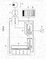
- Fig. 2 is a block diagram of an electrical storage system mounted on a hydraulic shovel according to any one of different embodiments of the present invention.
- the electrical storage system shown in this drawing includes a battery pack 18, a construction machine management unit (main control device (main control section)) 12 that controls the hydraulic shovel based on a plurality of limited power modes (to be discussed later) prescribed to control the output of the battery pack 18, a display device 14 that displays the remaining electric power of the battery pack 18 in meter form 90, a mode switching device 19 that switches to the limited power mode desired by the operator, an inverter device (power conversion device) 16 that converts DC power from the battery pack 18 into AC power for control over a motor 17, the three-phase AC motor (motor) 17 that generates motive power from the electric power of the battery pack 18, and the hydraulic pump 6 driven by the motor 17.
- main control device main control section
- the construction machine management unit 12 has a hardware structure that includes an arithmetic processing unit (e.g., CPU) that executes diverse control programs and a storage device (e.g., ROM, RAM) that stores these control programs and various data (all not shown).
- arithmetic processing unit e.g., CPU
- ROM read-only memory
- RAM random access memory
- the battery pack 18 includes battery modules 10, a battery management unit (battery control device (battery control section)) 11, and a communication line 15 that connects the battery management unit 11 to the battery modules 10.
- the battery pack 18 is detachably mounted on the hydraulic shovel and may be replaced as needed upon battery deterioration, component failure, etc.
- the battery modules 10 are composed of a plurality of individual batteries (battery cells) connected in serial-parallel fashion as needed. Generally, the battery modules 10 are constituted by about 4 to 40 batteries connected in series and are housed in a box. Although the battery pack 18 in Fig. 2 is shown having the battery modules 10 connected in series, the battery modules 10 may be connected alternatively in serial-parallel fashion.
- the battery management unit 11 calculates the state of charge value (SOC), the state of health (SOH), etc., of the battery pack 18 and monitors whether the battery pack 18 is being overcharged or overdischarged.
- the battery management unit 11 has a hardware structure that includes an arithmetic processing unit (e.g., CPU) that executes diverse control programs and a storage device (e.g., ROM, RAM) that stores these control programs and various data (these units not shown).
- the battery management unit 11 of this embodiment calculates a "charging rate" as the value representing the state of charge of the battery pack 18. In this context, the charging rate may be defined as "100% - 100 ⁇ current discharged quantity relative to full charge/full charge capacity.”
- the battery management unit 11 stores open circuit voltages OCV[V] and battery resistance values R[Q] as the specification information about the batteries making up the battery pack 18. Because these values (OCV[V], R[ ⁇ ] vary depending on the state of charge of the batteries, the battery management unit 11 of this embodiment stores in tabular form the relations between charging rates[%] and open circuit voltages OCV[V] and between charging rates[%] and battery resistance values R[Q] (see Figs. 3 and 4 ). The open circuit voltages OCV and battery resistance values R are calculated based on the information in these tables and on the charging rates calculated by the battery management unit 11.
- Fig. 3 is a function table (OCV table) listing open circuit voltages OCV and charging rates in effect for any one of different embodiments of the present invention.
- OCV table the OCV values are shown constituting part of a function table listing the voltages OCV[V] a short time after the batteries have stopped being charged or discharged in association with corresponding charging rates[%].
- the charging rates are given in steps of 10%, each charging rate being set with an OCV.
- the OCV when the charging rate is 15% may be calculated from the OCV values corresponding to the charging rates of 10% and 20%.
- the expression (1) below may be used.
- One way of calculating the charging rate initial value is by making calculations from the OCV table in Fig. 3 based on the voltages before the construction machine is operated. The charging rate while the construction machine is being operated may be calculated using the formula "charging rate initial value + current integration/fully charged capacity ⁇ 100.” Alternatively, while the construction machine is being operated, the open circuit voltage of the batteries may be estimated based on the resistance, and the charging rate may be estimated from the OCV table in Fig. 3 .
- the OCV table in Fig. 3 lists voltages for each of the battery cells configured. For this reason, when the voltage of the entire battery pack 18 is to be calculated, the calculation is performed through multiplication by the number of the batteries contained in the battery pack (e.g., by the number of serially connected batteries).
- One way of setting the OCV table is by changing the charging rate from 0% to 100% in steps of 10%, so as to generate the table based on the voltage obtained after the batteries have been stopped being charged or discharged for two hours.
- the charging rate prior to operation of the hydraulic shovel is first calculated using the OCV table in Fig. 3 ; the charging rate while the machine is in operation is separately calculated; the charging rate upon completion of the machine operation is calculated using the OCV table in Fig. 3 , and the calculated values are put in the expression (2) to find the fully charged capacity.
- the battery management unit 11 is equipped with an ammeter.
- the discharged quantity Q in the expression (2) below needs only to be calculated as an integrated value of the output values (current values) on that ammeter.
- Fig. 4 is a function table (resistance table) listing battery resistance values R and charging rates for any one of different embodiments of the present invention.
- the resistance R is determined by the charging rate[%] and current value[A] (discharging side is regarded as + (plus)) of the battery pack 18. Because the charging rates in this resistance table are given in steps of 10%, calculating the resistance value relative to the charging rate of 15% involves using the charging rates of 10% and 20%, as in the case of Fig. 3 . Meanwhile, the current values are given in steps of 20[A]. Thus calculating the resistance value relative to the current of 30[A] involves using the data of 20[A] and 40[A].
- One way of setting the resistance table is as follows: If the resistance value relative to the current of 20 [A] is to be set when the charging rate is 40%, the current may be set to 20 [A] with the charging rate of 40% and left to that value for some time (e.g., for two minutes), before the difference between the voltage value Vs and the OCV value is divided by the value of 20[A]. Also, because the resistance R becomes larger as the batteries deteriorate, it is preferred that the resistance table be updated as needed in keeping with the deterioration of the batteries.
- the difference between the OCV on the one hand and the voltage while the construction machine is in operation at a constant current for a predetermined time period (e.g., two minutes) on the other hand may be divided by the current to find the resistance value R.
- the value corresponding to the charging rate and current in the resistance table of Fig. 4 is represented by "r”
- the ratio of the resistance to the above value (R/r) may be obtained.
- all resistance values in the table of Fig. 4 may be multiplied by the ratio (R/r) so as to update the resistance table.
- the resistance table of Fig. 4 may also include temperature values in addition to the other factors (charging rates and current values).
- the battery management unit 11 and construction machine management unit 12 are interconnected by a communication line 13.
- the information stored in the management units 11 and 12 e.g., OCV table, resistance table
- the information calculated by the management units 11 and 12 are exchanged over the communication line 13.
- the battery management unit 11 is connected to the battery modules 10 via the communication line 15 and exchanges such information as voltages, temperatures and currents with the battery modules 10.
- the electric power of the battery pack 18 is supplied to the inverter 16.
- the construction machine management unit 12 mainly switches limited power modes in response to the input from the mode switching device 19, controls the hydraulic pump 6 under control of the inverter device 16, and performs display control of the display device 14.
- the construction machine management unit 12 also stores the limited power and operating voltage prescribed for each of a plurality of limited power modes.
- Fig. 5 is a table listing limited power[kWh] and a minimum operating voltage[V] in each of limited power modes of the hydraulic shovel according to any one of different embodiments of the present invention.
- the construction machine management unit 12 stores the number of limited power modes.
- the first limited power mode 34 is a mode (full power mode) in which the hydraulic shovel is operated at full power.
- the second limited power mode 35 is a mode (economy mode (energy-saving mode)) in which power consumption is limited.
- the "limited power” means an upper limit of power over which electric power is not supplied.
- the limited power is set to 50[kW] for full power mode and 30[kW] for economy mode.
- the "minimum operating voltage” is a lower limit of operating voltage below which the operation of the inverter device 16 is not guaranteed. In the example of Fig. 5 , the minimum operating voltage is set to 170[V] for both modes.
- the value of limited power in each limited power mode may be predetermined by the designer or the like. Also, the temperatures of the inverter device 16 and motor 17 may be detected using sensors or the like and the detected temperatures may be used to correct the predetermined limited power values. In such a case, if the temperature of the motor 17 is, for example, 15°C higher than the outdoor temperature, the limited power may be made lower than the default value by 10%.
- the operating voltage of the inverter device 16 is set to be the minimum operating voltage prescribed for each limited power mode.
- an operating voltage predetermined by the designer or the like may be utilized as long as that voltage value is higher than the minimum operating voltage.
- a voltage value lower by 10% than the rated voltage of the motor 17 may be used as the operating voltage.
- a voltage value (170[V]) common to all limited power modes is used as the minimum operating voltage in the example of Fig. 5
- a different operating voltage may be used alternatively in each different limited power mode. Whereas there are two limited power modes in the example of Fig. 5 , it is obvious that three or more limited power modes may be adopted instead.
- the mode switching device 19 is a unit that selects one of a plurality of limited power modes stored in the construction machine management unit 12, and is connected to the construction machine management unit 12.
- the construction machine management unit 12 selects the limited power mode chosen by the operator via the mode switching device 19, and performs drive control of the hydraulic shovel based on the limited power mode thus selected.
- the construction machine management unit 12 is configured to select automatically the limited power mode in accordance with the conditions of the hydraulic shovel (e.g., where the remaining electric power of the battery pack 18 is so low that only the mode of minimum limited power (economy mode of this embodiment) can be selected)
- the mode selected automatically by the construction machine management unit 12 may take precedence over the mode selected by the mode switching device 19.
- the display device 14 is connected to the construction machine management unit 12, and displays the remaining electric power of the battery pack 18 in each of the limited power modes and the remaining operation hours indicative of how long the hydraulic shovel can operate in each limited power mode (e.g., see Fig. 10 to be explained later) on the basis of the input values from the construction machine management unit 12.
- Fig. 6 is a flowchart of a remaining electric power calculation process performed by the construction machine management unit 12 according to the first embodiment of the present invention.
- the flowchart in Fig. 6 is started when the power supply of the hydraulic shovel is turned on from the off-state. Carried out first is the process of inputting the OCV table (see Fig. 3 ) and resistance table (see Fig. 4 ) as the specification information about the battery pack 18 to the construction machine management unit 12 from the battery management unit 11 (step 121).
- the battery management unit 11 then performs the process of calculating the charging rate (state of charge value) and the discharged quantity of the battery pack 18 and outputting the result of the calculations to the construction machine management unit 12.
- the construction machine management unit 12 performs the process of inputting the charging rate in question (step 122).
- the construction machine management unit 12 performs the process of calculating the OCV value and resistance value of the battery pack 18 in the state of charge at that point based on the OCV table, resistance table, and charging rate input from the battery management unit 11 (step 123).
- the construction machine management unit 12 calculates the remaining electric power of the battery pack 18 in each of the limited power modes based on the OCV and resistance of the battery pack 18 calculated in step 123 and on the limited power and operating voltage prescribed for each limited power mode (see Fig. 5 ) (step 124).
- An example of the calculations involved is explained below with reference to Fig. 7 .
- This is a calculation example in which the construction machine management unit 12 automatically selects one of a plurality of limited power modes in accordance with the conditions of the hydraulic shovel (the conditions being the limited power in each limited power mode and the battery voltage of the battery pack 18 in the example below).
- the first limited power mode where the limited power is relatively large is selected in the fully charged state and that the second limited power mode where the limited power is relatively small is automatically selected when the battery voltage of the battery pack 18 reaches the minimum operating voltage in the first limited power mode (i.e., when the discharged quantity of the battery pack 18 has reached x1 (to be discussed later)).
- Fig. 7 is an explanatory drawing of a calculation example in which the remaining electric power is calculated when a limited power mode is automatically selected in accordance with the conditions of the hydraulic shovel.
- a vertical axis 41 denotes the voltage[V] of the battery pack 18 and a horizontal axis 42 represents the discharged quantity[Ah] of the battery pack 18 (integrated value of discharged quantities[Ah] from the fully charged state).
- An indication x0 on the horizontal axis 42 denotes the current discharged quantity.
- a minimum operating voltage 43 represents the value in Fig. 5 (170[V]) set for each limited power mode and stored beforehand in the construction machine management unit 12.
- a first battery voltage curve 44 in Fig. 7 is a curve that applies when the battery pack 18 is discharged at the current in the first limited power mode (corresponding to full power mode in Fig. 5 ).
- the current(I) in the first limited power mode may be obtained as the solution to the expression (3) given below.
- the expression (3) above is turned into a quadratic equation for I.
- the smaller solution is selected here (i.e., of the smaller current (lower than a predetermined limited current)).
- the curve obtained by the expression (4) below constitutes the first battery voltage curve 44 when the current I1 is allowed to flow.
- the discharged quantity x (represented by x1) at which the first battery voltage curve 44 reaches the minimum operating voltage 43.
- the discharged quantity is obtained by solving the expression (5) below.
- the remaining electric power E1 of the battery pack 18 when the hydraulic shovel is driven in the first limited power mode is acquired by integrating the expression (4) for the discharged quantity x over a section between the current discharged quantity x0 and the discharged quantity x1 (area of region 46).
- the total electric power E01 in the first limited power mode i.e., total electric power following discharge from the fully charged state up to x1
- the total electric power E01 may be calculated from the remaining electric power when the hydraulic shovel is started.
- the remaining electric power E2 in the second limited power mode is obtained.
- the remaining energy E2 is acquired in the same manner as the remaining electric power E1 in the first limited power mode.
- a solution (assumed to be I2) of the expression (3) is first obtained, and the second battery voltage curve 47 when the current I2 is allowed to flow is acquired using the expression (6) below. Then the discharged quantity x (assumed to be x2) at which the second battery voltage curve 47 reaches the minimum operating voltage 43 is obtained.
- the total electric power E02 of the battery pack 18 when the hydraulic shovel is driven in the second limited power mode is obtained by integrating the expression (6) for the discharged quantity x over a section between the discharged quantity x1 and the discharged quantity x2 (total area of regions 48 and 49).
- the remaining electric power E2 of the battery pack 18 when the hydraulic shovel is driven in the second limited power mode is obtained by integrating the expression (6) for x over the section between the discharged quantity x1 and the discharged quantity x2 (total area of regions 48 and 49) when x1 > x0 (i.e., when the first limited power mode is selected), or by integrating the expression (6) for x over a section between the discharged quantity x0 and discharged quantity x2 (total area of regions 48 and 49) when x1 ⁇ x0 (i.e., when the second limited power mode is automatically selected).
- Fig. 8 is a table listing the results of calculating total electric power levels E01 and E02 as well as remaining electric power levels E1 and E2 in each of different limited power modes.
- the example in Fig. 8 is made up of two kinds of information: information about a first limited power mode 81 and information about a second limited power mode 82.
- the information about the first limited power mode is composed of total electric power 83 and remaining electric power 84, and so is the information about the second limited power mode made up of the total electric power and remaining electric power.
- the construction machine management unit 12 performs calculations to have the display device 14 display the remaining electric power and remaining operation hours in each limited power mode based on these results of the calculations.
- Fig. 9 is an illustration showing a display screen of the display device 14 when a limited power mode is automatically selected in accordance with the voltage of the battery pack 18. It is assumed here that the first and the second limited power modes are selected in a predetermined order in reference to the limited power of each limited power mode and the voltage of the battery pack 18 as discussed above. Specifically, the first limited power mode is being selected until the battery voltage reaches the operating voltage of the first limited power mode (170 [V]). Beyond that point, the second limited power mode is selected. Also, the display screen shown in Fig. 9 includes a selected mode display part 100, a meter display part 90, a remaining electric power display part 96, and a remaining operation hour display part 97.
- the selected mode display part 100 is a part that displays the limited power mode currently selected by the construction machine management unit 12.
- full power mode first limited power mode
- the remaining electric power display part 96 is a part that displays the remaining electric power of the battery pack 18. What is displayed here is the sum of the remaining electric power levels when the first and the second limited power modes are selected in the above-mentioned order. Whereas the remaining electric power is shown displayed in percentage points[%] relative to the total electric power in the example of Fig. 9 , the remaining electric power may be indicated alternatively in kilowatt-hours[kWh].
- the remaining operation hour display part 97 is a part that displays the remaining operation hours[h] when the hydraulic shovel is operated with average power[W] prescribed for each limited power mode. What is displayed here is the sum of the remaining operation hours when the first and the second limited power modes are selected in the above-mentioned order.
- the meter display part 90 is a part that visually displays currently remaining electric power 92 of the battery pack 18.
- the meter display part 90 is composed of a first meter part 93 that indicates the remaining electric power in the limited power mode (first limited power mode) currently selected by the construction machine management unit 12, a second meter part 94 that indicates the remaining electric power in the limited power mode (second limited power mode) lastly selected by the construction machine management unit 12, and a consumption meter part 91 that indicates the electric power consumed so far.
- the consumption meter part 91 is shown blacked out.
- the currently remaining electric power 92 of the battery pack 18 is the sum of the remaining electric power in the first limited power mode and the remaining electric power in the second limited power mode, the sum being calculated using the expression (7) below.
- the remaining electric power in the second limited power mode in a boundary position 95 between the first meter part 93 and the second meter part 94 is calculated using the expression (8) below.
- the remaining operation hours may also be displayed in meter form.
- the remaining operation hours may be calculated using the expressions (9-1) through (9-3) below, and the remaining electric power in the second limited power mode in the boundary position 95 between the first meter part 93 and the second meter part 94 may be calculated using the expressions (10-1) through (10-3) below.
- the "average electric power in each limited power mode" for use in the calculations of remaining operation hours may be the most recent predetermined value (e.g., for the last five minutes) on the construction machine side, a predetermined value, or an actual value obtained in the past.
- this embodiment displays the sum of the remaining electric power levels in two modes by having the lastly selected second meter part 91 shown topped with the initially selected first meter part 93 in connected fashion. Getting the meter parts displayed connected in the predetermined order makes it easy to grasp the relations between the limited power modes selected at present and in the future on the one hand and the remaining electric power on the other hand.
- the present invention can also be applied to cases where three or more limited power modes are set.
- the display may simply indicate the remaining electric power in the limited power mode currently selected by the construction machine management unit 12 and the remaining electric power in at least one of the remaining limited power modes excluding the currently selected the limited power mode (e.g., the remaining electric power in the mode with the smallest limited power of all limited power modes).
- step 125 After the process of calculating the remaining electric power (remaining operation hours) in each limited power mode is performed in step 124 as described above, another process is carried out (step 125) to output to the display device 14 a display signal for displaying the results of the calculations as shown in Fig. 9 . This causes the display device 14 to display the remaining electric power levels (remaining operation hours) and other information as shown in Fig. 9 .
- step 126 Upon completion of step 125, a process is performed (step 126) to check whether the power supply of the hydraulic shovel is turned off. If the power supply is on, step 122 and subsequent steps are repeated. On the other hand, if the power supply is turned off, the series of the steps above is terminated.
- step 126 be performed by the construction machine management unit 12.
- the series of the steps above may be repeated at intervals of a predetermined set value (e.g., 100[ms] or 1[s]).
- the process of calculating the total electric power in step 124 may be omitted.
- the tables may be stored in a storage device of the construction machine management unit 12, and step 121 may be omitted until the battery pack 18 is replaced next time.
- the display device 14 displays the total remaining electric power including the remaining electric power associated with the limited power mode not currently selected (second limited power mode). This makes it possible to proceed with work while the actual remaining electric power is being verified. Also, the process (step 121) of inputting to the construction machine management unit 12 the information (OCV table and resistance table) for calculating the specification information about the battery pack (battery voltage and internal resistance) is included in the series of the steps for calculating the remaining electric power, which eliminates the need for overwriting the specification information stored in the construction machine management unit 12 concerning the yet-to-be-replaced battery pack with new specification information. This helps facilitate battery replacement work.
- Fig. 10 is a calculation example of a variation of this embodiment in which the remaining electric power is calculated when the first and the second limited power modes are switched manually via the mode switching device 19.
- Fig. 10 is an explanatory drawing of a calculation example in which the remaining electric power is calculated when a limited power mode is manually selected via the mode switching device 19.
- the second limited power mode can be selected as desired even before the discharged quantity reaches x1, so that the remaining electric power is calculated separately for each of the two limited power modes.
- the remaining electric power E1 of the battery pack 18 when the hydraulic shovel is driven in the first limited power mode is calculated in the same manner as discussed above with reference to Fig. 7 .
- the first battery voltage curve 44 is obtained from the expression (4), before being integrated for the discharged quantity x to calculate the remaining electric power (area of region 46).
- the current I2 is obtained using the expression (3) in the same manner as discussed above, and the second battery voltage curve 47 when the current I2 is allowed to flow is acquired using the expression (6). Furthermore, the discharged quantity x2 at which the battery voltage reaches the minimum operating voltage 43 is obtained.
- the remaining electric power E2 in the second limited power mode is obtained by integrating the expression (6) for the discharged quantity x over the section between the discharged quantity x0 and the discharged quantity x2 (total area of regions 46, 48, 49 and 50). Also, the total electric power E02 in the second limited power mode is acquired by integrating the expression (6) for the discharged quantity x from 0 to x2 (total area of regions 45, 46, 48, 49, 50 and 51).
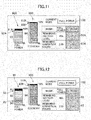
- Fig. 11 is an illustration showing a display screen of the display device 14 when a limited power mode can be manually selected in response to the input from the mode switching device 19.
- the display screen in this drawing includes a selected mode display part 100, a remaining electric power display part 96A, a remaining operation hour display part 97A, a first meter display part 90A, and a second meter display part 90B.
- the remaining electric power display part 96A and remaining operation hour display part 97A are parts that display the remaining electric power and remaining operation hours in each limited power mode.
- the remaining electric power and remaining operation hours associated with the limited power mode not currently selected may be rendered less visible than the remaining electric power and remaining operation hours associated with the currently selected limited power mode (power mode). That is, the indications in the unselected mode may be shown hatched as illustrated, shown translucent, or not shown outright, for example. In the example of Fig. 11 , if the operator manually selects economy mode, the indications in power mode are shown hatched.
- the first meter display part 90A is a part that displays visually the remaining electric power 92A in the limited power mode currently selected by the construction machine management unit 12 (first limited power mode). As such, the first meter display part 90A is composed of a meter part 93 that displays the remaining electric power when the first limited power mode is continuously selected, and a consumption meter part 91A that indicates the electric power consumed so far.
- the second meter display part 90B is a part that displays visually the remaining electric power 92B in the other limited power modes (second limited power mode) excluding the mode currently selected by the construction machine management unit 12.
- the second meter display part 90B is composed of a meter part 94 that displays the remaining electric power when the second limited power mode is continuously selected, and a consumption meter part 91B that indicates the electric power consumed so far.
- the remaining electric power 92A in the first limited power mode may be calculated using the expression (11) below, and the remaining electric power 92B in the second limited power mode may be computed using the expression (12) below.
- the remaining electric power levels are shown displayed in meter form in the illustrated example, the remaining operation hours may be displayed in meter form as discussed above.
- the remaining electric power 92A in the first limited power mode may be calculated using the expression (13) below, and the remaining electric power 92B in the second limited power mode may be computed using the expression (14) below.
- W2 Average power(W) in the second limited power mode
- step 124 After the process of calculating the remaining electric power (remaining operation hours) in each limited power mode is performed in step 124 as described above, another process is carried out (step 125) to output to the display device 14 a display signal for displaying the results of the calculations as shown in Fig. 11 .
- step 125 Another process is carried out (step 125) to output to the display device 14 a display signal for displaying the results of the calculations as shown in Fig. 11 .
- the rest of the processes are the same as those explained above and thus will not be discussed further.
- the remaining electric power in the limited power mode not currently selected is also displayed on the display device 14. This makes it possible easily to grasp the remaining electric power that applies if the hydraulic shovel is operated in the unselected limited power mode. This also allows work to proceed while the actual remaining electric power is being verified. At the same time, it is easy to select a limited power mode in consideration of work details and remaining electric power. Furthermore, because it takes less time and effort to overwrite the information in the construction machine management unit 12, it is easy to replace the batteries.
- Fig. 12 is a display example of another variation of this embodiment in which, with the first and the second limited power modes manually selectable via the mode switching device 19, the second limited power mode is automatically selected if the voltage of the battery pack 18 reaches the operating voltage while the first limited power mode is being selected (this case may be referred to hereunder as the case where a limited power mode is selected semi-automatically).
- Fig. 12 is an illustration showing a display screen of the display device 14 when a limited power mode is semi-automatically selected.
- the display screen shown in this drawing includes a first meter display part 90, a second meter display part 90B, a selected mode display part 100, a remaining electric power display part 96A, and a remaining operation hour display part 97A.
- the first meter display part 90 is the same as the meter display part 90 shown in Fig. 9 . That is, where the first limited power mode is in effect, a drop of the battery voltage to the operating voltage causes the second limited power mode to be automatically selected by specification.
- the remaining electric power levels in the first and the second limited power modes are displayed simultaneously. Where remaining electric power levels are displayed as shown in the illustrated example, the remaining electric power in the first limited power mode may be obtained using the expression (7) above. If operation hours are to be displayed, they may be acquired using the expression (9) above.
- step 124 After the process of calculating the remaining electric power (remaining operation hours) in each limited power mode is performed in step 124 as described above, another process is carried out (step 125) to output to the display device 14 a display signal for displaying the results of the calculations as shown in Fig. 12 .
- step 125 Another process is carried out (step 125) to output to the display device 14 a display signal for displaying the results of the calculations as shown in Fig. 12 .
- step 125 The rest of the processes are the same as those explained above and thus will not be discussed further.
- the effects of the preceding variation are supplemented with the ease in taking into account the remaining electric power associated with the limited power mode (second limited power mode) ultimately selected automatically following the decrease of the battery voltage. This allows work to be carried out while the actual remaining electric power is being considered.
- the meter display part for the currently selected limited power mode and the meter display part for the unselected limited power mode are shown displayed concurrently by specification.
- the latter display part may be shown hatched or otherwise treated to lower its visibility (the same process as that explained above with reference to Fig. 11 may be performed).
- the construction machine management unit 12 may be connected separately with a display switching device for selecting whether or not to display the remaining electric power in the currently unselected limited power mode in meter form, and either display or non-display of the meter display part may be selected via the switching device.
- a second embodiment of the present invention is explained next. This embodiment differs from the preceding embodiment in that the remaining electric power is calculated by the battery management unit 11.
- Fig. 13 is a flowchart of a remaining electric power calculation process performed by the battery management unit 11 according to the second embodiment of the present invention.
- the flowchart in Fig. 13 is started when the power supply of the hydraulic shovel is turned on from the off-state. Carried out first is the process of inputting the limited power value and operating voltage value (see Fig. 5 ) in each limited power mode to the battery management unit 11 from the construction machine management unit 12 (step 21).
- step 21 may be performed only upon shipment from the factory or upon replacement of batteries.
- the battery management unit 11 performs the process of calculating the charging rate of the battery pack 18 (step 22) and, based on the charging rate thus calculated, on the OCV table and on the resistance table, carries out the process of calculating the OCV value and resistance value of the battery pack 18 in the state of charge at that point (step 23).
- the battery management unit 11 calculates the remaining electric power of the battery pack 18 in each limited power mode based on the OCV value and the resistance value of the battery pack 18 calculated in step 23 as well as on the limited power and operating voltage prescribed for each of different limited power modes (step 24).
- the detailed method of calculation is the same as with the preceding embodiment and thus will not be discussed further.
- step 24 After the process of calculating the remaining electric power (remaining operation hours) in each limited power mode is performed in step 24, the results of the calculations are output to the construction machine management unit 12 (step 25).
- the construction machine management unit 12 Given the calculation results input from the battery management unit 11, the construction machine management unit 12 performs the process of outputting to the display device 14 a display signal for displaying the calculation results.
- the detailed process here is the same as step 125 explained above in connection with the preceding embodiment and thus will not be discussed further.
- the signal causes the display device 14 to display the remaining electric power (or remaining operation hours) and other information.
- step 26 a process is performed (step 26) to check whether the power supply of the hydraulic shovel is turned off. If the power supply remains on, step 22 and subsequent steps are repeated; if the power supply is turned off, the series of the steps is terminated.
- the battery management unit 11 calculates the remaining electric power
- the remaining electric power (or remaining operation hours) of the battery pack 18 can still be displayed. This provides the same effects as those of the first embodiment.
- the invention can be applied to any construction machines having a system that converts the electric power of batteries into motive power.
- Construction machines of this type include the wheel loader and dump track each having its traction motor driven by electric power from batteries, for example.
- this invention can also be applied to hybrid construction machines having electric actuators driven by an engine and generator motors.
Landscapes
- Engineering & Computer Science (AREA)
- Mining & Mineral Resources (AREA)
- Civil Engineering (AREA)
- General Engineering & Computer Science (AREA)
- Structural Engineering (AREA)
- Power Engineering (AREA)
- General Chemical & Material Sciences (AREA)
- Chemical & Material Sciences (AREA)
- Chemical Kinetics & Catalysis (AREA)
- Electrochemistry (AREA)
- Manufacturing & Machinery (AREA)
- Sustainable Energy (AREA)
- Sustainable Development (AREA)
- Life Sciences & Earth Sciences (AREA)
- Transportation (AREA)
- Mechanical Engineering (AREA)
- Charge And Discharge Circuits For Batteries Or The Like (AREA)
- Secondary Cells (AREA)
- Component Parts Of Construction Machinery (AREA)
- Arrangement Or Mounting Of Propulsion Units For Vehicles (AREA)
- Electric Propulsion And Braking For Vehicles (AREA)
Abstract
Description
- The present invention relates to a construction machine that converts electric power stored in a battery into motive power.
- Some construction machines are furnished with a battery and have electric power stored in the battery converted to motive power. The construction machines of this type include a battery-driven hydraulic shovel (battery shovel) having a battery and a motor in place of the engine so that the motor drives a hydraulic pump to operate a hydraulic actuator; a hybrid hydraulic shovel equipped with an engine, a battery, and a generator motor; and a wheel loader and a dump truck each getting the electric power of a battery to drive a traction motor.
- The battery mounted on this type of construction machine provides large-capacity output and is expensive but permits lower energy output per unit weight than kerosene that is used to drive the engine. This poses a big challenge: how to increase the amount of work and extend operation hours by effectively utilizing a limited-capacity battery that can be mounted onboard the machine.
- One construction machine taking the above aspect into account has an inverter device mounted onboard thereby to calculate an amount of electric power stored in an onboard battery so that if the amount of electric power is determined to be low, the maximum output of an onboard electric actuator is reduced (see
JP-2009-197514-A JP-8-201488-A -
- Patent Document 1:
JP-2009-197514-A - Patent Document 2:
JP-8-201488-A - Meanwhile, when the construction machine is controlled based on a plurality of limited power modes as with the above-cited technique, an amount of electric power stored in the battery (remaining electric power) in the currently selected limited power mode is displayed, but an amount of electric power stored in the battery (remaining electric power) corresponding to the other limited power modes not currently selected cannot be displayed. For example, if a first and a second limited power mode are automatically switched and if the first mode is currently selected, a remaining electric power of the second mode cannot be displayed as long as the first mode is being selected.
- Also, one method of calculating the remaining electric power of the battery uses: (1) the state of charge (state of energy) of the battery in question (e.g., charging rate), (2) the voltage of the battery (battery voltage) and its internal resistance, and (3) the clamping voltage and minimum voltage for the construction machine in each of the limited power modes involved. The data of the category (1) above is calculated consecutively by a battery control unit (battery management unit) acting as control means for managing the charging and discharging of the battery. The data of the category (2) is held by the battery control unit. The data of the category (3) is held by a main control unit (construction machine management unit) acting as control means for controlling the construction machine. Thus when the main control unit is to calculate the remaining electric power, the data of the category (2) constituting the specifications of the battery is stored beforehand in the main control unit, and the data of the category (1) input consecutively from the battery control unit is used to make the calculation.
- However, with a view to improving safety, the battery control unit and the battery are frequently integrated to form a battery pack (e.g., of lithium ion battery), so that when the battery is replaced, the battery control unit needs to be replaced as well. That is, when the above-cited method is adopted to calculate the remaining electric power using the main control unit and when the battery is replaced with one having different specifications, it is necessary to overwrite the data of the category (2) stored in the main control unit with the data of the new battery, which can make battery replacement work complicated.
- An object of the present invention is to provide a construction machine that can display the remaining electric power corresponding to unselected limited power modes and that permits easy battery replacement work.
- In carrying out the above-mentioned object, the present invention provides a construction machine for converting electric power stored in a battery into motive power. The construction machine includes a control section configured to control the construction machine based on a plurality of limited power modes prescribed to control the output of the battery, and calculate the remaining electric power of the battery in each of the limited power modes based on specification information about and the state of energy (state of charge) of the battery and on the limited power and operating voltage prescribed for each of the limited power modes; and a display device configured to display the remaining electric power in each of the limited power modes based on the remaining electric power calculated by the control section.
- According to the present invention, the remaining electric power corresponding to the limited power modes not currently selected is displayed. This makes it possible to proceed with work while verifying the actual remaining electric power and permits easier battery replacement work.
-
-
Fig. 1 is an external view of a battery-driven hydraulic shovel according to any one of different embodiments of the present invention; -
Fig. 2 is a block diagram of an electrical storage system mounted on a hydraulic shovel according to any one of different embodiments of the present invention; -
Fig. 3 is a function table listing open circuit voltages OCV and charging rates for any one of different embodiments of the present invention; -
Fig. 4 is a function table listing battery resistance values R and charging rates in effect for any one of different embodiments of the present invention; -
Fig. 5 is a table listing limited power and a minimum operating voltage in each of limited power modes of the hydraulic shovel according to any one of different embodiments of the present invention; -
Fig. 6 is a flowchart of a remaining electric power calculation process performed by a construction machine management unit according to a first embodiment of the present invention; -
Fig. 7 is an explanatory drawing of a calculation example in which the remaining electric power is calculated when a limited power mode is automatically selected in accordance with the conditions of the hydraulic shovel; -
Fig. 8 is a table listing the results of calculating total electric power levels E01 and E02 as well as remaining electric power levels E1 and E2 in each of different limited power modes; -
Fig. 9 is an illustration showing a display screen of a display device when a limited power mode is automatically selected in accordance with the voltage of a battery pack; -
Fig. 10 is an explanatory drawing of a calculation example in which the remaining electric power is calculated when a limited power mode is manually selected via a mode switching device; -
Fig. 11 is an illustration showing a display screen of the display device when a limited power mode can be manually selected in response to the input from the mode switching device; -
Fig. 12 is an illustration showing a display screen of the display device when a limited power mode is semi-automatically selected; and -
Fig. 13 is a flowchart of a remaining electric power calculation process performed by a battery management unit according to a second embodiment of the present invention. - Some embodiments of the present invention are explained below with reference to the accompanying drawings.
Fig. 1 is an external view of a battery-driven hydraulic shovel (battery shovel) according to one of different embodiments of the present invention. The hydraulic shovel in this drawing is equipped with an articulatedwork device 1A that includes aboom 1a, anarm 1b and abucket 1c, and avehicle body 1B that includes an upper swing structure 1d and alower track structure 1e. - The
boom 1a is supported rotatably by the upper swing structure 1d and driven by a hydraulic cylinder (boom cylinder) 3a. Thearm 1b is supported rotatably by theboom 1a and driven by a hydraulic cylinder (arm cylinder) 3b. Thebucket 1c is supported rotatably by thearm 1b and driven by a hydraulic cylinder (bucket cylinder) 3c. The upper swing structure 1d is driven swingably by an electric motor (swing motor, not shown), and thelower track structure 1e is driven by a right-hand and a left-hand traction motor (hydraulic motors) 3e and 3f (not shown). Thehydraulic cylinder 3a,hydraulic cylinder 3b,hydraulic cylinder 3c, andtraction motors 3e and 3f are driven with a hydraulic fluid drawn by a hydraulic pump 6 (seeFig. 2 ) from atank 9. -
Fig. 2 is a block diagram of an electrical storage system mounted on a hydraulic shovel according to any one of different embodiments of the present invention. The electrical storage system shown in this drawing includes abattery pack 18, a construction machine management unit (main control device (main control section)) 12 that controls the hydraulic shovel based on a plurality of limited power modes (to be discussed later) prescribed to control the output of thebattery pack 18, adisplay device 14 that displays the remaining electric power of thebattery pack 18 inmeter form 90, amode switching device 19 that switches to the limited power mode desired by the operator, an inverter device (power conversion device) 16 that converts DC power from thebattery pack 18 into AC power for control over amotor 17, the three-phase AC motor (motor) 17 that generates motive power from the electric power of thebattery pack 18, and thehydraulic pump 6 driven by themotor 17. - The construction
machine management unit 12 has a hardware structure that includes an arithmetic processing unit (e.g., CPU) that executes diverse control programs and a storage device (e.g., ROM, RAM) that stores these control programs and various data (all not shown). - The
battery pack 18 includesbattery modules 10, a battery management unit (battery control device (battery control section)) 11, and acommunication line 15 that connects thebattery management unit 11 to thebattery modules 10. Thebattery pack 18 is detachably mounted on the hydraulic shovel and may be replaced as needed upon battery deterioration, component failure, etc. - The
battery modules 10 are composed of a plurality of individual batteries (battery cells) connected in serial-parallel fashion as needed. Generally, thebattery modules 10 are constituted by about 4 to 40 batteries connected in series and are housed in a box. Although thebattery pack 18 inFig. 2 is shown having thebattery modules 10 connected in series, thebattery modules 10 may be connected alternatively in serial-parallel fashion. - The
battery management unit 11 calculates the state of charge value (SOC), the state of health (SOH), etc., of thebattery pack 18 and monitors whether thebattery pack 18 is being overcharged or overdischarged. Thebattery management unit 11 has a hardware structure that includes an arithmetic processing unit (e.g., CPU) that executes diverse control programs and a storage device (e.g., ROM, RAM) that stores these control programs and various data (these units not shown). Thebattery management unit 11 of this embodiment calculates a "charging rate" as the value representing the state of charge of thebattery pack 18. In this context, the charging rate may be defined as "100% - 100 × current discharged quantity relative to full charge/full charge capacity." - Also, the
battery management unit 11 stores open circuit voltages OCV[V] and battery resistance values R[Q] as the specification information about the batteries making up thebattery pack 18. Because these values (OCV[V], R[Ω] vary depending on the state of charge of the batteries, thebattery management unit 11 of this embodiment stores in tabular form the relations between charging rates[%] and open circuit voltages OCV[V] and between charging rates[%] and battery resistance values R[Q] (seeFigs. 3 and4 ). The open circuit voltages OCV and battery resistance values R are calculated based on the information in these tables and on the charging rates calculated by thebattery management unit 11. -
Fig. 3 is a function table (OCV table) listing open circuit voltages OCV and charging rates in effect for any one of different embodiments of the present invention. InFig. 3 , the OCV values are shown constituting part of a function table listing the voltages OCV[V] a short time after the batteries have stopped being charged or discharged in association with corresponding charging rates[%]. In the example of this table, the charging rates are given in steps of 10%, each charging rate being set with an OCV. Thus, if the calculated charging rate is not found in the OCV table, two OCVs corresponding to the two charging rates closest to the calculated rate are used to calculate an eventual OCV. That is, the OCV when the charging rate is 15% may be calculated from the OCV values corresponding to the charging rates of 10% and 20%. - Also, when it is desired to convert the charging rate to a discharged quantity[Ah] represented by "x" in OCV(x) in the expression (3) to be discussed later, the expression (1) below may be used. One way of calculating the charging rate initial value is by making calculations from the OCV table in
Fig. 3 based on the voltages before the construction machine is operated. The charging rate while the construction machine is being operated may be calculated using the formula "charging rate initial value + current integration/fully charged capacity × 100." Alternatively, while the construction machine is being operated, the open circuit voltage of the batteries may be estimated based on the resistance, and the charging rate may be estimated from the OCV table inFig. 3 . - [Math. 1]

- Incidentally, the OCV table in
Fig. 3 lists voltages for each of the battery cells configured. For this reason, when the voltage of theentire battery pack 18 is to be calculated, the calculation is performed through multiplication by the number of the batteries contained in the battery pack (e.g., by the number of serially connected batteries). One way of setting the OCV table is by changing the charging rate from 0% to 100% in steps of 10%, so as to generate the table based on the voltage obtained after the batteries have been stopped being charged or discharged for two hours. - Because the fully charged capacity of the batteries deteriorates over use, it is desirable to update the capacity value as needed with the
battery management unit 11 using a known method (e.g., technique disclosed inJP-6-242193-A Fig. 3 ; the charging rate while the machine is in operation is separately calculated; the charging rate upon completion of the machine operation is calculated using the OCV table inFig. 3 , and the calculated values are put in the expression (2) to find the fully charged capacity. Incidentally, thebattery management unit 11 is equipped with an ammeter. Thus the discharged quantity Q in the expression (2) below needs only to be calculated as an integrated value of the output values (current values) on that ammeter. - [Math. 2]

- Q: Discharged quantity(Ah) during operation
-
Fig. 4 is a function table (resistance table) listing battery resistance values R and charging rates for any one of different embodiments of the present invention. In the example ofFig. 4 , the resistance R is determined by the charging rate[%] and current value[A] (discharging side is regarded as + (plus)) of thebattery pack 18. Because the charging rates in this resistance table are given in steps of 10%, calculating the resistance value relative to the charging rate of 15% involves using the charging rates of 10% and 20%, as in the case ofFig. 3 . Meanwhile, the current values are given in steps of 20[A]. Thus calculating the resistance value relative to the current of 30[A] involves using the data of 20[A] and 40[A]. - One way of setting the resistance table, for example, is as follows: If the resistance value relative to the current of 20 [A] is to be set when the charging rate is 40%, the current may be set to 20 [A] with the charging rate of 40% and left to that value for some time (e.g., for two minutes), before the difference between the voltage value Vs and the OCV value is divided by the value of 20[A]. Also, because the resistance R becomes larger as the batteries deteriorate, it is preferred that the resistance table be updated as needed in keeping with the deterioration of the batteries. In this case, the difference between the OCV on the one hand and the voltage while the construction machine is in operation at a constant current for a predetermined time period (e.g., two minutes) on the other hand may be divided by the current to find the resistance value R. Furthermore, if the value corresponding to the charging rate and current in the resistance table of
Fig. 4 is represented by "r," the ratio of the resistance to the above value (R/r) may be obtained. Then all resistance values in the table ofFig. 4 may be multiplied by the ratio (R/r) so as to update the resistance table. - Since the resistance of the batteries also varies with temperature, the resistance table of
Fig. 4 may also include temperature values in addition to the other factors (charging rates and current values). - Back in
Fig. 2 , thebattery management unit 11 and constructionmachine management unit 12 are interconnected by acommunication line 13. The information stored in themanagement units 11 and 12 (e.g., OCV table, resistance table) and the information calculated by themanagement units communication line 13. Also, thebattery management unit 11 is connected to thebattery modules 10 via thecommunication line 15 and exchanges such information as voltages, temperatures and currents with thebattery modules 10. The electric power of thebattery pack 18 is supplied to theinverter 16. - With this embodiment, the construction
machine management unit 12 mainly switches limited power modes in response to the input from themode switching device 19, controls thehydraulic pump 6 under control of theinverter device 16, and performs display control of thedisplay device 14. The constructionmachine management unit 12 also stores the limited power and operating voltage prescribed for each of a plurality of limited power modes. -
Fig. 5 is a table listing limited power[kWh] and a minimum operating voltage[V] in each of limited power modes of the hydraulic shovel according to any one of different embodiments of the present invention. As shown inFig. 5 , the constructionmachine management unit 12 stores the number of limited power modes. With this embodiment, there are two limited power modes (a firstlimited power mode 34 and a second limited power mode 35). The firstlimited power mode 34 is a mode (full power mode) in which the hydraulic shovel is operated at full power. The secondlimited power mode 35 is a mode (economy mode (energy-saving mode)) in which power consumption is limited. In this context, the "limited power" means an upper limit of power over which electric power is not supplied. In the example ofFig. 5 , the limited power is set to 50[kW] for full power mode and 30[kW] for economy mode. Also, the "minimum operating voltage" is a lower limit of operating voltage below which the operation of theinverter device 16 is not guaranteed. In the example ofFig. 5 , the minimum operating voltage is set to 170[V] for both modes. - The value of limited power in each limited power mode may be predetermined by the designer or the like. Also, the temperatures of the
inverter device 16 andmotor 17 may be detected using sensors or the like and the detected temperatures may be used to correct the predetermined limited power values. In such a case, if the temperature of themotor 17 is, for example, 15°C higher than the outdoor temperature, the limited power may be made lower than the default value by 10%. - In the above example, the operating voltage of the
inverter device 16 is set to be the minimum operating voltage prescribed for each limited power mode. Alternatively, an operating voltage predetermined by the designer or the like may be utilized as long as that voltage value is higher than the minimum operating voltage. For example, a voltage value lower by 10% than the rated voltage of themotor 17 may be used as the operating voltage. Furthermore, although a voltage value (170[V]) common to all limited power modes is used as the minimum operating voltage in the example ofFig. 5 , a different operating voltage may be used alternatively in each different limited power mode. Whereas there are two limited power modes in the example ofFig. 5 , it is obvious that three or more limited power modes may be adopted instead. - The
mode switching device 19 is a unit that selects one of a plurality of limited power modes stored in the constructionmachine management unit 12, and is connected to the constructionmachine management unit 12. The constructionmachine management unit 12 selects the limited power mode chosen by the operator via themode switching device 19, and performs drive control of the hydraulic shovel based on the limited power mode thus selected. Incidentally, if the constructionmachine management unit 12 is configured to select automatically the limited power mode in accordance with the conditions of the hydraulic shovel (e.g., where the remaining electric power of thebattery pack 18 is so low that only the mode of minimum limited power (economy mode of this embodiment) can be selected), the mode selected automatically by the constructionmachine management unit 12 may take precedence over the mode selected by themode switching device 19. - The
display device 14 is connected to the constructionmachine management unit 12, and displays the remaining electric power of thebattery pack 18 in each of the limited power modes and the remaining operation hours indicative of how long the hydraulic shovel can operate in each limited power mode (e.g., seeFig. 10 to be explained later) on the basis of the input values from the constructionmachine management unit 12. On the screen of thedisplay device 14, there is provided a display part that displays the remaining electric power of thebattery pack 18 and the remaining operation hours of the hydraulic shovel (to be discussed later in detail). -
Fig. 6 is a flowchart of a remaining electric power calculation process performed by the constructionmachine management unit 12 according to the first embodiment of the present invention. The flowchart inFig. 6 is started when the power supply of the hydraulic shovel is turned on from the off-state. Carried out first is the process of inputting the OCV table (seeFig. 3 ) and resistance table (seeFig. 4 ) as the specification information about thebattery pack 18 to the constructionmachine management unit 12 from the battery management unit 11 (step 121). Thebattery management unit 11 then performs the process of calculating the charging rate (state of charge value) and the discharged quantity of thebattery pack 18 and outputting the result of the calculations to the constructionmachine management unit 12. The constructionmachine management unit 12 performs the process of inputting the charging rate in question (step 122). - Next, the construction
machine management unit 12 performs the process of calculating the OCV value and resistance value of thebattery pack 18 in the state of charge at that point based on the OCV table, resistance table, and charging rate input from the battery management unit 11 (step 123). - Next, the construction
machine management unit 12 calculates the remaining electric power of thebattery pack 18 in each of the limited power modes based on the OCV and resistance of thebattery pack 18 calculated in step 123 and on the limited power and operating voltage prescribed for each limited power mode (seeFig. 5 ) (step 124). An example of the calculations involved is explained below with reference toFig. 7 . This is a calculation example in which the constructionmachine management unit 12 automatically selects one of a plurality of limited power modes in accordance with the conditions of the hydraulic shovel (the conditions being the limited power in each limited power mode and the battery voltage of thebattery pack 18 in the example below). In the subsequent example, it is assumed that the first limited power mode where the limited power is relatively large is selected in the fully charged state and that the second limited power mode where the limited power is relatively small is automatically selected when the battery voltage of thebattery pack 18 reaches the minimum operating voltage in the first limited power mode (i.e., when the discharged quantity of thebattery pack 18 has reached x1 (to be discussed later)). -
Fig. 7 is an explanatory drawing of a calculation example in which the remaining electric power is calculated when a limited power mode is automatically selected in accordance with the conditions of the hydraulic shovel. InFig. 7 , avertical axis 41 denotes the voltage[V] of thebattery pack 18 and ahorizontal axis 42 represents the discharged quantity[Ah] of the battery pack 18 (integrated value of discharged quantities[Ah] from the fully charged state). An indication x0 on thehorizontal axis 42 denotes the current discharged quantity. Also, aminimum operating voltage 43 represents the value inFig. 5 (170[V]) set for each limited power mode and stored beforehand in the constructionmachine management unit 12. A firstbattery voltage curve 44 inFig. 7 is a curve that applies when thebattery pack 18 is discharged at the current in the first limited power mode (corresponding to full power mode inFig. 5 ). The current(I) in the first limited power mode may be obtained as the solution to the expression (3) given below. - [Math. 3]

- OCV(x): Abbreviation for Open Circuit Voltage (calculated from the OCV table)[V]
- R(x, I): Resistance function (calculated from the resistance table)[Ω]
- I: Current[A]
- P: Limited power[W]
- x: Discharged quantity[Ah]
- Since the OCV and R are calculated in step 123 and the limited power is predetermined as shown in
Fig. 5 in the expression (3) above, the expression (3) above is turned into a quadratic equation for I. Thus, of the two solutions of I (I1 hereunder) obtained from the expression (3), the smaller solution is selected here (i.e., of the smaller current (lower than a predetermined limited current)). At this point, the curve obtained by the expression (4) below constitutes the firstbattery voltage curve 44 when the current I1 is allowed to flow. - [Math. 4]

- Obtained next is the discharged quantity x (represented by x1) at which the first
battery voltage curve 44 reaches theminimum operating voltage 43. The discharged quantity is obtained by solving the expression (5) below. - [Math. 5]

- At this point, the remaining electric power E1 of the
battery pack 18 when the hydraulic shovel is driven in the first limited power mode is acquired by integrating the expression (4) for the discharged quantity x over a section between the current discharged quantity x0 and the discharged quantity x1 (area of region 46). Also, the total electric power E01 in the first limited power mode (i.e., total electric power following discharge from the fully charged state up to x1) is obtained by integrating the expression (4) for the discharged quantity x over a section between x = 0 and x1 (total area ofregions 45 and 46). Alternatively, the total electric power E01 may be calculated from the remaining electric power when the hydraulic shovel is started. - Next, the remaining electric power E2 in the second limited power mode is obtained. The remaining energy E2 is acquired in the same manner as the remaining electric power E1 in the first limited power mode. A solution (assumed to be I2) of the expression (3) is first obtained, and the second
battery voltage curve 47 when the current I2 is allowed to flow is acquired using the expression (6) below. Then the discharged quantity x (assumed to be x2) at which the secondbattery voltage curve 47 reaches theminimum operating voltage 43 is obtained. - In this manner, the total electric power E02 of the
battery pack 18 when the hydraulic shovel is driven in the second limited power mode is obtained by integrating the expression (6) for the discharged quantity x over a section between the discharged quantity x1 and the discharged quantity x2 (total area ofregions 48 and 49). The remaining electric power E2 of thebattery pack 18 when the hydraulic shovel is driven in the second limited power mode is obtained by integrating the expression (6) for x over the section between the discharged quantity x1 and the discharged quantity x2 (total area ofregions 48 and 49) when x1 > x0 (i.e., when the first limited power mode is selected), or by integrating the expression (6) for x over a section between the discharged quantity x0 and discharged quantity x2 (total area ofregions 48 and 49) when x1 < x0 (i.e., when the second limited power mode is automatically selected). - [Math. 6]

-
Fig. 8 is a table listing the results of calculating total electric power levels E01 and E02 as well as remaining electric power levels E1 and E2 in each of different limited power modes. The example inFig. 8 is made up of two kinds of information: information about a first limited power mode 81 and information about a secondlimited power mode 82. The information about the first limited power mode is composed of totalelectric power 83 and remainingelectric power 84, and so is the information about the second limited power mode made up of the total electric power and remaining electric power. The constructionmachine management unit 12 performs calculations to have thedisplay device 14 display the remaining electric power and remaining operation hours in each limited power mode based on these results of the calculations. -
Fig. 9 is an illustration showing a display screen of thedisplay device 14 when a limited power mode is automatically selected in accordance with the voltage of thebattery pack 18. It is assumed here that the first and the second limited power modes are selected in a predetermined order in reference to the limited power of each limited power mode and the voltage of thebattery pack 18 as discussed above. Specifically, the first limited power mode is being selected until the battery voltage reaches the operating voltage of the first limited power mode (170 [V]). Beyond that point, the second limited power mode is selected. Also, the display screen shown inFig. 9 includes a selectedmode display part 100, ameter display part 90, a remaining electricpower display part 96, and a remaining operationhour display part 97. - The selected
mode display part 100 is a part that displays the limited power mode currently selected by the constructionmachine management unit 12. In the example ofFig. 9 , full power mode (first limited power mode) is shown selected by the constructionmachine management unit 12. The remaining electricpower display part 96 is a part that displays the remaining electric power of thebattery pack 18. What is displayed here is the sum of the remaining electric power levels when the first and the second limited power modes are selected in the above-mentioned order. Whereas the remaining electric power is shown displayed in percentage points[%] relative to the total electric power in the example ofFig. 9 , the remaining electric power may be indicated alternatively in kilowatt-hours[kWh]. The remaining operationhour display part 97 is a part that displays the remaining operation hours[h] when the hydraulic shovel is operated with average power[W] prescribed for each limited power mode. What is displayed here is the sum of the remaining operation hours when the first and the second limited power modes are selected in the above-mentioned order. - The
meter display part 90 is a part that visually displays currently remainingelectric power 92 of thebattery pack 18. As such, themeter display part 90 is composed of afirst meter part 93 that indicates the remaining electric power in the limited power mode (first limited power mode) currently selected by the constructionmachine management unit 12, asecond meter part 94 that indicates the remaining electric power in the limited power mode (second limited power mode) lastly selected by the constructionmachine management unit 12, and aconsumption meter part 91 that indicates the electric power consumed so far. In the example ofFig. 9 , theconsumption meter part 91 is shown blacked out. - With this embodiment, the currently remaining
electric power 92 of thebattery pack 18 is the sum of the remaining electric power in the first limited power mode and the remaining electric power in the second limited power mode, the sum being calculated using the expression (7) below. - [Math. 7]

- E1: Remaining electric power(Wh) in the first limited power mode
- E2: Remaining electric power(Wh) in the second limited power mode
- E01: Total electric power(Wh) in the first limited power mode
- E02: Total electric power(Wh) in the second limited power mode
- Also in the example of
Fig. 9 , the remaining electric power in the second limited power mode in aboundary position 95 between thefirst meter part 93 and thesecond meter part 94 is calculated using the expression (8) below. - [Math. 8]

- E1: Remaining electric power(Wh) in the first limited power mode
- E2: Remaining electric power(Wh) in the second limited power mode
- E01: Total electric power(Wh) in the first limited power mode
- E02: Total electric power(Wh) in the second limited power mode
- Whereas in the example of
Fig. 9 , the remaining electric power levels are shown displayed in meter form, the remaining operation hours may also be displayed in meter form. In this case, the remaining operation hours may be calculated using the expressions (9-1) through (9-3) below, and the remaining electric power in the second limited power mode in theboundary position 95 between thefirst meter part 93 and thesecond meter part 94 may be calculated using the expressions (10-1) through (10-3) below. The "average electric power in each limited power mode" for use in the calculations of remaining operation hours may be the most recent predetermined value (e.g., for the last five minutes) on the construction machine side, a predetermined value, or an actual value obtained in the past. - [Math. 9]


- E1: Remaining electric power(Wh) in the first limited power mode
- E2: Remaining electric power(Wh) in the second limited power mode
- E01: Total electric power(Wh) in the first limited power mode
- E02: Total electric power(Wh) in the second limited power mode
- W1: Average power(W) in the first limited power mode
- W2: Average power(W) in the second limited power mode
- [Math. 10]


- E1: Remaining electric power(Wh) in the first limited power mode
- E2: Remaining electric power(Wh) in the second limited power mode
- E01: Total electric power(Wh) in the first limited power mode
- E02: Total electric power(Wh) in the second limited power mode
- W1: Average power(W) in the first limited power mode
- W2: Average power(W) in the second limited power mode
- Incidentally, this embodiment displays the sum of the remaining electric power levels in two modes by having the lastly selected
second meter part 91 shown topped with the initially selectedfirst meter part 93 in connected fashion. Getting the meter parts displayed connected in the predetermined order makes it easy to grasp the relations between the limited power modes selected at present and in the future on the one hand and the remaining electric power on the other hand. - Although this embodiment has been explained using examples in which two limited power modes are set, the present invention can also be applied to cases where three or more limited power modes are set. In such cases, the display may simply indicate the remaining electric power in the limited power mode currently selected by the construction
machine management unit 12 and the remaining electric power in at least one of the remaining limited power modes excluding the currently selected the limited power mode (e.g., the remaining electric power in the mode with the smallest limited power of all limited power modes). - After the process of calculating the remaining electric power (remaining operation hours) in each limited power mode is performed in step 124 as described above, another process is carried out (step 125) to output to the display device 14 a display signal for displaying the results of the calculations as shown in
Fig. 9 . This causes thedisplay device 14 to display the remaining electric power levels (remaining operation hours) and other information as shown inFig. 9 . Upon completion of step 125, a process is performed (step 126) to check whether the power supply of the hydraulic shovel is turned off. If the power supply is on, step 122 and subsequent steps are repeated. On the other hand, if the power supply is turned off, the series of the steps above is terminated. - It is preferred that the check in step 126 be performed by the construction
machine management unit 12. Also, the series of the steps above may be repeated at intervals of a predetermined set value (e.g., 100[ms] or 1[s]). From the second and subsequent rounds of the steps, the process of calculating the total electric power in step 124 may be omitted. Once the OCV and resistance tables are input in step 121, the tables may be stored in a storage device of the constructionmachine management unit 12, and step 121 may be omitted until thebattery pack 18 is replaced next time. - According to this embodiment structured as described above, the
display device 14 displays the total remaining electric power including the remaining electric power associated with the limited power mode not currently selected (second limited power mode). This makes it possible to proceed with work while the actual remaining electric power is being verified. Also, the process (step 121) of inputting to the constructionmachine management unit 12 the information (OCV table and resistance table) for calculating the specification information about the battery pack (battery voltage and internal resistance) is included in the series of the steps for calculating the remaining electric power, which eliminates the need for overwriting the specification information stored in the constructionmachine management unit 12 concerning the yet-to-be-replaced battery pack with new specification information. This helps facilitate battery replacement work. - Explained next with reference to
Fig. 10 is a calculation example of a variation of this embodiment in which the remaining electric power is calculated when the first and the second limited power modes are switched manually via themode switching device 19.Fig. 10 is an explanatory drawing of a calculation example in which the remaining electric power is calculated when a limited power mode is manually selected via themode switching device 19. In this case, the second limited power mode can be selected as desired even before the discharged quantity reaches x1, so that the remaining electric power is calculated separately for each of the two limited power modes. - In that case, the remaining electric power E1 of the
battery pack 18 when the hydraulic shovel is driven in the first limited power mode is calculated in the same manner as discussed above with reference toFig. 7 . The firstbattery voltage curve 44 is obtained from the expression (4), before being integrated for the discharged quantity x to calculate the remaining electric power (area of region 46). - Meanwhile, in the second limited power mode, the current I2 is obtained using the expression (3) in the same manner as discussed above, and the second
battery voltage curve 47 when the current I2 is allowed to flow is acquired using the expression (6). Furthermore, the discharged quantity x2 at which the battery voltage reaches theminimum operating voltage 43 is obtained. The remaining electric power E2 in the second limited power mode is obtained by integrating the expression (6) for the discharged quantity x over the section between the discharged quantity x0 and the discharged quantity x2 (total area ofregions regions -
Fig. 11 is an illustration showing a display screen of thedisplay device 14 when a limited power mode can be manually selected in response to the input from themode switching device 19. The display screen in this drawing includes a selectedmode display part 100, a remaining electricpower display part 96A, a remaining operationhour display part 97A, a firstmeter display part 90A, and a secondmeter display part 90B. - The remaining electric
power display part 96A and remaining operationhour display part 97A are parts that display the remaining electric power and remaining operation hours in each limited power mode. With a view to improving the visibility of the remaining electric power and remaining operation hours in the currently selected limited power mode, the remaining electric power and remaining operation hours associated with the limited power mode not currently selected (economy mode) may be rendered less visible than the remaining electric power and remaining operation hours associated with the currently selected limited power mode (power mode). That is, the indications in the unselected mode may be shown hatched as illustrated, shown translucent, or not shown outright, for example. In the example ofFig. 11 , if the operator manually selects economy mode, the indications in power mode are shown hatched. - The first
meter display part 90A is a part that displays visually the remainingelectric power 92A in the limited power mode currently selected by the construction machine management unit 12 (first limited power mode). As such, the firstmeter display part 90A is composed of ameter part 93 that displays the remaining electric power when the first limited power mode is continuously selected, and aconsumption meter part 91A that indicates the electric power consumed so far. - The second
meter display part 90B is a part that displays visually the remainingelectric power 92B in the other limited power modes (second limited power mode) excluding the mode currently selected by the constructionmachine management unit 12. As such, the secondmeter display part 90B is composed of ameter part 94 that displays the remaining electric power when the second limited power mode is continuously selected, and aconsumption meter part 91B that indicates the electric power consumed so far. - In this example, the remaining
electric power 92A in the first limited power mode may be calculated using the expression (11) below, and the remainingelectric power 92B in the second limited power mode may be computed using the expression (12) below. - [Math. 11]

- E1: Remaining electric power(Wh) in the first limited power mode
- E01: Total electric power(Wh) in the first limited power mode
- [Math. 12]

- E2: Remaining electric power(Wh) in the second limited power mode
- E02: Total electric power(Wh) in the second limited power mode
- Also, whereas the remaining electric power levels are shown displayed in meter form in the illustrated example, the remaining operation hours may be displayed in meter form as discussed above. In this case, the remaining
electric power 92A in the first limited power mode may be calculated using the expression (13) below, and the remainingelectric power 92B in the second limited power mode may be computed using the expression (14) below. - [Math. 13]

- E1: Remaining electric power(Wh) in the first limited power mode
- W1: Average power(W) in the first limited power mode
- [Math. 14]

- E2: Remaining electric power(Wh) in the second limited power mode
- W2: Average power(W) in the second limited power mode
- After the process of calculating the remaining electric power (remaining operation hours) in each limited power mode is performed in step 124 as described above, another process is carried out (step 125) to output to the display device 14 a display signal for displaying the results of the calculations as shown in
Fig. 11 . The rest of the processes are the same as those explained above and thus will not be discussed further. - In the variation of this embodiment structured as explained above, where a limited power mode can be manually selected, the remaining electric power in the limited power mode not currently selected is also displayed on the
display device 14. This makes it possible easily to grasp the remaining electric power that applies if the hydraulic shovel is operated in the unselected limited power mode. This also allows work to proceed while the actual remaining electric power is being verified. At the same time, it is easy to select a limited power mode in consideration of work details and remaining electric power. Furthermore, because it takes less time and effort to overwrite the information in the constructionmachine management unit 12, it is easy to replace the batteries. - Explained next with reference to
Fig. 12 is a display example of another variation of this embodiment in which, with the first and the second limited power modes manually selectable via themode switching device 19, the second limited power mode is automatically selected if the voltage of thebattery pack 18 reaches the operating voltage while the first limited power mode is being selected (this case may be referred to hereunder as the case where a limited power mode is selected semi-automatically). -
Fig. 12 is an illustration showing a display screen of thedisplay device 14 when a limited power mode is semi-automatically selected. The display screen shown in this drawing includes a firstmeter display part 90, a secondmeter display part 90B, a selectedmode display part 100, a remaining electricpower display part 96A, and a remaining operationhour display part 97A. - The first
meter display part 90 is the same as themeter display part 90 shown inFig. 9 . That is, where the first limited power mode is in effect, a drop of the battery voltage to the operating voltage causes the second limited power mode to be automatically selected by specification. The remaining electric power levels in the first and the second limited power modes are displayed simultaneously. Where remaining electric power levels are displayed as shown in the illustrated example, the remaining electric power in the first limited power mode may be obtained using the expression (7) above. If operation hours are to be displayed, they may be acquired using the expression (9) above. - After the process of calculating the remaining electric power (remaining operation hours) in each limited power mode is performed in step 124 as described above, another process is carried out (step 125) to output to the display device 14 a display signal for displaying the results of the calculations as shown in
Fig. 12 . The rest of the processes are the same as those explained above and thus will not be discussed further. - According to the variation structured as described above, the effects of the preceding variation are supplemented with the ease in taking into account the remaining electric power associated with the limited power mode (second limited power mode) ultimately selected automatically following the decrease of the battery voltage. This allows work to be carried out while the actual remaining electric power is being considered.
- In the two variations described above, the meter display part for the currently selected limited power mode and the meter display part for the unselected limited power mode are shown displayed concurrently by specification. Alternatively, with a view to relatively improving the visibility of the former display part relative to the latter display part, the latter display part may be shown hatched or otherwise treated to lower its visibility (the same process as that explained above with reference to
Fig. 11 may be performed). If the latter display part is not to be displayed, the constructionmachine management unit 12 may be connected separately with a display switching device for selecting whether or not to display the remaining electric power in the currently unselected limited power mode in meter form, and either display or non-display of the meter display part may be selected via the switching device. - A second embodiment of the present invention is explained next. This embodiment differs from the preceding embodiment in that the remaining electric power is calculated by the
battery management unit 11. -
Fig. 13 is a flowchart of a remaining electric power calculation process performed by thebattery management unit 11 according to the second embodiment of the present invention. The flowchart inFig. 13 is started when the power supply of the hydraulic shovel is turned on from the off-state. Carried out first is the process of inputting the limited power value and operating voltage value (seeFig. 5 ) in each limited power mode to thebattery management unit 11 from the construction machine management unit 12 (step 21). In the case of a system of which the limited power remains unchanged regardless of changes in motor temperature, inverter temperature or outdoor temperature, step 21 may be performed only upon shipment from the factory or upon replacement of batteries. - Next, the
battery management unit 11 performs the process of calculating the charging rate of the battery pack 18 (step 22) and, based on the charging rate thus calculated, on the OCV table and on the resistance table, carries out the process of calculating the OCV value and resistance value of thebattery pack 18 in the state of charge at that point (step 23). - The
battery management unit 11 then calculates the remaining electric power of thebattery pack 18 in each limited power mode based on the OCV value and the resistance value of thebattery pack 18 calculated in step 23 as well as on the limited power and operating voltage prescribed for each of different limited power modes (step 24). The detailed method of calculation is the same as with the preceding embodiment and thus will not be discussed further. - After the process of calculating the remaining electric power (remaining operation hours) in each limited power mode is performed in step 24, the results of the calculations are output to the construction machine management unit 12 (step 25). In this case, there exists a method for outputting the results of the calculations in step 24 in the form shown in
Fig. 8 , for example. Given the calculation results input from thebattery management unit 11, the constructionmachine management unit 12 performs the process of outputting to the display device 14 a display signal for displaying the calculation results. The detailed process here is the same as step 125 explained above in connection with the preceding embodiment and thus will not be discussed further. The signal causes thedisplay device 14 to display the remaining electric power (or remaining operation hours) and other information. - Following step 25 and upon completion of display by the construction
machine management unit 12, a process is performed (step 26) to check whether the power supply of the hydraulic shovel is turned off. If the power supply remains on, step 22 and subsequent steps are repeated; if the power supply is turned off, the series of the steps is terminated. - As described above, when the
battery management unit 11 calculates the remaining electric power, the remaining electric power (or remaining operation hours) of thebattery pack 18 can still be displayed. This provides the same effects as those of the first embodiment. - Although the so-called battery shovel has been cited as an example in the foregoing explanation, this is not limitative of the present invention. Alternatively, the invention can be applied to any construction machines having a system that converts the electric power of batteries into motive power. Construction machines of this type include the wheel loader and dump track each having its traction motor driven by electric power from batteries, for example. In addition to the electrically driven construction machines, this invention can also be applied to hybrid construction machines having electric actuators driven by an engine and generator motors.
-
- 6
- Hydraulic pump
- 10
- Battery module
- 11
- Battery management unit
- 12
- Construction machine management unit
- 14
- Display device
- 16
- Inverter device
- 17
- Motor
- 18
- Battery pack
- 19
- Mode switching device
- 61
- Open circuit voltage
- 62
- Charging rate
- 71
- Charging rate
- 72
- Current
- 73
- Resistance
- 90
- Meter display part
- 92
- Remaining electric power
- 93
- Remaining electric power in the first limited power mode
- 94
- Remaining electric power in the second limited power mode
- 96
- Remaining electric power display part
- 97
- Remaining operation hour display part
- 100
- Selected mode display part
Claims (9)
- A construction machine for converting electric power stored in a battery into motive power, said construction machine comprising:a battery control section configured to monitor charging and discharging of said battery, store specification information about said battery, and calculate a state of energy of said battery;a main control section configured to control said construction machine based on a plurality of limited power modes prescribed to control the output of said battery, and calculate an amount of electric power stored in said battery in each of said limited power modes based on limited power and operating voltage prescribed for each of said limited power modes as well as on said specification information and said state of energy input from said battery control section; anda display device configured to display the amount of electric power in each of said limited power modes based on said amount of electric power calculated by said main control section.
- A construction machine for converting electric power stored in a battery into motive power, said construction machine comprising:a main control section configured to control said construction machine based on a plurality of limited power modes prescribed to control the output of a battery, and store limited power and an operating voltage prescribed for each of said limited power modes;a battery control section configured to monitor charging and discharging of said battery, calculate a state of energy of said battery, and calculate an amount of electric power stored in said battery in each of said limited power modes based on said state of energy , on specification information about said battery, and on said limited power and said operating voltage in each of said limited power modes input from said main control section; anda display device configured to display the amount of electric power in each of said limited power modes based on said amount of electric power calculated by said main control section.
- The construction machine according to claim 1 or 2, further comprising
a mode switching device configured to select one of said limited power modes,
wherein said display device displays the amount of electric power in the limited power mode selected by said mode switching device and the amount of electric power in at least one of the remaining limited power modes excluding the selected limited power mode. - The construction machine according to claim 1 or 2,
wherein said main control section selects one of said limited power modes in accordance with conditions of said construction machine, and
said display device displays the amount of electric power in the limited power mode selected by said main control section and the amount of electric power in at least one of the remaining limited power modes excluding the selected limited power mode. - The construction machine according to claim 4,
wherein said main control section selects said limited power modes in a predetermined order, and
said display device displays the amount of electric power in each of said limited power modes in a manner connected in said order. - The construction machine according to claim 1,
wherein said main control section calculates the remaining operation hours of said construction machine in each of said limited power modes based on said amount of electric power, and
said display device displays the remaining operation hours of said construction machine in each of said limited power modes based on said remaining operation hours calculated by said main control section. - The construction machine according to claim 2,
wherein said battery control section calculates the remaining operation hours of said construction machine in each of said limited power modes based on said amount of electric power, and
said display device displays the remaining operation hours of said construction machine in each of said limited power modes based on said remaining operation hours calculated by said battery control section. - A construction machine for converting electric power stored in a battery into motive power, said construction machine comprising:a control section configured to control said construction machine based on a plurality of limited power modes prescribed to control the output of said battery, and calculate an amount of electric power stored in said battery in each of said limited power modes based on specification information about said battery, on a state of energy of said battery, and on limited power and an operating voltage prescribed for each of said limited power modes; anda display device configured to display, based on said amount of electric power calculated by said control section, the amount of electric power in the currently selected limited power mode and the amount of electric power in at least one of the remaining limited power modes excluding said selected limited power modes.
- A battery pack comprising:a battery; anda battery control section configured to monitor charging and discharging of said battery;said battery pack being for use with a construction machine having a main control section that controls said construction machine based on a plurality of limited power modes prescribed to control the output of said battery,wherein said battery control section performs the processes includingcalculating a state of energy of said battery,calculating an amount of electric power stored in said battery in each of said limited power modes based on the calculated state of energy , on specification information about said battery, and on limited power and an operating voltage in each of said limited power modes input from said main control section, andoutputting the calculated amount of electric power in each of said limited power modes to said main control section.
Applications Claiming Priority (2)
| Application Number | Priority Date | Filing Date | Title |
|---|---|---|---|
| JP2011208102A JP5568533B2 (en) | 2011-09-22 | 2011-09-22 | Construction machinery and its battery pack |
| PCT/JP2012/070753 WO2013042495A1 (en) | 2011-09-22 | 2012-08-15 | Construction machinery and battery pack therefor |
Publications (4)
| Publication Number | Publication Date |
|---|---|
| EP2759642A1 true EP2759642A1 (en) | 2014-07-30 |
| EP2759642A4 EP2759642A4 (en) | 2015-04-01 |
| EP2759642B1 EP2759642B1 (en) | 2018-11-07 |
| EP2759642B8 EP2759642B8 (en) | 2018-12-12 |
Family
ID=47914274
Family Applications (1)
| Application Number | Title | Priority Date | Filing Date |
|---|---|---|---|
| EP12833725.0A Active EP2759642B8 (en) | 2011-09-22 | 2012-08-15 | Construction machinery and battery pack therefor |
Country Status (6)
| Country | Link |
|---|---|
| US (2) | US20140214253A1 (en) |
| EP (1) | EP2759642B8 (en) |
| JP (1) | JP5568533B2 (en) |
| KR (1) | KR101925491B1 (en) |
| CN (1) | CN103764919B (en) |
| WO (1) | WO2013042495A1 (en) |
Cited By (3)
| Publication number | Priority date | Publication date | Assignee | Title |
|---|---|---|---|---|
| WO2019011629A1 (en) * | 2017-07-10 | 2019-01-17 | Bayerische Motoren Werke Aktiengesellschaft | USER INTERFACE AND METHOD FOR A MOTOR VEHICLE WITH HYBRID DRIVE TO INDICATE THE LOADING CONDITION |
| EP3342940A4 (en) * | 2015-08-25 | 2019-04-03 | Hitachi Construction Machinery Co., Ltd. | hybrid |
| WO2020069897A1 (en) * | 2018-10-04 | 2020-04-09 | Robert Bosch Gmbh | Method and apparatus for displaying remaining battery run time of battery-operated devices |
Families Citing this family (35)
| Publication number | Priority date | Publication date | Assignee | Title |
|---|---|---|---|---|
| KR101685452B1 (en) * | 2013-07-23 | 2016-12-12 | 가부시키가이샤 고마쓰 세이사쿠쇼 | Hybrid work machine, and information-notification control method for hybrid work machine |
| JP6298616B2 (en) * | 2013-11-14 | 2018-03-20 | ルネサスエレクトロニクス株式会社 | Semiconductor device, battery pack and portable terminal |
| JP6273460B2 (en) * | 2014-01-24 | 2018-02-07 | パナソニックIpマネジメント株式会社 | Display device or display method |
| JP2015155859A (en) * | 2014-02-21 | 2015-08-27 | ソニー株式会社 | Battery remaining amount estimating device, battery pack, power storage device, electric vehicle, and battery remaining amount estimating method |
| DE102014203550A1 (en) * | 2014-02-27 | 2015-08-27 | Robert Bosch Gmbh | Electric drive system |
| WO2015133625A1 (en) * | 2014-03-06 | 2015-09-11 | 住友建機株式会社 | Excavator |
| JP2015197359A (en) * | 2014-04-01 | 2015-11-09 | 株式会社豊田自動織機 | Battery monitoring device |
| DE102014106984A1 (en) * | 2014-05-16 | 2015-11-19 | Still Gmbh | Method for determining a residual maturity of a truck |
| JP2016001970A (en) * | 2014-06-12 | 2016-01-07 | 三菱自動車工業株式会社 | In-vehicle battery charge / discharge display |
| JP6225856B2 (en) * | 2014-08-29 | 2017-11-08 | コベルコ建機株式会社 | Hybrid construction machinery |
| US20160200212A1 (en) * | 2015-01-14 | 2016-07-14 | GM Global Technology Operations LLC | Customer selectable power limit for electric vehicles |
| US9738162B2 (en) * | 2015-03-16 | 2017-08-22 | Viatec, Inc. | Electro-hydraulic hybrid system |
| JP6381491B2 (en) * | 2015-07-07 | 2018-08-29 | 日立建機株式会社 | Construction machine control equipment |
| CN105765134B (en) * | 2015-12-18 | 2018-09-21 | 株式会社小松制作所 | The display methods of construction information display device and construction information |
| US10701492B2 (en) * | 2016-03-18 | 2020-06-30 | Sonova Ag | Method of monitoring state of health of a battery of a hearing device, a hearing device, a hearing device and an arrangement comprising a hearing device |
| JP6647963B2 (en) * | 2016-05-18 | 2020-02-14 | 日立建機株式会社 | Construction machinery |
| JP6817494B2 (en) * | 2018-09-28 | 2021-01-20 | 株式会社日立建機ティエラ | Electric construction machinery |
| JP6955524B2 (en) * | 2019-03-26 | 2021-10-27 | 株式会社日立建機ティエラ | Battery-powered work machine |
| JP7271328B2 (en) * | 2019-06-13 | 2023-05-11 | 本田技研工業株式会社 | Control device, control method, and program |
| EP4115024A2 (en) | 2020-03-02 | 2023-01-11 | Clark Equipment Company | Electrically powered power machine |
| CN115280633A (en) * | 2020-03-23 | 2022-11-01 | 住友建机株式会社 | Shovel, information processing device, and program |
| JP7436317B2 (en) * | 2020-07-29 | 2024-02-21 | 日立建機株式会社 | electric working machine |
| CN114578235A (en) * | 2020-12-02 | 2022-06-03 | 比亚迪半导体股份有限公司 | Battery capacity determination method, electronic device and storage medium |
| WO2023034572A1 (en) | 2021-09-02 | 2023-03-09 | Clark Equipment Company | Lift arm arrangements for power machines |
| CN117413103A (en) * | 2021-12-22 | 2024-01-16 | 斗山山猫北美公司 | Systems and methods for controlling electrically driven power machines |
| JP7892399B2 (en) * | 2022-03-24 | 2026-07-21 | 住友建機株式会社 | Electric excavator, display system, and program |
| FR3135841B1 (en) * | 2022-05-20 | 2024-05-10 | Safran Electrical & Power | ESTIMATION OF THE ENERGY STATE OF A BATTERY |
| WO2024111395A1 (en) * | 2022-11-25 | 2024-05-30 | エナジーウィズ株式会社 | Battery management system, battery management method, and battery management program |
| JP7826185B2 (en) * | 2022-12-28 | 2026-03-09 | 株式会社クボタ | Electric work machine and control method for electric work machine |
| JP2025006197A (en) * | 2023-06-29 | 2025-01-17 | 株式会社小松製作所 | Display control system for work machines |
| US12655611B2 (en) * | 2023-12-14 | 2026-06-16 | Cnh Industrial America Llc | Connected services module for a work vehicle |
| US12552285B2 (en) | 2023-12-22 | 2026-02-17 | Caterpillar Inc. | System and method of exiting a low power mode for a battery electric machine |
| WO2026004282A1 (en) * | 2024-06-26 | 2026-01-02 | 株式会社クボタ | Electric work machine |
| US20260015819A1 (en) * | 2024-07-10 | 2026-01-15 | Caterpillar Inc. | Work machine interface for selecting a work level of work machine |
| WO2026018846A1 (en) * | 2024-07-16 | 2026-01-22 | 日立建機株式会社 | Electric work machine |
Family Cites Families (17)
| Publication number | Priority date | Publication date | Assignee | Title |
|---|---|---|---|---|
| US5248929A (en) * | 1992-04-30 | 1993-09-28 | Murata Machinery, Ltd. | Battery time monitor for cellular telephone |
| JPH06242193A (en) | 1993-02-23 | 1994-09-02 | Toyota Motor Corp | Remaining capacity meter |
| JP3129890B2 (en) * | 1993-09-02 | 2001-01-31 | キヤノン株式会社 | Battery-powered electronic devices |
| JP3390559B2 (en) | 1995-01-30 | 2003-03-24 | 株式会社日本自動車部品総合研究所 | Battery display device for electric vehicles |
| US7508168B2 (en) * | 2002-05-16 | 2009-03-24 | Sony Corporation | Electronic apparatus with remaining battery power indicating function |
| BR0312147A (en) * | 2002-07-01 | 2005-03-29 | Sony Ericsson Mobile Comm Ab | Battery-powered electronic device and computer program product for a battery-powered device |
| EP1550173A1 (en) * | 2002-08-08 | 2005-07-06 | Ztek Corporation | System and method for recharging a metal-air converter used for vehicle propulsion |
| KR100621577B1 (en) * | 2004-07-15 | 2006-09-13 | 삼성전자주식회사 | Method and apparatus for power managing for portable computer system |
| JP5089883B2 (en) * | 2005-12-16 | 2012-12-05 | 日立ビークルエナジー株式会社 | Battery management device |
| JP4504940B2 (en) * | 2006-04-14 | 2010-07-14 | 日立建機株式会社 | Work vehicle status display device |
| JP2009197514A (en) * | 2008-02-22 | 2009-09-03 | Hitachi Constr Mach Co Ltd | Electrically-driven working machine |
| US8566013B2 (en) * | 2008-05-15 | 2013-10-22 | Eaton Corporation | Electric vehicle (EV) driving mode optimization for a parallel hybrid electric vehicle |
| CN102159961B (en) * | 2008-09-22 | 2013-12-25 | 日本胜利株式会社 | Electronic device, method for displaying remaining battery level, and method for displaying operational time |
| JP5133926B2 (en) * | 2009-03-26 | 2013-01-30 | 株式会社日立製作所 | Battery system for vehicles |
| JP2012032267A (en) * | 2010-07-30 | 2012-02-16 | Renesas Electronics Corp | Remaining capacitance detection apparatus and battery control ic |
| US20130073236A1 (en) * | 2011-09-15 | 2013-03-21 | Mediatek Inc. | Systems and methods for determining a remaining battery capacity of a battery device |
| JP5631367B2 (en) * | 2012-08-09 | 2014-11-26 | 本田技研工業株式会社 | Route search device |
-
2011
- 2011-09-22 JP JP2011208102A patent/JP5568533B2/en active Active
-
2012
- 2012-08-15 WO PCT/JP2012/070753 patent/WO2013042495A1/en not_active Ceased
- 2012-08-15 US US14/237,174 patent/US20140214253A1/en not_active Abandoned
- 2012-08-15 CN CN201280040460.6A patent/CN103764919B/en active Active
- 2012-08-15 KR KR1020147004218A patent/KR101925491B1/en active Active
- 2012-08-15 EP EP12833725.0A patent/EP2759642B8/en active Active
-
2015
- 2015-12-01 US US14/955,411 patent/US9745723B2/en active Active
Cited By (4)
| Publication number | Priority date | Publication date | Assignee | Title |
|---|---|---|---|---|
| EP3342940A4 (en) * | 2015-08-25 | 2019-04-03 | Hitachi Construction Machinery Co., Ltd. | hybrid |
| WO2019011629A1 (en) * | 2017-07-10 | 2019-01-17 | Bayerische Motoren Werke Aktiengesellschaft | USER INTERFACE AND METHOD FOR A MOTOR VEHICLE WITH HYBRID DRIVE TO INDICATE THE LOADING CONDITION |
| US11345329B2 (en) | 2017-07-10 | 2022-05-31 | Bayerische Motoren Werke Aktiengesellschaft | User interface and method for a motor vehicle with a hybrid drive for displaying the charge state |
| WO2020069897A1 (en) * | 2018-10-04 | 2020-04-09 | Robert Bosch Gmbh | Method and apparatus for displaying remaining battery run time of battery-operated devices |
Also Published As
| Publication number | Publication date |
|---|---|
| JP5568533B2 (en) | 2014-08-06 |
| EP2759642B8 (en) | 2018-12-12 |
| CN103764919B (en) | 2017-04-26 |
| EP2759642B1 (en) | 2018-11-07 |
| US20140214253A1 (en) | 2014-07-31 |
| KR101925491B1 (en) | 2019-02-11 |
| WO2013042495A1 (en) | 2013-03-28 |
| KR20140090136A (en) | 2014-07-16 |
| US20160083932A1 (en) | 2016-03-24 |
| JP2013068020A (en) | 2013-04-18 |
| EP2759642A4 (en) | 2015-04-01 |
| US9745723B2 (en) | 2017-08-29 |
| CN103764919A (en) | 2014-04-30 |
Similar Documents
| Publication | Publication Date | Title |
|---|---|---|
| EP2759642B1 (en) | Construction machinery and battery pack therefor | |
| EP3944399B1 (en) | Battery management device, battery management method, and electric power storage system | |
| EP4102612B1 (en) | Battery management device, battery management method, and electric power storage system | |
| US20120306468A1 (en) | Energy Storage System and Method for Operating Same | |
| US20140197686A1 (en) | Battery system | |
| US9197078B2 (en) | Battery parameter estimation | |
| EP4139162A1 (en) | A method for monitoring ageing of a battery unit | |
| EP3924215B1 (en) | A method for management of an energy storage system of a vehicle | |
| EP2672024B1 (en) | Operating machine | |
| CN104074229A (en) | Shovel | |
| CN107407073B (en) | Hybrid power engineering machinery | |
| KR102913334B1 (en) | Electric work machines | |
| EP3249115B1 (en) | Hybrid construction machine | |
| KR20190071888A (en) | Simulator for electric excavator having power control | |
| JP2024094639A (en) | Electric working machine and control method for electric working machine | |
| JP7743597B1 (en) | Charging system | |
| US20260025009A1 (en) | Multi-pack current limit roll up | |
| EP4737649A1 (en) | Electric work machine and method for controlling electric work machine | |
| KR20220052585A (en) | Lithium Battery module applied to electric wheelchairs | |
| US20260106567A1 (en) | Electric working machine and method of controlling electric working machine | |
| WO2026004281A1 (en) | Electric working machine | |
| WO2026004282A1 (en) | Electric work machine | |
| JP2024094640A (en) | Electric working machine and control method for electric working machine | |
| WO2026004283A1 (en) | Electric work machine |
Legal Events
| Date | Code | Title | Description |
|---|---|---|---|
| PUAI | Public reference made under article 153(3) epc to a published international application that has entered the european phase |
Free format text: ORIGINAL CODE: 0009012 |
|
| 17P | Request for examination filed |
Effective date: 20140307 |
|
| AK | Designated contracting states |
Kind code of ref document: A1 Designated state(s): AL AT BE BG CH CY CZ DE DK EE ES FI FR GB GR HR HU IE IS IT LI LT LU LV MC MK MT NL NO PL PT RO RS SE SI SK SM TR |
|
| DAX | Request for extension of the european patent (deleted) | ||
| A4 | Supplementary search report drawn up and despatched |
Effective date: 20150302 |
|
| RIC1 | Information provided on ipc code assigned before grant |
Ipc: E02F 9/00 20060101AFI20150224BHEP Ipc: H02J 7/00 20060101ALI20150224BHEP Ipc: H01M 10/48 20060101ALI20150224BHEP Ipc: E02F 9/26 20060101ALI20150224BHEP |
|
| GRAP | Despatch of communication of intention to grant a patent |
Free format text: ORIGINAL CODE: EPIDOSNIGR1 |
|
| STAA | Information on the status of an ep patent application or granted ep patent |
Free format text: STATUS: GRANT OF PATENT IS INTENDED |
|
| RIC1 | Information provided on ipc code assigned before grant |
Ipc: H01M 10/48 20060101ALI20180424BHEP Ipc: E02F 9/00 20060101AFI20180424BHEP Ipc: H02J 7/00 20060101ALI20180424BHEP Ipc: H01M 10/42 20060101ALI20180424BHEP Ipc: E02F 9/26 20060101ALI20180424BHEP Ipc: E02F 9/20 20060101ALI20180424BHEP Ipc: B60L 11/18 20060101ALI20180424BHEP |
|
| INTG | Intention to grant announced |
Effective date: 20180523 |
|
| GRAS | Grant fee paid |
Free format text: ORIGINAL CODE: EPIDOSNIGR3 |
|
| GRAA | (expected) grant |
Free format text: ORIGINAL CODE: 0009210 |
|
| STAA | Information on the status of an ep patent application or granted ep patent |
Free format text: STATUS: THE PATENT HAS BEEN GRANTED |
|
| AK | Designated contracting states |
Kind code of ref document: B1 Designated state(s): AL AT BE BG CH CY CZ DE DK EE ES FI FR GB GR HR HU IE IS IT LI LT LU LV MC MK MT NL NO PL PT RO RS SE SI SK SM TR |
|
| REG | Reference to a national code |
Ref country code: GB Ref legal event code: FG4D |
|
| RAP2 | Party data changed (patent owner data changed or rights of a patent transferred) |
Owner name: HITACHI CONSTRUCTION MACHINERY CO., LTD. |
|
| RIN2 | Information on inventor provided after grant (corrected) |
Inventor name: SAKABE KEI Inventor name: FUTAMI MOTOO Inventor name: INOUE TAKESHI Inventor name: TAKEUCHI KEN |
|
| REG | Reference to a national code |
Ref country code: CH Ref legal event code: EP Ref country code: CH Ref legal event code: PK Free format text: BERICHTIGUNG B8 Ref country code: AT Ref legal event code: REF Ref document number: 1062192 Country of ref document: AT Kind code of ref document: T Effective date: 20181115 |
|
| REG | Reference to a national code |
Ref country code: DE Ref legal event code: R096 Ref document number: 602012053288 Country of ref document: DE |
|
| REG | Reference to a national code |
Ref country code: IE Ref legal event code: FG4D |
|
| REG | Reference to a national code |
Ref country code: NL Ref legal event code: MP Effective date: 20181107 |
|
| REG | Reference to a national code |
Ref country code: LT Ref legal event code: MG4D |
|
| REG | Reference to a national code |
Ref country code: AT Ref legal event code: MK05 Ref document number: 1062192 Country of ref document: AT Kind code of ref document: T Effective date: 20181107 |
|
| PG25 | Lapsed in a contracting state [announced via postgrant information from national office to epo] |
Ref country code: LV Free format text: LAPSE BECAUSE OF FAILURE TO SUBMIT A TRANSLATION OF THE DESCRIPTION OR TO PAY THE FEE WITHIN THE PRESCRIBED TIME-LIMIT Effective date: 20181107 Ref country code: AT Free format text: LAPSE BECAUSE OF FAILURE TO SUBMIT A TRANSLATION OF THE DESCRIPTION OR TO PAY THE FEE WITHIN THE PRESCRIBED TIME-LIMIT Effective date: 20181107 Ref country code: FI Free format text: LAPSE BECAUSE OF FAILURE TO SUBMIT A TRANSLATION OF THE DESCRIPTION OR TO PAY THE FEE WITHIN THE PRESCRIBED TIME-LIMIT Effective date: 20181107 Ref country code: BG Free format text: LAPSE BECAUSE OF FAILURE TO SUBMIT A TRANSLATION OF THE DESCRIPTION OR TO PAY THE FEE WITHIN THE PRESCRIBED TIME-LIMIT Effective date: 20190207 Ref country code: IS Free format text: LAPSE BECAUSE OF FAILURE TO SUBMIT A TRANSLATION OF THE DESCRIPTION OR TO PAY THE FEE WITHIN THE PRESCRIBED TIME-LIMIT Effective date: 20190307 Ref country code: NO Free format text: LAPSE BECAUSE OF FAILURE TO SUBMIT A TRANSLATION OF THE DESCRIPTION OR TO PAY THE FEE WITHIN THE PRESCRIBED TIME-LIMIT Effective date: 20190207 Ref country code: HR Free format text: LAPSE BECAUSE OF FAILURE TO SUBMIT A TRANSLATION OF THE DESCRIPTION OR TO PAY THE FEE WITHIN THE PRESCRIBED TIME-LIMIT Effective date: 20181107 Ref country code: ES Free format text: LAPSE BECAUSE OF FAILURE TO SUBMIT A TRANSLATION OF THE DESCRIPTION OR TO PAY THE FEE WITHIN THE PRESCRIBED TIME-LIMIT Effective date: 20181107 Ref country code: LT Free format text: LAPSE BECAUSE OF FAILURE TO SUBMIT A TRANSLATION OF THE DESCRIPTION OR TO PAY THE FEE WITHIN THE PRESCRIBED TIME-LIMIT Effective date: 20181107 |
|
| PG25 | Lapsed in a contracting state [announced via postgrant information from national office to epo] |
Ref country code: NL Free format text: LAPSE BECAUSE OF FAILURE TO SUBMIT A TRANSLATION OF THE DESCRIPTION OR TO PAY THE FEE WITHIN THE PRESCRIBED TIME-LIMIT Effective date: 20181107 Ref country code: RS Free format text: LAPSE BECAUSE OF FAILURE TO SUBMIT A TRANSLATION OF THE DESCRIPTION OR TO PAY THE FEE WITHIN THE PRESCRIBED TIME-LIMIT Effective date: 20181107 Ref country code: SE Free format text: LAPSE BECAUSE OF FAILURE TO SUBMIT A TRANSLATION OF THE DESCRIPTION OR TO PAY THE FEE WITHIN THE PRESCRIBED TIME-LIMIT Effective date: 20181107 Ref country code: GR Free format text: LAPSE BECAUSE OF FAILURE TO SUBMIT A TRANSLATION OF THE DESCRIPTION OR TO PAY THE FEE WITHIN THE PRESCRIBED TIME-LIMIT Effective date: 20190208 Ref country code: PT Free format text: LAPSE BECAUSE OF FAILURE TO SUBMIT A TRANSLATION OF THE DESCRIPTION OR TO PAY THE FEE WITHIN THE PRESCRIBED TIME-LIMIT Effective date: 20190307 Ref country code: AL Free format text: LAPSE BECAUSE OF FAILURE TO SUBMIT A TRANSLATION OF THE DESCRIPTION OR TO PAY THE FEE WITHIN THE PRESCRIBED TIME-LIMIT Effective date: 20181107 |
|
| PG25 | Lapsed in a contracting state [announced via postgrant information from national office to epo] |
Ref country code: CZ Free format text: LAPSE BECAUSE OF FAILURE TO SUBMIT A TRANSLATION OF THE DESCRIPTION OR TO PAY THE FEE WITHIN THE PRESCRIBED TIME-LIMIT Effective date: 20181107 Ref country code: PL Free format text: LAPSE BECAUSE OF FAILURE TO SUBMIT A TRANSLATION OF THE DESCRIPTION OR TO PAY THE FEE WITHIN THE PRESCRIBED TIME-LIMIT Effective date: 20181107 Ref country code: IT Free format text: LAPSE BECAUSE OF FAILURE TO SUBMIT A TRANSLATION OF THE DESCRIPTION OR TO PAY THE FEE WITHIN THE PRESCRIBED TIME-LIMIT Effective date: 20181107 Ref country code: DK Free format text: LAPSE BECAUSE OF FAILURE TO SUBMIT A TRANSLATION OF THE DESCRIPTION OR TO PAY THE FEE WITHIN THE PRESCRIBED TIME-LIMIT Effective date: 20181107 |
|
| REG | Reference to a national code |
Ref country code: DE Ref legal event code: R097 Ref document number: 602012053288 Country of ref document: DE |
|
| PG25 | Lapsed in a contracting state [announced via postgrant information from national office to epo] |
Ref country code: SK Free format text: LAPSE BECAUSE OF FAILURE TO SUBMIT A TRANSLATION OF THE DESCRIPTION OR TO PAY THE FEE WITHIN THE PRESCRIBED TIME-LIMIT Effective date: 20181107 Ref country code: RO Free format text: LAPSE BECAUSE OF FAILURE TO SUBMIT A TRANSLATION OF THE DESCRIPTION OR TO PAY THE FEE WITHIN THE PRESCRIBED TIME-LIMIT Effective date: 20181107 Ref country code: SM Free format text: LAPSE BECAUSE OF FAILURE TO SUBMIT A TRANSLATION OF THE DESCRIPTION OR TO PAY THE FEE WITHIN THE PRESCRIBED TIME-LIMIT Effective date: 20181107 Ref country code: EE Free format text: LAPSE BECAUSE OF FAILURE TO SUBMIT A TRANSLATION OF THE DESCRIPTION OR TO PAY THE FEE WITHIN THE PRESCRIBED TIME-LIMIT Effective date: 20181107 |
|
| PLBE | No opposition filed within time limit |
Free format text: ORIGINAL CODE: 0009261 |
|
| STAA | Information on the status of an ep patent application or granted ep patent |
Free format text: STATUS: NO OPPOSITION FILED WITHIN TIME LIMIT |
|
| 26N | No opposition filed |
Effective date: 20190808 |
|
| PG25 | Lapsed in a contracting state [announced via postgrant information from national office to epo] |
Ref country code: SI Free format text: LAPSE BECAUSE OF FAILURE TO SUBMIT A TRANSLATION OF THE DESCRIPTION OR TO PAY THE FEE WITHIN THE PRESCRIBED TIME-LIMIT Effective date: 20181107 |
|
| PG25 | Lapsed in a contracting state [announced via postgrant information from national office to epo] |
Ref country code: TR Free format text: LAPSE BECAUSE OF FAILURE TO SUBMIT A TRANSLATION OF THE DESCRIPTION OR TO PAY THE FEE WITHIN THE PRESCRIBED TIME-LIMIT Effective date: 20181107 |
|
| PG25 | Lapsed in a contracting state [announced via postgrant information from national office to epo] |
Ref country code: CH Free format text: LAPSE BECAUSE OF NON-PAYMENT OF DUE FEES Effective date: 20190831 Ref country code: LU Free format text: LAPSE BECAUSE OF NON-PAYMENT OF DUE FEES Effective date: 20190815 Ref country code: MC Free format text: LAPSE BECAUSE OF FAILURE TO SUBMIT A TRANSLATION OF THE DESCRIPTION OR TO PAY THE FEE WITHIN THE PRESCRIBED TIME-LIMIT Effective date: 20181107 Ref country code: LI Free format text: LAPSE BECAUSE OF NON-PAYMENT OF DUE FEES Effective date: 20190831 |
|
| REG | Reference to a national code |
Ref country code: BE Ref legal event code: MM Effective date: 20190831 |
|
| PG25 | Lapsed in a contracting state [announced via postgrant information from national office to epo] |
Ref country code: IE Free format text: LAPSE BECAUSE OF NON-PAYMENT OF DUE FEES Effective date: 20190815 Ref country code: FR Free format text: LAPSE BECAUSE OF NON-PAYMENT OF DUE FEES Effective date: 20190831 |
|
| PG25 | Lapsed in a contracting state [announced via postgrant information from national office to epo] |
Ref country code: BE Free format text: LAPSE BECAUSE OF NON-PAYMENT OF DUE FEES Effective date: 20190831 |
|
| PG25 | Lapsed in a contracting state [announced via postgrant information from national office to epo] |
Ref country code: CY Free format text: LAPSE BECAUSE OF FAILURE TO SUBMIT A TRANSLATION OF THE DESCRIPTION OR TO PAY THE FEE WITHIN THE PRESCRIBED TIME-LIMIT Effective date: 20181107 |
|
| PG25 | Lapsed in a contracting state [announced via postgrant information from national office to epo] |
Ref country code: HU Free format text: LAPSE BECAUSE OF FAILURE TO SUBMIT A TRANSLATION OF THE DESCRIPTION OR TO PAY THE FEE WITHIN THE PRESCRIBED TIME-LIMIT; INVALID AB INITIO Effective date: 20120815 Ref country code: MT Free format text: LAPSE BECAUSE OF FAILURE TO SUBMIT A TRANSLATION OF THE DESCRIPTION OR TO PAY THE FEE WITHIN THE PRESCRIBED TIME-LIMIT Effective date: 20181107 |
|
| PG25 | Lapsed in a contracting state [announced via postgrant information from national office to epo] |
Ref country code: MK Free format text: LAPSE BECAUSE OF FAILURE TO SUBMIT A TRANSLATION OF THE DESCRIPTION OR TO PAY THE FEE WITHIN THE PRESCRIBED TIME-LIMIT Effective date: 20181107 |
|
| PGFP | Annual fee paid to national office [announced via postgrant information from national office to epo] |
Ref country code: DE Payment date: 20250702 Year of fee payment: 14 |
|
| PGFP | Annual fee paid to national office [announced via postgrant information from national office to epo] |
Ref country code: GB Payment date: 20250703 Year of fee payment: 14 |