EP2759563A2 - Conductive fiber reinforced polymer composition - Google Patents
Conductive fiber reinforced polymer composition Download PDFInfo
- Publication number
- EP2759563A2 EP2759563A2 EP20130197580 EP13197580A EP2759563A2 EP 2759563 A2 EP2759563 A2 EP 2759563A2 EP 20130197580 EP20130197580 EP 20130197580 EP 13197580 A EP13197580 A EP 13197580A EP 2759563 A2 EP2759563 A2 EP 2759563A2
- Authority
- EP
- European Patent Office
- Prior art keywords
- conductive
- composition
- polymer matrix
- composite structure
- reinforcing material
- Prior art date
- Legal status (The legal status is an assumption and is not a legal conclusion. Google has not performed a legal analysis and makes no representation as to the accuracy of the status listed.)
- Withdrawn
Links
Images




Classifications
-
- H—ELECTRICITY
- H01—ELECTRIC ELEMENTS
- H01B—CABLES; CONDUCTORS; INSULATORS; SELECTION OF MATERIALS FOR THEIR CONDUCTIVE, INSULATING OR DIELECTRIC PROPERTIES
- H01B1/00—Conductors or conductive bodies characterised by the conductive materials; Selection of materials as conductors
- H01B1/20—Conductive material dispersed in non-conductive organic material
-
- B—PERFORMING OPERATIONS; TRANSPORTING
- B29—WORKING OF PLASTICS; WORKING OF SUBSTANCES IN A PLASTIC STATE IN GENERAL
- B29C—SHAPING OR JOINING OF PLASTICS; SHAPING OF MATERIAL IN A PLASTIC STATE, NOT OTHERWISE PROVIDED FOR; AFTER-TREATMENT OF THE SHAPED PRODUCTS, e.g. REPAIRING
- B29C70/00—Shaping composites, i.e. plastics material comprising reinforcements, fillers or preformed parts, e.g. inserts
- B29C70/02—Shaping composites, i.e. plastics material comprising reinforcements, fillers or preformed parts, e.g. inserts comprising combinations of reinforcements, e.g. non-specified reinforcements, fibrous reinforcing inserts and fillers, e.g. particulate fillers, incorporated in matrix material, forming one or more layers and with or without non-reinforced or non-filled layers
- B29C70/021—Combinations of fibrous reinforcement and non-fibrous material
- B29C70/025—Combinations of fibrous reinforcement and non-fibrous material with particular filler
-
- B—PERFORMING OPERATIONS; TRANSPORTING
- B29—WORKING OF PLASTICS; WORKING OF SUBSTANCES IN A PLASTIC STATE IN GENERAL
- B29C—SHAPING OR JOINING OF PLASTICS; SHAPING OF MATERIAL IN A PLASTIC STATE, NOT OTHERWISE PROVIDED FOR; AFTER-TREATMENT OF THE SHAPED PRODUCTS, e.g. REPAIRING
- B29C70/00—Shaping composites, i.e. plastics material comprising reinforcements, fillers or preformed parts, e.g. inserts
- B29C70/88—Shaping composites, i.e. plastics material comprising reinforcements, fillers or preformed parts, e.g. inserts characterised primarily by possessing specific properties, e.g. electrically conductive or locally reinforced
- B29C70/882—Shaping composites, i.e. plastics material comprising reinforcements, fillers or preformed parts, e.g. inserts characterised primarily by possessing specific properties, e.g. electrically conductive or locally reinforced partly or totally electrically conductive, e.g. for EMI shielding
-
- C—CHEMISTRY; METALLURGY
- C08—ORGANIC MACROMOLECULAR COMPOUNDS; THEIR PREPARATION OR CHEMICAL WORKING-UP; COMPOSITIONS BASED THEREON
- C08J—WORKING-UP; GENERAL PROCESSES OF COMPOUNDING; AFTER-TREATMENT NOT COVERED BY SUBCLASSES C08B, C08C, C08F, C08G or C08H
- C08J5/00—Manufacture of articles or shaped materials containing macromolecular substances
- C08J5/04—Reinforcing macromolecular compounds with loose or coherent fibrous material
- C08J5/10—Reinforcing macromolecular compounds with loose or coherent fibrous material characterised by the additives used in the polymer mixture
-
- Y—GENERAL TAGGING OF NEW TECHNOLOGICAL DEVELOPMENTS; GENERAL TAGGING OF CROSS-SECTIONAL TECHNOLOGIES SPANNING OVER SEVERAL SECTIONS OF THE IPC; TECHNICAL SUBJECTS COVERED BY FORMER USPC CROSS-REFERENCE ART COLLECTIONS [XRACs] AND DIGESTS
- Y10—TECHNICAL SUBJECTS COVERED BY FORMER USPC
- Y10T—TECHNICAL SUBJECTS COVERED BY FORMER US CLASSIFICATION
- Y10T428/00—Stock material or miscellaneous articles
- Y10T428/24—Structurally defined web or sheet [e.g., overall dimension, etc.]
-
- Y—GENERAL TAGGING OF NEW TECHNOLOGICAL DEVELOPMENTS; GENERAL TAGGING OF CROSS-SECTIONAL TECHNOLOGIES SPANNING OVER SEVERAL SECTIONS OF THE IPC; TECHNICAL SUBJECTS COVERED BY FORMER USPC CROSS-REFERENCE ART COLLECTIONS [XRACs] AND DIGESTS
- Y10—TECHNICAL SUBJECTS COVERED BY FORMER USPC
- Y10T—TECHNICAL SUBJECTS COVERED BY FORMER US CLASSIFICATION
- Y10T428/00—Stock material or miscellaneous articles
- Y10T428/31504—Composite [nonstructural laminate]
- Y10T428/31551—Of polyamidoester [polyurethane, polyisocyanate, polycarbamate, etc.]
- Y10T428/31623—Next to polyamide or polyimide
-
- Y—GENERAL TAGGING OF NEW TECHNOLOGICAL DEVELOPMENTS; GENERAL TAGGING OF CROSS-SECTIONAL TECHNOLOGIES SPANNING OVER SEVERAL SECTIONS OF THE IPC; TECHNICAL SUBJECTS COVERED BY FORMER USPC CROSS-REFERENCE ART COLLECTIONS [XRACs] AND DIGESTS
- Y10—TECHNICAL SUBJECTS COVERED BY FORMER USPC
- Y10T—TECHNICAL SUBJECTS COVERED BY FORMER US CLASSIFICATION
- Y10T428/00—Stock material or miscellaneous articles
- Y10T428/31504—Composite [nonstructural laminate]
- Y10T428/31551—Of polyamidoester [polyurethane, polyisocyanate, polycarbamate, etc.]
- Y10T428/31627—Next to aldehyde or ketone condensation product
-
- Y—GENERAL TAGGING OF NEW TECHNOLOGICAL DEVELOPMENTS; GENERAL TAGGING OF CROSS-SECTIONAL TECHNOLOGIES SPANNING OVER SEVERAL SECTIONS OF THE IPC; TECHNICAL SUBJECTS COVERED BY FORMER USPC CROSS-REFERENCE ART COLLECTIONS [XRACs] AND DIGESTS
- Y10—TECHNICAL SUBJECTS COVERED BY FORMER USPC
- Y10T—TECHNICAL SUBJECTS COVERED BY FORMER US CLASSIFICATION
- Y10T428/00—Stock material or miscellaneous articles
- Y10T428/31504—Composite [nonstructural laminate]
- Y10T428/31551—Of polyamidoester [polyurethane, polyisocyanate, polycarbamate, etc.]
- Y10T428/31645—Next to addition polymer from unsaturated monomers
-
- Y—GENERAL TAGGING OF NEW TECHNOLOGICAL DEVELOPMENTS; GENERAL TAGGING OF CROSS-SECTIONAL TECHNOLOGIES SPANNING OVER SEVERAL SECTIONS OF THE IPC; TECHNICAL SUBJECTS COVERED BY FORMER USPC CROSS-REFERENCE ART COLLECTIONS [XRACs] AND DIGESTS
- Y10—TECHNICAL SUBJECTS COVERED BY FORMER USPC
- Y10T—TECHNICAL SUBJECTS COVERED BY FORMER US CLASSIFICATION
- Y10T428/00—Stock material or miscellaneous articles
- Y10T428/31504—Composite [nonstructural laminate]
- Y10T428/31678—Of metal
- Y10T428/31688—Next to aldehyde or ketone condensation product
-
- Y—GENERAL TAGGING OF NEW TECHNOLOGICAL DEVELOPMENTS; GENERAL TAGGING OF CROSS-SECTIONAL TECHNOLOGIES SPANNING OVER SEVERAL SECTIONS OF THE IPC; TECHNICAL SUBJECTS COVERED BY FORMER USPC CROSS-REFERENCE ART COLLECTIONS [XRACs] AND DIGESTS
- Y10—TECHNICAL SUBJECTS COVERED BY FORMER USPC
- Y10T—TECHNICAL SUBJECTS COVERED BY FORMER US CLASSIFICATION
- Y10T428/00—Stock material or miscellaneous articles
- Y10T428/31504—Composite [nonstructural laminate]
- Y10T428/31678—Of metal
- Y10T428/31692—Next to addition polymer from unsaturated monomers
-
- Y—GENERAL TAGGING OF NEW TECHNOLOGICAL DEVELOPMENTS; GENERAL TAGGING OF CROSS-SECTIONAL TECHNOLOGIES SPANNING OVER SEVERAL SECTIONS OF THE IPC; TECHNICAL SUBJECTS COVERED BY FORMER USPC CROSS-REFERENCE ART COLLECTIONS [XRACs] AND DIGESTS
- Y10—TECHNICAL SUBJECTS COVERED BY FORMER USPC
- Y10T—TECHNICAL SUBJECTS COVERED BY FORMER US CLASSIFICATION
- Y10T428/00—Stock material or miscellaneous articles
- Y10T428/31504—Composite [nonstructural laminate]
- Y10T428/31725—Of polyamide
- Y10T428/3175—Next to addition polymer from unsaturated monomer[s]
- Y10T428/31757—Polymer of monoethylenically unsaturated hydrocarbon
-
- Y—GENERAL TAGGING OF NEW TECHNOLOGICAL DEVELOPMENTS; GENERAL TAGGING OF CROSS-SECTIONAL TECHNOLOGIES SPANNING OVER SEVERAL SECTIONS OF THE IPC; TECHNICAL SUBJECTS COVERED BY FORMER USPC CROSS-REFERENCE ART COLLECTIONS [XRACs] AND DIGESTS
- Y10—TECHNICAL SUBJECTS COVERED BY FORMER USPC
- Y10T—TECHNICAL SUBJECTS COVERED BY FORMER US CLASSIFICATION
- Y10T428/00—Stock material or miscellaneous articles
- Y10T428/31504—Composite [nonstructural laminate]
- Y10T428/31725—Of polyamide
- Y10T428/31761—Next to aldehyde or ketone condensation product
-
- Y—GENERAL TAGGING OF NEW TECHNOLOGICAL DEVELOPMENTS; GENERAL TAGGING OF CROSS-SECTIONAL TECHNOLOGIES SPANNING OVER SEVERAL SECTIONS OF THE IPC; TECHNICAL SUBJECTS COVERED BY FORMER USPC CROSS-REFERENCE ART COLLECTIONS [XRACs] AND DIGESTS
- Y10—TECHNICAL SUBJECTS COVERED BY FORMER USPC
- Y10T—TECHNICAL SUBJECTS COVERED BY FORMER US CLASSIFICATION
- Y10T428/00—Stock material or miscellaneous articles
- Y10T428/31504—Composite [nonstructural laminate]
- Y10T428/31725—Of polyamide
- Y10T428/31765—Inorganic-containing or next to inorganic-containing
-
- Y—GENERAL TAGGING OF NEW TECHNOLOGICAL DEVELOPMENTS; GENERAL TAGGING OF CROSS-SECTIONAL TECHNOLOGIES SPANNING OVER SEVERAL SECTIONS OF THE IPC; TECHNICAL SUBJECTS COVERED BY FORMER USPC CROSS-REFERENCE ART COLLECTIONS [XRACs] AND DIGESTS
- Y10—TECHNICAL SUBJECTS COVERED BY FORMER USPC
- Y10T—TECHNICAL SUBJECTS COVERED BY FORMER US CLASSIFICATION
- Y10T428/00—Stock material or miscellaneous articles
- Y10T428/31504—Composite [nonstructural laminate]
- Y10T428/31855—Of addition polymer from unsaturated monomers
- Y10T428/31859—Next to an aldehyde or ketone condensation product
-
- Y—GENERAL TAGGING OF NEW TECHNOLOGICAL DEVELOPMENTS; GENERAL TAGGING OF CROSS-SECTIONAL TECHNOLOGIES SPANNING OVER SEVERAL SECTIONS OF THE IPC; TECHNICAL SUBJECTS COVERED BY FORMER USPC CROSS-REFERENCE ART COLLECTIONS [XRACs] AND DIGESTS
- Y10—TECHNICAL SUBJECTS COVERED BY FORMER USPC
- Y10T—TECHNICAL SUBJECTS COVERED BY FORMER US CLASSIFICATION
- Y10T428/00—Stock material or miscellaneous articles
- Y10T428/31504—Composite [nonstructural laminate]
- Y10T428/31855—Of addition polymer from unsaturated monomers
- Y10T428/31909—Next to second addition polymer from unsaturated monomers
- Y10T428/31913—Monoolefin polymer
-
- Y—GENERAL TAGGING OF NEW TECHNOLOGICAL DEVELOPMENTS; GENERAL TAGGING OF CROSS-SECTIONAL TECHNOLOGIES SPANNING OVER SEVERAL SECTIONS OF THE IPC; TECHNICAL SUBJECTS COVERED BY FORMER USPC CROSS-REFERENCE ART COLLECTIONS [XRACs] AND DIGESTS
- Y10—TECHNICAL SUBJECTS COVERED BY FORMER USPC
- Y10T—TECHNICAL SUBJECTS COVERED BY FORMER US CLASSIFICATION
- Y10T428/00—Stock material or miscellaneous articles
- Y10T428/31504—Composite [nonstructural laminate]
- Y10T428/31942—Of aldehyde or ketone condensation product
- Y10T428/31946—Next to second aldehyde or ketone condensation product
Definitions
- the present disclosure is generally related to fiber reinforced plastics and, more particularly, to a fiber reinforced polymer composition having an increased conductivity in directions orthogonal to the fiber plane.
- fiber reinforced plastic for various applications is well known. Due to their strength and lightweight, such composites are common in the aerospace, automotive, marine, and construction industries. Currently there is limited capacity for fiber reinforced plastics to conduct current in a direction orthogonal to the linear orientation of the primary fiber reinforcement.
- Standard practice could be to increase conductive filler content within the polymer matrix and on the surface of the layers of fiber reinforcement to reduce the voltage between the layers and to allow current pathways to exist in the orthogonal directions.
- a previous similar solution has been to incorporate metalized spheres within the polymer matrix. The metallization could be done using a conductive element, such as nickel. Such practices, however, have lacked uniformity of conduction throughout the composite structure toxicity of the metal, oxidation and sensitivity to moisture.
- the disclosed conductive fiber reinforced polymer composition may include a composite structure having a longitudinal (x) axis, a lateral (y) axis, and a through (z) axis, the composite structure including a polymer matrix, a conductive filler applied to (e.g., or incorporated into) the polymer matrix, and a reinforcing (and, optionally, conductive) material trapped by the matrix.
- the disclosed conductive fiber reinforced polymer composition may include a composite structure having a longitudinal (x) axis, a lateral (y) axis, and a through (z) axis, the composite structure including a polymer matrix, at least one of a conductive mineral, a carbonaceous material, and a metal in the polymer matrix, and a fibrous reinforcing material.
- a method for forming a conductive fiber reinforced polymer may include the steps of: (1) providing a polymer matrix, (2) providing a conductive filler, and (3) using the conductive filler in the polymer matrix in a compounding process to form a conductive matrix.
- a method for forming a conductive fiber reinforced polymer may include the steps of: (1) providing a polymer matrix, (2) providing a conductive filler, (3) incorporation of the conductive filler to the polymer matrix forming a resin system of increased electrical conductivity, (4) providing a reinforcing material, and (5) applying the conductive matrix to the reinforcing material to form a composite structure.
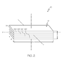
- one embodiment of the conductive fiber reinforced polymer composition may include a composite structure 12 made up of constituent materials.
- the composite structure 12 may be formed of a single ply 14 ( Fig. 1 ) or may be a laminate formed by a stacked assembly of a plurality of plies 14 ( Fig. 2 ).
- the composite structure 12 may include a length L, a width W, and a through thickness T.
- a composite structure 12 having a single composite ply 14 may include a longitudinal axis X (i.e., length), a lateral axis Y (i.e. width), and a through axis Z (i.e., through thickness).
- a composite structure 12 having a laminated stack of plies 14 may also include a longitudinal axis X, a lateral axis Y, and a through axis Z. It can be appreciated by one skilled in the art that the physical dimensions of the length L, width W, and through thickness T may vary depending upon final design and use criteria.
- each ply 14 of the composite structure 12 may include a polymer matrix 16, a reinforcing material 18, and conductive filler 20. Additional constituents may be included without departing from the scope of the present disclosure.
- the polymer matrix 16 may be a polymeric material selected from the group consisting of polyethersulfones, polyolefins, polyalkenes, polyamides, polypropylenes, polyaryletherketones, and polyphthalamides and combinations thereof.
- the polymer matrix 16 may be an epoxy resin, a vinylester or polyester thermosetting plastic resin, or phenol formaldehyde resin.
- the use of thermoplastics is also encompassed by the present disclosure.
- the molecular weight and relative viscosity of the polymer matrix 16 may incorporate a range suitable for stabilization of the reinforcement elements and the conductive fillers. In one implementation, the relative viscosity may be 1.0. In another implementation, the relative viscosity may be 2.0. In another implementation, the relative viscosity may be greater than 2.0 to provide suitable mechanical strength.
- the polymer matrix 16 may have a predetermined resistivity.
- the reinforcing material 18 may be a short fiber-reinforced material or a continuous fiber-reinforced material.
- the reinforcing material 18 may include a plurality of reinforcing fibers 22.
- the fibers 22 may be selected from the group consisting of glass (e.g., fiberglass), carbon (e.g., carbon fiber; carbon nanotubes), and polymers including the polyaramids and combinations thereof.
- the fibers 22 may be continuously aligned or randomly aligned.
- the reinforcing material 18 may include a reinforcing tape having a plurality (e.g., thousands) of fibers 22.
- the reinforcing tape may be unidirectional and may be woven, knit, braided or stitched tape.
- the reinforcing material 18 may be a hybrid that includes both reinforcing fibers 22 and reinforcing tape.
- the fibers 22 may have various lengths and diameters.
- a single ply 14 may include fibers 22 oriented in a single direction (i.e., unidirectional) or in two directions (i.e., bidirectional; for example a woven fabric). As shown in Figs. 6 and 7 , for clarity of illustration, the fibers 22 of the single ply 14 are shown in a single direction. In a composite structure 12 having a plurality of plies 14, the direction of the fibers 22 can vary throughout the stack of plurality of plies 14 to give desired mechanical properties to the composite structure 12.
- the stacked composite material 12 may have any number of plies 14 layed and cured (or consolidated) in a particular designated stacking sequence.
- the reinforcement fibers 22 may run parallel (uni/longitudinal, 0°), circumferentially (bi-axial, 90°), helically (biased, ⁇ 33° to 45°) or randomly along the length of the part.
- the orientation and type of fibers 22 may also be varied, producing a virtually isotropic laminate with equal strength in all directions.
- the composite structure 12 illustrated in Fig. 2 may be a laminate having four plies (or lamina) 14A, 14B, 14C, 14D.
- the first ply 14A may have fibers 22 oriented longitudinally.
- the second ply 14B may have fibers 22 oriented forty-five degrees (45°) relative to the first ply 14A.
- the third ply 14C may have fibers 22 oriented ninety degrees (90°) relative to the first ply 14A.
- the fourth ply may have fibers 22 oriented forty-five degrees (45°) relative to the first ply 14A. It can be appreciated by one skilled in the art that while this symmetrical lay-up is typical for composite structures 12, other asymmetrical orientations may also be used.
- the conductive filler 20 may include conductive particles 24 applied to (e.g., incorporated into) the polymer matrix 16 prior to its application to the reinforcing material 18.
- the conductive particles 24 may have any shape, such as small spheres, flakes, fibers, etc.
- the conductive filler 20 may be selected from the group consisting of conductive minerals, carbonaceous materials, metals, conductive carbonaceous materials and combinations thereof.
- the conductive filler 20 may be selected from the group consisting of exfoliated montmorillonite, carbon black, metal, graphite, and carbon.
- the conductive particles 24 may be processed (milled or chopped) to produce the conductive filler 20.
- the conductive filler 20 may be evenly distributed throughout the polymer matrix 16.
- the conductive particles 24 may be evenly distributed throughout the longitudinal axis X, the lateral axis Y, and the through axis Z.
- the resulting composite structure 12 may have increased conductivity in all directions, but due to incorporation of the added conductive filler 20, conductivity along the through axis Z may be particularly enhanced.
- the polymer matrix 16 and the added conductive filler 20 may form a conductive matrix having a specific targeted volumetric resistivity.
- the conductive matrix may have a low volumetric resistivity.
- the conductive matrix may have a thermoplastic resistivity of approximately 10 4 Scm.
- the conductive matrix may have a thermoplastic resistivity of approximately 10 9 Scm.
- the conductive matrix may have a thermoplastic resistivity ranging from about 10 4 to about 10 10 Scm.
- the polymer matrix 16 may make up between 20% to 80% by weight of the composite structure 12.
- the conductive filler 20 may make up between 0.1% and 25% by weight of the composite structure 12.
- the reinforcing material 18 may make up between 10% and 80% by weight of the composite structure 12.
- the polymer matrix 16 may make up between 20% to 80% by weight of the composite structure 12.
- the conductive filler 20 may make up between 0.1% and 25% by weight of the composite structure 12.
- the reinforcing material 18 may make up between 10% and 80% by weight of the composite structure 12.
- the polymer matrix 16 may make up between 20% to 80% by weight of the composite structure 12.
- the conductive filler 20 may make up between 0.1% and 25% by weight of the composite structure 12.
- the reinforcing material 18 may make up between 10% and 80% by weight of the composite structure 12.
- the conductive matrix may also include a thermoplastic toughening agent added to the polymer matrix 16 during a compounding process, such as prior to the addition of the matrix to the reinforcing fibers.
- This toughening agent could contribute to the z-axis conductivity of the composite.
- each ply 14 may be ready-to-mold sheet of fiber reinforcing material 18 that has been pre-impregnated with resin, i.e., prepreg.
- the method 100 may begin at block 102 with the step of providing a polymer matrix (e.g., resin).
- the polymer matrix may have a predetermined resistivity.
- a conductive filler may be provided.
- the conductive filler may be mixed with the polymer matrix.
- the conductive filler may be added to the polymer matrix in any stage (e.g., a latter stage) of the compounding process.
- the conductive filler may be added halfway through a compounding extruder screw.
- Application of the conductive filler at a latter stage may allow for incorporation of the conductive particles throughout the conductive matrix without degradation of the filler or the polymer matrix. Variations to this additive process may also provide for uniformity (or non-uniformity) of conductivity throughout the thermoplastic.
- the volumetric conductivity of the conductive matrix may be precisely controlled through materials choice and formation process.
- the conductive matrix i.e., the polymer matrix and conductive filler
- the reinforcing material may be a reinforcing tape, which is coated in a bath of conductive matrix.
- excess conductive matrix may be removed.
- the conductive matrix and reinforcing material may be allowed to cure (or consolidate in the case of thermoplastic polymer matrix materials) to form a composite structure 12.
- the disclosed conductive fiber reinforced polymer composition may make use of a conductive filler applied to a polymer matrix to increase conductivity in the through axis Z of a composite structure.
- a uniformly distributed conductive filler may lead to a decrease in volumetric heating (through increased conductivity of the composite), leading to a reduction in particle ejection potential concomitant with the conductivity increase in the z and other axes.
Landscapes
- Chemical & Material Sciences (AREA)
- Engineering & Computer Science (AREA)
- Composite Materials (AREA)
- Mechanical Engineering (AREA)
- Spectroscopy & Molecular Physics (AREA)
- Dispersion Chemistry (AREA)
- Physics & Mathematics (AREA)
- Health & Medical Sciences (AREA)
- Organic Chemistry (AREA)
- Polymers & Plastics (AREA)
- Medicinal Chemistry (AREA)
- Chemical Kinetics & Catalysis (AREA)
- Materials Engineering (AREA)
- Manufacturing & Machinery (AREA)
- Compositions Of Macromolecular Compounds (AREA)
- Reinforced Plastic Materials (AREA)
Abstract
Description
- The present disclosure is generally related to fiber reinforced plastics and, more particularly, to a fiber reinforced polymer composition having an increased conductivity in directions orthogonal to the fiber plane.
- The use of fiber reinforced plastic for various applications is well known. Due to their strength and lightweight, such composites are common in the aerospace, automotive, marine, and construction industries. Currently there is limited capacity for fiber reinforced plastics to conduct current in a direction orthogonal to the linear orientation of the primary fiber reinforcement.
- Lack of sufficient conductivity, particularly in a through thickness (-z axis) direction (e.g., interplay direction) may result in large voltage potentials to build up within and on the surfaces of the fiber reinforced plastic. These voltages are relieved through energetic phenomena termed: "sparking," "edge glow" or "edge emission". This can be a significant concern, particularly in environments where fiber reinforced composites are used in flammable environments and where Federal regulations impose stringent standards on commercial aircraft. These regulations are directed toward reducing the possibility that fuel or fuel vapors in or around a fuel tank might be ignited by ignition sources such as electrical discharges or sparks. These discharges can be produced by the imposition of electrical potentials or currents, such as those generated by direct lightning strikes.
- Lack of through thickness conduction of larger currents (i.e., current density) may result in the disassociation of the conductive carbon fibers from the matrix polymer during high current conduction due to excessive heating of the carbon fibers and surrounding matrix. In addition, the volumetric conduction of current may also induce the localized heating of composite surfaces, which can result in the ejection of particles. Particles that are near an edge of the fiber reinforced plastic articles may be of particular concern.
- Standard practice could be to increase conductive filler content within the polymer matrix and on the surface of the layers of fiber reinforcement to reduce the voltage between the layers and to allow current pathways to exist in the orthogonal directions. A previous similar solution has been to incorporate metalized spheres within the polymer matrix. The metallization could be done using a conductive element, such as nickel. Such practices, however, have lacked uniformity of conduction throughout the composite structure toxicity of the metal, oxidation and sensitivity to moisture.
- Accordingly, those skilled in the art continue with research and development efforts to overcome z-direction conductivity issues in the field of fiber reinforced plastics.
- In one embodiment, the disclosed conductive fiber reinforced polymer composition may include a composite structure having a longitudinal (x) axis, a lateral (y) axis, and a through (z) axis, the composite structure including a polymer matrix, a conductive filler applied to (e.g., or incorporated into) the polymer matrix, and a reinforcing (and, optionally, conductive) material trapped by the matrix.
- In another embodiment, the disclosed conductive fiber reinforced polymer composition may include a composite structure having a longitudinal (x) axis, a lateral (y) axis, and a through (z) axis, the composite structure including a polymer matrix, at least one of a conductive mineral, a carbonaceous material, and a metal in the polymer matrix, and a fibrous reinforcing material.
- In another embodiment, disclosed is a method for forming a conductive fiber reinforced polymer, the method may include the steps of: (1) providing a polymer matrix, (2) providing a conductive filler, and (3) using the conductive filler in the polymer matrix in a compounding process to form a conductive matrix.
- In yet another embodiment, disclosed is a method for forming a conductive fiber reinforced polymer, the method may include the steps of: (1) providing a polymer matrix, (2) providing a conductive filler, (3) incorporation of the conductive filler to the polymer matrix forming a resin system of increased electrical conductivity, (4) providing a reinforcing material, and (5) applying the conductive matrix to the reinforcing material to form a composite structure.
- Other aspects of the disclosed conductive fiber reinforced polymer composition will become apparent from the following detailed description, the accompanying drawings and the appended claims.
-
-
Fig. 1 is a perspective view of an embodiment of the disclosed conductive fiber reinforced polymer composition; -
Fig. 2 is a perspective view of another embodiment of the disclosed conductive fiber reinforced polymer composition; -
Fig. 3 is a front view of the disclosed conductive fiber reinforced polymer composition ofFig. 1 ; -
Fig. 4 is a side view of the disclosed conductive fiber reinforced polymer composition ofFig. 1 ; -
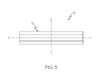
Fig. 5 is a side view of the disclosed conductive fiber reinforced polymer composition ofFig. 2 ; -
Fig. 6 is a cross sectional view of the disclosed conductive fiber reinforced polymer composition taken along section line A-A ofFig. 3 ; -
Fig. 7 is a cross sectional view of the disclosed conductive fiber reinforced polymer composition taken along section line B-B ofFig. 4 ; and, -
Fig. 8 is a flow chart illustrating an embodiment of the disclosed method of making a conductive fiber reinforced polymer composition. - The following detailed description refers to the accompanying drawings, which illustrate specific embodiments of the disclosure. Other embodiments having different structures and operations do not depart from the scope of the present disclosure. Like reference numerals may refer to the same element or component in the different drawings.
- Referring to
Figs. 1 and2 , one embodiment of the conductive fiber reinforced polymer composition, generally designated 10, may include acomposite structure 12 made up of constituent materials. Thecomposite structure 12 may be formed of a single ply 14 (Fig. 1 ) or may be a laminate formed by a stacked assembly of a plurality of plies 14 (Fig. 2 ). Thecomposite structure 12 may include a length L, a width W, and a through thickness T. - Referring to
Figs. 3-5 , acomposite structure 12 having a singlecomposite ply 14 may include a longitudinal axis X (i.e., length), a lateral axis Y (i.e. width), and a through axis Z (i.e., through thickness). Correspondingly, acomposite structure 12 having a laminated stack ofplies 14 may also include a longitudinal axis X, a lateral axis Y, and a through axis Z. It can be appreciated by one skilled in the art that the physical dimensions of the length L, width W, and through thickness T may vary depending upon final design and use criteria. - Referring to
Figs. 6 and 7 , the constituent materials of eachply 14 of thecomposite structure 12 may include apolymer matrix 16, a reinforcingmaterial 18, andconductive filler 20. Additional constituents may be included without departing from the scope of the present disclosure. - The
polymer matrix 16 may be a polymeric material selected from the group consisting of polyethersulfones, polyolefins, polyalkenes, polyamides, polypropylenes, polyaryletherketones, and polyphthalamides and combinations thereof. For example, thepolymer matrix 16 may be an epoxy resin, a vinylester or polyester thermosetting plastic resin, or phenol formaldehyde resin. The use of thermoplastics is also encompassed by the present disclosure. The molecular weight and relative viscosity of thepolymer matrix 16 may incorporate a range suitable for stabilization of the reinforcement elements and the conductive fillers. In one implementation, the relative viscosity may be 1.0. In another implementation, the relative viscosity may be 2.0. In another implementation, the relative viscosity may be greater than 2.0 to provide suitable mechanical strength. Thepolymer matrix 16 may have a predetermined resistivity. - The reinforcing
material 18 may be a short fiber-reinforced material or a continuous fiber-reinforced material. In one implementation, thereinforcing material 18 may include a plurality of reinforcingfibers 22. Thefibers 22 may be selected from the group consisting of glass (e.g., fiberglass), carbon (e.g., carbon fiber; carbon nanotubes), and polymers including the polyaramids and combinations thereof. Thefibers 22 may be continuously aligned or randomly aligned. In another implementation, the reinforcingmaterial 18 may include a reinforcing tape having a plurality (e.g., thousands) offibers 22. The reinforcing tape may be unidirectional and may be woven, knit, braided or stitched tape. In another implementation, the reinforcingmaterial 18 may be a hybrid that includes both reinforcingfibers 22 and reinforcing tape. Thefibers 22 may have various lengths and diameters. - A
single ply 14 may includefibers 22 oriented in a single direction (i.e., unidirectional) or in two directions (i.e., bidirectional; for example a woven fabric). As shown inFigs. 6 and 7 , for clarity of illustration, thefibers 22 of thesingle ply 14 are shown in a single direction. In acomposite structure 12 having a plurality ofplies 14, the direction of thefibers 22 can vary throughout the stack of plurality ofplies 14 to give desired mechanical properties to thecomposite structure 12. The stackedcomposite material 12 may have any number ofplies 14 layed and cured (or consolidated) in a particular designated stacking sequence. - The
reinforcement fibers 22 may run parallel (uni/longitudinal, 0°), circumferentially (bi-axial, 90°), helically (biased, ±33° to 45°) or randomly along the length of the part. The orientation and type offibers 22 may also be varied, producing a virtually isotropic laminate with equal strength in all directions. For example, thecomposite structure 12 illustrated inFig. 2 may be a laminate having four plies (or lamina) 14A, 14B, 14C, 14D. Thefirst ply 14A may havefibers 22 oriented longitudinally. Thesecond ply 14B may havefibers 22 oriented forty-five degrees (45°) relative to thefirst ply 14A. Thethird ply 14C may havefibers 22 oriented ninety degrees (90°) relative to thefirst ply 14A. The fourth ply may havefibers 22 oriented forty-five degrees (45°) relative to thefirst ply 14A. It can be appreciated by one skilled in the art that while this symmetrical lay-up is typical forcomposite structures 12, other asymmetrical orientations may also be used. - The
conductive filler 20 may includeconductive particles 24 applied to (e.g., incorporated into) thepolymer matrix 16 prior to its application to the reinforcingmaterial 18. Theconductive particles 24 may have any shape, such as small spheres, flakes, fibers, etc. In one expression, theconductive filler 20 may be selected from the group consisting of conductive minerals, carbonaceous materials, metals, conductive carbonaceous materials and combinations thereof. In another expression, theconductive filler 20 may be selected from the group consisting of exfoliated montmorillonite, carbon black, metal, graphite, and carbon. Theconductive particles 24 may be processed (milled or chopped) to produce theconductive filler 20. Theconductive filler 20 may be evenly distributed throughout thepolymer matrix 16. For example, as illustrated inFigs. 6 and 7 , theconductive particles 24 may be evenly distributed throughout the longitudinal axis X, the lateral axis Y, and the through axis Z. The resultingcomposite structure 12 may have increased conductivity in all directions, but due to incorporation of the addedconductive filler 20, conductivity along the through axis Z may be particularly enhanced. - When combined, the
polymer matrix 16 and the addedconductive filler 20 may form a conductive matrix having a specific targeted volumetric resistivity. For example, the conductive matrix may have a low volumetric resistivity. As one specific example, the conductive matrix may have a thermoplastic resistivity of approximately 104 Scm. As another specific example, the conductive matrix may have a thermoplastic resistivity of approximately 109 Scm. As yet another specific example, the conductive matrix may have a thermoplastic resistivity ranging from about 104 to about 1010 Scm. - In one construction, the
polymer matrix 16 may make up between 20% to 80% by weight of thecomposite structure 12. Theconductive filler 20 may make up between 0.1% and 25% by weight of thecomposite structure 12. The reinforcingmaterial 18 may make up between 10% and 80% by weight of thecomposite structure 12. In another construction, thepolymer matrix 16 may make up between 20% to 80% by weight of thecomposite structure 12. Theconductive filler 20 may make up between 0.1% and 25% by weight of thecomposite structure 12. The reinforcingmaterial 18 may make up between 10% and 80% by weight of thecomposite structure 12. In yet another construction, thepolymer matrix 16 may make up between 20% to 80% by weight of thecomposite structure 12. Theconductive filler 20 may make up between 0.1% and 25% by weight of thecomposite structure 12. The reinforcingmaterial 18 may make up between 10% and 80% by weight of thecomposite structure 12. - Optionally, the conductive matrix may also include a thermoplastic toughening agent added to the
polymer matrix 16 during a compounding process, such as prior to the addition of the matrix to the reinforcing fibers. This toughening agent could contribute to the z-axis conductivity of the composite. - The
composite structure 12 may be formed using any suitable manufacturing technique, including wet lay-up, spray-up, compression, injection, resin transfer, vacuum assisted resin infusion, or similar methods. Alternatively, each ply 14 may be ready-to-mold sheet offiber reinforcing material 18 that has been pre-impregnated with resin, i.e., prepreg. - Referring to
Fig. 8 , also disclosed is a method, generally designed 100, for making a conductive fiber reinforced polymer composition. Themethod 100 may begin atblock 102 with the step of providing a polymer matrix (e.g., resin). The polymer matrix may have a predetermined resistivity. - As shown at block 104, a conductive filler may be provided. As shown in
block 106, the conductive filler may be mixed with the polymer matrix. The conductive filler may be added to the polymer matrix in any stage (e.g., a latter stage) of the compounding process. For example, the conductive filler may be added halfway through a compounding extruder screw. Application of the conductive filler at a latter stage may allow for incorporation of the conductive particles throughout the conductive matrix without degradation of the filler or the polymer matrix. Variations to this additive process may also provide for uniformity (or non-uniformity) of conductivity throughout the thermoplastic. The volumetric conductivity of the conductive matrix may be precisely controlled through materials choice and formation process. - As shown at
block 108, the conductive matrix (i.e., the polymer matrix and conductive filler) may be applied to the reinforcing material to form the composite structure. For example, the reinforcing material may be a reinforcing tape, which is coated in a bath of conductive matrix. As shown atblock 110, excess conductive matrix may be removed. As shown atblock 112, the conductive matrix and reinforcing material may be allowed to cure (or consolidate in the case of thermoplastic polymer matrix materials) to form acomposite structure 12. - Accordingly, the disclosed conductive fiber reinforced polymer composition may make use of a conductive filler applied to a polymer matrix to increase conductivity in the through axis Z of a composite structure. A uniformly distributed conductive filler may lead to a decrease in volumetric heating (through increased conductivity of the composite), leading to a reduction in particle ejection potential concomitant with the conductivity increase in the z and other axes.
- Although various aspects of the disclosed conductive fiber reinforced polymer composition have been shown and described, modifications may occur to those skilled in the art upon reading the present disclosure. The present application includes such modifications and is limited only by the scope of the claims.
Claims (17)
- A conductive fiber reinforced polymer composition comprising:a composite structure comprising a longitudinal axis, a lateral axis, and a through axis, said composite structure comprising:a polymer matrix;a conductive filler in said polymer matrix; anda reinforcing material in said polymer matrix.
- The composition of Claim 1 wherein said conductive filler comprises a material selected from a group consisting of conductive minerals, carbonaceous materials, metals, and combinations thereof.
- The composition of Claim 1 wherein said reinforcing material comprises a material selected from a group consisting of glass, fiberglass, carbon fiber, polyaramid, carbon nanotubes and combinations thereof.
- The composition of Claim 3 wherein said reinforcing material comprises a plurality of reinforcing fibers.
- The composition of Claim 3 wherein said reinforcing material comprises a reinforcing fiber tape.
- The composition of Claim 1 wherein said polymer matrix comprises a material selected from a group consisting of polyethersulfones, polyolefins, polyalkenes, polyamides, polypropylenes, polyaryletherketones, polyphthalamides, and combinations thereof.
- The composition of Claim 1 wherein said composite structure comprises a composite ply.
- The composition of Claim 1 wherein said composite structure comprises a laminated stack of a plurality of composite plies.
- The composition of Claim 1 wherein said reinforcing material is aligned along a plane substantially parallel to said longitudinal axis.
- The composition of Claim 1 wherein said reinforcing material is aligned along a plane substantially parallel to said lateral axis.
- The composition of Claim 1 further comprising a thermoplastic toughening agent.
- The composition of Claim 1 wherein said conductive filler comprises low volumetric resistivity.
- A method of forming a conductive fiber reinforced polymer, said method comprising the steps of:providing a polymer matrix;providing a conductive filler; andintroducing said conductive filler to said polymer matrix in a compounding process to form a conductive matrix.
- The method of Claim 13 further comprising the steps of:providing a reinforcing material; andapplying said conductive matrix to said reinforcing material to form a composite structure.
- The method of Claim 14 wherein said composite structure comprises low volumetric resistivity for directions orthogonal to said reinforcing material.
- The method of Claim 13 wherein said conductive filler is introduced to said polymer matrix in a latter stage of said compounding process.
- The method of Claim 13 wherein said conductive filler comprises a material selected from a group consisting of conductive minerals, carbonaceous materials, metals, and combinations thereof.
Applications Claiming Priority (1)
| Application Number | Priority Date | Filing Date | Title |
|---|---|---|---|
| US13/751,800 US10102939B2 (en) | 2013-01-28 | 2013-01-28 | Conductive fiber reinforced polymer composition |
Publications (2)
| Publication Number | Publication Date |
|---|---|
| EP2759563A2 true EP2759563A2 (en) | 2014-07-30 |
| EP2759563A3 EP2759563A3 (en) | 2014-08-27 |
Family
ID=49816846
Family Applications (1)
| Application Number | Title | Priority Date | Filing Date |
|---|---|---|---|
| EP20130197580 Withdrawn EP2759563A3 (en) | 2013-01-28 | 2013-12-17 | Conductive fiber reinforced polymer composition |
Country Status (3)
| Country | Link |
|---|---|
| US (1) | US10102939B2 (en) |
| EP (1) | EP2759563A3 (en) |
| JP (1) | JP6611413B2 (en) |
Cited By (4)
| Publication number | Priority date | Publication date | Assignee | Title |
|---|---|---|---|---|
| EP2687557A4 (en) * | 2011-03-17 | 2014-12-03 | Toray Industries | Prepreg, method of manufacturing prepreg, and carbon fiber-reinforced composite material |
| US20160347918A1 (en) * | 2015-05-26 | 2016-12-01 | The Boeing Company | Enhancing Z-Conductivity in Carbon Fiber Reinforced Plastic Composite Layups |
| US9994371B2 (en) | 2014-07-22 | 2018-06-12 | Entegris, Inc. | Molded fluoropolymer breakseal with compliant material |
| EP3617280A1 (en) * | 2018-08-29 | 2020-03-04 | The Boeing Company | Integrated surface protection system, composite structure, and method for protecting the same |
Families Citing this family (1)
| Publication number | Priority date | Publication date | Assignee | Title |
|---|---|---|---|---|
| JP6580359B2 (en) | 2015-03-31 | 2019-09-25 | 三菱重工業株式会社 | Structure manufacturing method and structure |
Family Cites Families (20)
| Publication number | Priority date | Publication date | Assignee | Title |
|---|---|---|---|---|
| JPS5137223B2 (en) | 1974-05-14 | 1976-10-14 | ||
| US4272346A (en) | 1979-12-03 | 1981-06-09 | Washington State University Research Foundation | Treatment of carbon fibers to decrease electrical hazards of conductive fiber fragment release |
| JPS5853111A (en) * | 1981-09-24 | 1983-03-29 | 太平洋工業株式会社 | Conductive composite material |
| JPH0748461A (en) | 1993-08-05 | 1995-02-21 | Kobe Steel Ltd | Fiber-reinforced composite resin for fixed pallet and production thereof |
| JPH10158443A (en) | 1996-12-05 | 1998-06-16 | Idemitsu N S G Kk | Stampable sheet with excellent conductivity and mechanical strength |
| US6934600B2 (en) * | 2002-03-14 | 2005-08-23 | Auburn University | Nanotube fiber reinforced composite materials and method of producing fiber reinforced composites |
| US7935415B1 (en) * | 2002-04-17 | 2011-05-03 | Conductive Composites Company, L.L.C. | Electrically conductive composite material |
| JP2004051852A (en) * | 2002-07-22 | 2004-02-19 | Polymatech Co Ltd | Thermally conductive polymer molding and its production method |
| JP4111506B2 (en) * | 2003-04-11 | 2008-07-02 | ニチアス株式会社 | Conductive resin composition, fuel cell separator and method for producing the same |
| JP4686274B2 (en) * | 2005-06-30 | 2011-05-25 | ポリマテック株式会社 | Heat dissipation component and manufacturing method thereof |
| JP4969363B2 (en) | 2006-08-07 | 2012-07-04 | 東レ株式会社 | Prepreg and carbon fiber reinforced composites |
| GB0622060D0 (en) * | 2006-11-06 | 2006-12-13 | Hexcel Composites Ltd | Improved composite materials |
| US7599164B2 (en) | 2006-12-07 | 2009-10-06 | The Boeing Company | Lightning protection system for aircraft composite structure |
| JP4951478B2 (en) | 2007-12-03 | 2012-06-13 | 三菱レイヨン株式会社 | Method for producing carbon nanotube-containing matrix resin |
| GB0805640D0 (en) * | 2008-03-28 | 2008-04-30 | Hexcel Composites Ltd | Improved composite materials |
| KR101834288B1 (en) * | 2008-08-18 | 2018-03-06 | 프로덕티브 리서치 엘엘씨 | Formable light weight composites |
| US8524120B2 (en) | 2009-06-19 | 2013-09-03 | Sabic Innovative Plastics Ip B.V. | Single conductive pellets of long glass fiber reinforced thermoplastic resin and manufacturing method thereof |
| US8791375B2 (en) | 2010-12-16 | 2014-07-29 | The Boeing Company | Electrically conductive bushing connection to structure for current path |
| US20120282453A1 (en) | 2011-05-05 | 2012-11-08 | North Carolina State University | Carbon nanotube composites and methods and apparatus for fabricating same |
| US10046528B2 (en) * | 2012-02-20 | 2018-08-14 | The Boeing Company | Composite layers with exposed reinforcement |
-
2013
- 2013-01-28 US US13/751,800 patent/US10102939B2/en active Active
- 2013-12-17 EP EP20130197580 patent/EP2759563A3/en not_active Withdrawn
-
2014
- 2014-01-23 JP JP2014010236A patent/JP6611413B2/en active Active
Non-Patent Citations (1)
| Title |
|---|
| None |
Cited By (9)
| Publication number | Priority date | Publication date | Assignee | Title |
|---|---|---|---|---|
| EP2687557A4 (en) * | 2011-03-17 | 2014-12-03 | Toray Industries | Prepreg, method of manufacturing prepreg, and carbon fiber-reinforced composite material |
| US9994371B2 (en) | 2014-07-22 | 2018-06-12 | Entegris, Inc. | Molded fluoropolymer breakseal with compliant material |
| US20160347918A1 (en) * | 2015-05-26 | 2016-12-01 | The Boeing Company | Enhancing Z-Conductivity in Carbon Fiber Reinforced Plastic Composite Layups |
| EP3106291A3 (en) * | 2015-05-26 | 2017-03-08 | The Boeing Company | Enhancing z-conductivity in carbon fiber reinforced plastic composite layups |
| US10472473B2 (en) | 2015-05-26 | 2019-11-12 | The Boeing Company | Enhancing z-conductivity in carbon fiber reinforced plastic composite layups |
| EP3617280A1 (en) * | 2018-08-29 | 2020-03-04 | The Boeing Company | Integrated surface protection system, composite structure, and method for protecting the same |
| CN110871614A (en) * | 2018-08-29 | 2020-03-10 | 波音公司 | Integrated surface protection system and method of protecting composite structures |
| US11220351B2 (en) | 2018-08-29 | 2022-01-11 | The Boeing Company | Integrated surface protection system, composite structure, and method for protecting the same |
| CN110871614B (en) * | 2018-08-29 | 2024-07-19 | 波音公司 | Integrated surface protection system and method for protecting composite structures |
Also Published As
| Publication number | Publication date |
|---|---|
| JP2014145075A (en) | 2014-08-14 |
| EP2759563A3 (en) | 2014-08-27 |
| US10102939B2 (en) | 2018-10-16 |
| US20140212620A1 (en) | 2014-07-31 |
| JP6611413B2 (en) | 2019-11-27 |
Similar Documents
| Publication | Publication Date | Title |
|---|---|---|
| US10102939B2 (en) | Conductive fiber reinforced polymer composition | |
| Guo et al. | Simultaneously increasing the electrical conductivity and fracture toughness of carbon–fiber composites by using silver nanowires-loaded interleaves | |
| CN103144385B (en) | The composite improved | |
| CA3095453C (en) | Electrically conductive adhesive | |
| CN108431098B (en) | Structural body | |
| CN108431099B (en) | structure | |
| US10059080B2 (en) | Method for the production of a fiber composite component, and semifinished textile product therefor | |
| WO2015130368A3 (en) | Composite materials with electrically conductive and delamination resistant properties | |
| Li et al. | Simultaneous enhancement of electrical conductivity and interlaminar fracture toughness of carbon fiber/epoxy composites using plasma-treated conductive thermoplastic film interleaves | |
| US10882224B2 (en) | Method for manufacturing structure material | |
| WO2013032620A1 (en) | Interlaminar toughening of thermoplastics | |
| WO2020040287A1 (en) | Carbon fiber sheet material, prepreg, molded article, carbon fiber sheet material production method, prepreg production method, and molded article production method | |
| EP3447083B1 (en) | Carbon nanotube enhanced polymers and methods for manufacturing the same | |
| KR101923381B1 (en) | Composite material for reinforcement and articles comprising the same | |
| Erkmen et al. | Improvement in mechanical, electrical, and shape memory properties of the polystyrene‐based carbon fiber‐reinforced polymer composites containing carbon nanotubes | |
| Sarr et al. | Effect of cellulose nanofibers on the fracture toughness mode II of glass fiber/epoxy composite laminates | |
| Luo et al. | Ordered Alignment of Short Carbon Fibers Enabling High‐Performance Carbon Fiber/Epoxy Resin Composites With Synergistic Thermal Conductive and Mechanical Enhancement | |
| Kumar et al. | Focus on carbon fiber reinforced composites manufacturing and properties | |
| DE102007057491A1 (en) | Component useful in air- and space-craft vehicles, has resin matrix in which carbon nanotubes are embedded for high conductivity of component, and internal layer, at which external layer adjoins and which is made of fiber composite material | |
| CA2916498A1 (en) | Dissipation of static electricity | |
| CN110343363B (en) | Conductive carbon fiber composite material and preparation method thereof | |
| KR20150069163A (en) | A method of preparing thermoplastic prepreg | |
| US10759140B1 (en) | Composite damage tolerance and through thickness conductivity by interleaving carbon fiber veil nanocomposites | |
| KR20120024271A (en) | The lightweight complexmaterial for emi shielding | |
| Mahato et al. | A review of electrospun nanofiber interleaves for interlaminar toughening of composite laminates. Polymers 2023; 15: 1380 |
Legal Events
| Date | Code | Title | Description |
|---|---|---|---|
| PUAL | Search report despatched |
Free format text: ORIGINAL CODE: 0009013 |
|
| PUAI | Public reference made under article 153(3) epc to a published international application that has entered the european phase |
Free format text: ORIGINAL CODE: 0009012 |
|
| 17P | Request for examination filed |
Effective date: 20131217 |
|
| AK | Designated contracting states |
Kind code of ref document: A2 Designated state(s): AL AT BE BG CH CY CZ DE DK EE ES FI FR GB GR HR HU IE IS IT LI LT LU LV MC MK MT NL NO PL PT RO RS SE SI SK SM TR |
|
| AX | Request for extension of the european patent |
Extension state: BA ME |
|
| AK | Designated contracting states |
Kind code of ref document: A3 Designated state(s): AL AT BE BG CH CY CZ DE DK EE ES FI FR GB GR HR HU IE IS IT LI LT LU LV MC MK MT NL NO PL PT RO RS SE SI SK SM TR |
|
| AX | Request for extension of the european patent |
Extension state: BA ME |
|
| RIC1 | Information provided on ipc code assigned before grant |
Ipc: B29C 70/88 20060101ALI20140718BHEP Ipc: C08J 5/10 20060101AFI20140718BHEP |
|
| R17P | Request for examination filed (corrected) |
Effective date: 20150218 |
|
| RBV | Designated contracting states (corrected) |
Designated state(s): AL AT BE BG CH CY CZ DE DK EE ES FI FR GB GR HR HU IE IS IT LI LT LU LV MC MK MT NL NO PL PT RO RS SE SI SK SM TR |
|
| STAA | Information on the status of an ep patent application or granted ep patent |
Free format text: STATUS: EXAMINATION IS IN PROGRESS |
|
| 17Q | First examination report despatched |
Effective date: 20170616 |
|
| RAP3 | Party data changed (applicant data changed or rights of an application transferred) |
Owner name: THE BOEING COMPANY |
|
| STAA | Information on the status of an ep patent application or granted ep patent |
Free format text: STATUS: THE APPLICATION HAS BEEN WITHDRAWN |
|
| 18W | Application withdrawn |
Effective date: 20240410 |