EP2759466A1 - Tie down assembly - Google Patents
Tie down assembly Download PDFInfo
- Publication number
- EP2759466A1 EP2759466A1 EP14154442.9A EP14154442A EP2759466A1 EP 2759466 A1 EP2759466 A1 EP 2759466A1 EP 14154442 A EP14154442 A EP 14154442A EP 2759466 A1 EP2759466 A1 EP 2759466A1
- Authority
- EP
- European Patent Office
- Prior art keywords
- cup
- crossbar
- tie down
- down assembly
- fasteners
- Prior art date
- Legal status (The legal status is an assumption and is not a legal conclusion. Google has not performed a legal analysis and makes no representation as to the accuracy of the status listed.)
- Granted
Links
Images












Classifications
-
- B—PERFORMING OPERATIONS; TRANSPORTING
- B60—VEHICLES IN GENERAL
- B60P—VEHICLES ADAPTED FOR LOAD TRANSPORTATION OR TO TRANSPORT, TO CARRY, OR TO COMPRISE SPECIAL LOADS OR OBJECTS
- B60P7/00—Securing or covering of load on vehicles
- B60P7/06—Securing of load
- B60P7/08—Securing to the vehicle floor or sides
- B60P7/0807—Attachment points
-
- B—PERFORMING OPERATIONS; TRANSPORTING
- B63—SHIPS OR OTHER WATERBORNE VESSELS; RELATED EQUIPMENT
- B63B—SHIPS OR OTHER WATERBORNE VESSELS; EQUIPMENT FOR SHIPPING
- B63B25/00—Load-accommodating arrangements, e.g. stowing, trimming; Vessels characterised thereby
- B63B25/24—Means for preventing unwanted cargo movement, e.g. dunnage
Definitions
- the present invention relates to a tie down assembly and, more particularly, to a tie down assembly for naval and maritime vessels.
- Tie down assemblies are commonplace on naval and maritime vessels, as they facilitate the security of cargo, containers, vehicles (such as aircraft, tanks and trucks), and other heavy items and equipment. Tie down assemblies are typically installed within a deck of the vessel. Tie down assemblies must be sufficiently secured within the deck and be strong enough to endure heavy loads. In addition, it is desirable for tie down assemblies to be easily repaired and replaced within the deck.
- a tie down assembly adapted to be installed within a structure includes a cup and a crossbar that is fastened removably to the cup by a plurality of fasteners.
- the cup includes a first end, a second end opposite the first end, a recess formed within the first end and defining an interior surface and an inner wall surrounding the interior surface, and a plurality of seats extending from the interior surface.
- each of the plurality of seats includes a bore.
- the crossbar includes a central portion and a plurality of members extending from the central portion.
- each of the plurality of members includes a free end having a head and an aperture formed within the head.
- the crossbar is positioned within the recess of the cup and each of the heads of the plurality of members of the crossbar engages a corresponding one of the plurality of seats of the cup.
- each of the apertures of the heads of the crossbar aligns with a corresponding one of the bores of the plurality of seats of the cup.
- each of the aligned apertures receive a corresponding one of the plurality of fasteners.
- the cup includes a plurality of pockets formed within the inner wall of the cup, and each of the plurality of seats of the cup is positioned within a corresponding one of the plurality of pockets of the cup.
- each of the plurality of pockets of the cup includes a pair of sidewalls, each of the heads of the plurality of members of the crossbar being positioned between a corresponding one of the pair of sidewalls.
- the sidewalls act as stops that inhibit rotation of the crossbar relative to the cup when a load is applied to the crossbar.
- the crossbar is adapted to receive tie down hooks, connectors, and the like. In an embodiment, when the crossbar requires repair or replacement, it may be removed from the cup by unfastening the fasteners without the need to remove the cup from the structure.
- the cup is made from aluminum, while the crossbar is made from steel.
- the structure is an aluminum deck of a vessel.
- a tie down assembly 10 includes a cylindrical-shaped cup 12 and a cross-shaped crossbar 14 that is fastened removably to the cup 12 by a plurality of fasteners 16.
- the cup 12 is made from aluminum and the crossbar 14 is made from steel.
- the cup 12 is made from an aluminum-magnesium-silicon alloy (6xxxx series alloy), an aluminum-magnesium alloy (5xxxx series alloy), or another marine specified aluminum alloy.
- the crossbar 14 is made from 4130 steel. In other embodiments, the crossbar 14 is made from other marine specified steel, aluminum, or titanium.
- the cup 12 and the crossbar 14 are made from other suitable materials known in the art, such as other types of metals or metal alloys.
- the cup 12 and the crossbar 14 are produced by forging.
- the cup 12 is produced by machining.
- the crossbar 14 is produced by machining, or by forging and machining. While the cup 12 is cylindrical-shaped, it may consist of other shapes and sizes, in accordance with other embodiments. While the crossbar 14 is cross-shaped, it may consist of other shapes and sizes, in accordance with other embodiments. The features and functions of the cup 12 and the crossbar 14 shall be described hereinafter.
- the cup 12 includes an upper end 18 and a lower end 20 that is opposite the upper end 18, and a ring-shaped sidewall 22 that extends from the upper end 18 to the lower end 20.
- the cup 12 includes a recess 24 that extends from the upper end 18 and is defined by a concave interior surface 26.
- a plurality of pockets 28 are formed on the interior surface 26 of the cup 12.
- Each of the pockets 28 includes a seat 30 and a pair of opposed angular walls 32a, 32b that extend upwardly from the interior surface 26 of the cup 12 to the upper end 18 of the cup 12 and flank the seat 30.
- Each of the pockets 28 includes a counter bore 34 that is formed within the corresponding seat 30 and extends towards the lower end 20 of the cup 12.
- Each of the counter bores 34 is sized and shaped to receive a corresponding one of the fasteners 16, which will be described in more detail below.
- each of the counter bores 34 includes internal threads (not shown in the Figures).
- the cup 12 includes four of the pockets 28, which are arranged in a cross-like pattern (i.e., positioned 90 degrees from each other) on the interior surface 26 of the cup 12. In other embodiments, the cup 12 may include more or less than four of the pockets 28.
- a lower, exterior surface 36 of the cup 12 includes a plurality of ribs 38 extending therefrom and from the lower end 20 of the cup 12 to a central portion 40, and are separated from one another by a plurality of gaps 42.
- the ribs 38 provide for strength and stiffness, while the gaps 42 result in mass reduction of the tie down assembly 10.
- the ribs 38 are arranged in a cross-like pattern (i.e., positioned 90 degrees from each other) on the exterior surface 36.
- the cup 12 may include more or less than four of the ribs 38.
- the crossbar 14 includes a plurality of tubular-shaped members 44, each of which has a first end 46 that intersects with the other first ends 46 at a central point 48, and a free end 50 opposite the first end 46. In an embodiment, all of the members 44 lie within the same plane. In an embodiment, the crossbar 14 includes four of the members 44. In other embodiments, the crossbar 14 includes more or less than four of the members 44. In an embodiment, each of the members 44 includes a hexagonal-shaped head 52 formed at the free end 50 thereof and a centrally located, circular-shaped aperture 54 extending through the head 52. In other embodiments, each of the heads 52 consists of different shapes and sizes, such as square-shaped, circular-shaped, etc.
- the crossbar 14 is fastened to the cup 12 by the fasteners 16.
- the crossbar 14 is positioned within the recess 24 of the cup 12, such that one of heads 52 of the crossbar 14 is positioned within a corresponding one of the pockets 28 of the cup 12.
- one of the apertures 54 of the members 44 of the crossbar 14 aligns with a corresponding one of the counter bores 34 of the cup 12.
- Each of the fasteners 16 threadedly engages a corresponding one of the counter bores 34 of the cup 12, thereby securing the crossbar 14 to the cup 12.
- the fasteners 16 include uncoated, high strength bolts made from corrosion resistant materials, such as Monel or stainless steel.
- the fasteners 16 include anti-corrosion, coated steel threaded bolts, such as GEOMET® bolts manufactured by Metal Coatings International Inc.
- the fasteners 16 include self-sealing bolts having embedded O-rings.
- the fasteners 16 include bolts separated from the O-rings and assembled together.
- O-rings are positioned within grooves formed within the seats 30 of the pockets 28 (not shown in FIGS. 2A through 2E ) in order to provide water tight seals and corrosion resistance between the pockets 28 and the heads 52 of the crossbar 14.
- the O-rings are made from VITON® brand of synthetic rubber or fluropolymer elastomer, made by DuPont Performance Elastomers LLC.
- the counter bores 34 are applied with a water repellent sealant (not shown in the Figures).
- the sealant is SIKAFLEX® 221 adhesive sealant.
- each of the counter bores 34 is sized and shaped to include threaded inserts (not shown in FIGS. 1A through 2E ) that threadedly engage a corresponding one of the fasteners 16.
- the threaded inserts are RECOIL® brand of inserts manufactured by Alcoa Fastening Systems, but other brands of inserts may be utilized.
- the tie down assembly 10 is installed within a deck 58 of a vessel having an exterior surface 60 and an interior surface 62.
- the deck 58 is made from aluminum. In other embodiments, the deck 58 is made from other materials, such as metals and metal alloys.
- the deck 58 includes a solid portion(s). In another embodiment, the deck 58 is corrugated (not shown in the Figures). In another embodiment, the deck 58 is a multi-hollow extrusion (not shown in the Figures). In another embodiment, the deck 58 is characterized by complex structural geometry (not shown in the Figures).
- the tie down assembly 10 To install the tie down assembly 10, a hole is bored in the deck 58 from the exterior surface 60 to the interior surface 62 (not shown in the Figures). The diameter of the hole is substantially equal to the diameter of the sidewall 22 of the cup 12. Next, the tie down assembly 10 is positioned within the hole. In an embodiment, the radial clearance between the sidewall 22 of the cup 12 and the hole of the deck 58 is about 0.0197 inches ⁇ 0.004 inches (0.5 mm ⁇ 0.1 mm).
- the upper end 18 of the cup 12 protrudes above the exterior surface 60 of the deck 58, while the lower end 20 of the cup 12 protrudes below the interior surface 62 of the deck 58, leaving the crossbar 14 and the recess 24 of the cup 12 exposed within the exterior surface 60 of the deck 58.
- the upper end 18 of the cup 12 lies flush with the exterior surface 60 of the deck 58, while the lower end 20 of the cup 12 lies flush with the interior surface 62 of the deck 58.
- the upper end 18 of the cup 12 is welded to the exterior surface 60 of the deck 58, while the lower end 20 of the cup 12 is welded to the interior surface 62 of the deck 58.
- the crossbar 14 is sized and shaped to accommodate the receipt of various tie down connectors, such as hooks, clips, cables, rope, etc. (not shown in the Figures).
- the crossbar 14 provides uniform load distribution for the tie down assembly 10. In this regard, there are tight radial fits between the heads 52 of the crossbar 14 and the pockets 28 of the cup 12 to react against shear loads.
- the walls of the pockets 28 prevent rotation of the crossbar 14 relative to the cup 12, especially during lashing, which react against torques and shear loads imparted on the crossbar 14.
- the crossbar 14 reacts against axial loads as well, which are borne by the fasteners 16.
- the crossbar 14 In the event that the crossbar 14 requires, inspection, repair or replacement, it is easily removed from the deck 58 by removing the fasteners 16 from the crossbar 14 and the cup 12 using standard tools ⁇ e.g., socket wrenches, etc.). As a result, the crossbar 14 is easily lifted out of the cup 12, while the cup 12 remains secured to the deck 58. Consequently, the entire tie down assembly 10 need not be removed or cut out to inspect, repair or replace the crossbar 14.
- the cup 12 is made from aluminum, while the crossbar 14 is made from steel, as mentioned above.
- the tie down assembly 10 utilizes the advantages of both aluminum and steel.
- the cup 12 is lightweight (e.g., approximately 50% weight savings), corrosion resistant, and allows for the tie down assembly 10 to be installed into the aluminum deck 58 without the need for costly and lengthy manufacturing and installation processes.
- the tie down assembly 10 does not require any changes in a shipbuilder's manufacturing process, while at the same time offers the advantages of being lightweight and allowing easy replacement and inspection of the assembly 10. Lower weight savings also translates into lower fuel consumption over the lifetime of the vessel.
- the steel crossbar 14 maintains high strength, especially during lashing.
- the tie down assembly 10 requires minimal assembly time and skill to install, thereby reducing installation costs. Last but not least, the tie down assembly 10 is compact and requires less space to install.
- the crossbar 14 may be coated with a coating for preventing wear from where the crossbar 14 makes contact with the tie-down hooks.
- the coating composition may consist of an aluminum/stainless steel blend manufactured by Alcoa Inc., and which is the subject of U.S. Patent Nos. 5,884,388 and 6,290,032 , which are incorporated herein by reference.
- the coating may include an electroless nickel phosphorous coating, such as NIBORETM brand of coating, a diamond chrome coating, a hard chrome coating, or a nickel cobalt coating, all of which are supplied by Bales Mold Service Inc. of Downers Grove, Illinois.
- the coating may include a wear-resistant cubic boron nitride, hard powder coating, such as TUFFTEK® brand of coating supplied by NanoMech, LLC d/b/a Duralor of Springdale, Arkansas.
- TUFFTEK® brand of coating supplied by NanoMech, LLC d/b/a Duralor of Springdale, Arkansas may be utilized.
- FIGS. 4A through 6B illustrate a tie down assembly 110 in accordance with another embodiment of the present invention.
- the tie down assembly 110 includes a cup 112, a crossbar 114, and a plurality of fasteners 116 that removably fasten the crossbar 114 to the cup 112.
- the tie down assembly 110 is similar in structure and function to the tie down assembly 10, with certain differences described hereinafter.
- the cup 112 includes a centrally located, elongated boss member 117 extending upwardly from an interior surface 126 of a recess 124.
- the boss member 117 includes a centrally-located threaded counter bore 119 (see FIGS. 4B and 5D ).
- the crossbar 114 is similar in structure and function to the crossbar 14, except that the crossbar 114 includes a centrally located, circular-shaped aperture 127 that extends through the central point 148 of the crossbar 114.
- the crossbar 114 is fastened to the cup 112 by the fasteners 116 in the same manner as described above for the tie down assembly 10, with the addition that the central portion 148 of the crossbar 114 is attached to the boss member 117 of the cup 112 by one of the fasteners 116.
- This additional attachment point provides greater strength for the crossbar 114.
- the tie down assembly 110 is secured to a deck 158 of a vessel having an exterior surface 160 and an interior surface 162.
- the tie down assembly 110 is installed to the deck 158 in a manner similar to the tie down assembly 10 as described above.
- FIGS. 7A through 9B illustrate a tie down assembly 210 in accordance with another embodiment of the present invention.
- the tie down assembly 210 includes a cup 212, a crossbar 214, and a plurality of fasteners 216 that fasten the crossbar 214 to the cup 212.
- the tie down assembly 210 is similar in structure and function to the tie down assembly 10, with certain differences described hereinafter. More particularly, the cup 212 includes a plurality of seats 230, each of which includes a raised portion 231 extending upwardly therefrom.
- the crossbar 214 is similar in structure and function to the crossbar 14, except that the crossbar 214 includes a plurality of members 244, each of which includes a hexagonal-shaped head 252 formed at a free end 250 thereof, a centrally located, circular-shaped aperture 254 extending through the head 252, and a pair of opposed tabs 255 that extend downwardly from the head 252 (see FIG. 8C ).
- the crossbar 214 is fastened to the cup 212 by the fasteners 216 in the same manner as described above for the tie down assembly 10, with the addition that the each pair of the tabs 255 of the crossbar 214 is fitted around a corresponding one of the raised portions 231 of the cup 212.
- the tie down assembly 210 is secured to a deck 258 of a vessel having an exterior surface 260 and an interior surface 262.
- the tie down assembly 210 is installed to the deck 258 in a manner similar to the tie down assembly 10 as described above.
- FIGS. 10A though 12B illustrate a tie down assembly 310 in accordance with another embodiment of the present invention.
- the tie down assembly 310 includes a cup 312, a crossbar 314, and a plurality of fasteners 316 that removably fasten the crossbar 314 to the cup 312.
- the tie down assembly 310 is similar in structure and function to the tie down assemblies 110 and 210, with certain differences as described below. More particularly, the cup 312 includes a centrally located, elongated boss member 317 extending upwardly from an interior surface 326 of a recess 324.
- the boss member 317 includes a centrally-located threaded aperture 319.
- the crossbar 314 is similar in structure and function to the crossbar 214, except that the crossbar 314 includes a centrally located, circular-shaped aperture 327 that extends through the central point 348.
- the aperture 327 includes internal threads (not shown in the Figures) that threadedly engage a fastener 316.
- the crossbar 314 is fastened to the cup 312 by the fasteners 316 in the same manner as described above for the tie down assembly 210, with the addition that the central portion 348 of the crossbar 314 is attached to the boss member 317 of the cup 312 by one of the fasteners 316. This additional attachment point provides greater strength for the crossbar 314.
- each pair of tabs 355 of the crossbar 314 is fitted around a corresponding one of raised portions 331 of the cup 312.
- the engagement between the tabs 355 of the crossbar 314 and the raised portions 331 of the cup 312 inhibits rotation of the crossbar 314 relative to the cup 312.
- the tie down assembly 310 is secured to a deck 358 of a vessel having an exterior surface 360 and an interior surface 362.
- the tie down assembly 310 is installed to the deck 358 in a manner similar to the tie down assembly 10 as described above.
- FIGS. 13A to 15B illustrate a tie down assembly 410 in accordance with another embodiment of the present invention.
- the tie down assembly 410 includes a cup 412, a crossbar 414, and a plurality of fasteners 416 that removably fasten the crossbar 414 to the cup 412.
- the tie down assembly 410 is similar in structure and function to the tie down assembly 310, with certain differences as described below. More particularly, the cup 312 includes a centrally located aperture 413 formed within an interior surface 426 of a recess 424 (see FIGS. 13B and 14D ). In an embodiment, the aperture 413 includes internal threads 415 (see FIG. 14D ).
- the crossbar 414 is similar in structure and function to the crossbar 314, except that the crossbar 414 includes a centrally located stem 421 that extends perpendicularly from members 444 at a central point 448.
- the stem 421 has a first end 423 connected to the central point 448 and a free end 425 opposite to the first end 423.
- the stem 421 is tubular shaped.
- the stem 421 is conical shaped.
- a centrally located, circular-shaped aperture 427 extends through the central point 448 of the crossbar 444 to the free end 423 of the stem 421.
- the crossbar 414 is fastened to the cup 412 by the fasteners 416 in the same manner as described above for the tie down assembly 310, with the addition that the stem 421 of the crossbar 414 is attached to the interior surface 426 of the cup 412 by one of the fasteners 416, which threadedly engages and the threads 415 of the aperture 413 of the cup 412.
- This additional attachment point provides greater strength to the crossbar 414.
- the tie down assembly 410 is secured to a deck 458 of a vessel having an exterior surface 460 and an interior surface 462.
- the tie down assembly 410 is installed to the deck 458 in a manner similar to the tie down assembly 10 as described above.
- FIGS. 16A to 16G illustrate a tie down assembly 10 in accordance with another embodiment of the present invention.
- the tie down assembly 510 includes a cup 512, a crossbar 514, and a plurality of fasteners 516 that removably fasten the crossbar 514 to the cup 512.
- the tie down assembly 510 is similar in structure and function to the tie down assembly 110, with certain differences as described below. More particularly, referring to FIGS. 16B through 16D , the cup 512 includes an upper end 518 and a lower end 520 that is opposite the upper end 518, and a ring-shaped sidewall 522 that extends from the upper end 518 to the lower end 520 (see FIG. 16B ).
- the cup 512 includes a circular-shaped flange 511 extending outwardly from the sidewall 522 proximate to the lower end 520 (see FIG. 16B ). In an embodiment, the flange 511 need not be included.
- the cup 512 includes a recess 524 that extends from the upper end 518 and is defined a circular-shaped inner wall 513 and an interior surface 526.
- the inner wall 513 includes a ring-shaped upper surface 515 formed proximate to the upper end 518.
- the upper surface 515 includes a beveled portion 517.
- the upper surface 515 need not include the beveled portion 517.
- a plurality of square-shaped pockets 528 are formed within the inner wall 513 and extend from the upper surface 515 to the interior surface 526. Each of the pockets 528 includes a square-shaped, raised seat 530 extending upwardly from the interior surface 526.
- Each seat 530 is positioned intermediate a pair of corresponding opposed walls 532 that extend upwardly from the interior surface 526 of the cup 512 to the upper end 528 of the cup 512.
- Each of the seats 530 includes a bore 534 that extends towards the lower end 520 of the cup 512.
- Each of the bores 534 is sized and shaped to receive a corresponding one of the fasteners 516, which will be described in more detail below.
- each of the bores 534 includes internal threads 519 (not shown in FIGS. 16B through 16D , but see FIG. 16G ).
- each of the seats 530 includes a square-shaped stepped portion 521, forming a square-shaped edge portion 523 that is sized and shaped to receive a square-shaped gasket 525 (which are shown in FIG. 16B ).
- the gaskets 525 provide water tight seals and corrosion resistance between the cup 512 and the crossbar 514, and protect the threads of the fasteners 516 from corrosion.
- the gaskets 525 are made from VITON® rubber/elastomer as described above.
- the cup 512 includes four of the pockets 528 and four of the corresponding seats 530, which are arranged in a cross-like pattern (i.e., positioned 90 degrees from each other). In other embodiments, the cup 512 may include more or less than four of the pockets 528 and the corresponding seats 530.
- the cup 512 includes a centrally-located, circular-shaped raised seat 535 extending upwardly from the interior surface 526 of a recess 524.
- the seat 535 includes a stepped portion 537 forming a circular-shaped edge 539 that is sized and shaped to receive an O-ring 541 (which is shown in FIG. 16B ).
- the O-ring 541 is made from VITON® rubber/elastomer as described above, and provides sealing and corrosion resistance functions similar to those of the gaskets 525.
- the central seat 535 further includes centrally-located threaded bore 543, whose purpose shall be described hereinafter.
- each of the bores 534 and the bore 543 is sized and shaped to receive a threaded insert 545 that threadedly engage a corresponding one of the fasteners 516 (see FIG. 16B ).
- the threaded inserts 545 are RECOIL® brand of inserts manufactured by Alcoa Fastening Systems, but other brands of the inserts 545 may be utilized.
- the inserts 545 need note be utilized and the fasteners 516 may threadedly engage the bores 534, 543 directly.
- a lower, exterior surface 536 of the cup 512 includes a plurality of ribs 538 extending therefrom and from the lower end 520 of the cup 512 to a central portion 540, and are separated from one another by a plurality of gaps 542.
- the ribs 538 provide for strength and stiffness, while the gaps 542 result in mass reduction of the tie down assembly 510.
- the ribs 538 are arranged in a cross-like pattern (i.e., positioned 90 degrees from each other) on the exterior surface 536.
- the cup 512 may include more or less than four of the ribs 538.
- the crossbar 514 includes a plurality of tubular-shaped members 544, each of which has a first end 546 that intersects with the other first ends 546 at a central portion 548, and a free end 550 opposite the first end 546.
- all of the members 544 lie within the same plane.
- the crossbar 514 includes four of the members 544. In other embodiments, the crossbar 514 includes more or less than four of the members 544.
- each of the members 544 includes a square-shaped head 552 formed at the free end 550 thereof and a centrally located, circular-shaped aperture 554 extending through the head 552.
- each of the heads 552 consists of different shapes and sizes, such as square-shaped, circular-shaped, etc.
- the cup 512 and the crossbar 514 may be made from the same materials as described above with respect to the tie down assembly 10, e.g., aluminum, steel, titanium, aluminum alloys.
- the cup 512 and the crossbar 514 are produced by forging. In another embodiment, the cup 512 is produced by machining.
- the crossbar 514 is fastened to the cup 512 by the fasteners 516.
- the crossbar 514 is positioned within the recess 524 of the cup 512, such that one of heads 552 of the crossbar 514 is positioned within a corresponding one of the pockets 528 of the cup 512.
- one of the apertures 554 of the members 544 of the crossbar 514 aligns with a corresponding one of the bores 534 of the cup 512
- the central aperture 549 of the central portion 548 of the crossbar 514 aligns with the central bore 543 of the seat 535 of the cup 512.
- O-rings 547 are positioned within grooves 551 formed within the crossbar 514 (see FIG. 16G ) in order to provide water tight seals and corrosion resistance between the pockets 528 and the heads 552 of the crossbar 514, and protect the threads of the fasteners 516 from corrosion.
- the O-rings 547 are made from VITON® rubber/elastomer as described above.
- the tie down assembly 510 is secured to a deck 558 of a vessel having an exterior surface 560 and an interior surface 562.
- the tie down assembly 510 is installed to the deck 558 in a manner similar to that described above.
- the upper end 518 of the cup 512 lies flush with the exterior surface 560 of the deck 558.
- the beveled portion 517 of the cup 512 facilitates a good flush deck weld between the cup 512 and the exterior surface 560 of the deck 558.
- the radial clearance between the sidewall 522 of the assembly 510 and the hole of the deck 558 is about 0.0197 inches ⁇ 0.004 inches (0.5 mm ⁇ 0.1 mm).
- the flange 511 of the cup 512 abuts the lower surface 562 of the deck 558.
- the flange 511 having wrought properties, carries a vertical load applied by the connectors to the tie down assembly 510, and, therefore, such vertical load is not entirely held by the welds.
- the tie down assembly 510 does not include the flange 511.
- the term "tight fit" means a nominal gap of about 0.004 inches (0.1 mm) ⁇ 0.004 inches (0.1 mm).
- the tie down assembly 510 minimizes open space on the deck 558, and, thus, reduces tripping hazards. It will be understood that the tie down assemblies 10 through 510 described herein are merely exemplary and that a person skilled in the art may make many variations and modifications without departing from the full spirit and the scope of the embodiment described herein.
- the tie down assemblies may include failsafe components that enable them to fail prior to damaging the decking if overloaded/thereby saving high repair costs.
- the tie down assemblies are welded to a deck, they could be attached to the deck by other suitable means known in the art, such as fasteners, adhesives, etc.
- the corresponding centrally located fasteners 116, 316, 416, and 516 respectively need not be the same sizes as the peripherally located fasteners 116, 316, 416, and 516 respectively.
- the centrally located fasteners 116, 316, 416, and 516 can be larger in size, so as to save additional weight and further reduce the tie down assemblies may include failsafe components that enable them to fail prior to damaging the decking if overloaded/thereby saving high repair costs.
- the tie down assemblies are welded to a deck, they could be attached to the deck by other suitable means known in the art, such as fasteners, adhesives, etc.
- the corresponding centrally located fasteners 116, 316, 416, and 516 respectively need not be the same sizes as the peripherally located fasteners 116, 316, 416, and 516 respectively.
- the centrally located fasteners 116, 316, 416, and 516 can be larger in size, so as to save additional weight and further reduce the diameter of the cups 112, 312, 412 and 512 respectively.
- the tie down assemblies may be utilized in environments other than naval and maritime vessels, such as, for example, rail, aerospace, and motor vehicle transportation. Accordingly, all such variations and modifications are intended to be included within the scope of the invention as defined in the appended claims.
Landscapes
- Engineering & Computer Science (AREA)
- Mechanical Engineering (AREA)
- Transportation (AREA)
- Chemical & Material Sciences (AREA)
- Combustion & Propulsion (AREA)
- Ocean & Marine Engineering (AREA)
- Connection Of Plates (AREA)
- Filling Or Discharging Of Gas Storage Vessels (AREA)
- Pressure Vessels And Lids Thereof (AREA)
- Details Of Rigid Or Semi-Rigid Containers (AREA)
Abstract
Description
- This application relates to commonly owned
U.S. Provisional Application Serial No. 61/336,314 - The U.S. Government has a paid-up license in this invention and the right in limited circumstances to require the patent owner to license others on reasonable terms as provided for by the terms of U.S. Government Contract No. N00167-07-D-0010 awarded by the Naval Surface Warfare Center, Carderock Division.
- The present invention relates to a tie down assembly and, more particularly, to a tie down assembly for naval and maritime vessels.
- Tie down assemblies are commonplace on naval and maritime vessels, as they facilitate the security of cargo, containers, vehicles (such as aircraft, tanks and trucks), and other heavy items and equipment. Tie down assemblies are typically installed within a deck of the vessel. Tie down assemblies must be sufficiently secured within the deck and be strong enough to endure heavy loads. In addition, it is desirable for tie down assemblies to be easily repaired and replaced within the deck.
- In an embodiment, a tie down assembly adapted to be installed within a structure includes a cup and a crossbar that is fastened removably to the cup by a plurality of fasteners. In an embodiment, the cup includes a first end, a second end opposite the first end, a recess formed within the first end and defining an interior surface and an inner wall surrounding the interior surface, and a plurality of seats extending from the interior surface. In an embodiment, each of the plurality of seats includes a bore. In an embodiment, the crossbar includes a central portion and a plurality of members extending from the central portion. In an embodiment, each of the plurality of members includes a free end having a head and an aperture formed within the head. In an embodiment, the crossbar is positioned within the recess of the cup and each of the heads of the plurality of members of the crossbar engages a corresponding one of the plurality of seats of the cup. In an embodiment, each of the apertures of the heads of the crossbar aligns with a corresponding one of the bores of the plurality of seats of the cup. In an embodiment, each of the aligned apertures receive a corresponding one of the plurality of fasteners.
- In an embodiment, the cup includes a plurality of pockets formed within the inner wall of the cup, and each of the plurality of seats of the cup is positioned within a corresponding one of the plurality of pockets of the cup. In an embodiment, each of the plurality of pockets of the cup includes a pair of sidewalls, each of the heads of the plurality of members of the crossbar being positioned between a corresponding one of the pair of sidewalls. In an embodiment, the sidewalls act as stops that inhibit rotation of the crossbar relative to the cup when a load is applied to the crossbar.
- In an embodiment, the crossbar is adapted to receive tie down hooks, connectors, and the like. In an embodiment, when the crossbar requires repair or replacement, it may be removed from the cup by unfastening the fasteners without the need to remove the cup from the structure. In an embodiment, the cup is made from aluminum, while the crossbar is made from steel. In an embodiment, the structure is an aluminum deck of a vessel.
- Reference is made to the following detailed description of the exemplary embodiments considered in conjunction with the accompanying drawings, in which:
-
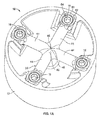
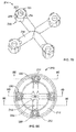
FIG. 1A is a top perspective view of a tie down assembly in accordance with an embodiment of the present invention; -
FIG. 1B is a top perspective view of a cup employed by the tie down assembly shown inFIG. 1A ; -
FIGS. 1C and1D are top and bottom perspective views, respectively, of a crossbar employed by the tie down assembly shown inFIG. 1A ; -
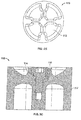
FIGS. 2A and2B are top and bottom plan views, respectively, of the tie down assembly shown inFIG. 1A ; -
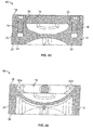
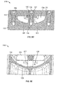
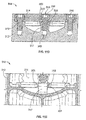
FIG. 2C is a cross-sectional view, taken alongline 2C-2C and looking in the direction of the arrows, of the tie down assembly shown in 5FIG. 2A ; -
FIG. 2D is a cross-sectional view, taken alongline 2D-2D and looking in the direction of the arrows, of the tie down assembly shown inFIG. 2A ; -
FIG. 2E is a cross-sectional view, taken alongline 2E-2E and looking in the direction of tine arrows, of the tie down assembly shown inFIG. 2A ; -
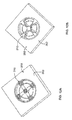
FIGS. 3A and 3B are top and bottom perspective views, respectively, of the tie down assembly shown inFIG. 1A installed within a deck of a vessel; -
FIG.4A is a top perspective view of a tie down assembly in accordance with another embodiment of the present invention; -
FIG.4B is a top perspective view of a cup employed by the tie down assembly shown inFIG. 4A ; -
FIGS. 4C and4D are top and bottom perspective views, 20 respectively, of a crossbar employed by the tie down assembly shown inFIG. 4A ; -
FIGS. 5A and5B are top and bottom plan views, respectively, of the tie down assembly shown inFIG. 4A ; -
FIG. 5C is a cross-sectional view, taken alongline 5C-5C and looking in the direction of the arrows, of the tie down assembly shown inFIG. 5A ; -
FIG.5D is a cross-sectional view, taken alongline 5D-5D and looking in the direction of the arrows, of the tie down assembly shown inFIG. 5A ; -
FIG.5E is a cross-sectional view, taken alongline 5E-5E and looking in the direction of the arrows, of the tie down assembly shown inFIG. 5A ; -
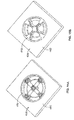
FIGS. 6A and 6B are top and bottom perspective views, respectively, of the tie down assembly shown inFIG. 4A installed within a deck of a vessel; -
FIG.7A is a top perspective view of a tie down assembly in accordance with another embodiment of the present invention; -
FIG. 7B is a top perspective view of a cup employed by the tie down assembly shown inFIG. 7A ; -
FIGS. 7C and7D are top and bottom perspective views, respectively, of a crossbar employed by the tie down assembly shown inFIG. 7A ; -
FIGS. 8A and8B are top and bottom plan views, respectively, of the tie down assembly shown inFIG. 7A ; -
FIG.8C is a cross-sectional view, taken alongline 8C-8C and looking in the direction of the arrows, of the tie down assembly shown inFIG. 8A ; -
FIG. 8D is a cross-sectional view, taken alongline 8D-8D and looking in the direction of the arrows, of the tie down assembly shown inFIG. 8A ; -
FIG.8E is a cross-sectional view, taken alongline 8E-8E and looking in the direction of the tie arrows, of the tie down assembly shown inFIG. 8A ; -
FIGS. 9A and 9B are top and bottom perspective views, respectively, of the tie down assembly shown inFIG. 7A installed within a deck of a vessel; -
FIG. 10A is a top perspective view of a tie down assembly in accordance with another embodiment of the present invention; -
FIG.10B is a top perspective view of a cup employed by the tie down assembly shown inFIG. 10A ; -
FIGS. 10C and10D are top and bottom perspective views, respectively, of a crossbar employed by the tie down assembly shown inFIG. 10A ; -
FIGS. 11A and11B are top and bottom plan views, respectively, of the tie down assembly shown inFIG. 10A ; -
FIG. 11C is a cross-sectional view, taken alongline 11C-11C and looking in the direction of the arrows, of the tie down assembly shown inFIG. 11 A; -
FIG. 11D is a cross-sectional view, taken alongline 11D-11D and looking in the direction of the arrows, of the tie down assembly shown inFIG. 11 A; -
FIG. 11E is a cross-sectional view, taken alongline 11E-11E and looking in the direction of the arrows, of the tie down assembly shown inFIG. 11A ; -
FIGS. 12A and 12B are top and bottom perspective views, respectively, of the tie down assembly shown inFIG. 10A installed within a deck of a vessel; -
FIG. 13A is a top perspective view of a tie down assembly in accordance with another embodiment of the present invention; -
FIG. 13B is a top perspective view of a cup employed by the tie down assembly shown inFIG. 13A ; -
FIGS. 13C and13D are top and bottom perspective views, respectively, of a crossbar employed by the tie down assembly shown inFIG. 13A ; -
FIGS. 14A and14B are top and bottom plan views, respectively, of the tie down assembly shown inFIG. 13A ; -
FIG. 14C is a cross-sectional view, taken alongline 14C-14C and looking in the direction of the arrows, of the tie down assembly shown inFIG. 14A ; -
FIG. 14D is a cross-sectional view, taken alongline 14D-14D and looking in the direction of the arrows, of the tie down assembly shown inFIG. 14A ; -
FIG. 14E is a cross-sectional view, taken alongline 14E-14E and looking in the direction of the arrows, of the tie down assembly shown inFIG. 14A ; -
FIGS. 15A and 15B are top and bottom perspective views, respectively, of the tie down assembly shown inFIG. 13A installed within a deck of a vessel; -
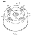
FIG. 16A is a top perspective view of a tie down assembly in accordance with another embodiment of the present invention; -
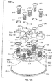
FIG. 16B is an exploded view of the tie down assembly shown inFIG. 16B ; -
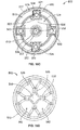
FIGS. 16C and 16D are top and bottom plan views, respectively, of a cup employed by the tie down assembly shown inFIG. 16A ; -
FIGS. 16E and 16F are top and bottom perspective views, respectively, of the tie down assembly shown inFIG. 16A installed within a deck of a vessel; and -
FIG. 16G is a cross-sectional view, taken alongline 16G-16G and looking in the direction of the arrows, of the installed tie down assembly shown inFIG. 16E . - Referring to
FIG. 1A , a tie downassembly 10 includes a cylindrical-shapedcup 12 and across-shaped crossbar 14 that is fastened removably to thecup 12 by a plurality offasteners 16. In an embodiment, thecup 12 is made from aluminum and thecrossbar 14 is made from steel. In other embodiments, thecup 12 is made from an aluminum-magnesium-silicon alloy (6xxxx series alloy), an aluminum-magnesium alloy (5xxxx series alloy), or another marine specified aluminum alloy. In an embodiment, thecrossbar 14 is made from 4130 steel. In other embodiments, thecrossbar 14 is made from other marine specified steel, aluminum, or titanium. In other embodiments, thecup 12 and thecrossbar 14 are made from other suitable materials known in the art, such as other types of metals or metal alloys. In an embodiment, thecup 12 and thecrossbar 14 are produced by forging. In another embodiment, thecup 12 is produced by machining. In other embodiments, thecrossbar 14 is produced by machining, or by forging and machining. While thecup 12 is cylindrical-shaped, it may consist of other shapes and sizes, in accordance with other embodiments. While thecrossbar 14 is cross-shaped, it may consist of other shapes and sizes, in accordance with other embodiments. The features and functions of thecup 12 and thecrossbar 14 shall be described hereinafter. - Referring to
FIGS. 1B and2A through 2E , thecup 12 includes anupper end 18 and alower end 20 that is opposite theupper end 18, and a ring-shapedsidewall 22 that extends from theupper end 18 to thelower end 20. Thecup 12 includes arecess 24 that extends from theupper end 18 and is defined by a concaveinterior surface 26. A plurality ofpockets 28 are formed on theinterior surface 26 of thecup 12. Each of thepockets 28 includes aseat 30 and a pair of opposedangular walls interior surface 26 of thecup 12 to theupper end 18 of thecup 12 and flank theseat 30. Each of thepockets 28 includes a counter bore 34 that is formed within the correspondingseat 30 and extends towards thelower end 20 of thecup 12. Each of the counter bores 34 is sized and shaped to receive a corresponding one of thefasteners 16, which will be described in more detail below. In an embodiment, each of the counter bores 34 includes internal threads (not shown in the Figures). In an embodiment, thecup 12 includes four of thepockets 28, which are arranged in a cross-like pattern (i.e., positioned 90 degrees from each other) on theinterior surface 26 of thecup 12. In other embodiments, thecup 12 may include more or less than four of thepockets 28. - Referring to
FIG. 2B , a lower,exterior surface 36 of thecup 12 includes a plurality ofribs 38 extending therefrom and from thelower end 20 of thecup 12 to acentral portion 40, and are separated from one another by a plurality ofgaps 42. Theribs 38 provide for strength and stiffness, while thegaps 42 result in mass reduction of the tie downassembly 10. In an embodiment, theribs 38 are arranged in a cross-like pattern (i.e., positioned 90 degrees from each other) on theexterior surface 36. In other embodiments, thecup 12 may include more or less than four of theribs 38. - Referring to
FIGS. 1A ,1C and1D , thecrossbar 14 includes a plurality of tubular-shapedmembers 44, each of which has afirst end 46 that intersects with the other first ends 46 at acentral point 48, and afree end 50 opposite thefirst end 46. In an embodiment, all of themembers 44 lie within the same plane. In an embodiment, thecrossbar 14 includes four of themembers 44. In other embodiments, thecrossbar 14 includes more or less than four of themembers 44. In an embodiment, each of themembers 44 includes a hexagonal-shapedhead 52 formed at thefree end 50 thereof and a centrally located, circular-shapedaperture 54 extending through thehead 52. In other embodiments, each of theheads 52 consists of different shapes and sizes, such as square-shaped, circular-shaped, etc. - Referring to
FIGS. 1A through 2E , thecrossbar 14 is fastened to thecup 12 by thefasteners 16. In this regard, thecrossbar 14 is positioned within therecess 24 of thecup 12, such that one ofheads 52 of thecrossbar 14 is positioned within a corresponding one of thepockets 28 of thecup 12. As a result, one of theapertures 54 of themembers 44 of thecrossbar 14 aligns with a corresponding one of the counter bores 34 of thecup 12. Each of thefasteners 16 threadedly engages a corresponding one of the counter bores 34 of thecup 12, thereby securing thecrossbar 14 to thecup 12. In an embodiment, thefasteners 16 include uncoated, high strength bolts made from corrosion resistant materials, such as Monel or stainless steel. In another embodiment, thefasteners 16 include anti-corrosion, coated steel threaded bolts, such as GEOMET® bolts manufactured by Metal Coatings International Inc. In an embodiment, thefasteners 16 include self-sealing bolts having embedded O-rings. In an embodiment, thefasteners 16 include bolts separated from the O-rings and assembled together. In an embodiment, O-rings are positioned within grooves formed within theseats 30 of the pockets 28 (not shown inFIGS. 2A through 2E ) in order to provide water tight seals and corrosion resistance between thepockets 28 and theheads 52 of thecrossbar 14. In an embodiment, the O-rings are made from VITON® brand of synthetic rubber or fluropolymer elastomer, made by DuPont Performance Elastomers LLC. In an embodiment, the counter bores 34 are applied with a water repellent sealant (not shown in the Figures). In an embodiment, the sealant is SIKAFLEX® 221 adhesive sealant. In an embodiment, each of the counter bores 34 is sized and shaped to include threaded inserts (not shown inFIGS. 1A through 2E ) that threadedly engage a corresponding one of thefasteners 16. In an embodiment, the threaded inserts are RECOIL® brand of inserts manufactured by Alcoa Fastening Systems, but other brands of inserts may be utilized. - Referring to
FIGS. 3A and 3B , the tie downassembly 10 is installed within adeck 58 of a vessel having anexterior surface 60 and aninterior surface 62. In an embodiment, thedeck 58 is made from aluminum. In other embodiments, thedeck 58 is made from other materials, such as metals and metal alloys. In an embodiment, thedeck 58 includes a solid portion(s). In another embodiment, thedeck 58 is corrugated (not shown in the Figures). In another embodiment, thedeck 58 is a multi-hollow extrusion (not shown in the Figures). In another embodiment, thedeck 58 is characterized by complex structural geometry (not shown in the Figures). - To install the tie down
assembly 10, a hole is bored in thedeck 58 from theexterior surface 60 to the interior surface 62 (not shown in the Figures). The diameter of the hole is substantially equal to the diameter of thesidewall 22 of thecup 12. Next, the tie downassembly 10 is positioned within the hole. In an embodiment, the radial clearance between thesidewall 22 of thecup 12 and the hole of thedeck 58 is about 0.0197 inches ± 0.004 inches (0.5 mm ± 0.1 mm). In an embodiment, theupper end 18 of thecup 12 protrudes above theexterior surface 60 of thedeck 58, while thelower end 20 of thecup 12 protrudes below theinterior surface 62 of thedeck 58, leaving thecrossbar 14 and therecess 24 of thecup 12 exposed within theexterior surface 60 of thedeck 58. In another embodiment, theupper end 18 of thecup 12 lies flush with theexterior surface 60 of thedeck 58, while thelower end 20 of thecup 12 lies flush with theinterior surface 62 of thedeck 58. To secure the tie downassembly 10 to thedeck 58, theupper end 18 of thecup 12 is welded to theexterior surface 60 of thedeck 58, while thelower end 20 of thecup 12 is welded to theinterior surface 62 of thedeck 58. When thecrossbar 14 is installed within thecup 12, the depth of thepockets 28 ensure that thecrossbar 14 is positioned flush with theupper end 18 of thecup 12. - In an embodiment, the
crossbar 14 is sized and shaped to accommodate the receipt of various tie down connectors, such as hooks, clips, cables, rope, etc. (not shown in the Figures). Thecrossbar 14 provides uniform load distribution for the tie downassembly 10. In this regard, there are tight radial fits between theheads 52 of thecrossbar 14 and thepockets 28 of thecup 12 to react against shear loads. Moreover, the walls of thepockets 28 prevent rotation of thecrossbar 14 relative to thecup 12, especially during lashing, which react against torques and shear loads imparted on thecrossbar 14. Thecrossbar 14 reacts against axial loads as well, which are borne by thefasteners 16. - In the event that the
crossbar 14 requires, inspection, repair or replacement, it is easily removed from thedeck 58 by removing thefasteners 16 from thecrossbar 14 and thecup 12 using standard tools {e.g., socket wrenches, etc.). As a result, thecrossbar 14 is easily lifted out of thecup 12, while thecup 12 remains secured to thedeck 58. Consequently, the entire tie downassembly 10 need not be removed or cut out to inspect, repair or replace thecrossbar 14. - In an embodiment, the
cup 12 is made from aluminum, while thecrossbar 14 is made from steel, as mentioned above. Thus, in an embodiment, the tie downassembly 10 utilizes the advantages of both aluminum and steel. For example, in an embodiment, thecup 12 is lightweight (e.g., approximately 50% weight savings), corrosion resistant, and allows for the tie downassembly 10 to be installed into thealuminum deck 58 without the need for costly and lengthy manufacturing and installation processes. Accordingly, the tie downassembly 10 does not require any changes in a shipbuilder's manufacturing process, while at the same time offers the advantages of being lightweight and allowing easy replacement and inspection of theassembly 10. Lower weight savings also translates into lower fuel consumption over the lifetime of the vessel. On the other hand, thesteel crossbar 14 maintains high strength, especially during lashing. In addition, the tie downassembly 10 requires minimal assembly time and skill to install, thereby reducing installation costs. Last but not least, the tie downassembly 10 is compact and requires less space to install. - In an embodiment, the
crossbar 14 may be coated with a coating for preventing wear from where thecrossbar 14 makes contact with the tie-down hooks. In an embodiment, the coating composition may consist of an aluminum/stainless steel blend manufactured by Alcoa Inc., and which is the subject ofU.S. Patent Nos. 5,884,388 and6,290,032 , which are incorporated herein by reference. In other embodiments, the coating may include an electroless nickel phosphorous coating, such as NIBORE™ brand of coating, a diamond chrome coating, a hard chrome coating, or a nickel cobalt coating, all of which are supplied by Bales Mold Service Inc. of Downers Grove, Illinois. In other embodiments, the coating may include a wear-resistant cubic boron nitride, hard powder coating, such as TUFFTEK® brand of coating supplied by NanoMech, LLC d/b/a Duralor of Springdale, Arkansas. In other embodiments, other suitable coatings that prevent wear and are known in the art may be utilized. -
FIGS. 4A through 6B illustrate a tie downassembly 110 in accordance with another embodiment of the present invention. The tie downassembly 110 includes acup 112, acrossbar 114, and a plurality offasteners 116 that removably fasten thecrossbar 114 to thecup 112. The tie downassembly 110 is similar in structure and function to the tie downassembly 10, with certain differences described hereinafter. More particularly, thecup 112 includes a centrally located,elongated boss member 117 extending upwardly from aninterior surface 126 of arecess 124. Theboss member 117 includes a centrally-located threaded counter bore 119 (seeFIGS. 4B and5D ). Thecrossbar 114 is similar in structure and function to thecrossbar 14, except that thecrossbar 114 includes a centrally located, circular-shapedaperture 127 that extends through thecentral point 148 of thecrossbar 114. - Referring to
FIGS. 4A through 5E , thecrossbar 114 is fastened to thecup 112 by thefasteners 116 in the same manner as described above for the tie downassembly 10, with the addition that thecentral portion 148 of thecrossbar 114 is attached to theboss member 117 of thecup 112 by one of thefasteners 116. This additional attachment point provides greater strength for thecrossbar 114. Referring toFIGS. 6A and 6B , the tie downassembly 110 is secured to adeck 158 of a vessel having anexterior surface 160 and aninterior surface 162. The tie downassembly 110 is installed to thedeck 158 in a manner similar to the tie downassembly 10 as described above. -
FIGS. 7A through 9B illustrate a tie downassembly 210 in accordance with another embodiment of the present invention. The tie downassembly 210 includes acup 212, acrossbar 214, and a plurality offasteners 216 that fasten thecrossbar 214 to thecup 212. The tie downassembly 210 is similar in structure and function to the tie downassembly 10, with certain differences described hereinafter. More particularly, thecup 212 includes a plurality ofseats 230, each of which includes a raisedportion 231 extending upwardly therefrom. Thecrossbar 214 is similar in structure and function to thecrossbar 14, except that thecrossbar 214 includes a plurality ofmembers 244, each of which includes a hexagonal-shapedhead 252 formed at afree end 250 thereof, a centrally located, circular-shapedaperture 254 extending through thehead 252, and a pair ofopposed tabs 255 that extend downwardly from the head 252 (seeFIG. 8C ). Referring toFIGS. 7A through 8E , thecrossbar 214 is fastened to thecup 212 by thefasteners 216 in the same manner as described above for the tie downassembly 10, with the addition that the each pair of thetabs 255 of thecrossbar 214 is fitted around a corresponding one of the raisedportions 231 of thecup 212. As a result, the engagement between thetabs 255 of thecrossbar 214 and the raisedportions 231 of thecup 212 inhibits rotation of thecrossbar 214 relative to thecup 212. Referring toFIGS. 9A and 9B , the tie downassembly 210 is secured to adeck 258 of a vessel having anexterior surface 260 and aninterior surface 262. The tie downassembly 210 is installed to thedeck 258 in a manner similar to the tie downassembly 10 as described above. -
FIGS. 10A though 12B illustrate a tie downassembly 310 in accordance with another embodiment of the present invention. The tie downassembly 310 includes acup 312, acrossbar 314, and a plurality offasteners 316 that removably fasten thecrossbar 314 to thecup 312. The tie downassembly 310 is similar in structure and function to the tie downassemblies cup 312 includes a centrally located,elongated boss member 317 extending upwardly from aninterior surface 326 of arecess 324. Theboss member 317 includes a centrally-located threadedaperture 319. Thecrossbar 314 is similar in structure and function to thecrossbar 214, except that thecrossbar 314 includes a centrally located, circular-shapedaperture 327 that extends through thecentral point 348. In an embodiment, theaperture 327 includes internal threads (not shown in the Figures) that threadedly engage afastener 316. Referring toFIGS. 10A through 10E , thecrossbar 314 is fastened to thecup 312 by thefasteners 316 in the same manner as described above for the tie downassembly 210, with the addition that thecentral portion 348 of thecrossbar 314 is attached to theboss member 317 of thecup 312 by one of thefasteners 316. This additional attachment point provides greater strength for thecrossbar 314. Moreover, each pair oftabs 355 of thecrossbar 314 is fitted around a corresponding one of raisedportions 331 of thecup 312. As a result, the engagement between thetabs 355 of thecrossbar 314 and the raisedportions 331 of thecup 312 inhibits rotation of thecrossbar 314 relative to thecup 312. Referring toFIGS. 12A and 12B , the tie downassembly 310 is secured to adeck 358 of a vessel having anexterior surface 360 and aninterior surface 362. The tie downassembly 310 is installed to thedeck 358 in a manner similar to the tie downassembly 10 as described above.FIGS. 13A to 15B illustrate a tie downassembly 410 in accordance with another embodiment of the present invention. The tie downassembly 410 includes acup 412, acrossbar 414, and a plurality offasteners 416 that removably fasten thecrossbar 414 to thecup 412. The tie downassembly 410 is similar in structure and function to the tie downassembly 310, with certain differences as described below. More particularly, thecup 312 includes a centrally locatedaperture 413 formed within aninterior surface 426 of a recess 424 (seeFIGS. 13B and14D ). In an embodiment, theaperture 413 includes internal threads 415 (seeFIG. 14D ). Thecrossbar 414 is similar in structure and function to thecrossbar 314, except that thecrossbar 414 includes a centrally located stem 421 that extends perpendicularly frommembers 444 at acentral point 448. - The
stem 421 has afirst end 423 connected to thecentral point 448 and afree end 425 opposite to thefirst end 423. In an embodiment, thestem 421 is tubular shaped. In another embodiment, thestem 421 is conical shaped. A centrally located, circular-shapedaperture 427 extends through thecentral point 448 of thecrossbar 444 to thefree end 423 of thestem 421. - Referring to
FIGS. 14A through 14E , thecrossbar 414 is fastened to thecup 412 by thefasteners 416 in the same manner as described above for the tie downassembly 310, with the addition that thestem 421 of thecrossbar 414 is attached to theinterior surface 426 of thecup 412 by one of thefasteners 416, which threadedly engages and thethreads 415 of theaperture 413 of thecup 412. This additional attachment point provides greater strength to thecrossbar 414. Referring toFIGS. 15A and 15B , the tie downassembly 410 is secured to adeck 458 of a vessel having anexterior surface 460 and aninterior surface 462. The tie downassembly 410 is installed to thedeck 458 in a manner similar to the tie downassembly 10 as described above. -
FIGS. 16A to 16G illustrate a tie downassembly 10 in accordance with another embodiment of the present invention. The tie downassembly 510 includes acup 512, acrossbar 514, and a plurality offasteners 516 that removably fasten thecrossbar 514 to thecup 512. The tie downassembly 510 is similar in structure and function to the tie downassembly 110, with certain differences as described below. More particularly, referring toFIGS. 16B through 16D , thecup 512 includes anupper end 518 and alower end 520 that is opposite theupper end 518, and a ring-shapedsidewall 522 that extends from theupper end 518 to the lower end 520 (seeFIG. 16B ). In an embodiment, thecup 512 includes a circular-shapedflange 511 extending outwardly from thesidewall 522 proximate to the lower end 520 (seeFIG. 16B ). In an embodiment, theflange 511 need not be included. - Still referring to
FIGS. 16B through 16D , in an embodiment, thecup 512 includes arecess 524 that extends from theupper end 518 and is defined a circular-shapedinner wall 513 and aninterior surface 526. In an embodiment, theinner wall 513 includes a ring-shapedupper surface 515 formed proximate to theupper end 518. In an embodiment, theupper surface 515 includes abeveled portion 517. In another embodiment, theupper surface 515 need not include thebeveled portion 517. A plurality of square-shapedpockets 528 are formed within theinner wall 513 and extend from theupper surface 515 to theinterior surface 526. Each of thepockets 528 includes a square-shaped, raisedseat 530 extending upwardly from theinterior surface 526. Eachseat 530 is positioned intermediate a pair of corresponding opposedwalls 532 that extend upwardly from theinterior surface 526 of thecup 512 to theupper end 528 of thecup 512. Each of theseats 530 includes abore 534 that extends towards thelower end 520 of thecup 512. Each of thebores 534 is sized and shaped to receive a corresponding one of thefasteners 516, which will be described in more detail below. In an embodiment, each of thebores 534 includes internal threads 519 (not shown inFIGS. 16B through 16D , but seeFIG. 16G ). In an embodiment, each of theseats 530 includes a square-shaped steppedportion 521, forming a square-shapededge portion 523 that is sized and shaped to receive a square-shaped gasket 525 (which are shown inFIG. 16B ). Thegaskets 525 provide water tight seals and corrosion resistance between thecup 512 and thecrossbar 514, and protect the threads of thefasteners 516 from corrosion. In an embodiment, thegaskets 525 are made from VITON® rubber/elastomer as described above. In an embodiment, thecup 512 includes four of thepockets 528 and four of the correspondingseats 530, which are arranged in a cross-like pattern (i.e., positioned 90 degrees from each other). In other embodiments, thecup 512 may include more or less than four of thepockets 528 and thecorresponding seats 530. - In an embodiment, the
cup 512 includes a centrally-located, circular-shaped raisedseat 535 extending upwardly from theinterior surface 526 of arecess 524. Theseat 535 includes a steppedportion 537 forming a circular-shapededge 539 that is sized and shaped to receive an O-ring 541 (which is shown inFIG. 16B ). In an embodiment, the O-ring 541 is made from VITON® rubber/elastomer as described above, and provides sealing and corrosion resistance functions similar to those of thegaskets 525. Thecentral seat 535 further includes centrally-located threadedbore 543, whose purpose shall be described hereinafter. - In an embodiment, each of the
bores 534 and thebore 543 is sized and shaped to receive a threadedinsert 545 that threadedly engage a corresponding one of the fasteners 516 (seeFIG. 16B ). In an embodiment, the threadedinserts 545 are RECOIL® brand of inserts manufactured by Alcoa Fastening Systems, but other brands of theinserts 545 may be utilized. In another embodiment, theinserts 545 need note be utilized and thefasteners 516 may threadedly engage thebores - Referring to
FIG. 16D , a lower,exterior surface 536 of thecup 512 includes a plurality ofribs 538 extending therefrom and from thelower end 520 of thecup 512 to acentral portion 540, and are separated from one another by a plurality ofgaps 542. Theribs 538 provide for strength and stiffness, while thegaps 542 result in mass reduction of the tie downassembly 510. In an embodiment, theribs 538 are arranged in a cross-like pattern (i.e., positioned 90 degrees from each other) on theexterior surface 536. In other embodiments, thecup 512 may include more or less than four of theribs 538. - Referring to
FIG. 16B , thecrossbar 514 includes a plurality of tubular-shapedmembers 544, each of which has afirst end 546 that intersects with the other first ends 546 at acentral portion 548, and afree end 550 opposite thefirst end 546. A centrally located, circular-shapedaperture 549 that extends through thecentral portion 548. In an embodiment, all of themembers 544 lie within the same plane. In an embodiment, thecrossbar 514 includes four of themembers 544. In other embodiments, thecrossbar 514 includes more or less than four of themembers 544. In an embodiment, each of themembers 544 includes a square-shapedhead 552 formed at thefree end 550 thereof and a centrally located, circular-shapedaperture 554 extending through thehead 552. In other embodiments, each of theheads 552 consists of different shapes and sizes, such as square-shaped, circular-shaped, etc. - In a number of embodiments, the
cup 512 and thecrossbar 514 may be made from the same materials as described above with respect to the tie downassembly 10, e.g., aluminum, steel, titanium, aluminum alloys. In an embodiment, thecup 512 and thecrossbar 514 are produced by forging. In another embodiment, thecup 512 is produced by machining. - Referring to
FIGS. 16A ,16B and16G , thecrossbar 514 is fastened to thecup 512 by thefasteners 516. In this regard, thecrossbar 514 is positioned within therecess 524 of thecup 512, such that one ofheads 552 of thecrossbar 514 is positioned within a corresponding one of thepockets 528 of thecup 512. As a result, one of theapertures 554 of themembers 544 of thecrossbar 514 aligns with a corresponding one of thebores 534 of thecup 512, while thecentral aperture 549 of thecentral portion 548 of thecrossbar 514 aligns with thecentral bore 543 of theseat 535 of thecup 512. Each of thefasteners 516 threadedly engages a corresponding one of thebores crossbar 514 to thecup 512. In an embodiment, O-rings 547 are positioned withingrooves 551 formed within the crossbar 514 (seeFIG. 16G ) in order to provide water tight seals and corrosion resistance between thepockets 528 and theheads 552 of thecrossbar 514, and protect the threads of thefasteners 516 from corrosion. In an embodiment, the O-rings 547 are made from VITON® rubber/elastomer as described above. - Referring to
FIGS. 16E through 16G , the tie downassembly 510 is secured to adeck 558 of a vessel having anexterior surface 560 and aninterior surface 562. The tie downassembly 510 is installed to thedeck 558 in a manner similar to that described above. In an embodiment, theupper end 518 of thecup 512 lies flush with theexterior surface 560 of thedeck 558. In an embodiment, thebeveled portion 517 of thecup 512 facilitates a good flush deck weld between thecup 512 and theexterior surface 560 of thedeck 558. In an embodiment, the radial clearance between thesidewall 522 of theassembly 510 and the hole of thedeck 558 is about 0.0197 inches ± 0.004 inches (0.5 mm ± 0.1 mm). - In an embodiment, the
flange 511 of thecup 512 abuts thelower surface 562 of thedeck 558. In an embodiment, theflange 511, having wrought properties, carries a vertical load applied by the connectors to the tie downassembly 510, and, therefore, such vertical load is not entirely held by the welds. In another embodiment, as indicated above, the tie downassembly 510 does not include theflange 511. In an embodiment, there exists a tight fit between theheads 552 of thecrossbar 514 and thepockets 528 of thecup 512. In an embodiment, the term "tight fit" means a nominal gap of about 0.004 inches (0.1 mm) ± 0.004 inches (0.1 mm). While thefasteners 516 are designed to carry all loads, the tight fit between thecross 514 and thecup 512 may carry all of the shear and torsional loads that may be developed should slippage occur under the heads of thefasteners 516. In addition, the tie downassembly 510 minimizes open space on thedeck 558, and, thus, reduces tripping hazards. It will be understood that the tie downassemblies 10 through 510 described herein are merely exemplary and that a person skilled in the art may make many variations and modifications without departing from the full spirit and the scope of the embodiment described herein. For example, the tie down assemblies may include failsafe components that enable them to fail prior to damaging the decking if overloaded/thereby saving high repair costs. Although the tie down assemblies are welded to a deck, they could be attached to the deck by other suitable means known in the art, such as fasteners, adhesives, etc. In embodiments for the tie downassemblies fasteners fasteners fasteners assemblies fasteners fasteners fasteners cups
Claims (9)
- A tie down assembly (110, 210, 310), comprising:- a cup (112, 212, 312) having a recess formed within the cup (112, 212, 312) and defining an interior surface (126), and a plurality of seats (230) extending from the interior surface (126), each of the plurality of seats (230) including a bore; and- a crossbar (114, 214, 314) having a central portion (148, 348) and a plurality of members (244) extending from the central portion (148, 348), each of the plurality of members (244) includes a free end (250) having a head (252) and an aperture formed within the head (252), the crossbar (114, 214, 314) being fastened removably to the cup (112, 212, 312) by a plurality of fasteners (116, 216, 316) such that the crossbar (114, 214, 314) is positioned within the recess of the cup (112, 212, 312), each of the aligned apertures of the heads (252) of the plurality of members (244) of the crossbar (114, 214, 314) and the bores of the plurality of seats (230) of the cup (112, 212, 312) being sized and shaped to receive a corresponding one of the plurality of fasteners (116, 216, 316),
wherein the cup (112, 212, 312) includes a centrally located, elongated boss member (117, 317) extending upwardly from the interior surface (126) of the recess, the boss member (117, 317) including a centrally-located threaded counter bore (119, 319),
wherein the crossbar (114, 214, 314) includes a centrally located, circular-shaped aperture (127, 327) that extends through the central portion (148, 348) of the crossbar (114, 214, 314), the central portion (148, 348) of the crossbar (114, 214, 314) being fastened removably to the boss member (117, 317) by one of the plurality of fasteners (116, 216, 316). - The tie down assembly (110, 210, 310) of Claim 1, wherein each of the plurality of seats (230) includes a raised portion (231, 331) extending upwardly therefrom, wherein each of the plurality of members (244) of the crossbar (114, 214, 314) includes a hexagonal-shaped head (252) formed at the free end (250) thereof, a centrally located, circular-shaped aperture (254) extending through the head (252), and a pair of opposed tabs (255, 355) that extend downwardly from the head (252), the each pair of the tabs (255, 355) of the crossbar (114, 214, 314) being fitted around a corresponding one of the raised portions (231, 331) of the cup (112, 212, 312).
- The tie down assembly (110, 210, 310) of Claim 1 or 2, wherein the centrally located, circular-shaped aperture (127, 327) includes internal threads that are adapted to threadedly engage one of the plurality of fasteners (116, 216, 316).
- The tie down assembly (110, 210, 310) of one of the preceding Claims, wherein the cup (112, 212, 312) includes a plurality of pockets formed within the inner wall of the cup (112, 212, 312), each of the plurality of seats (230) of the cup (112, 212, 312) is positioned within a corresponding one of the plurality of pockets of the cup (112, 212, 312).
- The tie down assembly (110, 210, 310) of Claim 4, wherein each of the plurality of pockets of the cup (112, 212, 312) includes a pair of sidewalls, each of the heads (252) of the plurality of members (244) of the crossbar (114, 214, 314) is positioned between a corresponding one of the pair of sidewalls.
- The tie down assembly (110, 210, 310) of any of the preceding Claims,
wherein the plurality of seats (230) of the cup (112, 212, 312) includes four of the seats (230), and the plurality of members (244) of the crossbar (114, 214, 314) includes four of the members (244). - The tie down assembly (110, 210, 310) of any of the preceding Claims,
wherein the tie down assembly (110, 210, 310) is adapted to be installed within a structure having a first surface, a second surface opposite the first surface, and a hole extending from the first surface to the second surface, the hole being sized and shaped to receive the cup (112, 212, 312), and, when the cup (112, 212, 312) is installed within the hole, the upper end of the cup (112, 212, 312) lies substantially flush with the first surface of the structure. - The tie-down assembly of any of the preceding Claims, wherein the cup (112, 212, 312) is made from aluminum and the crossbar (114, 214, 314) is made from steel.
- The tie down assembly (110, 210, 310) of Claim 7, wherein the structure is made from aluminum, and wherein the structure includes a deck (258, 358) of a vessel.
Applications Claiming Priority (2)
| Application Number | Priority Date | Filing Date | Title |
|---|---|---|---|
| US33631410P | 2010-01-20 | 2010-01-20 | |
| EP10782775.0A EP2464562B1 (en) | 2010-01-20 | 2010-11-18 | Tie down assembly |
Related Parent Applications (2)
| Application Number | Title | Priority Date | Filing Date |
|---|---|---|---|
| EP10782775.0A Division-Into EP2464562B1 (en) | 2010-01-20 | 2010-11-18 | Tie down assembly |
| EP10782775.0A Division EP2464562B1 (en) | 2010-01-20 | 2010-11-18 | Tie down assembly |
Publications (2)
| Publication Number | Publication Date |
|---|---|
| EP2759466A1 true EP2759466A1 (en) | 2014-07-30 |
| EP2759466B1 EP2759466B1 (en) | 2016-04-20 |
Family
ID=43858775
Family Applications (2)
| Application Number | Title | Priority Date | Filing Date |
|---|---|---|---|
| EP10782775.0A Not-in-force EP2464562B1 (en) | 2010-01-20 | 2010-11-18 | Tie down assembly |
| EP14154442.9A Not-in-force EP2759466B1 (en) | 2010-01-20 | 2010-11-18 | Tie down assembly |
Family Applications Before (1)
| Application Number | Title | Priority Date | Filing Date |
|---|---|---|---|
| EP10782775.0A Not-in-force EP2464562B1 (en) | 2010-01-20 | 2010-11-18 | Tie down assembly |
Country Status (5)
| Country | Link |
|---|---|
| US (2) | US8505868B2 (en) |
| EP (2) | EP2464562B1 (en) |
| CN (2) | CN201907633U (en) |
| AU (1) | AU2010343262B2 (en) |
| WO (1) | WO2011090542A1 (en) |
Families Citing this family (12)
| Publication number | Priority date | Publication date | Assignee | Title |
|---|---|---|---|---|
| EP2429888A2 (en) * | 2009-05-14 | 2012-03-21 | Alcoa Inc. | Tie down assembly |
| US8360385B2 (en) * | 2009-08-13 | 2013-01-29 | Alcoa Inc. | Tie down assembly |
| EP2464562B1 (en) * | 2010-01-20 | 2014-03-26 | Alcoa Inc. | Tie down assembly |
| US8672270B2 (en) * | 2012-07-06 | 2014-03-18 | The United States Of America As Represented By The Secretary Of The Army | Tie down and jack fitting assembly for helicopter |
| CN103057666A (en) * | 2013-01-29 | 2013-04-24 | 大连中远船务工程有限公司 | Ship mooring hole plate |
| ES2796974T3 (en) * | 2014-12-23 | 2020-11-30 | Arcelormittal S A | Thrust bearing and holding in a roller bearing assembly |
| KR102383481B1 (en) * | 2015-09-04 | 2022-04-06 | 피에스에이 인터내셔널 피티이 엘티디 | Container lashing method and container lashing system |
| US10118674B1 (en) | 2016-03-10 | 2018-11-06 | Peck & Hale, L.L.C. | Cargo lashing fitting |
| US11052813B1 (en) | 2018-02-21 | 2021-07-06 | Peck & Hale, L.L.C. | Cargo lashing fitting |
| US11046233B1 (en) | 2018-12-18 | 2021-06-29 | Peck & Hale, L.L.C. | Cargo lashing fitting |
| CN116654186A (en) * | 2023-05-29 | 2023-08-29 | 上海船舶研究设计院 | A binding and fixing device integrating a binding strap and a fastening point |
| USD1085841S1 (en) * | 2023-07-21 | 2025-07-29 | Precision Tech Manufacturing, LLC | Folding pad eye |
Citations (2)
| Publication number | Priority date | Publication date | Assignee | Title |
|---|---|---|---|---|
| US3927623A (en) * | 1974-06-17 | 1975-12-23 | Gen Dynamics Corp | Lashing socket cover |
| DE19904366C1 (en) * | 1999-02-03 | 2000-06-21 | Sommer Fahrzeugbau Gmbh & Co K | Fixing unit for attachment esp. to the HGVs or trailers comprises polygonal one-piece section with fixing stops |
Family Cites Families (40)
| Publication number | Priority date | Publication date | Assignee | Title |
|---|---|---|---|---|
| US2962245A (en) * | 1958-11-03 | 1960-11-29 | Aeroquip Corp | Attachment fitting |
| US3365162A (en) | 1966-04-22 | 1968-01-23 | Frank L. Davis | Flush seating, watertight and airtight anchorages for tiedown gear and other equipment |
| US3427996A (en) | 1967-03-28 | 1969-02-18 | Matias Alvarados | Rope hook |
| US3694866A (en) | 1970-10-23 | 1972-10-03 | Roy R Maier | Vehicle hook |
| US3754525A (en) * | 1972-01-20 | 1973-08-28 | A Leighty | Portable anchor unit |
| US3888190A (en) | 1974-01-10 | 1975-06-10 | Henry W Bigge | Tiedown lug |
| US4151974A (en) | 1976-09-29 | 1979-05-01 | Kuhn Charles J | Anchor |
| US4091744A (en) | 1976-10-26 | 1978-05-30 | Aeroquip Corporation | Portable deck cleat |
| US4193529A (en) | 1977-01-24 | 1980-03-18 | The United States Of America As Represented By The Secretary Of The Navy | Method for interconnecting dissimilar metals welding to an explosively bonded bimetallic coupling |
| US4099661A (en) | 1977-01-24 | 1978-07-11 | The United States Of America As Represented By The Secretary Of The Navy | Method for connecting bimetallic members by explosive bonding |
| DE3266944D1 (en) * | 1981-08-10 | 1985-11-21 | Dieter Borchardt | Lashing bar for fastening containers |
| US4907921A (en) | 1984-01-03 | 1990-03-13 | A. L. Hansen Manufacturing Co. | Tie-down assembly |
| US4877361A (en) | 1986-12-16 | 1989-10-31 | Sterling Plastic & Rubber Products, Inc. | Elastomeric insert for container lashing |
| US4945849A (en) | 1988-03-28 | 1990-08-07 | Bass Pro Shops, Inc. | Retractable cleat |
| GB8923458D0 (en) | 1989-10-18 | 1989-12-06 | York Trailer Co Ltd | Improvements in and relating to cargo restraint in refrigerated vehicles and containers |
| US5052869A (en) | 1990-08-29 | 1991-10-01 | A. L. Hansen Mfg. Co. | Tie down assembly |
| US6290032B1 (en) | 1995-05-12 | 2001-09-18 | Alcoa Inc. | Friction-wear aluminum part and associated method |
| US5884388A (en) | 1995-05-12 | 1999-03-23 | Aluminum Company Of America | Method for manufacturing a friction-wear aluminum part |
| US5535694A (en) | 1995-09-21 | 1996-07-16 | Accon Marine, Inc | Retractable cleat with a sealed housing |
| US6585466B2 (en) | 1999-05-14 | 2003-07-01 | Holland Company | Railcar anchor and load snugger arrangement |
| US6494651B1 (en) | 1999-05-14 | 2002-12-17 | Holland Company | Railcar anchor and load snugger arrangement |
| DE19933424A1 (en) * | 1999-07-12 | 2001-01-18 | Macgregor Conver Gmbh | Stowage piece to secure the position of containers on board ships |
| US6764259B1 (en) | 2002-05-24 | 2004-07-20 | John Preta | Retractable anchor device and method of mounting the anchor device |
| GB2394482B (en) | 2002-10-21 | 2004-06-16 | Frank James Hardie | Improvements to security chain anchors |
| US20040099197A1 (en) | 2002-11-26 | 2004-05-27 | King William E. | Pull-up cleat |
| CN2679026Y (en) * | 2004-03-18 | 2005-02-16 | 上海中升贸易有限公司 | Single buried base frame |
| AU2005200893A1 (en) | 2004-04-01 | 2005-10-20 | Lockheed Martin Corporation | Anchoring system |
| ATE427261T1 (en) | 2004-06-22 | 2009-04-15 | Fincantieri Cantieri Navali It | FASTENING, IN PARTICULAR FOR MOORING VEHICLES ON BOARD SHIPS, AND METHOD FOR ATTACHING SUCH FASTENING TO THE DECK |
| US7134819B2 (en) | 2004-12-20 | 2006-11-14 | A.L. Hansen Manufacturing Co. | Tie-down assembly |
| US7390155B1 (en) | 2005-07-07 | 2008-06-24 | Carroll Diaz | Deck anchor for removably connecting to eyelets |
| US20080087782A1 (en) | 2006-09-06 | 2008-04-17 | Scott Sutherland | Accessories for universal mounting system |
| US7798753B2 (en) | 2007-03-05 | 2010-09-21 | Hyundai Translead | Cargo container with peripheral wall structure reinforced by side post assemblies |
| US8220209B2 (en) | 2007-03-26 | 2012-07-17 | Ville De Montreal | Ground anchor |
| US7686551B2 (en) | 2007-04-18 | 2010-03-30 | Black & Gray Design & Manufacturing, Inc. | Tie-down anchor system and method |
| AU2009242964A1 (en) | 2008-04-29 | 2009-11-05 | Rohan Perkins | Recessed attachment point |
| US8075232B2 (en) | 2009-05-05 | 2011-12-13 | Sierra Pacific Engineering And Products | System and method for securing cargo to a load bearing surface |
| EP2429888A2 (en) * | 2009-05-14 | 2012-03-21 | Alcoa Inc. | Tie down assembly |
| US8360385B2 (en) | 2009-08-13 | 2013-01-29 | Alcoa Inc. | Tie down assembly |
| EP2464562B1 (en) * | 2010-01-20 | 2014-03-26 | Alcoa Inc. | Tie down assembly |
| US8568070B2 (en) | 2010-11-01 | 2013-10-29 | Peck & Hale, L.L.C. | Cargo lashing fitting |
-
2010
- 2010-11-18 EP EP10782775.0A patent/EP2464562B1/en not_active Not-in-force
- 2010-11-18 US US12/948,931 patent/US8505868B2/en active Active
- 2010-11-18 WO PCT/US2010/057189 patent/WO2011090542A1/en not_active Ceased
- 2010-11-18 AU AU2010343262A patent/AU2010343262B2/en not_active Ceased
- 2010-11-18 EP EP14154442.9A patent/EP2759466B1/en not_active Not-in-force
-
2011
- 2011-01-19 CN CN 201120015866 patent/CN201907633U/en not_active Expired - Lifetime
- 2011-01-19 CN CN2011100211263A patent/CN102126540B/en not_active Expired - Fee Related
-
2013
- 2013-08-12 US US13/964,587 patent/US8814125B2/en active Active
Patent Citations (2)
| Publication number | Priority date | Publication date | Assignee | Title |
|---|---|---|---|---|
| US3927623A (en) * | 1974-06-17 | 1975-12-23 | Gen Dynamics Corp | Lashing socket cover |
| DE19904366C1 (en) * | 1999-02-03 | 2000-06-21 | Sommer Fahrzeugbau Gmbh & Co K | Fixing unit for attachment esp. to the HGVs or trailers comprises polygonal one-piece section with fixing stops |
Also Published As
| Publication number | Publication date |
|---|---|
| EP2464562B1 (en) | 2014-03-26 |
| US20110284716A1 (en) | 2011-11-24 |
| US20140042290A1 (en) | 2014-02-13 |
| WO2011090542A1 (en) | 2011-07-28 |
| EP2464562A1 (en) | 2012-06-20 |
| AU2010343262A1 (en) | 2012-02-02 |
| AU2010343262B2 (en) | 2012-11-29 |
| US8814125B2 (en) | 2014-08-26 |
| CN201907633U (en) | 2011-07-27 |
| CN102126540A (en) | 2011-07-20 |
| EP2759466B1 (en) | 2016-04-20 |
| US8505868B2 (en) | 2013-08-13 |
| CN102126540B (en) | 2013-11-27 |
Similar Documents
| Publication | Publication Date | Title |
|---|---|---|
| EP2464562B1 (en) | Tie down assembly | |
| US8360385B2 (en) | Tie down assembly | |
| AU2010248095B2 (en) | Tie down assembly | |
| US7134819B2 (en) | Tie-down assembly | |
| US8777278B2 (en) | Flange assembly with improved serviceability | |
| US5827025A (en) | Lug nut disc spring assembly | |
| US11713005B2 (en) | Method and fastening device for fastening a lining element | |
| AU2013201698B2 (en) | Tie down assembly | |
| CN201694357U (en) | A tie-down assembly suitable for installation in structures | |
| US20240003366A1 (en) | Integral retention clip with nut | |
| NL2036277B1 (en) | Anchor hook buckle | |
| DE102017001991A1 (en) | Motor vehicle with lashing eye | |
| EP3222559B1 (en) | Expanding clamping twistlock for iso aperture securement | |
| US20240308410A1 (en) | Dual ring recessed pad eye | |
| US20250001818A1 (en) | Lock plate | |
| US11465548B1 (en) | Load restraint fastener for use with different load restraint attachments | |
| US20060233606A1 (en) | Fastener arrangement for fastening a detachable panel | |
| CA2562524A1 (en) | Coupling device for load securement |
Legal Events
| Date | Code | Title | Description |
|---|---|---|---|
| PUAI | Public reference made under article 153(3) epc to a published international application that has entered the european phase |
Free format text: ORIGINAL CODE: 0009012 |
|
| 17P | Request for examination filed |
Effective date: 20140210 |
|
| AC | Divisional application: reference to earlier application |
Ref document number: 2464562 Country of ref document: EP Kind code of ref document: P |
|
| AK | Designated contracting states |
Kind code of ref document: A1 Designated state(s): AL AT BE BG CH CY CZ DE DK EE ES FI FR GB GR HR HU IE IS IT LI LT LU LV MC MK MT NL NO PL PT RO RS SE SI SK SM TR |
|
| GRAP | Despatch of communication of intention to grant a patent |
Free format text: ORIGINAL CODE: EPIDOSNIGR1 |
|
| INTG | Intention to grant announced |
Effective date: 20151016 |
|
| GRAS | Grant fee paid |
Free format text: ORIGINAL CODE: EPIDOSNIGR3 |
|
| GRAA | (expected) grant |
Free format text: ORIGINAL CODE: 0009210 |
|
| AC | Divisional application: reference to earlier application |
Ref document number: 2464562 Country of ref document: EP Kind code of ref document: P |
|
| AK | Designated contracting states |
Kind code of ref document: B1 Designated state(s): AL AT BE BG CH CY CZ DE DK EE ES FI FR GB GR HR HU IE IS IT LI LT LU LV MC MK MT NL NO PL PT RO RS SE SI SK SM TR |
|
| REG | Reference to a national code |
Ref country code: GB Ref legal event code: FG4D |
|
| REG | Reference to a national code |
Ref country code: CH Ref legal event code: EP |
|
| REG | Reference to a national code |
Ref country code: AT Ref legal event code: REF Ref document number: 792112 Country of ref document: AT Kind code of ref document: T Effective date: 20160515 |
|
| REG | Reference to a national code |
Ref country code: IE Ref legal event code: FG4D |
|
| REG | Reference to a national code |
Ref country code: DE Ref legal event code: R096 Ref document number: 602010032738 Country of ref document: DE |
|
| REG | Reference to a national code |
Ref country code: NL Ref legal event code: FP |
|
| REG | Reference to a national code |
Ref country code: LT Ref legal event code: MG4D |
|
| REG | Reference to a national code |
Ref country code: NO Ref legal event code: T2 Effective date: 20160420 |
|
| REG | Reference to a national code |
Ref country code: AT Ref legal event code: MK05 Ref document number: 792112 Country of ref document: AT Kind code of ref document: T Effective date: 20160420 |
|
| PG25 | Lapsed in a contracting state [announced via postgrant information from national office to epo] |
Ref country code: FI Free format text: LAPSE BECAUSE OF FAILURE TO SUBMIT A TRANSLATION OF THE DESCRIPTION OR TO PAY THE FEE WITHIN THE PRESCRIBED TIME-LIMIT Effective date: 20160420 Ref country code: PL Free format text: LAPSE BECAUSE OF FAILURE TO SUBMIT A TRANSLATION OF THE DESCRIPTION OR TO PAY THE FEE WITHIN THE PRESCRIBED TIME-LIMIT Effective date: 20160420 Ref country code: LT Free format text: LAPSE BECAUSE OF FAILURE TO SUBMIT A TRANSLATION OF THE DESCRIPTION OR TO PAY THE FEE WITHIN THE PRESCRIBED TIME-LIMIT Effective date: 20160420 |
|
| PG25 | Lapsed in a contracting state [announced via postgrant information from national office to epo] |
Ref country code: AT Free format text: LAPSE BECAUSE OF FAILURE TO SUBMIT A TRANSLATION OF THE DESCRIPTION OR TO PAY THE FEE WITHIN THE PRESCRIBED TIME-LIMIT Effective date: 20160420 Ref country code: LV Free format text: LAPSE BECAUSE OF FAILURE TO SUBMIT A TRANSLATION OF THE DESCRIPTION OR TO PAY THE FEE WITHIN THE PRESCRIBED TIME-LIMIT Effective date: 20160420 Ref country code: SE Free format text: LAPSE BECAUSE OF FAILURE TO SUBMIT A TRANSLATION OF THE DESCRIPTION OR TO PAY THE FEE WITHIN THE PRESCRIBED TIME-LIMIT Effective date: 20160420 Ref country code: PT Free format text: LAPSE BECAUSE OF FAILURE TO SUBMIT A TRANSLATION OF THE DESCRIPTION OR TO PAY THE FEE WITHIN THE PRESCRIBED TIME-LIMIT Effective date: 20160822 Ref country code: ES Free format text: LAPSE BECAUSE OF FAILURE TO SUBMIT A TRANSLATION OF THE DESCRIPTION OR TO PAY THE FEE WITHIN THE PRESCRIBED TIME-LIMIT Effective date: 20160420 Ref country code: HR Free format text: LAPSE BECAUSE OF FAILURE TO SUBMIT A TRANSLATION OF THE DESCRIPTION OR TO PAY THE FEE WITHIN THE PRESCRIBED TIME-LIMIT Effective date: 20160420 Ref country code: GR Free format text: LAPSE BECAUSE OF FAILURE TO SUBMIT A TRANSLATION OF THE DESCRIPTION OR TO PAY THE FEE WITHIN THE PRESCRIBED TIME-LIMIT Effective date: 20160721 Ref country code: RS Free format text: LAPSE BECAUSE OF FAILURE TO SUBMIT A TRANSLATION OF THE DESCRIPTION OR TO PAY THE FEE WITHIN THE PRESCRIBED TIME-LIMIT Effective date: 20160420 |
|
| PG25 | Lapsed in a contracting state [announced via postgrant information from national office to epo] |
Ref country code: BE Free format text: LAPSE BECAUSE OF FAILURE TO SUBMIT A TRANSLATION OF THE DESCRIPTION OR TO PAY THE FEE WITHIN THE PRESCRIBED TIME-LIMIT Effective date: 20160420 Ref country code: IT Free format text: LAPSE BECAUSE OF FAILURE TO SUBMIT A TRANSLATION OF THE DESCRIPTION OR TO PAY THE FEE WITHIN THE PRESCRIBED TIME-LIMIT Effective date: 20160420 |
|
| REG | Reference to a national code |
Ref country code: DE Ref legal event code: R097 Ref document number: 602010032738 Country of ref document: DE |
|
| PG25 | Lapsed in a contracting state [announced via postgrant information from national office to epo] |
Ref country code: CZ Free format text: LAPSE BECAUSE OF FAILURE TO SUBMIT A TRANSLATION OF THE DESCRIPTION OR TO PAY THE FEE WITHIN THE PRESCRIBED TIME-LIMIT Effective date: 20160420 Ref country code: RO Free format text: LAPSE BECAUSE OF FAILURE TO SUBMIT A TRANSLATION OF THE DESCRIPTION OR TO PAY THE FEE WITHIN THE PRESCRIBED TIME-LIMIT Effective date: 20160420 Ref country code: EE Free format text: LAPSE BECAUSE OF FAILURE TO SUBMIT A TRANSLATION OF THE DESCRIPTION OR TO PAY THE FEE WITHIN THE PRESCRIBED TIME-LIMIT Effective date: 20160420 Ref country code: DK Free format text: LAPSE BECAUSE OF FAILURE TO SUBMIT A TRANSLATION OF THE DESCRIPTION OR TO PAY THE FEE WITHIN THE PRESCRIBED TIME-LIMIT Effective date: 20160420 Ref country code: SK Free format text: LAPSE BECAUSE OF FAILURE TO SUBMIT A TRANSLATION OF THE DESCRIPTION OR TO PAY THE FEE WITHIN THE PRESCRIBED TIME-LIMIT Effective date: 20160420 |
|
| PLBE | No opposition filed within time limit |
Free format text: ORIGINAL CODE: 0009261 |
|
| STAA | Information on the status of an ep patent application or granted ep patent |
Free format text: STATUS: NO OPPOSITION FILED WITHIN TIME LIMIT |
|
| PG25 | Lapsed in a contracting state [announced via postgrant information from national office to epo] |
Ref country code: SM Free format text: LAPSE BECAUSE OF FAILURE TO SUBMIT A TRANSLATION OF THE DESCRIPTION OR TO PAY THE FEE WITHIN THE PRESCRIBED TIME-LIMIT Effective date: 20160420 |
|
| REG | Reference to a national code |
Ref country code: NO Ref legal event code: CHAD Owner name: ARCONIC INC., US |
|
| REG | Reference to a national code |
Ref country code: DE Ref legal event code: R081 Ref document number: 602010032738 Country of ref document: DE Owner name: ARCONIC INC., PITTSBURGH, US Free format text: FORMER OWNER: ALCOA INC., PITTSBURGH, PA., US Ref country code: DE Ref legal event code: R082 Ref document number: 602010032738 Country of ref document: DE Representative=s name: MEISSNER BOLTE PATENTANWAELTE RECHTSANWAELTE P, DE |
|
| 26N | No opposition filed |
Effective date: 20170123 |
|
| PG25 | Lapsed in a contracting state [announced via postgrant information from national office to epo] |
Ref country code: SI Free format text: LAPSE BECAUSE OF FAILURE TO SUBMIT A TRANSLATION OF THE DESCRIPTION OR TO PAY THE FEE WITHIN THE PRESCRIBED TIME-LIMIT Effective date: 20160420 |
|
| REG | Reference to a national code |
Ref country code: CH Ref legal event code: PL |
|
| GBPC | Gb: european patent ceased through non-payment of renewal fee |
Effective date: 20161118 |
|
| PG25 | Lapsed in a contracting state [announced via postgrant information from national office to epo] |
Ref country code: LI Free format text: LAPSE BECAUSE OF NON-PAYMENT OF DUE FEES Effective date: 20161130 Ref country code: CH Free format text: LAPSE BECAUSE OF NON-PAYMENT OF DUE FEES Effective date: 20161130 |
|
| REG | Reference to a national code |
Ref country code: IE Ref legal event code: MM4A |
|
| REG | Reference to a national code |
Ref country code: FR Ref legal event code: ST Effective date: 20170731 |
|
| PG25 | Lapsed in a contracting state [announced via postgrant information from national office to epo] |
Ref country code: LU Free format text: LAPSE BECAUSE OF NON-PAYMENT OF DUE FEES Effective date: 20161130 |
|
| PG25 | Lapsed in a contracting state [announced via postgrant information from national office to epo] |
Ref country code: FR Free format text: LAPSE BECAUSE OF NON-PAYMENT OF DUE FEES Effective date: 20161130 |
|
| PG25 | Lapsed in a contracting state [announced via postgrant information from national office to epo] |
Ref country code: GB Free format text: LAPSE BECAUSE OF NON-PAYMENT OF DUE FEES Effective date: 20161118 Ref country code: IE Free format text: LAPSE BECAUSE OF NON-PAYMENT OF DUE FEES Effective date: 20161118 |
|
| REG | Reference to a national code |
Ref country code: NL Ref legal event code: HC Owner name: ARCONIC INC.; US Free format text: DETAILS ASSIGNMENT: CHANGE OF OWNER(S), CHANGE OF OWNER(S) NAME; FORMER OWNER NAME: ALCOA INC. Effective date: 20171129 |
|
| PG25 | Lapsed in a contracting state [announced via postgrant information from national office to epo] |
Ref country code: HU Free format text: LAPSE BECAUSE OF FAILURE TO SUBMIT A TRANSLATION OF THE DESCRIPTION OR TO PAY THE FEE WITHIN THE PRESCRIBED TIME-LIMIT; INVALID AB INITIO Effective date: 20101118 |
|
| PG25 | Lapsed in a contracting state [announced via postgrant information from national office to epo] |
Ref country code: MC Free format text: LAPSE BECAUSE OF FAILURE TO SUBMIT A TRANSLATION OF THE DESCRIPTION OR TO PAY THE FEE WITHIN THE PRESCRIBED TIME-LIMIT Effective date: 20160420 Ref country code: CY Free format text: LAPSE BECAUSE OF FAILURE TO SUBMIT A TRANSLATION OF THE DESCRIPTION OR TO PAY THE FEE WITHIN THE PRESCRIBED TIME-LIMIT Effective date: 20160420 Ref country code: IS Free format text: LAPSE BECAUSE OF FAILURE TO SUBMIT A TRANSLATION OF THE DESCRIPTION OR TO PAY THE FEE WITHIN THE PRESCRIBED TIME-LIMIT Effective date: 20160420 Ref country code: MK Free format text: LAPSE BECAUSE OF FAILURE TO SUBMIT A TRANSLATION OF THE DESCRIPTION OR TO PAY THE FEE WITHIN THE PRESCRIBED TIME-LIMIT Effective date: 20160420 |
|
| PG25 | Lapsed in a contracting state [announced via postgrant information from national office to epo] |
Ref country code: BG Free format text: LAPSE BECAUSE OF FAILURE TO SUBMIT A TRANSLATION OF THE DESCRIPTION OR TO PAY THE FEE WITHIN THE PRESCRIBED TIME-LIMIT Effective date: 20160420 |
|
| PG25 | Lapsed in a contracting state [announced via postgrant information from national office to epo] |
Ref country code: MT Free format text: LAPSE BECAUSE OF NON-PAYMENT OF DUE FEES Effective date: 20161118 |
|
| PG25 | Lapsed in a contracting state [announced via postgrant information from national office to epo] |
Ref country code: AL Free format text: LAPSE BECAUSE OF FAILURE TO SUBMIT A TRANSLATION OF THE DESCRIPTION OR TO PAY THE FEE WITHIN THE PRESCRIBED TIME-LIMIT Effective date: 20160420 Ref country code: TR Free format text: LAPSE BECAUSE OF FAILURE TO SUBMIT A TRANSLATION OF THE DESCRIPTION OR TO PAY THE FEE WITHIN THE PRESCRIBED TIME-LIMIT Effective date: 20160420 |
|
| PGFP | Annual fee paid to national office [announced via postgrant information from national office to epo] |
Ref country code: NL Payment date: 20181026 Year of fee payment: 9 |
|
| PGFP | Annual fee paid to national office [announced via postgrant information from national office to epo] |
Ref country code: DE Payment date: 20181023 Year of fee payment: 9 Ref country code: NO Payment date: 20181026 Year of fee payment: 9 |
|
| REG | Reference to a national code |
Ref country code: DE Ref legal event code: R082 Ref document number: 602010032738 Country of ref document: DE Representative=s name: MEISSNER BOLTE PATENTANWAELTE RECHTSANWAELTE P, DE |
|
| REG | Reference to a national code |
Ref country code: DE Ref legal event code: R119 Ref document number: 602010032738 Country of ref document: DE |
|
| REG | Reference to a national code |
Ref country code: NO Ref legal event code: MMEP |
|
| REG | Reference to a national code |
Ref country code: NL Ref legal event code: MM Effective date: 20191201 |
|
| PG25 | Lapsed in a contracting state [announced via postgrant information from national office to epo] |
Ref country code: NO Free format text: LAPSE BECAUSE OF NON-PAYMENT OF DUE FEES Effective date: 20191130 |
|
| PG25 | Lapsed in a contracting state [announced via postgrant information from national office to epo] |
Ref country code: NL Free format text: LAPSE BECAUSE OF NON-PAYMENT OF DUE FEES Effective date: 20191201 |
|
| PG25 | Lapsed in a contracting state [announced via postgrant information from national office to epo] |
Ref country code: DE Free format text: LAPSE BECAUSE OF NON-PAYMENT OF DUE FEES Effective date: 20200603 |