EP2759323B1 - Flying toy figurine - Google Patents
Flying toy figurine Download PDFInfo
- Publication number
- EP2759323B1 EP2759323B1 EP13163293.7A EP13163293A EP2759323B1 EP 2759323 B1 EP2759323 B1 EP 2759323B1 EP 13163293 A EP13163293 A EP 13163293A EP 2759323 B1 EP2759323 B1 EP 2759323B1
- Authority
- EP
- European Patent Office
- Prior art keywords
- flying toy
- toy figurine
- propeller blades
- control signals
- figurine
- Prior art date
- Legal status (The legal status is an assumption and is not a legal conclusion. Google has not performed a legal analysis and makes no representation as to the accuracy of the status listed.)
- Active
Links
Images


Classifications
-
- A—HUMAN NECESSITIES
- A63—SPORTS; GAMES; AMUSEMENTS
- A63H—TOYS, e.g. TOPS, DOLLS, HOOPS OR BUILDING BLOCKS
- A63H27/00—Toy aircraft; Other flying toys
- A63H27/12—Helicopters ; Flying tops
-
- A—HUMAN NECESSITIES
- A63—SPORTS; GAMES; AMUSEMENTS
- A63H—TOYS, e.g. TOPS, DOLLS, HOOPS OR BUILDING BLOCKS
- A63H27/00—Toy aircraft; Other flying toys
-
- A—HUMAN NECESSITIES
- A63—SPORTS; GAMES; AMUSEMENTS
- A63H—TOYS, e.g. TOPS, DOLLS, HOOPS OR BUILDING BLOCKS
- A63H3/00—Dolls
- A63H3/36—Details; Accessories
Definitions
- This invention relates to toy figurines and in particular to toy figurines that include rotating propeller systems that impart vertical aerodynamic lift to the figurine, and control systems for automatically controlling the height of the figurine above a surface or other objects. It also relates to flying toy figurines where the body of the figurine is not fixed to the propeller system and therefore does not rotate, or rotates more slowly than the propellers to thereby provide a further sense of enjoyment and excitementment to the user.
- U.S. Patents 5,525,086 to Gentile et al. , and 8,282,437 to Norman et al. describe launchable toy figurines.
- Gentile et al. describes a launchable figurine that includes a set of wings capable of providing aerodynamic lift upon rotation of the figurine. The wings are hinged to the body of the figurine so that they are free to move to an outstretched position to provide lift as rotation is imparted to the figurine.
- Gentile et al. does not disclose that the wings are attached to and form part of the skirt of the figurine, or that the figurine does not rotate or rotates at a speed that is slower than the rotating propellers.
- Norman et al. discloses a launchable doll having wings fixed to the body of the doll between a torso portion and waist portion to provide aerodynamic lift to the doll when the doll rotates.
- the wings may be hinged to allow the doll to "sit", and to provide a "skirt" for the doll.
- Norman does not describe that the doll does not rotate or rotates at a speed that is much slower than the rotating propellers, or that the propellers may be weighted at their bottom edges.
- the propellers of Norman are fixed to the doll and the doll and the propellers rotate at the same rate of speed.
- US7416466 in the name of Isawa Kunikazu discloses a flying toy which is remotely controlled with first and second rotors which rotate in opposing directions and in which the toy can be selectively provided in the form of a doll.
- US7416466 of the toy being provided as a figurine of three portions mounted with respect to a centre shaft and the rotor assembly being provided in connection with part of the middle of the three portions.
- parts of the middle of the three portions being independently rotatable about the center shaft.
- a flying toy figurine that includes a main body having an upper portion, a middle portion, and a lower portion, where the upper portion and the lower portion do not rotate, or rotate at a much slower rate of speed than the propellers of the propeller system that provide vertical lift to the flying toy figurine is not shown in the prior art known to the inventor, and would provide more astonishment to the user and provide for more engaging play than previous flying toy figurines.
- the present flying toy figurine addresses the shortcomings of the prior art.
- a flying toy figurine comprising: a main body, the main body comprising an upper body portion, a lower body portion and a middle body portion, the middle body portion comprising a waist portion and a hip portion; a center shaft located on a central axis of the main body, a first end of the center shaft being fixed to the upper body portion and a second, opposite end of the center shaft being fixed to the lower body portion; a drive motor for driving a rotor assembly, the rotor assembly including at least two main propeller blades for providing aerodynamic lift to the flying toy figurine, the rotor assembly located in the waist portion; a source of power for running the drive motor; a control system for regulating the operation of the drive motor; wherein the waist portion and the hip portion are mounted for rotation about the center shaft, said rotation of the waist portion and the hip portion being independent of rotation of the center shaft; wherein running the drive motor to drive the rotor assembly and waist portion in a first rotational direction imparts aerodynamic lift
- the drive motor may be located in the hip portion.
- the center shaft may extend through a center tube for rotation therein, and the center tube may be fixed to the hip portion.
- the main propeller blades may be hingably connected to the rotor assembly and the rotor assembly may include a pair of stabilizer bars extending from the waist portion for rotation therewith.
- the outer tips of the main propeller blades may include protective wire loops.
- the hip portion may include at least two secondary propeller blades connected to and extending radially outward thereof to provide the accoutrements of a skirt to the figurine and to slow the rotation of the hip portion.
- the secondary propeller blades may be hingably connected to the hip portion and may be weighted along bottom edges thereof.
- the secondary propeller blades may be connected to the hip portion at an angle relative to the central axis so as to encounter downwash from the main propeller blades to provide further rotational resistance.
- the control system may include a transmitter/receiver combination to control and maintain the height of the flying toy figurine above a surface or object by measuring the strength of flight control signals reflected off of the surface and adjusting the amount of power transmitted to the motor relative to the strength of the reflected flight control signals.
- the control system may also include a receiver for receiving wireless control signals and a remote transmitter for transmitting the wireless control signals to the receiver, and control circuitry for turning the motor on and off and for controlling and maintaining the height of the flying toy figurine above a surface in response to the wireless control signals.
- the control system may include a motor cut-off switch to cut power to the dirve motor when electric current to the drive motor increases above a predetermined amount.
- Figure 1 shows a front view of the flying toy figurine 1 including a main body 10.
- the main body 10 has an upper body portion 12, a lower body portion 14, and a middle body portion 16.
- the upper body portion 12 includes generally a head, arms and upper torso of the figurine 1, and may be comprised of two or more sections that fit together, such as a front upper body portion 12a and a rear upper body portion 12b (see exploded view in Figure 2 ).
- Lower body portion 14 includes generally a lower part of the legs of the figurine 1 and may be comprised of two or more sections that fit together, such as a front lower body portion 14a and a rear lower body portion 14b (see exploded view in Figure 2 ).
- the middle body portion 16 includes a waist portion 18 and a hip portion 20.
- the hip portion 20 includes a skirt 22, a skirt collar 24 fixed to the top of the skirt 22, and a skirt bottom 25 fixed to the bottom of the skirt 22.
- Skirt collar 24 includes attachment pegs 27 that fit into holes in the top of the skirt 22 for attaching the skirt collar 24 to the skirt 22.
- Upper body portion 12 and lower body portion 14 are fixed together on a center shaft 70 running longitudinally on a central axis A of main body 10.
- Center shaft 70 is secured at one end to an upper body fixer 72 and at the other end to a lower body fixer 74.
- Upper body portion 12 is affixed to upper body fixer 72, while lower body portion 14 is affixed to lower body fixer 74.
- Center shaft 70 extends through a center tube 61 that runs through the main body 10 centered on the central axis A.
- Center tube 61 is fixed to hip portion 20 for rotation therewith about center shaft 70.
- Center shaft 70 is free to rotate within center tube 61.
- waist portion 18 and hip portion 20 are mounted for independent rotation about central axis A, such rotation also being independent of the rotation of upper body portion 12 and lower body portion 14, which are fixed together for synchronized rotation.
- waist portion 18 of middle body portion 16 includes a rotor assembly 30, which provides aerodynamic lift to the flying toy figurine 1.
- Rotor assembly 30 includes two or more main propeller blades 32, extending from the waist portion 18.
- Main propeller blades 32 are attached to a main rotor pivot 62 by propeller fixers 64, and may be hinged, as shown, so that when the propeller blades are not rotating they will fall to a somewhat more vertical position, thus providing the accoutrements of a skirt for the figurine.
- stabilizer bars 40 extending from the waist portion 18, each stabilizer bar terminating in a bell-shaped stabilizer mass 42.
- the stabilizer bars 40 are attached to a main rotor pivot 62 by a stabilizer fixer 66, and may also be hinged, as shown in Figures 1 and 2 , for the same purpose as indicated for the main propeller blades 32.
- Waist portion 18 is attached to the stabilizer fixer 66 by pins 19 on either side of the waist portion.
- main propeller blades 32 may be equipped with protective wire loops 33 surrounding outer tips 31 of the main propeller blades.
- Wire loops 33 have a round cross-section, are lightweight, and somewhat flexible. In the event the main propeller blades 32 come in contact with delicate human skin, wire loops 33 are designed to prevent the thin tip of the propeller blade from touching the skin. The lightweight wire loops 33 have a negligible effect on performance of the main propeller blades 32.
- Hip portion 20 includes a set of two or more uniformly spaced secondary propeller blades 34 attached to the skirt 22 and the skirt collar 24 and extending radially outward thereof.
- Secondary propeller blades 34 are not driven, but rather are allowed to spin freely with the hip portion 20 in a direction opposite to the direction of rotation of the waist portion 18 and the main propeller blades 32 in response to rotational forces produced by rotation of the main propeller blades 32.
- Secondary propeller blades 34 may have a tear drop or petal shape as shown in the figures, so as to increase their surface area and provide some additional rotational resistance, thereby slowing their rotation and increasing the lift produced by the main propeller blades 32.
- Secondary propeller blades 34 may also be weighted on their lower edges 35 to further increase rotational resistance and improve lift.
- the applicant has shown four secondary propeller blades 34, however, it will be understood by those skilled in the area, that fewer or a greater number of secondary propeller blades 34 could be used.
- the secondary propeller blades 34 may be hinged to the hip portion 20 as shown in Figure 1 , so that when the secondary propeller blades are not rotating they will fall to a folded, somewhat more vertical position, thus providing the accoutrements of a skirt for the figurine.
- the bottom edges 35 of lower propeller blades 34 may be weighted to further assist the blades into the folded position and to provide additional rotational resistance, as mentioned above.
- a battery 50 for providing power to a drive motor 52, for providing motive force to the rotor assembly 30. Both the battery 50 and drive motor 52 are electrically connected to a circuit board 80, which is fixed to the skirt bottom 25.
- Circuit board 80 includes an on-off switch 82, having a switch cover 84. Also included on circuit board 80 is a charging port 86 for connection to a charging unit for recharging battery 50.
- the drive motor 52 includes an output shaft 53 connected to a pinion gear 54.
- a main rotor drive gear 58 includes a main rotor drive shaft 60.
- Pinion 54 is drivingly coupled to the main drive gear 58 and the main rotor drive shaft 60 through a compound transmission gear 56 mounted to a post on the top of skirt 22.
- the main drive gear 58 sits for rotation on top of a gear plate 75 located on top of a center skirt tube 23 fixed to the top of skirt 22.
- Gear plate 75 preferably made of metal, acts as a bearing to reduce friction between the main gear 58 and the skirt 22.
- a top bearing 63 is located on main drive gear 58 centered on main rotor drive shaft 60. Skirt collar 24 is fixed to top bearing 63 and is therefore free to rotate with top bearing 63, independent of the main drive gear 58. Skirt collar 24 is fixed to skirt 22.
- the main rotor drive shaft 60 extends through a hole 69 in the top of skirt collar 24 and drivingly connects to the main rotor pivot 62, which is in turn connected to main propeller blades 32 by propeller fixers 64 that extend through slots in the waist portion 18.
- Main rotor pivot 62 is further drivingly connected to stabilizers 40 by the stabilizer fixer 66 that extends through slots in the waist portion 18.
- a linkage 68 connects one side of the stabilizer fixer 66 to one of the propeller fixers 64.
- Running motor 52 causes rotation of pinion gear 54, which engages transmission gear 56 and causes rotation of the main drive gear 58 and rotor shaft 60.
- Engagement of the main rotor shaft 60 with the main rotor pivot 62 causes rotation of the main rotor pivot 62.
- Engagement of the main rotor pivot 62 with the propeller fixers 64 causes rotation of the main propeller blades 34, thereby providing lift to the flying toy figurine 1.
- Engagement of the main rotor pivot 62 with the stabilizer fixer 66 causes rotation of stabilizers 40. Rotation of stabilizers 40 is thereby synchronized with rotation of the main propeller blades 34.
- Linkage 68 between lower propeller fixer 64 and stabilizer fixer 66 is a common helicopter design that takes advantage of gyroscopic forces and is intended to stabilize the lower propeller blades 32 in windy conditions or if the flying toy figurine 1 encounters air flow from an air conditioner.
- the freely rotating center shaft 70 extends longitudinally through center tube 61 that runs through main body 10 centered on the central axis A.
- Center tube 61 runs through and is fixed to the skirt tube 23 and therefore rotates with hip portion 20.
- Center tube 61 extends from the top of the main rotor pivot 62 to the skirt bottom 25, running through, but not fixed to, the main rotor pivot 62, the main drive gear 58, the gear plate 75, circuit board 80, and skirt bottom 25.
- Center shaft 70 therefore extends through the center of middle body portion 16 and is independent of the rotation of waist portion 18, including rotor assembly 30, and hip portion 20.
- Upper body portion 12 and lower body portion 14 are thus configured to remain stationary, independent of the rotation of the waist portion 18, including the main propeller blades 32, and independent of the rotation of the hip portion 20, including the secondary propeller blades 34.
- Secondary propellers 34 are connected to the skirt 22 and to the skirt collar 24 of hip portion 20 for rotation therewith.
- hip portion 20 including the secondary propeller blades 34, spins on top bearing 63 in the opposite direction of propeller blades 34, at a proportional rate, in response to counter-rotational torque produced by driving the rotor assembly 30.
- the rate of rotation of the secondary propeller blades 34 would leave little of the motor's torque available to provide lift. It is therefore desirable to slow the rate of rotation of the secondary blades to provide increased lift. This is accomplished by increasing drag produced by the secondary propeller blades 34 by enlarging the size of the secondary propeller blades or by adding weight.
- Drag may also be increased by orienting the blades at an angle relative to the central axis "A" as shown in Figures 1 and 2 . In this configuration, downwash from the main propeller blades 32 exerts a further anti-rotational force on secondary propellers 34.
- the flight control system includes circuitry on circuit board 80 which includes connections for communication with a transmitter 90 and a receiver 92 inserted though openings in the skirt bottom 25.
- the transmitter may be an infrared transmitter, such as an LED emitter, and the receiver may be an infrared receiver, however, other transmitter/receiver pairs may be used.
- the transmitter 90 sends a flight control signal directed vertically downward and the receiver 92 and measures the strength of the reflection of the flight control signal from the ground or any surface or object that may be inserted between the ground and the transmitter 90.
- Control circuits on circuit board 80 then adjust the power transmitted to motor 52 to drive the rotor assembly 30 either faster or slower, depending on the strength of the reflected flight control signal, to thereby maintain the predetermined height of the flying toy figurine 1 above the surface or object. If the strength of the reflected flight control signal received by the receiver 92 is less than a pre-determined value, it means that the flying toy figurine 1 is higher than the pre-determined distance above the surface or object and power to motor 52 is reduced. If the strength of the reflected flight control signal received by the receiver 92 is greater than a pre-determined value, it means that the flying toy figurine 1 is lower than the pre-determined distance above the surface or object and power to motor 52 is increased.
- circuit board 80 may be fitted with a receiver to receive wireless control signals from a remote transmitter, such as radio frequency signals or infrared signals.
- the remote transmitter may be used to send and the receiver may be used to receive wireless control signals for turning the power on and off, and/or for controlling the amount of power sent to the motor 52 to drive the rotor assembly 30 at different speeds to thereby control the height of the flying toy figurine 1 above a surface or object.
- the above-described wireless remote control transmitter/receive combination may be used as an alternative to the above-described flight control system to control and maintain the height of the flying toy figurine 1 above a surface or object.
- circuit board 80 for safety purposes is a cutoff switch designed to cut power to the rotor assembly 30 when electric current to the drive motor 52 increases above a predetermined amount. If the main propeller blades encounter an obstacle such as a wall, the floor, or a person's hand, the current being sent to the motor will increase as the motor attempts to overcome the obstacle. If the current increases beyond a pre-determined limit, power to the motor 52 is cut and the rotor assembly 30 stops. This is a safety feature design to prevent injury to the user.
- a user charges the battery 50 by plugging charging port 86 into a charging unit for a period of time until the battery is fully charged.
- Switch 82 is moved to the "on" position and the flying toy figurine 1 is oriented in a substantially vertical position, as shown in Figure 1 .
- motor 52 is activated, driving the rotor assembly 30, providing lift and causing the flying toy figurine 1 to fly.
- Motor 52 may be activated by a wireless control signal sent by a remote transmitter, or the motor may turn on with movement of the switch 82 to the "on" position.
- Rotor assembly 30, including main propeller blades 32 is driven by motor 52 in one rotational direction.
- Counter-rotational torque produced by driving the main propeller blades 32 causes hip portion 22, including the secondary propeller blades 34 to spin on top bearing 63 in the opposite rotational direction.
- center shaft 70 runs freely through center tube 61 and is not attached to either of the waist portion 18, the rotor assembly 30, or the hip portion 20, upper body portion 12 and lower body portion 14 will remain stationary. In reality, the center shaft 70 may turn slowly in one direction or the other, depending upon slight differences in rotational friction between the counter-rotating components that come in frictional contact with center shaft 70. These differences are due to the speed of rotation of the counter-rotating components, surface finish, lubrication and size tolerances.
- main pivot 62 begins to rotate, it pushes up slightly and makes contact with the base of the upper body fixer 72 imparting some rotational force to the center shaft 70 in the direction of rotation of the main propeller blades 32.
- center tube 61 which is fixed to skirt tube 23, begins to rotate with the hip portion 20 in the opposite direction due to the counter-rotational torque produce by driving the main propeller blades 32.
- Rotational frictional produced by contact between center tube 61 and center shaft 70 will tend to cause center shaft 70 to rotate in a direction opposite the direction of the rotation of main propeller blades 32.
- these two counter-rotational forces will balance, and upper body portion 12 and lower body portion 14 will remain stationary relative to the middle body portion 16.
- one of the counter-rotational forces may be greater than the other, and the upper and lower body portions 12, 14 will rotate slowly in one direction or the other.
- the direction of rotation may change due to changes in the counter-rotational forces.
- center shaft 70 remains independent of the rotation of waist portion 18 and the hip portion 20, and the rate of rotation of the upper and lower body portions 12, 14 will be a small fraction of the rate of rotation of the main propeller blades 32 and the secondary propeller blades 34.
- transmitter 90 sends a flight control signal directed vertically downward and the receiver 92 measures the strength of the reflection of that signal from the ground or any surface or object that may be inserted between the ground and the transmitter 90.
- Control circuits on circuit board 80 then adjust the power transmitted to motor 52 to drive the rotor assembly 30 either faster or slower, depending on the strength of the reflected signal, to thereby maintain the predetermined height of the flying toy figurine 1 above the surface or object. If the strength of the reflected signal received by the receiver 92 is less than a pre-determined value, it means that the flying toy figurine 1 is higher than the pre-determined distance above the surface or object and power to motor 52 is reduced. If the strength of the reflected signal received by the receiver 92 is greater than a pre-determined value, it means that the flying toy figurine 1 is lower than the pre-determined distance above the surface or object and power to motor 52 is increased.
Landscapes
- Toys (AREA)
Description
- This invention relates to toy figurines and in particular to toy figurines that include rotating propeller systems that impart vertical aerodynamic lift to the figurine, and control systems for automatically controlling the height of the figurine above a surface or other objects. It also relates to flying toy figurines where the body of the figurine is not fixed to the propeller system and therefore does not rotate, or rotates more slowly than the propellers to thereby provide a further sense of enjoyment and amazement to the user.
-
U.S. Patents 5,525,086 to Gentile et al. , and8,282,437 to Norman et al. , describe launchable toy figurines. Gentile et al. describes a launchable figurine that includes a set of wings capable of providing aerodynamic lift upon rotation of the figurine. The wings are hinged to the body of the figurine so that they are free to move to an outstretched position to provide lift as rotation is imparted to the figurine. Gentile et al. does not disclose that the wings are attached to and form part of the skirt of the figurine, or that the figurine does not rotate or rotates at a speed that is slower than the rotating propellers. - Norman et al., discloses a launchable doll having wings fixed to the body of the doll between a torso portion and waist portion to provide aerodynamic lift to the doll when the doll rotates. The wings may be hinged to allow the doll to "sit", and to provide a "skirt" for the doll. However, Norman does not describe that the doll does not rotate or rotates at a speed that is much slower than the rotating propellers, or that the propellers may be weighted at their bottom edges. In fact, the propellers of Norman are fixed to the doll and the doll and the propellers rotate at the same rate of speed.
-
U.S. Published Patent Application No. 2004/0200924 to Clark et al. describes a vertical take off and landing aircraft that has a fuselage with a plurality of fins fixed thereto, and a rotor assembly driven by an electric motor located atop the fuselage with rotating blades to provide lift. When the rotor assembly rotates, the toy ascends and the fuselage counter-rotates. Rotation of the fuselage is slowed by the fixed fins attached thereto. While Clark et al. teaches a main body that rotates at a lower rate than the rotating lifting blades, Clark et al. does not teach a main body that comprises upper and lower portions that do not rotate or rotate at different rates of speed than the lifting blades of the rotor assembly. -
US7416466 in the name of Isawa Kunikazu discloses a flying toy which is remotely controlled with first and second rotors which rotate in opposing directions and in which the toy can be selectively provided in the form of a doll. There is no disclosure inUS7416466 of the toy being provided as a figurine of three portions mounted with respect to a centre shaft and the rotor assembly being provided in connection with part of the middle of the three portions. There is also no disclosure in this prior art document of parts of the middle of the three portions being independently rotatable about the center shaft. - A flying toy figurine that includes a main body having an upper portion, a middle portion, and a lower portion, where the upper portion and the lower portion do not rotate, or rotate at a much slower rate of speed than the propellers of the propeller system that provide vertical lift to the flying toy figurine is not shown in the prior art known to the inventor, and would provide more astonishment to the user and provide for more engaging play than previous flying toy figurines.
- The present flying toy figurine addresses the shortcomings of the prior art.
- In accordance with one aspect then, there is provided a flying toy figurine comprising: a main body, the main body comprising an upper body portion, a lower body portion and a middle body portion, the middle body portion comprising a waist portion and a hip portion; a center shaft located on a central axis of the main body, a first end of the center shaft being fixed to the upper body portion and a second, opposite end of the center shaft being fixed to the lower body portion; a drive motor for driving a rotor assembly, the rotor assembly including at least two main propeller blades for providing aerodynamic lift to the flying toy figurine, the rotor assembly located in the waist portion; a source of power for running the drive motor; a control system for regulating the operation of the drive motor; wherein the waist portion and the hip portion are mounted for rotation about the center shaft, said rotation of the waist portion and the hip portion being independent of rotation of the center shaft; wherein running the drive motor to drive the rotor assembly and waist portion in a first rotational direction imparts aerodynamic lift causing the flying toy figurine to fly and further causing the hip portion to rotate in a second rotational direction opposite the first rotational direction; and wherein the center shaft remains independent of the rotation of the waist portion and the hip portion.
- In accordance with other aspects, the drive motor may be located in the hip portion. The center shaft may extend through a center tube for rotation therein, and the center tube may be fixed to the hip portion. The main propeller blades may be hingably connected to the rotor assembly and the rotor assembly may include a pair of stabilizer bars extending from the waist portion for rotation therewith. As a safety feature, the outer tips of the main propeller blades may include protective wire loops. The hip portion may include at least two secondary propeller blades connected to and extending radially outward thereof to provide the accoutrements of a skirt to the figurine and to slow the rotation of the hip portion. The secondary propeller blades may be hingably connected to the hip portion and may be weighted along bottom edges thereof. The secondary propeller blades may be connected to the hip portion at an angle relative to the central axis so as to encounter downwash from the main propeller blades to provide further rotational resistance. The control system may include a transmitter/receiver combination to control and maintain the height of the flying toy figurine above a surface or object by measuring the strength of flight control signals reflected off of the surface and adjusting the amount of power transmitted to the motor relative to the strength of the reflected flight control signals. The control system may also include a receiver for receiving wireless control signals and a remote transmitter for transmitting the wireless control signals to the receiver, and control circuitry for turning the motor on and off and for controlling and maintaining the height of the flying toy figurine above a surface in response to the wireless control signals. The control system may include a motor cut-off switch to cut power to the dirve motor when electric current to the drive motor increases above a predetermined amount.
- Referring to the drawings wherein like reference numerals indicate similar parts throughout the several views, several aspects of the flying toy figurine are illustrated by way of example, and not by way of limitation, in detail in the figures, wherein:
-
Figure 1 is a front view of one embodiment of the flying toy figurine shown in the operating position; -
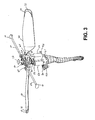
Figure 2 is an exploded view of the flying toy figurine shown inFigure 1 . -
Figure 3 , is a partially assembled view showing some of the internal drive components of one embodiment of the flying toy figurine. -
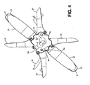
Figure 4 is a bottom view of one embodiment of the flying toy figurine. -
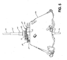
Figure 5 is a partially assembled view of the flying toy figurine showing the skirt portion, the drive gears, the gear plate, the top bearing, the center tube and the center shaft. -
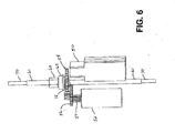
Figure 6 is a partially assembled view of the flying toy figurine showing the motor, the battery, the drive gears, the gear plate and the top bearing. - Various embodiments of the flying toy figurine will now be discussed in detail.
-
Figure 1 shows a front view of theflying toy figurine 1 including amain body 10. Themain body 10 has anupper body portion 12, alower body portion 14, and amiddle body portion 16. Theupper body portion 12 includes generally a head, arms and upper torso of thefigurine 1, and may be comprised of two or more sections that fit together, such as a front upper body portion 12a and a rear upper body portion 12b (see exploded view inFigure 2 ).Lower body portion 14 includes generally a lower part of the legs of thefigurine 1 and may be comprised of two or more sections that fit together, such as a frontlower body portion 14a and a rear lower body portion 14b (see exploded view inFigure 2 ). Themiddle body portion 16 includes awaist portion 18 and ahip portion 20. Thehip portion 20 includes askirt 22, askirt collar 24 fixed to the top of theskirt 22, and askirt bottom 25 fixed to the bottom of theskirt 22.Skirt collar 24 includesattachment pegs 27 that fit into holes in the top of theskirt 22 for attaching theskirt collar 24 to theskirt 22. -
Upper body portion 12 andlower body portion 14 are fixed together on acenter shaft 70 running longitudinally on a central axis A ofmain body 10.Center shaft 70 is secured at one end to anupper body fixer 72 and at the other end to a lower body fixer 74.Upper body portion 12 is affixed toupper body fixer 72, whilelower body portion 14 is affixed to lower body fixer 74.Center shaft 70 extends through acenter tube 61 that runs through themain body 10 centered on the central axis A. Centertube 61 is fixed tohip portion 20 for rotation therewith aboutcenter shaft 70.Center shaft 70 is free to rotate withincenter tube 61. As described below,waist portion 18 andhip portion 20 are mounted for independent rotation about central axis A, such rotation also being independent of the rotation ofupper body portion 12 andlower body portion 14, which are fixed together for synchronized rotation. - As shown in
Figures 1 and2 ,waist portion 18 ofmiddle body portion 16 includes arotor assembly 30, which provides aerodynamic lift to theflying toy figurine 1.Rotor assembly 30 includes two or moremain propeller blades 32, extending from thewaist portion 18.Main propeller blades 32 are attached to amain rotor pivot 62 bypropeller fixers 64, and may be hinged, as shown, so that when the propeller blades are not rotating they will fall to a somewhat more vertical position, thus providing the accoutrements of a skirt for the figurine. - Included in the
rotor assembly 30, and configured for synchronized rotation withmain propeller blades 32, arestabilizer bars 40 extending from thewaist portion 18, each stabilizer bar terminating in a bell-shaped stabilizer mass 42. Thestabilizer bars 40 are attached to amain rotor pivot 62 by astabilizer fixer 66, and may also be hinged, as shown inFigures 1 and2 , for the same purpose as indicated for themain propeller blades 32.Waist portion 18 is attached to thestabilizer fixer 66 bypins 19 on either side of the waist portion. - As shown in
Figures 1 and2 ,main propeller blades 32 may be equipped withprotective wire loops 33 surroundingouter tips 31 of the main propeller blades.Wire loops 33 have a round cross-section, are lightweight, and somewhat flexible. In the event themain propeller blades 32 come in contact with delicate human skin,wire loops 33 are designed to prevent the thin tip of the propeller blade from touching the skin. Thelightweight wire loops 33 have a negligible effect on performance of themain propeller blades 32. -
Hip portion 20 includes a set of two or more uniformly spacedsecondary propeller blades 34 attached to theskirt 22 and theskirt collar 24 and extending radially outward thereof.Secondary propeller blades 34, are not driven, but rather are allowed to spin freely with thehip portion 20 in a direction opposite to the direction of rotation of thewaist portion 18 and themain propeller blades 32 in response to rotational forces produced by rotation of themain propeller blades 32.Secondary propeller blades 34 may have a tear drop or petal shape as shown in the figures, so as to increase their surface area and provide some additional rotational resistance, thereby slowing their rotation and increasing the lift produced by themain propeller blades 32.Secondary propeller blades 34 may also be weighted on theirlower edges 35 to further increase rotational resistance and improve lift. In the embodiment shown inFigure 1 , the applicant has shown foursecondary propeller blades 34, however, it will be understood by those skilled in the area, that fewer or a greater number ofsecondary propeller blades 34 could be used. Thesecondary propeller blades 34 may be hinged to thehip portion 20 as shown inFigure 1 , so that when the secondary propeller blades are not rotating they will fall to a folded, somewhat more vertical position, thus providing the accoutrements of a skirt for the figurine. The bottom edges 35 oflower propeller blades 34 may be weighted to further assist the blades into the folded position and to provide additional rotational resistance, as mentioned above. - Contained internal of the
skirt 22 portion ofhip portion 20, and attached thereto, is abattery 50 for providing power to adrive motor 52, for providing motive force to therotor assembly 30. Both thebattery 50 and drivemotor 52 are electrically connected to a circuit board 80, which is fixed to theskirt bottom 25. Circuit board 80 includes an on-off switch 82, having aswitch cover 84. Also included on circuit board 80 is a chargingport 86 for connection to a charging unit for rechargingbattery 50. - As shown in
Figures 2 ,3 , and6 , thedrive motor 52 includes anoutput shaft 53 connected to apinion gear 54. A mainrotor drive gear 58 includes a mainrotor drive shaft 60.Pinion 54 is drivingly coupled to themain drive gear 58 and the mainrotor drive shaft 60 through acompound transmission gear 56 mounted to a post on the top ofskirt 22. Themain drive gear 58 sits for rotation on top of agear plate 75 located on top of acenter skirt tube 23 fixed to the top ofskirt 22.Gear plate 75, preferably made of metal, acts as a bearing to reduce friction between themain gear 58 and theskirt 22. - A
top bearing 63 is located onmain drive gear 58 centered on mainrotor drive shaft 60.Skirt collar 24 is fixed totop bearing 63 and is therefore free to rotate withtop bearing 63, independent of themain drive gear 58.Skirt collar 24 is fixed to skirt 22. The mainrotor drive shaft 60 extends through ahole 69 in the top ofskirt collar 24 and drivingly connects to themain rotor pivot 62, which is in turn connected tomain propeller blades 32 bypropeller fixers 64 that extend through slots in thewaist portion 18.Main rotor pivot 62 is further drivingly connected tostabilizers 40 by thestabilizer fixer 66 that extends through slots in thewaist portion 18. A linkage 68 connects one side of thestabilizer fixer 66 to one of thepropeller fixers 64. - Running
motor 52 causes rotation ofpinion gear 54, which engagestransmission gear 56 and causes rotation of themain drive gear 58 androtor shaft 60. Engagement of themain rotor shaft 60 with themain rotor pivot 62 causes rotation of themain rotor pivot 62. Engagement of themain rotor pivot 62 with thepropeller fixers 64 causes rotation of themain propeller blades 34, thereby providing lift to the flyingtoy figurine 1. Engagement of themain rotor pivot 62 with thestabilizer fixer 66 causes rotation ofstabilizers 40. Rotation ofstabilizers 40 is thereby synchronized with rotation of themain propeller blades 34. - Linkage 68 between
lower propeller fixer 64 andstabilizer fixer 66 is a common helicopter design that takes advantage of gyroscopic forces and is intended to stabilize thelower propeller blades 32 in windy conditions or if the flyingtoy figurine 1 encounters air flow from an air conditioner. - The freely rotating
center shaft 70 extends longitudinally throughcenter tube 61 that runs throughmain body 10 centered on the central axisA. Center tube 61 runs through and is fixed to theskirt tube 23 and therefore rotates withhip portion 20.Center tube 61 extends from the top of themain rotor pivot 62 to the skirt bottom 25, running through, but not fixed to, themain rotor pivot 62, themain drive gear 58, thegear plate 75, circuit board 80, andskirt bottom 25.Center shaft 70 therefore extends through the center ofmiddle body portion 16 and is independent of the rotation ofwaist portion 18, includingrotor assembly 30, andhip portion 20.Upper body portion 12 andlower body portion 14 are thus configured to remain stationary, independent of the rotation of thewaist portion 18, including themain propeller blades 32, and independent of the rotation of thehip portion 20, including thesecondary propeller blades 34. -
Secondary propellers 34 are connected to theskirt 22 and to theskirt collar 24 ofhip portion 20 for rotation therewith. When therotor assembly 30 is spinning,hip portion 20, including thesecondary propeller blades 34, spins ontop bearing 63 in the opposite direction ofpropeller blades 34, at a proportional rate, in response to counter-rotational torque produced by driving therotor assembly 30. In the absence of any restraint, the rate of rotation of thesecondary propeller blades 34 would leave little of the motor's torque available to provide lift. It is therefore desirable to slow the rate of rotation of the secondary blades to provide increased lift. This is accomplished by increasing drag produced by thesecondary propeller blades 34 by enlarging the size of the secondary propeller blades or by adding weight. Drag may also be increased by orienting the blades at an angle relative to the central axis "A" as shown inFigures 1 and2 . In this configuration, downwash from themain propeller blades 32 exerts a further anti-rotational force onsecondary propellers 34. - To control and maintain the height of the flying
toy figurine 1 at a pre-determined distance above a surface or object, a flight control system is provided. As shown inFigures 2 ,3 and4 , the flight control system includes circuitry on circuit board 80 which includes connections for communication with atransmitter 90 and a receiver 92 inserted though openings in theskirt bottom 25. The transmitter may be an infrared transmitter, such as an LED emitter, and the receiver may be an infrared receiver, however, other transmitter/receiver pairs may be used. During flight, thetransmitter 90 sends a flight control signal directed vertically downward and the receiver 92 and measures the strength of the reflection of the flight control signal from the ground or any surface or object that may be inserted between the ground and thetransmitter 90. Control circuits on circuit board 80 then adjust the power transmitted tomotor 52 to drive therotor assembly 30 either faster or slower, depending on the strength of the reflected flight control signal, to thereby maintain the predetermined height of the flyingtoy figurine 1 above the surface or object. If the strength of the reflected flight control signal received by the receiver 92 is less than a pre-determined value, it means that the flyingtoy figurine 1 is higher than the pre-determined distance above the surface or object and power tomotor 52 is reduced. If the strength of the reflected flight control signal received by the receiver 92 is greater than a pre-determined value, it means that the flyingtoy figurine 1 is lower than the pre-determined distance above the surface or object and power tomotor 52 is increased. - In a further embodiment, circuit board 80 may be fitted with a receiver to receive wireless control signals from a remote transmitter, such as radio frequency signals or infrared signals. The remote transmitter may be used to send and the receiver may be used to receive wireless control signals for turning the power on and off, and/or for controlling the amount of power sent to the
motor 52 to drive therotor assembly 30 at different speeds to thereby control the height of the flyingtoy figurine 1 above a surface or object. The above-described wireless remote control transmitter/receive combination may be used as an alternative to the above-described flight control system to control and maintain the height of the flyingtoy figurine 1 above a surface or object. - Included on circuit board 80 for safety purposes is a cutoff switch designed to cut power to the
rotor assembly 30 when electric current to thedrive motor 52 increases above a predetermined amount. If the main propeller blades encounter an obstacle such as a wall, the floor, or a person's hand, the current being sent to the motor will increase as the motor attempts to overcome the obstacle. If the current increases beyond a pre-determined limit, power to themotor 52 is cut and therotor assembly 30 stops. This is a safety feature design to prevent injury to the user. - To operate the flying
toy figurine 1, a user charges thebattery 50 by plugging chargingport 86 into a charging unit for a period of time until the battery is fully charged.Switch 82 is moved to the "on" position and the flyingtoy figurine 1 is oriented in a substantially vertical position, as shown inFigure 1 . At this point,motor 52 is activated, driving therotor assembly 30, providing lift and causing the flyingtoy figurine 1 to fly.Motor 52 may be activated by a wireless control signal sent by a remote transmitter, or the motor may turn on with movement of theswitch 82 to the "on" position. -
Rotor assembly 30, includingmain propeller blades 32, is driven bymotor 52 in one rotational direction. Counter-rotational torque produced by driving themain propeller blades 32 causeship portion 22, including thesecondary propeller blades 34 to spin ontop bearing 63 in the opposite rotational direction. Sincecenter shaft 70 runs freely throughcenter tube 61 and is not attached to either of thewaist portion 18, therotor assembly 30, or thehip portion 20,upper body portion 12 andlower body portion 14 will remain stationary. In reality, thecenter shaft 70 may turn slowly in one direction or the other, depending upon slight differences in rotational friction between the counter-rotating components that come in frictional contact withcenter shaft 70. These differences are due to the speed of rotation of the counter-rotating components, surface finish, lubrication and size tolerances. For example, as themain pivot 62 begins to rotate, it pushes up slightly and makes contact with the base of theupper body fixer 72 imparting some rotational force to thecenter shaft 70 in the direction of rotation of themain propeller blades 32. At the sametime center tube 61, which is fixed toskirt tube 23, begins to rotate with thehip portion 20 in the opposite direction due to the counter-rotational torque produce by driving themain propeller blades 32. Rotational frictional produced by contact betweencenter tube 61 andcenter shaft 70, will tend to causecenter shaft 70 to rotate in a direction opposite the direction of the rotation ofmain propeller blades 32. At times these two counter-rotational forces will balance, andupper body portion 12 andlower body portion 14 will remain stationary relative to themiddle body portion 16. At other times, one of the counter-rotational forces may be greater than the other, and the upper andlower body portions toy figurine 1, the direction of rotation may change due to changes in the counter-rotational forces. At all times, however,center shaft 70 remains independent of the rotation ofwaist portion 18 and thehip portion 20, and the rate of rotation of the upper andlower body portions main propeller blades 32 and thesecondary propeller blades 34. The stationary appearance, or slow rate of rotation of the upper andlower body portions secondary propeller blades - To control and maintain the height of the flying
toy figurine 1 at a pre-determined distance above a surface or object,transmitter 90 sends a flight control signal directed vertically downward and the receiver 92 measures the strength of the reflection of that signal from the ground or any surface or object that may be inserted between the ground and thetransmitter 90. Control circuits on circuit board 80 then adjust the power transmitted tomotor 52 to drive therotor assembly 30 either faster or slower, depending on the strength of the reflected signal, to thereby maintain the predetermined height of the flyingtoy figurine 1 above the surface or object. If the strength of the reflected signal received by the receiver 92 is less than a pre-determined value, it means that the flyingtoy figurine 1 is higher than the pre-determined distance above the surface or object and power tomotor 52 is reduced. If the strength of the reflected signal received by the receiver 92 is greater than a pre-determined value, it means that the flyingtoy figurine 1 is lower than the pre-determined distance above the surface or object and power tomotor 52 is increased. - The previous detailed description is provided to enable any person skilled in the art to make or use the present flying toy figurine. Various modifications to those embodiments will be readily apparent to those skilled in the art, and the generic principles defined herein may be applied to other embodiments without departing from the scope as defined by the appended claims. Thus, the present flying toy figurine is not intended to be limited to the embodiments shown herein, but is to be accorded the full scope consistent with the appended claims, wherein reference to an element in the singular, such as by use of the article "a" or "an" is not intended to mean "one and only one" unless specifically so stated, but rather "one or more".
Claims (15)
- A flying toy figurine(1) comprising:a main body(10), the main body comprising an upper body portion (12), a lower body portion (14) and a middle body portion (16), the middle body portion comprising a waist portion (18) and a hip portion (20);a center shaft (70) located on a central axis (A) of the main body (10), a first end of the center shaft being fixed to the upper body portion (12) and a second, opposite end of the center shaft being fixed to the lower body portion (14);a drive motor (52) for driving a rotor assembly (30), the rotor assembly including at least two main propeller blades (32) for providing aerodynamic lift to the flying toy figurine (1), the rotor assembly located in the waist portion (18);a source of power (50) for running the drive motor (52);a control system (80,90,92) for regulating the operation of the drive motor;wherein the waist portion (18) and the hip portion (20) are mounted for rotation about the center shaft (70), said rotation of the waist portion (18) and the hip portion (20) being independent of rotation of the center shaft (70);wherein running the drive motor (52) to drive the rotor assembly (30) and waist portion (18) in a first rotational direction imparts aerodynamic lift causing the flying toy figurine (1) to fly and further causing the hip portion to rotate in a second rotational direction opposite the first rotational direction; andwherein the center shaft (70) remains independent of the rotation of the waist portion (18) and the hip portion (20).
- The flying toy figurine of claim 1, wherein the drive motor is located in the hip portion.
- The flying toy figurine of claim 1 or 2, wherein the center shaft extends through a center tube (61) for rotation therein, the center tube being fixed to the hip portion.
- The flying toy figurine of any one of claims 1-3, wherein the main propeller blades (32) are hingably connected to the rotor assembly.
- The flying toy figurine of any one of claims 1-4, wherein the rotor assembly includes a pair of stabilizer bars (40) extending from the waist portion for rotation therewith.
- The flying toy figurine of any one of claims 1-5, wherein outer tips (31) of the main propeller blades include protective wire loops (33).
- The flying toy figurine of any one of claims 1-6, wherein the hip portion includes at least two secondary propeller blades (34) connected to and extending radially outward thereof.
- The flying toy figurine of claim 7, wherein the secondary propeller blades are hingably connected to the hip portion.
- The flying toy figurine of claim 7 or 8, wherein the secondary propeller blades are weighted along bottom edges thereof.
- The flying toy figurine of any one of claims 7-9, wherein secondary propeller blades are connected to the hip portion at an angle relative to the central axis.
- The flying toy figurine of any one of claims 1-10, wherein the control system includes a first transmitter (90) for transmitting flight control signals and a first receiver (92) for receiving the flight control signals after the flight control signals have reflected off of a surface, and control circuitry (80) for controlling and maintaining the height of the flying toy figurine above the surface by measuring the strength of the flight control signals reflected off of the surface and adjusting the amount of power transmitted to the motor relative to the strength of the reflected flight control signals.
- The flying toy figurine claim 11, wherein the control system includes a second receiver for receiving wireless flight control signals and a second remote transmitter for transmitting the wireless flight control signals, and where the control circuitry includes means for turning the motor on and off in response to the wireless control signals.
- The flying toy figurine of any one of claims 1-10, wherein the control system includes a receiver for receiving wireless control signals and a remote transmitter for transmitting the wireless control signals to the receiver, and control circuitry for turning the motor on and off and for controlling and maintaining the height of the flying toy figurine above a surface in response to the wireless control signals.
- The flying toy figurine of any one of claims 1-13, wherein the control system includes a motor cut-off switch to cut power to the drive motor when electric current to the drive motor increases above a predetermined amount.
- The flying toy figurine of any one of claims 1 to 14, wherein the waist portion (18) and the hip portion (20) are independently rotatable so that running the drive motor (52) to drive the rotor assembly (30) and waist portion (18) in the first rotational direction imparts a counter-rotational force to the hip portion (20) causing the hip portion (20) to rotate in the second rotational direction opposite the first rotational direction.
Priority Applications (1)
| Application Number | Priority Date | Filing Date | Title |
|---|---|---|---|
| PL13163293T PL2759323T3 (en) | 2013-02-08 | 2013-04-11 | Flying toy figurine |
Applications Claiming Priority (1)
| Application Number | Priority Date | Filing Date | Title |
|---|---|---|---|
| CA2804810A CA2804810C (en) | 2013-02-08 | 2013-02-08 | Flying toy figurine |
Publications (2)
| Publication Number | Publication Date |
|---|---|
| EP2759323A1 EP2759323A1 (en) | 2014-07-30 |
| EP2759323B1 true EP2759323B1 (en) | 2014-12-10 |
Family
ID=48092755
Family Applications (1)
| Application Number | Title | Priority Date | Filing Date |
|---|---|---|---|
| EP13163293.7A Active EP2759323B1 (en) | 2013-02-08 | 2013-04-11 | Flying toy figurine |
Country Status (6)
| Country | Link |
|---|---|
| US (1) | US9216363B2 (en) |
| EP (1) | EP2759323B1 (en) |
| CN (1) | CN203291506U (en) |
| CA (1) | CA2804810C (en) |
| ES (1) | ES2526899T3 (en) |
| PL (1) | PL2759323T3 (en) |
Families Citing this family (14)
| Publication number | Priority date | Publication date | Assignee | Title |
|---|---|---|---|---|
| CN203060813U (en) * | 2011-12-06 | 2013-07-17 | 余昕 | entertainment device |
| US20140349547A1 (en) * | 2012-12-08 | 2014-11-27 | Retail Authority LLC | Wirelessly controlled action figures |
| US9358474B2 (en) | 2013-06-21 | 2016-06-07 | Rehco, Llc | Flying toy doll assembly |
| CN104162278B (en) * | 2014-06-17 | 2016-08-17 | 廖明忠 | A kind of air suspension and the method for programmable movements, system and toy aircraft |
| US20160101368A1 (en) * | 2014-10-09 | 2016-04-14 | Rehco, Llc | Propeller and Frame Assemblies for Toys |
| CN105846755B (en) * | 2015-01-14 | 2019-04-19 | 南京德朔实业有限公司 | The control method of electric tool and motor |
| US10250792B2 (en) | 2015-08-10 | 2019-04-02 | Platypus IP PLLC | Unmanned aerial vehicles, videography, and control methods |
| USD798960S1 (en) * | 2015-08-19 | 2017-10-03 | Spin Master Ltd. | Flying toy unicorn |
| CN107050807A (en) * | 2017-04-18 | 2017-08-18 | 佛山市神风航空科技有限公司 | A kind of walk helper and its walk help mode |
| US10894219B1 (en) * | 2017-09-05 | 2021-01-19 | David Thomas Parker | Finger flying hover toy |
| JP6952140B2 (en) * | 2020-01-23 | 2021-10-20 | 株式会社バンダイ | Structure |
| US12138559B2 (en) | 2020-03-11 | 2024-11-12 | Spin Master Ltd. | System and method for controlling a flying toy |
| USD1065350S1 (en) * | 2023-06-07 | 2025-03-04 | Fairmount Investments Ltd. | Toy |
| CN222854588U (en) * | 2025-04-09 | 2025-05-13 | 汕头市剑指星空科技有限公司 | Toy aircraft |
Family Cites Families (24)
| Publication number | Priority date | Publication date | Assignee | Title |
|---|---|---|---|---|
| US447284A (en) * | 1891-02-24 | Eliseo del valle | ||
| US2397632A (en) * | 1941-03-04 | 1946-04-02 | Gen Motors Corp | Airplane |
| US2949693A (en) * | 1959-01-19 | 1960-08-23 | Wen Mac Corp | Flying toy |
| US3394906A (en) * | 1966-05-24 | 1968-07-30 | Rogers Lester | Flying saucer structure |
| US3479764A (en) * | 1967-04-19 | 1969-11-25 | Marvin Glass & Associates | Aerial toy |
| US3995392A (en) | 1975-01-21 | 1976-12-07 | Adolph E. Goldfarb | Toy flying vehicle set |
| US4065873A (en) * | 1976-08-30 | 1978-01-03 | Robert Alexander Jones | Flying saucer toy |
| US4531692A (en) * | 1982-03-15 | 1985-07-30 | Ernesto Mateus | Helicopter flight control and transmission system |
| US5525086A (en) | 1995-03-13 | 1996-06-11 | Gentile; John | Launchable figurine device |
| USD377058S (en) * | 1995-10-13 | 1996-12-31 | Lanard Toys Limited | Flying toy |
| US6042451A (en) * | 1998-08-14 | 2000-03-28 | Mattel, Inc. | Doll simulating ice skating or dancing spin moves |
| US8113905B2 (en) | 2001-03-28 | 2012-02-14 | Steven Davis | Directionally controllable flying vehicle and a propeller mechanism for accomplishing the same |
| US6843699B2 (en) * | 2001-03-28 | 2005-01-18 | Steven Davis | Flying toy |
| CN2530700Y (en) * | 2002-02-22 | 2003-01-15 | 谭念伯 | Flight toy using transmission case to power wings |
| US20040200924A1 (en) | 2003-01-29 | 2004-10-14 | Clark Leonard R. | Radio-controlled flying toy |
| KR100537173B1 (en) | 2003-06-21 | 2005-12-26 | 주식회사마이크로에어 | Micro Aerial Vehlcle |
| US7946526B2 (en) * | 2004-11-05 | 2011-05-24 | Nachman Zimet | Rotary-wing vehicle system |
| JP2006158612A (en) * | 2004-12-07 | 2006-06-22 | Taiyo Kogyo Kk | Flying toy |
| US7100866B2 (en) | 2005-01-14 | 2006-09-05 | Rehco, Llc | Control system for a flying vehicle |
| US8282437B2 (en) | 2005-07-22 | 2012-10-09 | Genie Toys Plc | Launchable dolls |
| US8187049B2 (en) * | 2007-02-07 | 2012-05-29 | Spin Master Ltd. | Transformable toy vehicle |
| CN101708369B (en) | 2009-12-04 | 2012-06-20 | 许岳煌 | Aircraft toy |
| US20140091942A1 (en) * | 2012-09-25 | 2014-04-03 | Asian Express Holdings Limited | Hovering Spinning Display |
| US8639400B1 (en) * | 2012-09-26 | 2014-01-28 | Silverlit Limited | Altitude control of an indoor flying toy |
-
2013
- 2013-02-08 CA CA2804810A patent/CA2804810C/en active Active
- 2013-04-11 PL PL13163293T patent/PL2759323T3/en unknown
- 2013-04-11 ES ES13163293.7T patent/ES2526899T3/en active Active
- 2013-04-11 EP EP13163293.7A patent/EP2759323B1/en active Active
- 2013-04-18 US US13/865,369 patent/US9216363B2/en active Active
- 2013-06-21 CN CN2013203613535U patent/CN203291506U/en not_active Expired - Lifetime
Also Published As
| Publication number | Publication date |
|---|---|
| US20140227932A1 (en) | 2014-08-14 |
| EP2759323A1 (en) | 2014-07-30 |
| CA2804810A1 (en) | 2013-04-16 |
| HK1195024A1 (en) | 2014-10-31 |
| ES2526899T3 (en) | 2015-01-16 |
| PL2759323T3 (en) | 2015-03-31 |
| US9216363B2 (en) | 2015-12-22 |
| CN203291506U (en) | 2013-11-20 |
| CA2804810C (en) | 2013-09-10 |
Similar Documents
| Publication | Publication Date | Title |
|---|---|---|
| CA2804810C (en) | Flying toy figurine | |
| US8308522B2 (en) | Flying toy | |
| CN101965217B (en) | Acrobatic rotary-wing toy helicopter | |
| US6659395B2 (en) | Propellers and propeller related vehicles | |
| KR100537173B1 (en) | Micro Aerial Vehlcle | |
| KR101200762B1 (en) | Remote-controlled fluttering object capable of flying forward in upright position | |
| JP2006158612A (en) | Flying toy | |
| EP2043914A1 (en) | Control system for a flying vehicle | |
| EP1688167B1 (en) | Model airplane | |
| GB2451718A (en) | Flying object wing | |
| US20050061909A1 (en) | Radio controlled helicopter | |
| CN102887224B (en) | Insect flapping wing simulating aircraft | |
| US2537393A (en) | Toy helicopter | |
| HK1195024B (en) | Flying toy figurine | |
| CN201101893Y (en) | Telecontrolled model helicopter | |
| JPH11509758A (en) | A toy airplane that can fly remotely in a closed area such as an indoor space | |
| CN110856772A (en) | Unpowered model | |
| USRE47176E1 (en) | Propellers and propeller related vehicles | |
| US3696822A (en) | Flying toy | |
| KR20220038249A (en) | closed wing-shaped radio-controlled paper model airplane | |
| KR200262006Y1 (en) | The Ornithopter Attached Slide Apparatus | |
| KR200352279Y1 (en) | Remote controllable flying toy | |
| CN103158872A (en) | Directed centrifugal force-driven rotating aircraft flight control principle and structure | |
| HK1160618B (en) | Flying toy | |
| HK1160618A1 (en) | Flying toy |
Legal Events
| Date | Code | Title | Description |
|---|---|---|---|
| PUAI | Public reference made under article 153(3) epc to a published international application that has entered the european phase |
Free format text: ORIGINAL CODE: 0009012 |
|
| 17P | Request for examination filed |
Effective date: 20130702 |
|
| AK | Designated contracting states |
Kind code of ref document: A1 Designated state(s): AL AT BE BG CH CY CZ DE DK EE ES FI FR GB GR HR HU IE IS IT LI LT LU LV MC MK MT NL NO PL PT RO RS SE SI SK SM TR |
|
| AX | Request for extension of the european patent |
Extension state: BA ME |
|
| GRAP | Despatch of communication of intention to grant a patent |
Free format text: ORIGINAL CODE: EPIDOSNIGR1 |
|
| GRAS | Grant fee paid |
Free format text: ORIGINAL CODE: EPIDOSNIGR3 |
|
| REG | Reference to a national code |
Ref country code: HK Ref legal event code: DE Ref document number: 1195024 Country of ref document: HK |
|
| INTG | Intention to grant announced |
Effective date: 20141008 |
|
| RIN1 | Information on inventor provided before grant (corrected) |
Inventor name: SULLIVAN, TIMOTHY MICHAEL |
|
| GRAA | (expected) grant |
Free format text: ORIGINAL CODE: 0009210 |
|
| AK | Designated contracting states |
Kind code of ref document: B1 Designated state(s): AL AT BE BG CH CY CZ DE DK EE ES FI FR GB GR HR HU IE IS IT LI LT LU LV MC MK MT NL NO PL PT RO RS SE SI SK SM TR |
|
| REG | Reference to a national code |
Ref country code: GB Ref legal event code: FG4D |
|
| REG | Reference to a national code |
Ref country code: CH Ref legal event code: EP |
|
| REG | Reference to a national code |
Ref country code: IE Ref legal event code: FG4D |
|
| REG | Reference to a national code |
Ref country code: AT Ref legal event code: REF Ref document number: 700353 Country of ref document: AT Kind code of ref document: T Effective date: 20150115 |
|
| REG | Reference to a national code |
Ref country code: ES Ref legal event code: FG2A Ref document number: 2526899 Country of ref document: ES Kind code of ref document: T3 Effective date: 20150116 |
|
| REG | Reference to a national code |
Ref country code: SE Ref legal event code: TRGR |
|
| REG | Reference to a national code |
Ref country code: DE Ref legal event code: R096 Ref document number: 602013000578 Country of ref document: DE Effective date: 20150122 |
|
| REG | Reference to a national code |
Ref country code: NL Ref legal event code: T3 |
|
| REG | Reference to a national code |
Ref country code: PL Ref legal event code: T3 |
|
| PG25 | Lapsed in a contracting state [announced via postgrant information from national office to epo] |
Ref country code: NO Free format text: LAPSE BECAUSE OF FAILURE TO SUBMIT A TRANSLATION OF THE DESCRIPTION OR TO PAY THE FEE WITHIN THE PRESCRIBED TIME-LIMIT Effective date: 20150310 Ref country code: FI Free format text: LAPSE BECAUSE OF FAILURE TO SUBMIT A TRANSLATION OF THE DESCRIPTION OR TO PAY THE FEE WITHIN THE PRESCRIBED TIME-LIMIT Effective date: 20141210 |
|
| PG25 | Lapsed in a contracting state [announced via postgrant information from national office to epo] |
Ref country code: GR Free format text: LAPSE BECAUSE OF FAILURE TO SUBMIT A TRANSLATION OF THE DESCRIPTION OR TO PAY THE FEE WITHIN THE PRESCRIBED TIME-LIMIT Effective date: 20150311 Ref country code: LV Free format text: LAPSE BECAUSE OF FAILURE TO SUBMIT A TRANSLATION OF THE DESCRIPTION OR TO PAY THE FEE WITHIN THE PRESCRIBED TIME-LIMIT Effective date: 20141210 Ref country code: RS Free format text: LAPSE BECAUSE OF FAILURE TO SUBMIT A TRANSLATION OF THE DESCRIPTION OR TO PAY THE FEE WITHIN THE PRESCRIBED TIME-LIMIT Effective date: 20141210 Ref country code: HR Free format text: LAPSE BECAUSE OF FAILURE TO SUBMIT A TRANSLATION OF THE DESCRIPTION OR TO PAY THE FEE WITHIN THE PRESCRIBED TIME-LIMIT Effective date: 20141210 |
|
| REG | Reference to a national code |
Ref country code: HK Ref legal event code: GR Ref document number: 1195024 Country of ref document: HK |
|
| PG25 | Lapsed in a contracting state [announced via postgrant information from national office to epo] |
Ref country code: CZ Free format text: LAPSE BECAUSE OF FAILURE TO SUBMIT A TRANSLATION OF THE DESCRIPTION OR TO PAY THE FEE WITHIN THE PRESCRIBED TIME-LIMIT Effective date: 20141210 Ref country code: SK Free format text: LAPSE BECAUSE OF FAILURE TO SUBMIT A TRANSLATION OF THE DESCRIPTION OR TO PAY THE FEE WITHIN THE PRESCRIBED TIME-LIMIT Effective date: 20141210 Ref country code: RO Free format text: LAPSE BECAUSE OF FAILURE TO SUBMIT A TRANSLATION OF THE DESCRIPTION OR TO PAY THE FEE WITHIN THE PRESCRIBED TIME-LIMIT Effective date: 20141210 Ref country code: EE Free format text: LAPSE BECAUSE OF FAILURE TO SUBMIT A TRANSLATION OF THE DESCRIPTION OR TO PAY THE FEE WITHIN THE PRESCRIBED TIME-LIMIT Effective date: 20141210 Ref country code: PT Free format text: LAPSE BECAUSE OF FAILURE TO SUBMIT A TRANSLATION OF THE DESCRIPTION OR TO PAY THE FEE WITHIN THE PRESCRIBED TIME-LIMIT Effective date: 20150410 |
|
| PG25 | Lapsed in a contracting state [announced via postgrant information from national office to epo] |
Ref country code: IS Free format text: LAPSE BECAUSE OF FAILURE TO SUBMIT A TRANSLATION OF THE DESCRIPTION OR TO PAY THE FEE WITHIN THE PRESCRIBED TIME-LIMIT Effective date: 20150410 |
|
| REG | Reference to a national code |
Ref country code: DE Ref legal event code: R097 Ref document number: 602013000578 Country of ref document: DE |
|
| PLBE | No opposition filed within time limit |
Free format text: ORIGINAL CODE: 0009261 |
|
| STAA | Information on the status of an ep patent application or granted ep patent |
Free format text: STATUS: NO OPPOSITION FILED WITHIN TIME LIMIT |
|
| PG25 | Lapsed in a contracting state [announced via postgrant information from national office to epo] |
Ref country code: DK Free format text: LAPSE BECAUSE OF FAILURE TO SUBMIT A TRANSLATION OF THE DESCRIPTION OR TO PAY THE FEE WITHIN THE PRESCRIBED TIME-LIMIT Effective date: 20141210 |
|
| 26N | No opposition filed |
Effective date: 20150911 |
|
| PG25 | Lapsed in a contracting state [announced via postgrant information from national office to epo] |
Ref country code: MC Free format text: LAPSE BECAUSE OF FAILURE TO SUBMIT A TRANSLATION OF THE DESCRIPTION OR TO PAY THE FEE WITHIN THE PRESCRIBED TIME-LIMIT Effective date: 20141210 Ref country code: LU Free format text: LAPSE BECAUSE OF FAILURE TO SUBMIT A TRANSLATION OF THE DESCRIPTION OR TO PAY THE FEE WITHIN THE PRESCRIBED TIME-LIMIT Effective date: 20150411 |
|
| REG | Reference to a national code |
Ref country code: IE Ref legal event code: MM4A |
|
| REG | Reference to a national code |
Ref country code: AT Ref legal event code: UEP Ref document number: 700353 Country of ref document: AT Kind code of ref document: T Effective date: 20141210 |
|
| PG25 | Lapsed in a contracting state [announced via postgrant information from national office to epo] |
Ref country code: SI Free format text: LAPSE BECAUSE OF FAILURE TO SUBMIT A TRANSLATION OF THE DESCRIPTION OR TO PAY THE FEE WITHIN THE PRESCRIBED TIME-LIMIT Effective date: 20141210 |
|
| REG | Reference to a national code |
Ref country code: FR Ref legal event code: PLFP Year of fee payment: 4 |
|
| PG25 | Lapsed in a contracting state [announced via postgrant information from national office to epo] |
Ref country code: IE Free format text: LAPSE BECAUSE OF NON-PAYMENT OF DUE FEES Effective date: 20150411 |
|
| REG | Reference to a national code |
Ref country code: DE Ref legal event code: R082 Ref document number: 602013000578 Country of ref document: DE Representative=s name: HERNANDEZ, YORCK, DIPL.-ING., DE |
|
| REG | Reference to a national code |
Ref country code: CH Ref legal event code: PL |
|
| PG25 | Lapsed in a contracting state [announced via postgrant information from national office to epo] |
Ref country code: MT Free format text: LAPSE BECAUSE OF FAILURE TO SUBMIT A TRANSLATION OF THE DESCRIPTION OR TO PAY THE FEE WITHIN THE PRESCRIBED TIME-LIMIT Effective date: 20141210 |
|
| PG25 | Lapsed in a contracting state [announced via postgrant information from national office to epo] |
Ref country code: CH Free format text: LAPSE BECAUSE OF NON-PAYMENT OF DUE FEES Effective date: 20160430 Ref country code: LI Free format text: LAPSE BECAUSE OF NON-PAYMENT OF DUE FEES Effective date: 20160430 |
|
| REG | Reference to a national code |
Ref country code: FR Ref legal event code: PLFP Year of fee payment: 5 |
|
| PG25 | Lapsed in a contracting state [announced via postgrant information from national office to epo] |
Ref country code: BG Free format text: LAPSE BECAUSE OF FAILURE TO SUBMIT A TRANSLATION OF THE DESCRIPTION OR TO PAY THE FEE WITHIN THE PRESCRIBED TIME-LIMIT Effective date: 20141210 Ref country code: HU Free format text: LAPSE BECAUSE OF FAILURE TO SUBMIT A TRANSLATION OF THE DESCRIPTION OR TO PAY THE FEE WITHIN THE PRESCRIBED TIME-LIMIT; INVALID AB INITIO Effective date: 20130411 |
|
| PG25 | Lapsed in a contracting state [announced via postgrant information from national office to epo] |
Ref country code: CY Free format text: LAPSE BECAUSE OF FAILURE TO SUBMIT A TRANSLATION OF THE DESCRIPTION OR TO PAY THE FEE WITHIN THE PRESCRIBED TIME-LIMIT Effective date: 20141210 |
|
| PG25 | Lapsed in a contracting state [announced via postgrant information from national office to epo] |
Ref country code: TR Free format text: LAPSE BECAUSE OF FAILURE TO SUBMIT A TRANSLATION OF THE DESCRIPTION OR TO PAY THE FEE WITHIN THE PRESCRIBED TIME-LIMIT Effective date: 20141210 |
|
| REG | Reference to a national code |
Ref country code: FR Ref legal event code: PLFP Year of fee payment: 6 |
|
| PG25 | Lapsed in a contracting state [announced via postgrant information from national office to epo] |
Ref country code: SM Free format text: LAPSE BECAUSE OF FAILURE TO SUBMIT A TRANSLATION OF THE DESCRIPTION OR TO PAY THE FEE WITHIN THE PRESCRIBED TIME-LIMIT Effective date: 20141210 |
|
| PG25 | Lapsed in a contracting state [announced via postgrant information from national office to epo] |
Ref country code: MK Free format text: LAPSE BECAUSE OF FAILURE TO SUBMIT A TRANSLATION OF THE DESCRIPTION OR TO PAY THE FEE WITHIN THE PRESCRIBED TIME-LIMIT Effective date: 20141210 |
|
| PG25 | Lapsed in a contracting state [announced via postgrant information from national office to epo] |
Ref country code: AL Free format text: LAPSE BECAUSE OF FAILURE TO SUBMIT A TRANSLATION OF THE DESCRIPTION OR TO PAY THE FEE WITHIN THE PRESCRIBED TIME-LIMIT Effective date: 20141210 |
|
| PGFP | Annual fee paid to national office [announced via postgrant information from national office to epo] |
Ref country code: SE Payment date: 20230321 Year of fee payment: 11 |
|
| P01 | Opt-out of the competence of the unified patent court (upc) registered |
Effective date: 20230530 |
|
| PGFP | Annual fee paid to national office [announced via postgrant information from national office to epo] |
Ref country code: LT Payment date: 20230408 Year of fee payment: 11 |
|
| PGFP | Annual fee paid to national office [announced via postgrant information from national office to epo] |
Ref country code: AT Payment date: 20230322 Year of fee payment: 11 |
|
| REG | Reference to a national code |
Ref country code: LT Ref legal event code: MM4D Effective date: 20240411 |
|
| REG | Reference to a national code |
Ref country code: SE Ref legal event code: EUG |
|
| REG | Reference to a national code |
Ref country code: AT Ref legal event code: MM01 Ref document number: 700353 Country of ref document: AT Kind code of ref document: T Effective date: 20240411 |
|
| PG25 | Lapsed in a contracting state [announced via postgrant information from national office to epo] |
Ref country code: LT Free format text: LAPSE BECAUSE OF NON-PAYMENT OF DUE FEES Effective date: 20240411 |
|
| PG25 | Lapsed in a contracting state [announced via postgrant information from national office to epo] |
Ref country code: AT Free format text: LAPSE BECAUSE OF NON-PAYMENT OF DUE FEES Effective date: 20240411 |
|
| PG25 | Lapsed in a contracting state [announced via postgrant information from national office to epo] |
Ref country code: LT Free format text: LAPSE BECAUSE OF NON-PAYMENT OF DUE FEES Effective date: 20240411 Ref country code: AT Free format text: LAPSE BECAUSE OF NON-PAYMENT OF DUE FEES Effective date: 20240411 |
|
| PGFP | Annual fee paid to national office [announced via postgrant information from national office to epo] |
Ref country code: DE Payment date: 20250319 Year of fee payment: 13 |
|
| PGFP | Annual fee paid to national office [announced via postgrant information from national office to epo] |
Ref country code: ES Payment date: 20250509 Year of fee payment: 13 |
|
| PG25 | Lapsed in a contracting state [announced via postgrant information from national office to epo] |
Ref country code: SE Free format text: LAPSE BECAUSE OF NON-PAYMENT OF DUE FEES Effective date: 20240412 |
|
| PGFP | Annual fee paid to national office [announced via postgrant information from national office to epo] |
Ref country code: GB Payment date: 20260324 Year of fee payment: 14 |
|
| PGFP | Annual fee paid to national office [announced via postgrant information from national office to epo] |
Ref country code: BE Payment date: 20260325 Year of fee payment: 14 Ref country code: IT Payment date: 20260325 Year of fee payment: 14 |
|
| PGFP | Annual fee paid to national office [announced via postgrant information from national office to epo] |
Ref country code: NL Payment date: 20260325 Year of fee payment: 14 |
|
| PGFP | Annual fee paid to national office [announced via postgrant information from national office to epo] |
Ref country code: FR Payment date: 20260324 Year of fee payment: 14 |
|
| PGFP | Annual fee paid to national office [announced via postgrant information from national office to epo] |
Ref country code: PL Payment date: 20260325 Year of fee payment: 14 |