EP2759279A1 - Anchoring device between cylinders and spacers of position keys for dental implants - Google Patents
Anchoring device between cylinders and spacers of position keys for dental implants Download PDFInfo
- Publication number
- EP2759279A1 EP2759279A1 EP13152447.2A EP13152447A EP2759279A1 EP 2759279 A1 EP2759279 A1 EP 2759279A1 EP 13152447 A EP13152447 A EP 13152447A EP 2759279 A1 EP2759279 A1 EP 2759279A1
- Authority
- EP
- European Patent Office
- Prior art keywords
- cylinders
- spacers
- ring
- spacer
- engaged
- Prior art date
- Legal status (The legal status is an assumption and is not a legal conclusion. Google has not performed a legal analysis and makes no representation as to the accuracy of the status listed.)
- Granted
Links
Images



Classifications
-
- A—HUMAN NECESSITIES
- A61—MEDICAL OR VETERINARY SCIENCE; HYGIENE
- A61C—DENTISTRY; APPARATUS OR METHODS FOR ORAL OR DENTAL HYGIENE
- A61C13/00—Dental prostheses; Making same
- A61C13/12—Tools for fastening artificial teeth; Holders, clamps, or stands for artificial teeth
-
- A—HUMAN NECESSITIES
- A61—MEDICAL OR VETERINARY SCIENCE; HYGIENE
- A61C—DENTISTRY; APPARATUS OR METHODS FOR ORAL OR DENTAL HYGIENE
- A61C8/00—Means to be fixed to the jaw-bone for consolidating natural teeth or for fixing dental prostheses thereon; Dental implants; Implanting tools
- A61C8/0001—Impression means for implants, e.g. impression coping
-
- A—HUMAN NECESSITIES
- A61—MEDICAL OR VETERINARY SCIENCE; HYGIENE
- A61C—DENTISTRY; APPARATUS OR METHODS FOR ORAL OR DENTAL HYGIENE
- A61C8/00—Means to be fixed to the jaw-bone for consolidating natural teeth or for fixing dental prostheses thereon; Dental implants; Implanting tools
- A61C8/0048—Connecting the upper structure to the implant, e.g. bridging bars
Definitions
- the single spacer is held in position on the cylinder it must sustain, by the fingers of the operator who is compelled to manually keep the spacer in its correct operating position for the whole time necessary for anchoring it onto the body of the cylinder. It is evident, however, that this operation is not only laborious, but also difficult to complete satisfactorily, as the spaces available in the patient's mouth and small dimensions of the spacers and cylinders hinder the accurate implementation of this coupling.
- the anchoring device between cylinders and spacers of position keys of dental implants composed of cylinders and spacers, characterized in that it is equipped with means suitable for temporarily holding said cylinders and spacers in their relative position, corresponding to that of the dental implant.
- the device of the invention consists of an elastically deformable metal wire, on which at least two folds are formed, reciprocally joined by means of a corresponding portion of wire.
- the invention extends to the position key for dental implants provided with the above anchoring device.
- the elasticity of the plastic material used for producing the device 3 is advantageously such as to allow dimensional and shape variations between the above-mentioned rings 4 and 5 to be compensated, in relation to the cylinders 1 and spacers 2.
- the same rings 4, 5 have an axial cut 7, which allows them to be enlarged and, in this way, exert a retention force on the outer surface of the respective cylinders and spacers.
Landscapes
- Health & Medical Sciences (AREA)
- Oral & Maxillofacial Surgery (AREA)
- Dentistry (AREA)
- Epidemiology (AREA)
- Life Sciences & Earth Sciences (AREA)
- Animal Behavior & Ethology (AREA)
- General Health & Medical Sciences (AREA)
- Public Health (AREA)
- Veterinary Medicine (AREA)
- Orthopedic Medicine & Surgery (AREA)
- Prostheses (AREA)
- Dental Prosthetics (AREA)
Abstract
Description
- The present invention relates to a device suitable for the temporary anchorage between cylinders and spacers of keys used in the positioning of dental implants.
- The field of invention relates to equipment used for transferring, on a model, the position of dental implants situated in a patient's mouth in order to effect the fixing of the superstructures.
- In this type of application, the problem arises of maintaining the original position of dental implants to be transferred to the operating model, as positioned inside the patient's mouth. For this purpose, spacers are used, which are anchored, at the head or in correspondence with their ends, to the respective cylinders that reproduce the position of the implants on the key. The relative fixing between spacers and cylinders is obtained with the use of composite or gypsum-based materials, whose function is to firmly anchor the head of the spacer onto the body of the respective cylinder.
- At present, the single spacer is held in position on the cylinder it must sustain, by the fingers of the operator who is compelled to manually keep the spacer in its correct operating position for the whole time necessary for anchoring it onto the body of the cylinder. It is evident, however, that this operation is not only laborious, but also difficult to complete satisfactorily, as the spaces available in the patient's mouth and small dimensions of the spacers and cylinders hinder the accurate implementation of this coupling.
- In addition, there are also difficulties due to the fact that the operator always has one hand engaged for holding the spacer in position, at least until it has been firmly anchored to the body of the cylinders of the implant.
- An objective of the invention is to provide a device suitable for simplifying the relative positioning operations described between spacers and cylinders, also effectively contributing to the anchoring precision and thus avoiding inaccuracies, responsible for undesired positioning errors of the original implant when it is transferred to the operating model.
- A further objective of the invention is to hold the spacers in the patient's mouth without requiring the manual intervention of the operator.
- These and other objectives are achieved with the anchoring device between cylinders and spacers of position keys of dental implants composed of cylinders and spacers, characterized in that it is equipped with means suitable for temporarily holding said cylinders and spacers in their relative position, corresponding to that of the dental implant.
- According to a preferred embodiment, the device of the invention is also characterized in that said means consist of a first ring, destined for being engaged on the body of said cylinder, in addition to at least a second ring which is engaged on a first spacer of the position key and joined to the previous ring by means of a bar.
- In accordance with the invention, said means also comprise a third ring suitable for being engaged on a second spacer of the above-mentioned position key, with a bar for joining said third ring to the above-mentioned first ring, the latter assembled on said cylinder. The same rings of the device of the invention also have an axial cut, suitable for favouring their insertion on the body of the spacers and cylinders of the position key.
- According to a further variant, the device of the invention consists of an elastically deformable metal wire, on which at least two folds are formed, reciprocally joined by means of a corresponding portion of wire.
- In accordance with a further variant, the device of the invention consists of an elastically deformable metal wire, on which there is a third fold, joined to the adjacent fold by means of a corresponding portion of wire.
- The invention extends to the position key for dental implants provided with the above anchoring device.
- With respect to the systems used in the known art, the device of the invention offers the advantage of being able to be pre-assembled on the spacer, with a rapid and simple operation effected outside the patient's mouth. The device of the invention is then also fixed to the respective cylinder situated in the oral cavity with equally rapid and simple operations, thus providing a temporary anchorage which holds the cylinders of the implant and spacers forming the position key, in the correct relative position.
- A further advantage lies in the fact that the device of the invention maintains the reciprocal positioning between the cylinders and spacers for the whole time necessary for effecting the definitive anchorage of the position key, without having to resort to additional manual interventions for this purpose.
- Furthermore, thanks to the invention, the operator can easily complete the positioning of the position key in the mouth, correcting any possible coupling errors between cylinders and spacers before proceeding with their reciprocal definitive fixing.
- These and other objectives, advantages and characteristics will appear evident from the following description of some preferred embodiments of the device of the invention shown, for purely illustrative and non-limiting purposes, in the figures of the enclosed drawings, in which:
-
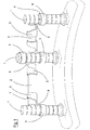
figure 1 is a perspective view, lingual or palatal side, of a position key for dental implants, provided with the device of the invention; -
figure 2 is a perspective view, labial side, of a position key provided with a variant of the device of the invention; -
figures 3 and 4 illustrate the device of the invention, as used on the key offigure 1 , in a front and side view respectively; -
figures 5 and 6 , illustrate a variant of the device of the invention, as assembled on the key offigure 2 ; -
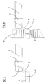
figures 7 and 8 illustrate assembly phases of the device offigures 3 and 4 on the key offigure 1 ; -
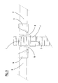
figure 9 illustrates the detail of the device offigures 5 and 6 , as anchored on the central cylinder and on the spacers of the key offigure 2 ; -
figures 10 to 12 illustrate further variants of the device of the invention. - The position key illustrated in
figures 1 and2 is composed of a plurality of cylinders 1, which exert the function of defining the position, in the patient's mouth, of the respective implants and reproducing, on an operating model, their position thus defined. - In order to sustain the cylinders 1 between each other, maintaining their correct relative positioning on the operating model, these are fixed to
respective spacers 2, arranged transversally with respect to the longitudinal axis of the same cylinders 1 and anchored at the head to the body of the same. - In order to maintain the temporary relative positioning between these
elements 1 and 2 before being definitively fixed (effected by means of suitable composite or gypsum-based materials), use is made of the device of the invention, indicated as a whole with 3 infigures 3 and 4 . In particular, thedevice 3 consists of a body made of a single piece of non-rigid plastic material, which comprises afirst ring 4 and asecond ring 5, reciprocally joined by aflexible bar 6. - The elasticity of the plastic material used for producing the
device 3 is advantageously such as to allow dimensional and shape variations between the above-mentionedrings spacers 2. For the same purpose, i.e. for favouring the deformation of therings same rings axial cut 7, which allows them to be enlarged and, in this way, exert a retention force on the outer surface of the respective cylinders and spacers. - In the variant of
figures 5 and 6 , in addition to the above-mentionedrings device 8 of the invention also has athird ring 9, equipped with a respectiveflexible fixing bar 10 to thering 4 which supports the cylinder 1 of the key offigure 2 . - When in use, the
device 3 offigures 1 ,3 and 4 is pre-assembled on thespacer 2, outside the patient's mouth, by inserting itssecond ring 5 onto the respective end of the same spacer 2 (figure 7 ). When ananalogous device 3 is assembled, in the same way, on the remaining end of the spacer, this is positioned inside the patient's mouth and anchored to the cylinder 1 by means of thefirst ring 4 remaining free (figure 8 ). The temporary reciprocal anchorage between cylinder 1 and the respective end of thespacer 2 is therefore ensured by theabove rings bar 6. The flexible nature of this bar allows the correct orientation of the spacers on the cylinders, whereas thecut 7, which is present on thesame rings - Once the position key has been thus pre-assembled in the patient's mouth, the definitive fixing of the spacers to the cylinders is effected by immersion of the same, together with the
temporary anchoring devices 3, in a depth of polymeric material, which subsequently hardens for the purpose. - With analogous operations to those described above, the variant of the
device 8 offigures 2 ,5 ,6 and9 is anchored with itsring 4 to the central cylinder 1 and with theremaining rings respective spacers 2. Finally, therespective bars - In the variant of
figures 10 and 11 , the device of the invention is substantially produced starting from an elastically deformed metal wire (such as, for example, the metal wire of a spring). There are two substantially "U"-shaped folds reference number 14 offigure 10 , whereas in the version illustrated infigure 11 , thedevice 15 of the invention has threefolds - The nature of the
above devices wire folds - As represented in
figure 12 , the assembly of thedevice 14 of the invention on the respective key is effected by hooking, by elastic deformation, itsfolds spacer 2 andcorresponding side cylinder 1a, respectively. - The hooking onto the
central cylinder 1b of the position key can, on the other hand, be effected by utilizing thecentral fold 12 of thedevice 15 offigure 11 , theremaining end folds side spacers 2. - The key prepared in this way also has a sufficient rigidity for allowing it to be transferred onto the respective model, the original position of the implant being ensured by the pre-assembly described above, effected with the device of the invention, and subsequently by the grip of the polymeric material that ensures the definitive solidification of the structure thus obtained.
- Having thus described some preferred exemplary embodiments of the device of the present invention in accordance with the principles of the present invention it should be apparent to those skilled in the art that various additional objects and advantages have been attained by the invention and that a variety of modifications can be made within the scope of the present invention, being limited by the following appended claims only.
Claims (9)
- A temporary anchoring device between cylinders and spacers of position keys for dental implants composed of cylinders (1) and spacers (2), characterized in that it is equipped with means suitable for temporarily holding said cylinders (1) and the mentioned spacers (2) in their relative position, corresponding to that of the dental implant.
- The device according to claim 1, characterized in that said means consist of a first ring (4) destined for being engaged on the body of said cylinder (1), and at least a second ring (5) which is engaged on a first spacer (2) of the position key and joined to the previous ring (4) by means of a bar (6).
- The device according to claim 2, characterized in that said means also comprise a third ring (9) suitable for being engaged on a second spacer (2) of the above-mentioned position key, there also being a bar (10) for joining said third ring (9) to the mentioned first ring (4), the latter assembled on said cylinder (1).
- The anchoring device according to claims 2 and 3, characterized in that said rings (4,5,9) are equipped with an axial cut (7).
- The device according to one or more of the previous claims, characterized in that it is made of a flexible material.
- The device according to claim 1, characterized in that it consists of an elastically deformable metal wire, on which at least two folds (11, 12) are formed, reciprocally joined by means of a corresponding portion of wire (16).
- The device according to claim 6, characterized in that said wire made of an elastically deformable material also has a third fold (13), joined to the adjacent fold (12) by means of a corresponding portion of wire (17).
- The device according to claims 6 and 7, characterized in that said folds (11,12,13) are substantially "U"-shaped.
- A position key for dental implants, characterized in that it is equipped with a device according to one or more of the previous claims.
Priority Applications (2)
| Application Number | Priority Date | Filing Date | Title |
|---|---|---|---|
| EP13152447.2A EP2759279B1 (en) | 2013-01-24 | 2013-01-24 | Anchoring device between cylinders and spacers of position keys for dental implants |
| PCT/EP2013/003845 WO2014114316A1 (en) | 2013-01-24 | 2013-12-17 | Anchoring device between cylinders and spacers of position keys for dental implants |
Applications Claiming Priority (1)
| Application Number | Priority Date | Filing Date | Title |
|---|---|---|---|
| EP13152447.2A EP2759279B1 (en) | 2013-01-24 | 2013-01-24 | Anchoring device between cylinders and spacers of position keys for dental implants |
Publications (2)
| Publication Number | Publication Date |
|---|---|
| EP2759279A1 true EP2759279A1 (en) | 2014-07-30 |
| EP2759279B1 EP2759279B1 (en) | 2018-01-24 |
Family
ID=47713854
Family Applications (1)
| Application Number | Title | Priority Date | Filing Date |
|---|---|---|---|
| EP13152447.2A Active EP2759279B1 (en) | 2013-01-24 | 2013-01-24 | Anchoring device between cylinders and spacers of position keys for dental implants |
Country Status (2)
| Country | Link |
|---|---|
| EP (1) | EP2759279B1 (en) |
| WO (1) | WO2014114316A1 (en) |
Cited By (1)
| Publication number | Priority date | Publication date | Assignee | Title |
|---|---|---|---|---|
| IT201700050645A1 (en) * | 2017-05-10 | 2018-11-10 | Laser Tech Di Lusuardi Giorgio | BAR STRUCTURE FOR DENTAL PROSTHESIS. |
Citations (9)
| Publication number | Priority date | Publication date | Assignee | Title |
|---|---|---|---|---|
| US4260383A (en) * | 1979-08-27 | 1981-04-07 | Ipco Hospital Supply Corporation | Dental retaining splint |
| WO2002062257A1 (en) * | 2001-02-05 | 2002-08-15 | Accius B.V. | Fastening device for an orthesis or prosthesis |
| US20040018469A1 (en) * | 2002-07-23 | 2004-01-29 | Robert Summers | Impression support system for dental implants |
| US20040142300A1 (en) * | 2003-01-21 | 2004-07-22 | Aravena Ines Monica | Multi-adjustable drill guide and framework system for dental prosthetics |
| WO2006038877A1 (en) * | 2004-10-07 | 2006-04-13 | Dan Lundgren Ab | A prosthetic structure and a method for producing prosthetic structure |
| EP1712199A2 (en) * | 2005-04-11 | 2006-10-18 | Putzer, Philip, Dr. | Implant system for an immediatly loadable implantological care of the jaw |
| WO2008044919A2 (en) * | 2006-10-10 | 2008-04-17 | Mark Johannes Hubertus Verdoes | An assembly comprising at least one fixing device to be attached to an implant |
| WO2011040977A1 (en) * | 2009-10-01 | 2011-04-07 | Ototronix, Llc | Improved middle ear implant and method |
| EP2481371A1 (en) * | 2009-09-23 | 2012-08-01 | Rinês De Freitas Iglesias | Bar articulated in three planes for use in dental implants |
-
2013
- 2013-01-24 EP EP13152447.2A patent/EP2759279B1/en active Active
- 2013-12-17 WO PCT/EP2013/003845 patent/WO2014114316A1/en not_active Ceased
Patent Citations (9)
| Publication number | Priority date | Publication date | Assignee | Title |
|---|---|---|---|---|
| US4260383A (en) * | 1979-08-27 | 1981-04-07 | Ipco Hospital Supply Corporation | Dental retaining splint |
| WO2002062257A1 (en) * | 2001-02-05 | 2002-08-15 | Accius B.V. | Fastening device for an orthesis or prosthesis |
| US20040018469A1 (en) * | 2002-07-23 | 2004-01-29 | Robert Summers | Impression support system for dental implants |
| US20040142300A1 (en) * | 2003-01-21 | 2004-07-22 | Aravena Ines Monica | Multi-adjustable drill guide and framework system for dental prosthetics |
| WO2006038877A1 (en) * | 2004-10-07 | 2006-04-13 | Dan Lundgren Ab | A prosthetic structure and a method for producing prosthetic structure |
| EP1712199A2 (en) * | 2005-04-11 | 2006-10-18 | Putzer, Philip, Dr. | Implant system for an immediatly loadable implantological care of the jaw |
| WO2008044919A2 (en) * | 2006-10-10 | 2008-04-17 | Mark Johannes Hubertus Verdoes | An assembly comprising at least one fixing device to be attached to an implant |
| EP2481371A1 (en) * | 2009-09-23 | 2012-08-01 | Rinês De Freitas Iglesias | Bar articulated in three planes for use in dental implants |
| WO2011040977A1 (en) * | 2009-10-01 | 2011-04-07 | Ototronix, Llc | Improved middle ear implant and method |
Cited By (1)
| Publication number | Priority date | Publication date | Assignee | Title |
|---|---|---|---|---|
| IT201700050645A1 (en) * | 2017-05-10 | 2018-11-10 | Laser Tech Di Lusuardi Giorgio | BAR STRUCTURE FOR DENTAL PROSTHESIS. |
Also Published As
| Publication number | Publication date |
|---|---|
| EP2759279B1 (en) | 2018-01-24 |
| WO2014114316A1 (en) | 2014-07-31 |
Similar Documents
| Publication | Publication Date | Title |
|---|---|---|
| JP2013506481A (en) | Orthodontic arc wire integrated with components that apply force to the teeth | |
| US10828133B2 (en) | Indirect orthodontic bonding systems and methods for bracket placement | |
| ES2849423T3 (en) | Device for correcting misalignments of teeth and procedure for fabricating an arch element for such a device | |
| KR101658318B1 (en) | orthodontic archwire with variable cross sectional configuration | |
| US20130196279A1 (en) | Individualized jig for orthodontic braces, assembly formed by that jig, a base and a bracket, and its design methods | |
| KR101978890B1 (en) | Transparent orthodontic device | |
| US7976308B2 (en) | Dental wedges and methods | |
| KR102512893B1 (en) | tooth moving device | |
| CA3027088C (en) | Orthodontic correction device | |
| US20090286200A1 (en) | Separating ring | |
| EP2759279A1 (en) | Anchoring device between cylinders and spacers of position keys for dental implants | |
| US20090104581A1 (en) | Dental Restoration Device | |
| US6890174B2 (en) | Anchor implanting device for orthodontics | |
| EP3009100B1 (en) | Kit and method for forming dental models | |
| US9655696B2 (en) | Kit and method for taking dental impressions and forming dental models | |
| KR102103890B1 (en) | Method for manufacturing indirect bonding tray for dental, indirect bonding tray manufactured by the same, and simulator for producing virtual guide | |
| US3626593A (en) | Orthodontic bracket | |
| US20220183796A1 (en) | Method for manufacturing a fitting device for an orthodontic apparatus | |
| US20190076219A1 (en) | Orthodontic bracket | |
| KR102875973B1 (en) | Orthodontic screws and dental orthopedic screws, and orthodontic appliances and dental orthopedic appliances | |
| US20210298873A1 (en) | Dental restoration system | |
| CN104323793B (en) | Positioning measuring device for orthodontic implant surgery | |
| KR20200022119A (en) | Abutment and implant for orthodontics | |
| EP3656342B1 (en) | Dental splint | |
| JP2005192989A (en) | Orthodontic bracket |
Legal Events
| Date | Code | Title | Description |
|---|---|---|---|
| PUAI | Public reference made under article 153(3) epc to a published international application that has entered the european phase |
Free format text: ORIGINAL CODE: 0009012 |
|
| 17P | Request for examination filed |
Effective date: 20130211 |
|
| AK | Designated contracting states |
Kind code of ref document: A1 Designated state(s): AL AT BE BG CH CY CZ DE DK EE ES FI FR GB GR HR HU IE IS IT LI LT LU LV MC MK MT NL NO PL PT RO RS SE SI SK SM TR |
|
| AX | Request for extension of the european patent |
Extension state: BA ME |
|
| 17Q | First examination report despatched |
Effective date: 20160229 |
|
| RIC1 | Information provided on ipc code assigned before grant |
Ipc: A61C 8/00 20060101ALN20170614BHEP Ipc: A61C 13/12 20060101AFI20170614BHEP |
|
| RIC1 | Information provided on ipc code assigned before grant |
Ipc: A61C 8/00 20060101ALN20170627BHEP Ipc: A61C 13/12 20060101AFI20170627BHEP |
|
| RIC1 | Information provided on ipc code assigned before grant |
Ipc: A61C 8/00 20060101ALN20170721BHEP Ipc: A61C 13/12 20060101AFI20170721BHEP |
|
| RIC1 | Information provided on ipc code assigned before grant |
Ipc: A61C 13/12 20060101AFI20170803BHEP Ipc: A61C 8/00 20060101ALN20170803BHEP |
|
| GRAP | Despatch of communication of intention to grant a patent |
Free format text: ORIGINAL CODE: EPIDOSNIGR1 |
|
| RAP1 | Party data changed (applicant data changed or rights of an application transferred) |
Owner name: KULZER GMBH |
|
| INTG | Intention to grant announced |
Effective date: 20170908 |
|
| GRAS | Grant fee paid |
Free format text: ORIGINAL CODE: EPIDOSNIGR3 |
|
| GRAA | (expected) grant |
Free format text: ORIGINAL CODE: 0009210 |
|
| AK | Designated contracting states |
Kind code of ref document: B1 Designated state(s): AL AT BE BG CH CY CZ DE DK EE ES FI FR GB GR HR HU IE IS IT LI LT LU LV MC MK MT NL NO PL PT RO RS SE SI SK SM TR |
|
| REG | Reference to a national code |
Ref country code: GB Ref legal event code: FG4D |
|
| REG | Reference to a national code |
Ref country code: CH Ref legal event code: EP |
|
| REG | Reference to a national code |
Ref country code: AT Ref legal event code: REF Ref document number: 965328 Country of ref document: AT Kind code of ref document: T Effective date: 20180215 |
|
| REG | Reference to a national code |
Ref country code: IE Ref legal event code: FG4D |
|
| REG | Reference to a national code |
Ref country code: DE Ref legal event code: R096 Ref document number: 602013032461 Country of ref document: DE |
|
| REG | Reference to a national code |
Ref country code: SE Ref legal event code: TRGR |
|
| REG | Reference to a national code |
Ref country code: NL Ref legal event code: MP Effective date: 20180124 |
|
| REG | Reference to a national code |
Ref country code: LT Ref legal event code: MG4D |
|
| REG | Reference to a national code |
Ref country code: AT Ref legal event code: MK05 Ref document number: 965328 Country of ref document: AT Kind code of ref document: T Effective date: 20180124 |
|
| PG25 | Lapsed in a contracting state [announced via postgrant information from national office to epo] |
Ref country code: NL Free format text: LAPSE BECAUSE OF FAILURE TO SUBMIT A TRANSLATION OF THE DESCRIPTION OR TO PAY THE FEE WITHIN THE PRESCRIBED TIME-LIMIT Effective date: 20180124 |
|
| PG25 | Lapsed in a contracting state [announced via postgrant information from national office to epo] |
Ref country code: ES Free format text: LAPSE BECAUSE OF FAILURE TO SUBMIT A TRANSLATION OF THE DESCRIPTION OR TO PAY THE FEE WITHIN THE PRESCRIBED TIME-LIMIT Effective date: 20180124 Ref country code: LT Free format text: LAPSE BECAUSE OF FAILURE TO SUBMIT A TRANSLATION OF THE DESCRIPTION OR TO PAY THE FEE WITHIN THE PRESCRIBED TIME-LIMIT Effective date: 20180124 Ref country code: NO Free format text: LAPSE BECAUSE OF FAILURE TO SUBMIT A TRANSLATION OF THE DESCRIPTION OR TO PAY THE FEE WITHIN THE PRESCRIBED TIME-LIMIT Effective date: 20180424 Ref country code: HR Free format text: LAPSE BECAUSE OF FAILURE TO SUBMIT A TRANSLATION OF THE DESCRIPTION OR TO PAY THE FEE WITHIN THE PRESCRIBED TIME-LIMIT Effective date: 20180124 Ref country code: CY Free format text: LAPSE BECAUSE OF FAILURE TO SUBMIT A TRANSLATION OF THE DESCRIPTION OR TO PAY THE FEE WITHIN THE PRESCRIBED TIME-LIMIT Effective date: 20180124 Ref country code: FI Free format text: LAPSE BECAUSE OF FAILURE TO SUBMIT A TRANSLATION OF THE DESCRIPTION OR TO PAY THE FEE WITHIN THE PRESCRIBED TIME-LIMIT Effective date: 20180124 |
|
| PG25 | Lapsed in a contracting state [announced via postgrant information from national office to epo] |
Ref country code: IS Free format text: LAPSE BECAUSE OF FAILURE TO SUBMIT A TRANSLATION OF THE DESCRIPTION OR TO PAY THE FEE WITHIN THE PRESCRIBED TIME-LIMIT Effective date: 20180524 Ref country code: GR Free format text: LAPSE BECAUSE OF FAILURE TO SUBMIT A TRANSLATION OF THE DESCRIPTION OR TO PAY THE FEE WITHIN THE PRESCRIBED TIME-LIMIT Effective date: 20180425 Ref country code: RS Free format text: LAPSE BECAUSE OF FAILURE TO SUBMIT A TRANSLATION OF THE DESCRIPTION OR TO PAY THE FEE WITHIN THE PRESCRIBED TIME-LIMIT Effective date: 20180124 Ref country code: PL Free format text: LAPSE BECAUSE OF FAILURE TO SUBMIT A TRANSLATION OF THE DESCRIPTION OR TO PAY THE FEE WITHIN THE PRESCRIBED TIME-LIMIT Effective date: 20180124 Ref country code: LV Free format text: LAPSE BECAUSE OF FAILURE TO SUBMIT A TRANSLATION OF THE DESCRIPTION OR TO PAY THE FEE WITHIN THE PRESCRIBED TIME-LIMIT Effective date: 20180124 Ref country code: AT Free format text: LAPSE BECAUSE OF FAILURE TO SUBMIT A TRANSLATION OF THE DESCRIPTION OR TO PAY THE FEE WITHIN THE PRESCRIBED TIME-LIMIT Effective date: 20180124 Ref country code: BG Free format text: LAPSE BECAUSE OF FAILURE TO SUBMIT A TRANSLATION OF THE DESCRIPTION OR TO PAY THE FEE WITHIN THE PRESCRIBED TIME-LIMIT Effective date: 20180424 |
|
| REG | Reference to a national code |
Ref country code: CH Ref legal event code: PL |
|
| REG | Reference to a national code |
Ref country code: DE Ref legal event code: R097 Ref document number: 602013032461 Country of ref document: DE |
|
| PG25 | Lapsed in a contracting state [announced via postgrant information from national office to epo] |
Ref country code: LU Free format text: LAPSE BECAUSE OF NON-PAYMENT OF DUE FEES Effective date: 20180124 Ref country code: MC Free format text: LAPSE BECAUSE OF FAILURE TO SUBMIT A TRANSLATION OF THE DESCRIPTION OR TO PAY THE FEE WITHIN THE PRESCRIBED TIME-LIMIT Effective date: 20180124 Ref country code: AL Free format text: LAPSE BECAUSE OF FAILURE TO SUBMIT A TRANSLATION OF THE DESCRIPTION OR TO PAY THE FEE WITHIN THE PRESCRIBED TIME-LIMIT Effective date: 20180124 Ref country code: EE Free format text: LAPSE BECAUSE OF FAILURE TO SUBMIT A TRANSLATION OF THE DESCRIPTION OR TO PAY THE FEE WITHIN THE PRESCRIBED TIME-LIMIT Effective date: 20180124 Ref country code: RO Free format text: LAPSE BECAUSE OF FAILURE TO SUBMIT A TRANSLATION OF THE DESCRIPTION OR TO PAY THE FEE WITHIN THE PRESCRIBED TIME-LIMIT Effective date: 20180124 |
|
| REG | Reference to a national code |
Ref country code: IE Ref legal event code: MM4A |
|
| REG | Reference to a national code |
Ref country code: BE Ref legal event code: MM Effective date: 20180131 |
|
| PG25 | Lapsed in a contracting state [announced via postgrant information from national office to epo] |
Ref country code: DK Free format text: LAPSE BECAUSE OF FAILURE TO SUBMIT A TRANSLATION OF THE DESCRIPTION OR TO PAY THE FEE WITHIN THE PRESCRIBED TIME-LIMIT Effective date: 20180124 Ref country code: SM Free format text: LAPSE BECAUSE OF FAILURE TO SUBMIT A TRANSLATION OF THE DESCRIPTION OR TO PAY THE FEE WITHIN THE PRESCRIBED TIME-LIMIT Effective date: 20180124 Ref country code: CZ Free format text: LAPSE BECAUSE OF FAILURE TO SUBMIT A TRANSLATION OF THE DESCRIPTION OR TO PAY THE FEE WITHIN THE PRESCRIBED TIME-LIMIT Effective date: 20180124 Ref country code: BE Free format text: LAPSE BECAUSE OF NON-PAYMENT OF DUE FEES Effective date: 20180131 Ref country code: LI Free format text: LAPSE BECAUSE OF NON-PAYMENT OF DUE FEES Effective date: 20180131 Ref country code: CH Free format text: LAPSE BECAUSE OF NON-PAYMENT OF DUE FEES Effective date: 20180131 Ref country code: SK Free format text: LAPSE BECAUSE OF FAILURE TO SUBMIT A TRANSLATION OF THE DESCRIPTION OR TO PAY THE FEE WITHIN THE PRESCRIBED TIME-LIMIT Effective date: 20180124 |
|
| PLBE | No opposition filed within time limit |
Free format text: ORIGINAL CODE: 0009261 |
|
| STAA | Information on the status of an ep patent application or granted ep patent |
Free format text: STATUS: NO OPPOSITION FILED WITHIN TIME LIMIT |
|
| GBPC | Gb: european patent ceased through non-payment of renewal fee |
Effective date: 20180424 |
|
| 26N | No opposition filed |
Effective date: 20181025 |
|
| PG25 | Lapsed in a contracting state [announced via postgrant information from national office to epo] |
Ref country code: IE Free format text: LAPSE BECAUSE OF NON-PAYMENT OF DUE FEES Effective date: 20180124 |
|
| PG25 | Lapsed in a contracting state [announced via postgrant information from national office to epo] |
Ref country code: GB Free format text: LAPSE BECAUSE OF NON-PAYMENT OF DUE FEES Effective date: 20180424 Ref country code: SI Free format text: LAPSE BECAUSE OF FAILURE TO SUBMIT A TRANSLATION OF THE DESCRIPTION OR TO PAY THE FEE WITHIN THE PRESCRIBED TIME-LIMIT Effective date: 20180124 |
|
| PG25 | Lapsed in a contracting state [announced via postgrant information from national office to epo] |
Ref country code: FR Free format text: LAPSE BECAUSE OF NON-PAYMENT OF DUE FEES Effective date: 20180324 |
|
| PG25 | Lapsed in a contracting state [announced via postgrant information from national office to epo] |
Ref country code: MT Free format text: LAPSE BECAUSE OF NON-PAYMENT OF DUE FEES Effective date: 20180124 |
|
| PG25 | Lapsed in a contracting state [announced via postgrant information from national office to epo] |
Ref country code: TR Free format text: LAPSE BECAUSE OF FAILURE TO SUBMIT A TRANSLATION OF THE DESCRIPTION OR TO PAY THE FEE WITHIN THE PRESCRIBED TIME-LIMIT Effective date: 20180124 |
|
| PGFP | Annual fee paid to national office [announced via postgrant information from national office to epo] |
Ref country code: IT Payment date: 20200131 Year of fee payment: 8 Ref country code: SE Payment date: 20200121 Year of fee payment: 8 |
|
| PG25 | Lapsed in a contracting state [announced via postgrant information from national office to epo] |
Ref country code: HU Free format text: LAPSE BECAUSE OF FAILURE TO SUBMIT A TRANSLATION OF THE DESCRIPTION OR TO PAY THE FEE WITHIN THE PRESCRIBED TIME-LIMIT; INVALID AB INITIO Effective date: 20130124 Ref country code: PT Free format text: LAPSE BECAUSE OF FAILURE TO SUBMIT A TRANSLATION OF THE DESCRIPTION OR TO PAY THE FEE WITHIN THE PRESCRIBED TIME-LIMIT Effective date: 20180124 |
|
| PG25 | Lapsed in a contracting state [announced via postgrant information from national office to epo] |
Ref country code: MK Free format text: LAPSE BECAUSE OF NON-PAYMENT OF DUE FEES Effective date: 20180124 |
|
| REG | Reference to a national code |
Ref country code: SE Ref legal event code: EUG |
|
| PG25 | Lapsed in a contracting state [announced via postgrant information from national office to epo] |
Ref country code: SE Free format text: LAPSE BECAUSE OF NON-PAYMENT OF DUE FEES Effective date: 20210125 |
|
| PG25 | Lapsed in a contracting state [announced via postgrant information from national office to epo] |
Ref country code: IT Free format text: LAPSE BECAUSE OF NON-PAYMENT OF DUE FEES Effective date: 20210124 |
|
| P01 | Opt-out of the competence of the unified patent court (upc) registered |
Effective date: 20230518 |
|
| PGFP | Annual fee paid to national office [announced via postgrant information from national office to epo] |
Ref country code: DE Payment date: 20260121 Year of fee payment: 14 |