EP2759004B1 - Battery mounting structure - Google Patents
Battery mounting structure Download PDFInfo
- Publication number
- EP2759004B1 EP2759004B1 EP12773373.1A EP12773373A EP2759004B1 EP 2759004 B1 EP2759004 B1 EP 2759004B1 EP 12773373 A EP12773373 A EP 12773373A EP 2759004 B1 EP2759004 B1 EP 2759004B1
- Authority
- EP
- European Patent Office
- Prior art keywords
- battery
- rod
- front wall
- ribs
- contact
- Prior art date
- Legal status (The legal status is an assumption and is not a legal conclusion. Google has not performed a legal analysis and makes no representation as to the accuracy of the status listed.)
- Active
Links
Images


Classifications
-
- B—PERFORMING OPERATIONS; TRANSPORTING
- B60—VEHICLES IN GENERAL
- B60R—VEHICLES, VEHICLE FITTINGS, OR VEHICLE PARTS, NOT OTHERWISE PROVIDED FOR
- B60R16/00—Electric or fluid circuits specially adapted for vehicles and not otherwise provided for; Arrangement of elements of electric or fluid circuits specially adapted for vehicles and not otherwise provided for
- B60R16/02—Electric or fluid circuits specially adapted for vehicles and not otherwise provided for; Arrangement of elements of electric or fluid circuits specially adapted for vehicles and not otherwise provided for electric constitutive elements
- B60R16/04—Arrangement of batteries
-
- H—ELECTRICITY
- H01—ELECTRIC ELEMENTS
- H01M—PROCESSES OR MEANS, e.g. BATTERIES, FOR THE DIRECT CONVERSION OF CHEMICAL ENERGY INTO ELECTRICAL ENERGY
- H01M50/00—Constructional details or processes of manufacture of the non-active parts of electrochemical cells other than fuel cells, e.g. hybrid cells
- H01M50/20—Mountings; Secondary casings or frames; Racks, modules or packs; Suspension devices; Shock absorbers; Transport or carrying devices; Holders
- H01M50/249—Mountings; Secondary casings or frames; Racks, modules or packs; Suspension devices; Shock absorbers; Transport or carrying devices; Holders specially adapted for aircraft or vehicles, e.g. cars or trains
-
- B—PERFORMING OPERATIONS; TRANSPORTING
- B60—VEHICLES IN GENERAL
- B60L—PROPULSION OF ELECTRICALLY-PROPELLED VEHICLES; SUPPLYING ELECTRIC POWER FOR AUXILIARY EQUIPMENT OF ELECTRICALLY-PROPELLED VEHICLES; ELECTRODYNAMIC BRAKE SYSTEMS FOR VEHICLES IN GENERAL; MAGNETIC SUSPENSION OR LEVITATION FOR VEHICLES; MONITORING OPERATING VARIABLES OF ELECTRICALLY-PROPELLED VEHICLES; ELECTRIC SAFETY DEVICES FOR ELECTRICALLY-PROPELLED VEHICLES
- B60L50/00—Electric propulsion with power supplied within the vehicle
- B60L50/50—Electric propulsion with power supplied within the vehicle using propulsion power supplied by batteries or fuel cells
- B60L50/60—Electric propulsion with power supplied within the vehicle using propulsion power supplied by batteries or fuel cells using power supplied by batteries
- B60L50/64—Constructional details of batteries specially adapted for electric vehicles
-
- H—ELECTRICITY
- H01—ELECTRIC ELEMENTS
- H01M—PROCESSES OR MEANS, e.g. BATTERIES, FOR THE DIRECT CONVERSION OF CHEMICAL ENERGY INTO ELECTRICAL ENERGY
- H01M50/00—Constructional details or processes of manufacture of the non-active parts of electrochemical cells other than fuel cells, e.g. hybrid cells
- H01M50/50—Current conducting connections for cells or batteries
- H01M50/572—Means for preventing undesired use or discharge
- H01M50/574—Devices or arrangements for the interruption of current
- H01M50/579—Devices or arrangements for the interruption of current in response to shock
-
- Y—GENERAL TAGGING OF NEW TECHNOLOGICAL DEVELOPMENTS; GENERAL TAGGING OF CROSS-SECTIONAL TECHNOLOGIES SPANNING OVER SEVERAL SECTIONS OF THE IPC; TECHNICAL SUBJECTS COVERED BY FORMER USPC CROSS-REFERENCE ART COLLECTIONS [XRACs] AND DIGESTS
- Y02—TECHNOLOGIES OR APPLICATIONS FOR MITIGATION OR ADAPTATION AGAINST CLIMATE CHANGE
- Y02E—REDUCTION OF GREENHOUSE GAS [GHG] EMISSIONS, RELATED TO ENERGY GENERATION, TRANSMISSION OR DISTRIBUTION
- Y02E60/00—Enabling technologies; Technologies with a potential or indirect contribution to GHG emissions mitigation
- Y02E60/10—Energy storage using batteries
-
- Y—GENERAL TAGGING OF NEW TECHNOLOGICAL DEVELOPMENTS; GENERAL TAGGING OF CROSS-SECTIONAL TECHNOLOGIES SPANNING OVER SEVERAL SECTIONS OF THE IPC; TECHNICAL SUBJECTS COVERED BY FORMER USPC CROSS-REFERENCE ART COLLECTIONS [XRACs] AND DIGESTS
- Y02—TECHNOLOGIES OR APPLICATIONS FOR MITIGATION OR ADAPTATION AGAINST CLIMATE CHANGE
- Y02T—CLIMATE CHANGE MITIGATION TECHNOLOGIES RELATED TO TRANSPORTATION
- Y02T10/00—Road transport of goods or passengers
- Y02T10/60—Other road transportation technologies with climate change mitigation effect
- Y02T10/70—Energy storage systems for electromobility, e.g. batteries
Definitions
- the invention relates to battery mounting structure.
- Japanese Patent Application Publication No. 2003-118395 JP 2003-118395 A describes a battery mounting structure that prevents a battery from being damaged due to interference with a front rod that attaches the battery when the battery moves forward from inertia due to an impact from the front of a vehicle.
- the front rod is able to rotate relative to a battery bracket that retains the battery. Therefore, space for the front rod to rotate must be ensured on the front side in the vehicle longitudinal direction.
- Japanese Patent Application Publication No. 2002-225750 JP 2002-225750 A
- JP 2004-142593 JP 2004-142593 A
- Japanese Patent Application Publications No. 2004-262413 JPS61180454U and JPH02134653U also describe battery mounting structures.
- the invention provides two battery mounting structures respectively defined by independent claims 1 and 7, said structures being capable of inhibiting interference between a battery and a rod caused by inertia force acting on the battery when a frontal collision occurs, without limiting the battery arrangement.
- One aspect of the invention relates to a battery mounting structure that includes a battery bracket that is fixed to a body of a vehicle, and on which a battery is mounted; a rod that is connected to the battery bracket in a state in which a gap is provided between the rod and a front wall of the battery, and that fixes the battery to the battery bracket; and an interference inhibiting portion that is provided between the rod and the front wall of the battery, and that inhibits interference between the battery and the rod by the front wall of the battery contacting the interference inhibiting portion when forward inertia force toward a front of the vehicle acts on the battery.
- the battery bracket on which the battery is mounted is fixed to the body of the vehicle.
- a rod is connected to the battery bracket, and this rod is connected to the battery bracket in a state in which a gap is provided between it (i.e., the rod) and the front wall of the battery.
- the battery is fixed to the battery bracket in this state.
- an interference inhibiting portion that inhibits interference between the battery and the rod is provided between the rod and the front wall of the battery.
- This interference inhibiting portion is designed so that the front wall of the battery will come into contact with it when forward inertia force acts on the battery. Therefore, it is possible to inhibit interference between the battery and the rod, and thus inhibit the battery from being damaged due to interference with the rod.
- the term "inhibit” in this case is intended to also include a case in which there is no interference between the front wall of the battery and the rod.
- the structure is not one that moves the rod in order to inhibit interference between it (i.e., the rod) and the battery, so the arrangement of the battery is not restricted, e.g., it is not necessary to ensure space to move the rod.
- the aspect described above has the beneficial effect of interference between the battery and the rod due to inertia acting on the battery when a frontal collision occurs being able to be inhibited.
- the interference inhibiting portion may be a contact portion that is fixed to the battery bracket and formed on a tray on which the battery is mounted, and that the front wall of the battery is able to come into contact with.
- the tray on which the battery is mounted is fixed to the battery bracket.
- the interference inhibiting portion is a contact portion that is formed on the tray, and the front wall of the battery is able to come into contact with this contact portion when forward inertia force toward the front of the vehicle acts on the battery. That is, here, the contact portion is formed on the tray, so a mounting structure can be realized that has the beneficial effect of being able to inhibit interference between the battery and the rod by a simpler structure than one in which the tray is formed separate from the contact portion and then joined to the tray by welding or adhesion or the like.
- a mounting structure that has a beneficial effect is able to be realized by a simple structure in which a contact portion is simply formed on a tray.
- the tray may be made of resin
- a flange portion may be provided standing erect on a peripheral edge portion of the tray that is plate-shaped, and the contact portion extends toward a front wall of the battery.
- Said contact portion may be a plurality of ribs that extend toward the front wall of the battery from an inside wall surface of the flange portion, and are provided at intervals in a width direction of the battery.
- the peripheral edge portion of the tray is surrounded by the flange portion, so even if the battery were to leak battery fluid, the leaked battery fluid would be able to be collected by the tray.
- the plurality of ribs extend toward the front wall of the battery from the inside wall surface of the flange portion, and are provided at intervals in a width direction of the battery.
- the front wall of the battery is able to contact these ribs.
- the ribs extend toward the front wall side of the battery from the inside wall surface of the flange of the tray, the ribs will not become undercut portions during mold release in a mold that forms the tray, so the ribs and the tray are able to be integrally formed.
- the battery mounting structure having this structure has the beneficial effects of inhibiting interference between the battery and the rod, being able to absorb impact energy from a frontal collision of the vehicle, and being able to have the tray and the contact portion be integrally formed.
- the rod may be a J-bolt, and one end portion of the J-bolt may be retained in a hole formed in the battery bracket that is made of metal.
- the J-bolt is made of metal.
- the hole may be damaged by axial force acting on the J-bolt when the other end portion of the J-bolt is fastened to the fixing plate.
- the hole is formed in the metal battery bracket and the one end portion of the J-bolt is retained in this hole, so this kind of problem is inhibited.
- the battery mounting structure having this structure has the beneficial effect of good assemblability compared with a case in which one end portion of the rod is fastened to the battery bracket in a narrow space, because one end portion of the J-bolt is simply hooked onto the battery bracket using the J-bolt as the rod.
- the interference inhibiting portion may be a contact piece that is welded to the rod, and that the front wall of the battery is able to come into contact with.
- the interference inhibiting portion is a contact piece that is welded to the rod.
- the front wall of the battery is able to come into contact with this contact piece when forward inertia force toward the front of the vehicle acts on the battery. That is, this structure inhibits interference between the battery and the rod.
- the battery mounting structure having this structure has the beneficial effect of a conventional part being able to be used as it is for the rod, because the contact piece is simply welded to the rod.
- the contact piece may be arranged with a gap between the rod and the contact piece, and may include an abutting surface portion that the front wall of the battery is able to come into contact with, and a pair of mounting leg portions that support the abutting surface portion, and end portions of which are welded to the rod.
- the abutting surface portion is provided on the contact piece, and the front wall of the battery is able to come into contact with this abutting surface portion when forward inertia force toward the front of the vehicle acts on the battery. That is, this structure inhibits interference between the battery and the rod.
- the abutting surface portion is supported, in a state arranged with a gap between it and the rod, by the pair of mounting leg portions with the end portions that are welded to the rod. Therefore, if forward inertia force toward the front of the vehicle acts on the battery as a result of a frontal collision of the vehicle, and the abutting surface portion is consequently pushed on while the front wall of the battery is contacting the abutting surface portion, the mounting leg portions will deform (i.e., elastically deform and plastic deform), and impact energy from the frontal collision of the vehicle will be absorbed. In this way, a stroke for absorbing the impact load can be ensured by providing the gap between the abutting surface portion and the rod.
- the battery mounting structure according to this structure has the beneficial effects of inhibiting interference between the battery and the rod, and absorbing impact energy from a frontal collision of the vehicle.
- arrow FR indicates a direction toward the front of the vehicle
- arrow UP indicates an upward direction with respect to the vehicle.
- front and rear will refer to the front and rear, respectively, in the vehicle longitudinal direction
- up or upper and down or lower will refer to the upper and lower directions, respectively, in the vehicle vertical direction.
- FIG. 1 is a perspective view, as viewed diagonally from the front and above at an angle, of a tray 38 and a battery 10 and the like to which the battery mounting structure according to this example embodiment has been applied.
- FIG. 2 is a sectional view taken along line II - II in FIG. 1
- FIG. 3 is an enlarged sectional view of portion A shown in FIG. 2 .
- the battery 10 is formed in a generally rectangular parallelepiped shape, and is retained by a battery bracket 12 that is made of sheet metal.
- the battery bracket 12 forms a mount 14.
- the sectional shape of this mount 14 is a rectangular wavy shape that is open downward.
- the battery 10 is mounted onto this mount 14 (this will be described later).
- the battery 10 is not necessarily arranged such that a side wall 11 thereof extends in a vehicle width direction or a vehicle longitudinal direction, but for the sake of simplifying the description, it will be described as being arranged with the side wall 11 thereof extending in the vehicle longitudinal direction.
- An attaching piece 16 is provided on a front end portion of the mount 14, and an attaching piece 18 is provided on a rear end portion of the mount 14.
- a clamp 20 is fixed to this attaching piece 18 in a position corresponding to a center portion, in the vehicle width direction, of the battery 10 that is mounted onto the mount 14.
- the clamp 20 is made of generally rectangular-shaped sheet metal and is fixed to the attaching piece 18 by welding or the like. Also, the clamp 20 is arranged extending in the vehicle height direction of the battery 10, and an end portion (a lower end portion) of a rear rod 22 is fixed to an upper end portion of the clamp 20 by welding or the like.
- a hole 16A is provided in the attaching piece 16 in a position corresponding to a center portion, in the vehicle width direction, of the battery 10 that is mounted onto the mount 14.
- a hook portion 24A that is provided on one end portion (a lower end portion) of a J-bolt 24 (rod) is inserted into this hole 16A. With this hook portion 24A inserted into the hole 16A, the hook portion 24A catches on an inside edge portion of the hole 16A and is thus retained.
- a fixing plate 26 that is formed in a rectangular shape is arranged extending in the vehicle longitudinal direction, on an upper surface of the battery 10.
- a movement restricting piece 28 that has a generally L-shaped cross-section is provided on both end sides of the fixing plate 26 in the longitudinal direction. These movement restricting pieces 28 restrict movement of a predetermined value or more of the battery 10 in the vehicle longitudinal direction.
- a through-hole 26A is formed in a rear end portion of the fixing plate 26.
- the other end portion of the rear rod 22 that is fixed to the upper end portion of the clamp 20 is inserted into this through-hole 26A.
- a nut 30 is fastened onto the other end portion of the rear rod 22.
- a through-hole 26B is formed in a front end portion of the fixing plate 26.
- the other end (i.e., the upper end portion) of the J-bolt 24 is able to be inserted into this through-hole 26B.
- the nut 30 is fastened onto the other end portion of the rear rod 22
- the other end portion of the J-bolt 24 is inserted into the through-hole 26B and a nut 32 is then fastened onto the other end portion of the J-bolt 24.
- the battery 10 is held to the mount 14 in a state sandwiched between the fixing plate 26 and the mount 14 (i.e., the battery bracket 12) via the J-bolt 24 and the rear rod 22.
- a fixing piece 34 that has a generally L-shaped cross-section is fixed to the front side of the mount 14 by welding or the like.
- a fastening portion 36 is provided on this fixing piece 34, and a bolt, not shown, is able to be fastened by this fastening portion 36.
- the battery bracket 12 is fixed to a body side, not shown, via this bolt.
- FIG. 4 is a perspective view of the tray 38 viewed diagonally from the front and above at an angle.
- the tray 38 has a generally rectangular shape, and a flange portion 39 that stands erect rising upward is formed on a peripheral edge portion of the tray 38.
- This flange portion 39 is provided extending along in the vehicle width direction and in the vehicle longitudinal direction.
- an outer dimension of a side wall 11 of the battery 10 is set to be slightly smaller than an inner dimension between flange portions 39 that are arranged opposite one another. Therefore, when the battery 10 is mounted on the tray 38, there is a gap between a front wall 11A of the battery 10 and the flange portion 39 of the tray 38.
- FIG. 5 is a plan view of the tray 38.
- ribs (contact portions) 40 that serve as an interference inhibiting portion extend toward the rear from an inside wall of the center portion, in the vehicle width direction, of a flange portion 39A arranged on the front side.
- These ribs 40 have generally rectangular shapes and are provided in plurality (five in this case) in the vehicle width direction (forming a rib group 41).
- the rib 40 positioned in the center of this rib group 41 is arranged on a straight line P that connects the location of the center of gravity O of the battery 10 with the J-bolt 24.
- the ribs 40 are formed parallel to one another.
- the extension length of the ribs 40 is set such that a gap is provided between tip end surfaces 40A of the ribs 40 and the front wall 11 A of the battery 10. Further, the height of the ribs 40 is set to approximately two times the height of the flange portion 39A in this case.
- inclined walls 42 are provided at base portions (i.e., portions of the flange portion 39A) of the ribs 40 that are arranged on the outside in the vehicle width direction, from among the plurality of ribs 40 that are provided. Upper end surfaces of the base portions of the ribs 40 are connected to an upper end surface of the flange portion 39A by the inclined walls 42.
- a gap H is provided between the J-bolt 24 and the front wall 11A of the battery 10 while the battery 10 is fixed sandwiched between the fixing plate 26 and the mount 14.
- the plurality of ribs 40 i.e., the rib group 41
- the rib group 41 extend toward the rear from the inside wall of the center portion, in the vehicle width direction, of the flange portion 39A arranged on the front side of the tray 38.
- the ribs 40 and the flange portion 39A of the tray 38 are arranged between the J-bolt 24 and the front wall 11 A of the battery 10.
- this inertia force will simply be referred to as "forward inertia force"
- the front wall 11 A of the battery 10 comes into surface contact with the tip end surfaces 40A of the plurality of ribs 40.
- the ribs 40 were not provided on the tray 38, for example, only the flange portion 39A of the tray 38 would be arranged between the J-bolt 24 and the front wall 11A of the battery 10 (this case is not shown). Therefore, when forward inertia force is applied (i.e., in the direction of arrow A) to the battery 10 as a result of a frontal collision of the vehicle or the like, the front wall 11A of the battery 10 comes into surface contact with the flange portion 39A of the tray 38.
- the battery 10 would ride over the tray 38 along the inclined surface of the inclined flange portion 39A, and the front wall 11A of the battery 10 may end up interfering (i.e., colliding) with the J-bolt 24.
- the plurality of ribs 40 are provided on the inside wall of the flange portion 39A that is arranged on the front side of the tray 38, so the strength of the tray 38 itself is able to be increased. As a result, deformation of the tray is inhibited, so the flange portion 39A is able to be prevented from slanting. That is, when forward inertia force acts on the battery 10, the battery 10 moves forward (i.e., in the direction of arrow A). However, the ribs 40 extend toward the rear from the inside wall of the flange portion 39A, so the front wall 11 A of the battery 10 comes into surface contact with the tip end surfaces 40A of the plurality of ribs 40.
- the structure is not one that moves the J-bolt 24 in order to inhibit interference between the battery 10 and the J-bolt 24, so the arrangement of the battery 10 is not restricted, e.g., it is not necessary to ensure space to move the J-bolt 24.
- interference between the battery 10 and the J-bolt 24 due to inertia of the battery 10 is able to be inhibited without the arrangement of the battery 10 being restricted by restrictions such as those described above.
- the term "inhibit” in this case is intended to also include a case in which there is no interference between the front wall 11A of the battery 10 and the J-bolt 24.
- the peripheral edge portion of the tray 38 is surrounded by the flange portions 39, so even if the battery 10 were to leak battery fluid, the leaked battery fluid would be able to be collected by the tray 38.
- the ribs 40 that serve as the interference inhibiting portion are formed on the inside wall surface of the flange portion 39A that is positioned on the front side of the tray 38. Accordingly, when forward inertia force acts on the battery 10 as a result of a frontal collision of the vehicle, the front wall 11A of the battery 10 comes into surface contact with the tip end surfaces 40A of the ribs 40, and the ribs 40 deform (i.e., elastically deform and plastic deform). The impact energy from the frontal collision of the vehicle is able to be absorbed by this deformation of the ribs 40. The amount of impact energy that is absorbed can be adjusted according to the height and width and the like of the ribs 40.
- the height of the ribs 40 is approximately two times the height of the flange portion 39A, but the height of the ribs 40 may also be equal to the height of the flange portion 39A or higher than the height of the flange portion 39A.
- the rib 40 that is positioned in the center of the rib group 41 is arranged on the straight line P that connects the location of the center of gravity O of the battery 10 with the J-bolt 24, and the ribs 40 are formed parallel to one another. That is, these ribs 40 are arranged in the direction in which the battery 10 will move, so impact energy from a frontal collision of the vehicle is able to be efficiently absorbed.
- interference between the battery 10 and the J-bolt 24 is able to be inhibited by forming the ribs 40 on the tray 38, and thus is able to be realized by a simpler structure than one in which the contact portion that the front wall 11A of the battery 10 comes into surface contact with is formed separate from the tray 38 and then joined to the tray 38 by welding or adhesion or the like.
- the ribs 40 extend toward the front wall 11 A side of the battery 10 from the inside wall surface of the flange portion 39A of the tray 38. Therefore, the ribs 40 will not become undercut portions during mold release in a mold that forms the tray 38, so the ribs 40 and the tray 38 are able to be integrally formed.
- the J-bolt 24 is made of metal.
- a hole not shown, is provided in the resin tray 38, and the hook portion 24A that is positioned on one end portion of the J-bolt 24 is hooked into this hole.
- the hole 16A is provided in the attaching piece 16 that is provided on the battery bracket 12 made of sheet metal, and the hook portion 24A of the J-bolt 24 is retained in this hole 16A. Therefore, this kind of problem is inhibited.
- the hook portion 24A of the J-bolt 24 is simply hooked into the hole 16A when attaching the battery 10, so assemblability is better than it is when fastening one end portion of the rod to the battery bracket in a narrow space, which is not shown.
- a rod other than the J-bolt 24 may of course also be used.
- the plurality of ribs 40 are provided in the center portion, in the vehicle width direction, of the flange portion 39A that is positioned on the front side of the tray 38.
- the ribs 40 are provided in positions opposite to the J-bolt 24.
- this rib group 41 is not limited to being in the center portion of the flange portion 39A in the vehicle width direction.
- rib groups 45 each of which is formed by a plurality of ribs 44, may also be arranged one on each side, in the vehicle width direction, of the rib group 41 that is arranged in the center portions, in the vehicle width direction, of the flange portion 39A, in a manner sandwiching the straight line P.
- a plurality of ribs 44 are provided, but of course it is also possible to provide only one.
- the rib groups 45 may be provided on both sides, in the vehicle width direction, of the flange portion 39, and the rib group 41 may be omitted.
- the front wall 11 A of the battery 10 is able to come into surface contact with the ribs 40 and the ribs 44. Therefore, impact energy from a frontal collision of the vehicle is able to be absorbed by the ribs 44 as well.
- the extension length of the ribs 44 may be set longer than that of the ribs 40 so that impact energy is absorbed by the rib groups 45 before it is absorbed by the rib group 41.
- the front wall 11A of the battery 10 is arranged extending in the vehicle width direction.
- the front wall 11 A of the battery 10 may also be arranged at an angle with respect to the vehicle width direction or the vehicle longitudinal direction.
- the front wall 11 A of the battery 10 tries to come into surface contact with the flange portion 39A of the tray 38 while at an angle to the flange portion 39A.
- the rib groups 45 may be provided one on each side of the rib group 41 in the vehicle width direction, sandwiching the straight line.
- the front wall 11A of the battery 10 will at least abut against the ribs 44 that form the rib groups 45, even when the front wall 1A of the battery 10 comes in surface contact with the flange portion 39A of the tray 38 while at an angle to the flange portion 39A.
- impact energy is able to be absorbed.
- a plurality of the ribs 40 are provided in the vehicle width direction and extending from the inside wall of the flange portion 39A of the tray 38, but because the front wall 11A of the battery 10 only needs to come into surface contact, the shape of the ribs is not limited to this.
- a connecting rib that connects the tip end portions of the ribs 40 together is provided and this connecting rib is formed parallel to the flange portion 39A. Accordingly, the contact area with the front wall 11 A of the battery 10 can be increased, so the surface pressure at the contact surfaces of the connecting rib and the front wall 11 A of the battery 10 can be decreased, so the load received by the battery 10 can be reduced.
- a connecting rib that connects the tip end portions of the ribs 40 that extend in the vehicle longitudinal direction
- a slanted rib that connects the base portion of one rib 40 to the tip end portion of another rib 40 that is adjacent to that rib 40 may be provided.
- This slanted rib may be formed between the adjacent ribs 40, so as to form a triangular shape in which the rear side is the apex portion.
- the inclined walls 42 are provided on the base portions of the ribs 40 that are arranged on the outside, and the upper end surface on the base portion side of the ribs 40 is connected to the upper end surface of the flange portion 39A by these inclined walls 42.
- these inclined walls 42 do not necessarily have to be provided.
- interference between the battery 10 and the J-bolt 24 is inhibited by providing the plurality of ribs 40 on the inside wall of the flange portion 39A that is positioned on the front side of the tray 38, as shown in FIG. 2 .
- the structure is not limited to this as long as interference between the battery 10 and the J-bolt 24 is able to be inhibited.
- a patch 46 that functions as a contact piece with which the front wall 11 A of the battery 10 is able to come into surface contact may be welded to the J-bolt 24.
- This patch 46 has a rectangular shape, and a bent piece 48 that is bent toward the front side (i.e., the J-bolt 24 side) is provided on each of both end portions of the patch 46 in the vehicle width direction. These bent pieces 48 increase the rigidity and strength of the patch 46.
- An abutting surface portion 50 is provided on the center portion of the patch 46.
- the front wall 11A of the battery 10 is able to come into surface contact with this abutting surface portion 50 when forward inertia force acts on the battery 10 as a result of a frontal collision of the vehicle. That is, interference between the battery 10 and the J-bolt 24 is inhibited by the front wall 11A of the battery 10 coming into surface contact with this abutting surface portion 50.
- an inclined piece 52 that forms a portion of a mounting leg portion and that is inclined in a direction in which it comes closer to the J-bolt 24 farther up or farther down, is provided on each of both end portions of the abutting surface portion 50 in the vehicle vertical direction.
- a welding piece 54 that forms a portion of the mounting leg portion and that is bent upward or downward is formed on an end portion of this inclined piece 52. This welding piece 54 abuts against the J-bolt 24.
- An arc-shaped welding portion 54A that has a curvature radius substantially the same as the outer diameter dimension of the J-bolt 24 is provided on the center portion of the welding piece 54 in the vehicle width direction. This welding portion 54A is welded to an outer peripheral surface of the J-bolt 24.
- the area of the abutting surface portion 50 is ensured by keeping the welding locations as few as possible.
- the patch 46 is simply welded to the J-bolt 24, so a conventional part can be used as it is for the J-bolt 24.
- the inclined piece 52 is provided on the patch 46 and a gap is provided between the abutting surface portion 50 and the J-bolt 24. Therefore, if inertia force in a horizontal direction (i.e., the direction of arrow A) acts on the battery 10 as a result of a frontal collision of the vehicle, and the abutting surface portion 50 is consequently pushed on by the front wall 11A of the battery 10, the inclined piece 52 will deform (i.e., elastically deform and plastic deform). As a result, impact energy from the frontal collision of the vehicle can be absorbed. In this way, a stroke for absorbing the impact load can be ensured by providing the gap between the abutting surface portion 50 and the J-bolt 24.
- the inclined piece 52 is provided as a member that forms a portion of the mounting leg portion.
- the piece does not necessarily have to be an inclined piece.
- the member that forms a portion of the mounting leg portion may also be a leg piece that is arranged orthogonal to the abutting surface portion 50 and the J-bolt 24.
Landscapes
- Engineering & Computer Science (AREA)
- Mechanical Engineering (AREA)
- Life Sciences & Earth Sciences (AREA)
- Chemical Kinetics & Catalysis (AREA)
- Electrochemistry (AREA)
- General Chemical & Material Sciences (AREA)
- Chemical & Material Sciences (AREA)
- Sustainable Development (AREA)
- Sustainable Energy (AREA)
- Power Engineering (AREA)
- Transportation (AREA)
- Aviation & Aerospace Engineering (AREA)
- Arrangement Or Mounting Of Propulsion Units For Vehicles (AREA)
- Battery Mounting, Suspending (AREA)
Description
- The invention relates to battery mounting structure.
-
Japanese Patent Application Publication No. 2003-118395 JP 2003-118395 A Japanese Patent Application Publication No. 2002-225750 JP 2002-225750 A Japanese Patent Application Publication No. 2004-142593 JP 2004-142593 A Japanese Patent Application Publications No. 2004-262413 JP 2004-262413 A - The invention provides two battery mounting structures respectively defined by independent claims 1 and 7, said structures being capable of inhibiting interference between a battery and a rod caused by inertia force acting on the battery when a frontal collision occurs, without limiting the battery arrangement.
- One aspect of the invention relates to a battery mounting structure that includes a battery bracket that is fixed to a body of a vehicle, and on which a battery is mounted; a rod that is connected to the battery bracket in a state in which a gap is provided between the rod and a front wall of the battery, and that fixes the battery to the battery bracket; and an interference inhibiting portion that is provided between the rod and the front wall of the battery, and that inhibits interference between the battery and the rod by the front wall of the battery contacting the interference inhibiting portion when forward inertia force toward a front of the vehicle acts on the battery.
- According to this aspect, the battery bracket on which the battery is mounted is fixed to the body of the vehicle. A rod is connected to the battery bracket, and this rod is connected to the battery bracket in a state in which a gap is provided between it (i.e., the rod) and the front wall of the battery. The battery is fixed to the battery bracket in this state.
- Here, an interference inhibiting portion that inhibits interference between the battery and the rod is provided between the rod and the front wall of the battery. This interference inhibiting portion is designed so that the front wall of the battery will come into contact with it when forward inertia force acts on the battery. Therefore, it is possible to inhibit interference between the battery and the rod, and thus inhibit the battery from being damaged due to interference with the rod. The term "inhibit" in this case is intended to also include a case in which there is no interference between the front wall of the battery and the rod.
- Also, the structure is not one that moves the rod in order to inhibit interference between it (i.e., the rod) and the battery, so the arrangement of the battery is not restricted, e.g., it is not necessary to ensure space to move the rod.
- In this way, the aspect described above has the beneficial effect of interference between the battery and the rod due to inertia acting on the battery when a frontal collision occurs being able to be inhibited.
- In the battery mounting structure according to the aspect described above, the interference inhibiting portion may be a contact portion that is fixed to the battery bracket and formed on a tray on which the battery is mounted, and that the front wall of the battery is able to come into contact with.
- In this structure, the tray on which the battery is mounted is fixed to the battery bracket. Also, the interference inhibiting portion is a contact portion that is formed on the tray, and the front wall of the battery is able to come into contact with this contact portion when forward inertia force toward the front of the vehicle acts on the battery. That is, here, the contact portion is formed on the tray, so a mounting structure can be realized that has the beneficial effect of being able to inhibit interference between the battery and the rod by a simpler structure than one in which the tray is formed separate from the contact portion and then joined to the tray by welding or adhesion or the like.
- In this way, a mounting structure that has a beneficial effect is able to be realized by a simple structure in which a contact portion is simply formed on a tray.
- In this structure, the tray may be made of resin, a flange portion may be provided standing erect on a peripheral edge portion of the tray that is plate-shaped, and the contact portion extends toward a front wall of the battery. Said contact portion may be a plurality of ribs that extend toward the front wall of the battery from an inside wall surface of the flange portion, and are provided at intervals in a width direction of the battery.
- That is, the peripheral edge portion of the tray is surrounded by the flange portion, so even if the battery were to leak battery fluid, the leaked battery fluid would be able to be collected by the tray.
- Also, the plurality of ribs extend toward the front wall of the battery from the inside wall surface of the flange portion, and are provided at intervals in a width direction of the battery. The front wall of the battery is able to contact these ribs. As a result, when forward inertia force toward the front of the vehicle acts on the battery as a result of a frontal collision of the vehicle, the front wall of the battery will contact the tip end surfaces of the ribs, thereby inhibiting interference between the battery and the rod, and impact energy from the frontal collision of the vehicle is able to be absorbed by deformation (elastic deformation and plastic deformation) of the ribs.
- Also, by having the ribs extend toward the front wall side of the battery from the inside wall surface of the flange of the tray, the ribs will not become undercut portions during mold release in a mold that forms the tray, so the ribs and the tray are able to be integrally formed.
- The battery mounting structure having this structure has the beneficial effects of inhibiting interference between the battery and the rod, being able to absorb impact energy from a frontal collision of the vehicle, and being able to have the tray and the contact portion be integrally formed.
- Moreover, the rod may be a J-bolt, and one end portion of the J-bolt may be retained in a hole formed in the battery bracket that is made of metal.
- Typically, the J-bolt is made of metal. For example, when a hole is provided in the resin tray, and one end portion of the J-bolt is hooked into this hole, the hole may be damaged by axial force acting on the J-bolt when the other end portion of the J-bolt is fastened to the fixing plate. However, the hole is formed in the metal battery bracket and the one end portion of the J-bolt is retained in this hole, so this kind of problem is inhibited.
- The battery mounting structure having this structure has the beneficial effect of good assemblability compared with a case in which one end portion of the rod is fastened to the battery bracket in a narrow space, because one end portion of the J-bolt is simply hooked onto the battery bracket using the J-bolt as the rod.
- With the aspect described above, the interference inhibiting portion may be a contact piece that is welded to the rod, and that the front wall of the battery is able to come into contact with.
- In this structure, the interference inhibiting portion is a contact piece that is welded to the rod. The front wall of the battery is able to come into contact with this contact piece when forward inertia force toward the front of the vehicle acts on the battery. That is, this structure inhibits interference between the battery and the rod.
- The battery mounting structure having this structure has the beneficial effect of a conventional part being able to be used as it is for the rod, because the contact piece is simply welded to the rod.
- The contact piece may be arranged with a gap between the rod and the contact piece, and may include an abutting surface portion that the front wall of the battery is able to come into contact with, and a pair of mounting leg portions that support the abutting surface portion, and end portions of which are welded to the rod.
- With this structure, the abutting surface portion is provided on the contact piece, and the front wall of the battery is able to come into contact with this abutting surface portion when forward inertia force toward the front of the vehicle acts on the battery. That is, this structure inhibits interference between the battery and the rod.
- Also, the abutting surface portion is supported, in a state arranged with a gap between it and the rod, by the pair of mounting leg portions with the end portions that are welded to the rod. Therefore, if forward inertia force toward the front of the vehicle acts on the battery as a result of a frontal collision of the vehicle, and the abutting surface portion is consequently pushed on while the front wall of the battery is contacting the abutting surface portion, the mounting leg portions will deform (i.e., elastically deform and plastic deform), and impact energy from the frontal collision of the vehicle will be absorbed. In this way, a stroke for absorbing the impact load can be ensured by providing the gap between the abutting surface portion and the rod.
- The battery mounting structure according to this structure has the beneficial effects of inhibiting interference between the battery and the rod, and absorbing impact energy from a frontal collision of the vehicle.
- Features, advantages, and technical and industrial significance of exemplary embodiments of the invention will be described below with reference to the accompanying drawings, in which like numerals denote like elements, and wherein:
-
FIG. 1 is a perspective view of a battery mounting structure according to one example embodiment of the invention; -
FIG. 2 is a sectional view of the battery mounting structure according to the example embodiment of the invention; -
FIG. 3 is an enlarged sectional view of a main portion of the battery mounting structure that is denoted as portion A inFIG. 2 ; -
FIG. 4 is a perspective view of a tray that forms a portion of the battery mounting structure according to the example embodiment of the invention; -
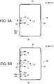
FIG. 5A is a plan view of the tray shown inFIG. 4 ; -
FIG. 5B is a modified example of the tray shown inFIG. 5A ; -
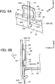
FIG. 6A is an enlarged perspective view of another mode of the main portion of the battery mounting structure according to the example embodiment; and -
FIG. 6B is a sectional view of the main portion shown inFIG. 6A . - Next, the battery mounting structure according to an example embodiment of the invention will be described with reference to
FIGS. 1 to 4 . In the drawings, arrow FR indicates a direction toward the front of the vehicle, and arrow UP indicates an upward direction with respect to the vehicle. Hereinafter, the terms front and rear will refer to the front and rear, respectively, in the vehicle longitudinal direction, and the terms up or upper and down or lower will refer to the upper and lower directions, respectively, in the vehicle vertical direction. -
FIG. 1 is a perspective view, as viewed diagonally from the front and above at an angle, of atray 38 and abattery 10 and the like to which the battery mounting structure according to this example embodiment has been applied.FIG. 2 is a sectional view taken along line II - II inFIG. 1 , andFIG. 3 is an enlarged sectional view of portion A shown inFIG. 2 . - As shown in
FIGS. 1 and2 , thebattery 10 is formed in a generally rectangular parallelepiped shape, and is retained by abattery bracket 12 that is made of sheet metal. Thebattery bracket 12 forms amount 14. The sectional shape of thismount 14 is a rectangular wavy shape that is open downward. Thebattery 10 is mounted onto this mount 14 (this will be described later). Here, thebattery 10 is not necessarily arranged such that aside wall 11 thereof extends in a vehicle width direction or a vehicle longitudinal direction, but for the sake of simplifying the description, it will be described as being arranged with theside wall 11 thereof extending in the vehicle longitudinal direction. - An attaching
piece 16 is provided on a front end portion of themount 14, and an attachingpiece 18 is provided on a rear end portion of themount 14. Aclamp 20 is fixed to this attachingpiece 18 in a position corresponding to a center portion, in the vehicle width direction, of thebattery 10 that is mounted onto themount 14. Theclamp 20 is made of generally rectangular-shaped sheet metal and is fixed to the attachingpiece 18 by welding or the like. Also, theclamp 20 is arranged extending in the vehicle height direction of thebattery 10, and an end portion (a lower end portion) of arear rod 22 is fixed to an upper end portion of theclamp 20 by welding or the like. - Also, a
hole 16A is provided in the attachingpiece 16 in a position corresponding to a center portion, in the vehicle width direction, of thebattery 10 that is mounted onto themount 14. As shown inFIG. 3 , ahook portion 24A that is provided on one end portion (a lower end portion) of a J-bolt 24 (rod) is inserted into thishole 16A. With thishook portion 24A inserted into thehole 16A, thehook portion 24A catches on an inside edge portion of thehole 16A and is thus retained. - Meanwhile, a fixing
plate 26 that is formed in a rectangular shape is arranged extending in the vehicle longitudinal direction, on an upper surface of thebattery 10. Amovement restricting piece 28 that has a generally L-shaped cross-section is provided on both end sides of the fixingplate 26 in the longitudinal direction. Thesemovement restricting pieces 28 restrict movement of a predetermined value or more of thebattery 10 in the vehicle longitudinal direction. - A through-
hole 26A is formed in a rear end portion of the fixingplate 26. The other end portion of therear rod 22 that is fixed to the upper end portion of theclamp 20 is inserted into this through-hole 26A. With the other end portion (i.e., the upper end portion) of therear rod 22 inserted into this through-hole 26A, anut 30 is fastened onto the other end portion of therear rod 22. - Also, a through-
hole 26B is formed in a front end portion of the fixingplate 26. The other end (i.e., the upper end portion) of the J-bolt 24 is able to be inserted into this through-hole 26B. After thenut 30 is fastened onto the other end portion of therear rod 22, the other end portion of the J-bolt 24 is inserted into the through-hole 26B and anut 32 is then fastened onto the other end portion of the J-bolt 24. - In this way, with the nuts 30 and 32 fastened, the
battery 10 is held to themount 14 in a state sandwiched between the fixingplate 26 and the mount 14 (i.e., the battery bracket 12) via the J-bolt 24 and therear rod 22. - Meanwhile, a fixing
piece 34 that has a generally L-shaped cross-section is fixed to the front side of themount 14 by welding or the like. Afastening portion 36 is provided on this fixingpiece 34, and a bolt, not shown, is able to be fastened by thisfastening portion 36. Thebattery bracket 12 is fixed to a body side, not shown, via this bolt. - Here, the
tray 38 made of resin is attached to themount 14, and thebattery 10 is mounted on thistray 38.FIG. 4 is a perspective view of thetray 38 viewed diagonally from the front and above at an angle. As shown inFIG. 4 , thetray 38 has a generally rectangular shape, and aflange portion 39 that stands erect rising upward is formed on a peripheral edge portion of thetray 38. Thisflange portion 39 is provided extending along in the vehicle width direction and in the vehicle longitudinal direction. - Also, as shown in
FIG. 2 , an outer dimension of aside wall 11 of thebattery 10 is set to be slightly smaller than an inner dimension betweenflange portions 39 that are arranged opposite one another. Therefore, when thebattery 10 is mounted on thetray 38, there is a gap between afront wall 11A of thebattery 10 and theflange portion 39 of thetray 38. -
FIG. 5 is a plan view of thetray 38. As shown inFIG. 5 , ribs (contact portions) 40 that serve as an interference inhibiting portion extend toward the rear from an inside wall of the center portion, in the vehicle width direction, of aflange portion 39A arranged on the front side. Theseribs 40 have generally rectangular shapes and are provided in plurality (five in this case) in the vehicle width direction (forming a rib group 41). Therib 40 positioned in the center of thisrib group 41 is arranged on a straight line P that connects the location of the center of gravity O of thebattery 10 with the J-bolt 24. Theribs 40 are formed parallel to one another. - Also, as shown in
FIG. 2 , the extension length of theribs 40 is set such that a gap is provided between tip end surfaces 40A of theribs 40 and thefront wall 11 A of thebattery 10. Further, the height of theribs 40 is set to approximately two times the height of theflange portion 39A in this case. Also, as shown inFIG. 4 , inclinedwalls 42 are provided at base portions (i.e., portions of theflange portion 39A) of theribs 40 that are arranged on the outside in the vehicle width direction, from among the plurality ofribs 40 that are provided. Upper end surfaces of the base portions of theribs 40 are connected to an upper end surface of theflange portion 39A by theinclined walls 42. - Next, the operation and effect of the battery mounting structure according to this example embodiment will be described.
- In this example embodiment, as shown in
FIG 2 , a gap H is provided between the J-bolt 24 and thefront wall 11A of thebattery 10 while thebattery 10 is fixed sandwiched between the fixingplate 26 and themount 14. Meanwhile, the plurality of ribs 40 (i.e., the rib group 41) extend toward the rear from the inside wall of the center portion, in the vehicle width direction, of theflange portion 39A arranged on the front side of thetray 38. - That is, the
ribs 40 and theflange portion 39A of thetray 38 are arranged between the J-bolt 24 and thefront wall 11 A of thebattery 10. When inertia force is applied toward the front of the vehicle (i.e., in the direction of arrow A; hereinafter this inertia force will simply be referred to as "forward inertia force") to thebattery 10 as a result of a frontal collision of the vehicle or the like, thefront wall 11 A of thebattery 10 comes into surface contact with the tip end surfaces 40A of the plurality ofribs 40. - If the
ribs 40 were not provided on thetray 38, for example, only theflange portion 39A of thetray 38 would be arranged between the J-bolt 24 and thefront wall 11A of the battery 10 (this case is not shown). Therefore, when forward inertia force is applied (i.e., in the direction of arrow A) to thebattery 10 as a result of a frontal collision of the vehicle or the like, thefront wall 11A of thebattery 10 comes into surface contact with theflange portion 39A of thetray 38. At this time, if theflange portion 39A were inclined toward the front side, then thebattery 10 would ride over thetray 38 along the inclined surface of theinclined flange portion 39A, and thefront wall 11A of thebattery 10 may end up interfering (i.e., colliding) with the J-bolt 24. - However, in this example embodiment, the plurality of
ribs 40 are provided on the inside wall of theflange portion 39A that is arranged on the front side of thetray 38, so the strength of thetray 38 itself is able to be increased. As a result, deformation of the tray is inhibited, so theflange portion 39A is able to be prevented from slanting. That is, when forward inertia force acts on thebattery 10, thebattery 10 moves forward (i.e., in the direction of arrow A). However, theribs 40 extend toward the rear from the inside wall of theflange portion 39A, so thefront wall 11 A of thebattery 10 comes into surface contact with the tip end surfaces 40A of the plurality ofribs 40. - In this way, interference between the
battery 10 and the J-bolt 24 is inhibited by thefront wall 11 A of thebattery 10 coming into surface contact with theribs 40. Therefore, damage to thebattery 10 due to interference with the J-bolt 24 is able to be inhibited. Also, because thefront wall 11 A of thebattery 10 comes into surface contact with the tip end surfaces 40A of theribs 40, the contact area between theribs 40 and thefront wall 11A of'the battery 10 is able to be larger than it is when thefront wall 11A of thebattery 10 comes into line contact with theribs 40. As a result, the surface pressure at the contact surfaces of theribs 40 and thefront wall 11 A of thebattery 10 can be decreased, so the load received by thebattery 10 can be reduced. - Here, a case in which the
front wall 11A of thebattery 10 comes into surface contact with theribs 40 is described. However, interference between thebattery 10 and the J-bolt 24 need only be inhibited, so thefront wall 11 A of thebattery 10 need only be able to come into contact with theribs 40. Therefore, a structure in which thefront wall 11 A of thebattery 10 comes into line contact with theribs 40 may also be employed. Also, thefront wall 11 A of thebattery 10 may also come into line contact with a patch 46 (seeFIG. 6 ) or the like that will be described later as a modified example of theribs 40, just as it does with theribs 40. - Also, in this example embodiment, the structure is not one that moves the J-
bolt 24 in order to inhibit interference between thebattery 10 and the J-bolt 24, so the arrangement of thebattery 10 is not restricted, e.g., it is not necessary to ensure space to move the J-bolt 24. - That is, according to the structure described above, interference between the
battery 10 and the J-bolt 24 due to inertia of thebattery 10 is able to be inhibited without the arrangement of thebattery 10 being restricted by restrictions such as those described above. The term "inhibit" in this case is intended to also include a case in which there is no interference between thefront wall 11A of thebattery 10 and the J-bolt 24. - Also, as shown in
FIG. 1 , the peripheral edge portion of thetray 38 is surrounded by theflange portions 39, so even if thebattery 10 were to leak battery fluid, the leaked battery fluid would be able to be collected by thetray 38. - Also in this example embodiment, as shown in
FIG 2 , theribs 40 that serve as the interference inhibiting portion are formed on the inside wall surface of theflange portion 39A that is positioned on the front side of thetray 38. Accordingly, when forward inertia force acts on thebattery 10 as a result of a frontal collision of the vehicle, thefront wall 11A of thebattery 10 comes into surface contact with the tip end surfaces 40A of theribs 40, and theribs 40 deform (i.e., elastically deform and plastic deform). The impact energy from the frontal collision of the vehicle is able to be absorbed by this deformation of theribs 40. The amount of impact energy that is absorbed can be adjusted according to the height and width and the like of theribs 40. In this example embodiment, the height of theribs 40 is approximately two times the height of theflange portion 39A, but the height of theribs 40 may also be equal to the height of theflange portion 39A or higher than the height of theflange portion 39A. - Meanwhile, as shown in
FIG. 5A , therib 40 that is positioned in the center of therib group 41 is arranged on the straight line P that connects the location of the center of gravity O of thebattery 10 with the J-bolt 24, and theribs 40 are formed parallel to one another. That is, theseribs 40 are arranged in the direction in which thebattery 10 will move, so impact energy from a frontal collision of the vehicle is able to be efficiently absorbed. - In this way, interference between the
battery 10 and the J-bolt 24 is able to be inhibited by forming theribs 40 on thetray 38, and thus is able to be realized by a simpler structure than one in which the contact portion that thefront wall 11A of thebattery 10 comes into surface contact with is formed separate from thetray 38 and then joined to thetray 38 by welding or adhesion or the like. - Also, in this example embodiment, the
ribs 40 extend toward thefront wall 11 A side of thebattery 10 from the inside wall surface of theflange portion 39A of thetray 38. Therefore, theribs 40 will not become undercut portions during mold release in a mold that forms thetray 38, so theribs 40 and thetray 38 are able to be integrally formed. - Typically, the J-
bolt 24 is made of metal. For example, a hole, not shown, is provided in theresin tray 38, and thehook portion 24A that is positioned on one end portion of the J-bolt 24 is hooked into this hole. In this case, when fastening the other end portion of the J-bolt 24 to the fixingplate 26, the hole may be damaged by axial force acting on the J-bolt 24. However, in this example embodiment, thehole 16A is provided in the attachingpiece 16 that is provided on thebattery bracket 12 made of sheet metal, and thehook portion 24A of the J-bolt 24 is retained in thishole 16A. Therefore, this kind of problem is inhibited. - Also, by using the J-
bolt 24 as a rod, thehook portion 24A of the J-bolt 24 is simply hooked into thehole 16A when attaching thebattery 10, so assemblability is better than it is when fastening one end portion of the rod to the battery bracket in a narrow space, which is not shown. A rod other than the J-bolt 24 may of course also be used. - In this example embodiment, as shown in
FIG. 5A , the plurality of ribs 40 (i.e., the rib group 41) are provided in the center portion, in the vehicle width direction, of theflange portion 39A that is positioned on the front side of thetray 38. In other words, theribs 40 are provided in positions opposite to the J-bolt 24. However, thisrib group 41 is not limited to being in the center portion of theflange portion 39A in the vehicle width direction. - For example, as shown in
FIG. 5B ,rib groups 45, each of which is formed by a plurality ofribs 44, may also be arranged one on each side, in the vehicle width direction, of therib group 41 that is arranged in the center portions, in the vehicle width direction, of theflange portion 39A, in a manner sandwiching the straight line P. In this case, a plurality ofribs 44 are provided, but of course it is also possible to provide only one. Further, therib groups 45 may be provided on both sides, in the vehicle width direction, of theflange portion 39, and therib group 41 may be omitted. - In this way, by providing the ribs 44 (i.e., the rib groups 45) other than the ribs 40 (i.e., the rib group 41) that are arranged in positions opposite to the J-
bolt 24, thefront wall 11 A of thebattery 10 is able to come into surface contact with theribs 40 and theribs 44. Therefore, impact energy from a frontal collision of the vehicle is able to be absorbed by theribs 44 as well. In this case, the extension length of theribs 44 may be set longer than that of theribs 40 so that impact energy is absorbed by therib groups 45 before it is absorbed by therib group 41. - In the example embodiment described above, a case is described in which the
front wall 11A of thebattery 10 is arranged extending in the vehicle width direction. However, thefront wall 11 A of thebattery 10 may also be arranged at an angle with respect to the vehicle width direction or the vehicle longitudinal direction. In this case, when forward inertia force acts on thebattery 10 as a result of a frontal collision of the vehicle, thefront wall 11 A of thebattery 10 tries to come into surface contact with theflange portion 39A of thetray 38 while at an angle to theflange portion 39A. - Therefore, as shown in
FIG. 5B , therib groups 45 may be provided one on each side of therib group 41 in the vehicle width direction, sandwiching the straight line. With this structure, thefront wall 11A of thebattery 10 will at least abut against theribs 44 that form therib groups 45, even when the front wall 1A of thebattery 10 comes in surface contact with theflange portion 39A of thetray 38 while at an angle to theflange portion 39A. As a result, impact energy is able to be absorbed. - Also, as shown in
FIG. 5A , a plurality of theribs 40 are provided in the vehicle width direction and extending from the inside wall of theflange portion 39A of thetray 38, but because thefront wall 11A of thebattery 10 only needs to come into surface contact, the shape of the ribs is not limited to this. For example, although not shown, a connecting rib that connects the tip end portions of theribs 40 together is provided and this connecting rib is formed parallel to theflange portion 39A. Accordingly, the contact area with thefront wall 11 A of thebattery 10 can be increased, so the surface pressure at the contact surfaces of the connecting rib and thefront wall 11 A of thebattery 10 can be decreased, so the load received by thebattery 10 can be reduced. - Also, aside from this, although not shown, a connecting rib that connects the tip end portions of the
ribs 40 that extend in the vehicle longitudinal direction may be provided, and a slanted rib that connects the base portion of onerib 40 to the tip end portion of anotherrib 40 that is adjacent to thatrib 40 may be provided. This slanted rib may be formed between theadjacent ribs 40, so as to form a triangular shape in which the rear side is the apex portion. - Also in this example embodiment, the
inclined walls 42 are provided on the base portions of theribs 40 that are arranged on the outside, and the upper end surface on the base portion side of theribs 40 is connected to the upper end surface of theflange portion 39A by theseinclined walls 42. However, theseinclined walls 42 do not necessarily have to be provided. - In the example embodiment described above, interference between the
battery 10 and the J-bolt 24 is inhibited by providing the plurality ofribs 40 on the inside wall of theflange portion 39A that is positioned on the front side of thetray 38, as shown inFIG. 2 . However, the structure is not limited to this as long as interference between thebattery 10 and the J-bolt 24 is able to be inhibited. - For example, as shown in
FIGS. 6A and 6B , apatch 46 that functions as a contact piece with which thefront wall 11 A of thebattery 10 is able to come into surface contact may be welded to the J-bolt 24. Thispatch 46 has a rectangular shape, and abent piece 48 that is bent toward the front side (i.e., the J-bolt 24 side) is provided on each of both end portions of thepatch 46 in the vehicle width direction. Thesebent pieces 48 increase the rigidity and strength of thepatch 46. - An
abutting surface portion 50 is provided on the center portion of thepatch 46. Thefront wall 11A of thebattery 10 is able to come into surface contact with this abuttingsurface portion 50 when forward inertia force acts on thebattery 10 as a result of a frontal collision of the vehicle. That is, interference between thebattery 10 and the J-bolt 24 is inhibited by thefront wall 11A of thebattery 10 coming into surface contact with this abuttingsurface portion 50. - Further, an
inclined piece 52 that forms a portion of a mounting leg portion and that is inclined in a direction in which it comes closer to the J-bolt 24 farther up or farther down, is provided on each of both end portions of theabutting surface portion 50 in the vehicle vertical direction. Awelding piece 54 that forms a portion of the mounting leg portion and that is bent upward or downward is formed on an end portion of thisinclined piece 52. Thiswelding piece 54 abuts against the J-bolt 24. An arc-shapedwelding portion 54A that has a curvature radius substantially the same as the outer diameter dimension of the J-bolt 24 is provided on the center portion of thewelding piece 54 in the vehicle width direction. Thiswelding portion 54A is welded to an outer peripheral surface of the J-bolt 24. In this way, the area of theabutting surface portion 50 is ensured by keeping the welding locations as few as possible. In this example embodiment, thepatch 46 is simply welded to the J-bolt 24, so a conventional part can be used as it is for the J-bolt 24. - Also, here, the
inclined piece 52 is provided on thepatch 46 and a gap is provided between theabutting surface portion 50 and the J-bolt 24. Therefore, if inertia force in a horizontal direction (i.e., the direction of arrow A) acts on thebattery 10 as a result of a frontal collision of the vehicle, and theabutting surface portion 50 is consequently pushed on by thefront wall 11A of thebattery 10, theinclined piece 52 will deform (i.e., elastically deform and plastic deform). As a result, impact energy from the frontal collision of the vehicle can be absorbed. In this way, a stroke for absorbing the impact load can be ensured by providing the gap between theabutting surface portion 50 and the J-bolt 24. - Here, the
inclined piece 52 is provided as a member that forms a portion of the mounting leg portion. However, it is sufficient to just have the gap be provided between theabutting surface portion 50 and the J-bolt 24, so the piece does not necessarily have to be an inclined piece. For example, the member that forms a portion of the mounting leg portion may also be a leg piece that is arranged orthogonal to theabutting surface portion 50 and the J-bolt 24. - While the invention has been described with reference to example embodiments thereof, it should be understood that the invention is not limited to the example embodiments. The invention may of course be carried out in other modes that have been modified or improved in any of a variety of ways without departing from the scope thereof.
Claims (8)
- A battery mounting structure comprising:a battery bracket (12) that is fixed to a body of a vehicle, and on which a battery (10) is mounted;a rod that is connected to the battery bracket in a state in which a gap is provided between the rod and a front wall (11 A) of the battery, and that fixes the battery to the battery bracket; and characterized byan interference inhibiting portion that is provided between the rod and the front wall of the battery, and that inhibits interference between the battery and the rod by the front wall of the battery contacting the interference inhibiting portion when forward inertia force toward a front of the vehicle acts on the battery,wherein the interference inhibiting portion is a contact portion formed on a tray that forms a portion of the battery mounting structure,wherein the contact portion extends toward the front wall of the battery,wherein the battery is mounted on the tray, andwherein the front wall of the battery is able to come into contact with the contact portion.
- The battery mounting structure according to claim 1,
wherein the tray is made of resin,
wherein a flange portion (39) stands erect on a peripheral edge portion of the tray that is plate-shaped,
wherein the contact portion is a plurality of ribs (40) that extend toward the front wall of the battery from an inside wall surface of the flange portion, and
wherein the plurality of the ribs are provided at intervals in a width direction of the battery. - The battery mounting structure according to claim 2, wherein the ribs are provided in positions opposite to the rod.
- The battery mounting structure according to claim 2 or 3, wherein the ribs are provided on both sides so as to sandwich a position opposite to the rod.
- The battery mounting structure according to any one of claims 2 to 4, wherein a height of the ribs is higher than a height of the flange portion.
- The battery mounting structure according to claim 2, wherein the rod is a J-shaped bolt (24), and one end portion of the J-shaped bolt is retained in a hole (16A) formed in the battery bracket that is made of metal.
- A battery mounting structure comprising:a battery bracket (12) that is fixed to a body of a vehicle, and on which a battery (10) is mounted;a rod that is connected to the battery bracket in a state in which a gap is provided between the rod and a front wall (11 A) of the battery, and that fixes the battery to the battery bracket; and characterized by an interference inhibiting portion that is provided between the rod and the front wall of the battery, and that inhibits interference between the battery and the rod by the front wall of the battery contacting the interference inhibiting portion when forward inertia force toward a front of the vehicle acts on the battery,wherein the interference inhibiting portion is a contact piece (46) that is welded to the rod, andwherein the front wall of the battery is able to come into contact with the contact piece.
- The battery mounting structure according to claim 7,
wherein the contact piece includes an abutting surface portion (50) that the front wall of the battery is able to come into contact with, and a pair of mounting leg portions that support the abutting surface portion, and end portions of which are welded to the rod,
and wherein a gap is provided between the abutting surface portion and the rod.
Applications Claiming Priority (2)
| Application Number | Priority Date | Filing Date | Title |
|---|---|---|---|
| JP2011206502A JP5772440B2 (en) | 2011-09-21 | 2011-09-21 | Battery mounting structure |
| PCT/IB2012/001832 WO2013041945A1 (en) | 2011-09-21 | 2012-09-20 | Battery mounting structure |
Publications (2)
| Publication Number | Publication Date |
|---|---|
| EP2759004A1 EP2759004A1 (en) | 2014-07-30 |
| EP2759004B1 true EP2759004B1 (en) | 2017-01-04 |
Family
ID=47040761
Family Applications (1)
| Application Number | Title | Priority Date | Filing Date |
|---|---|---|---|
| EP12773373.1A Active EP2759004B1 (en) | 2011-09-21 | 2012-09-20 | Battery mounting structure |
Country Status (4)
| Country | Link |
|---|---|
| EP (1) | EP2759004B1 (en) |
| JP (1) | JP5772440B2 (en) |
| CN (1) | CN103814458B (en) |
| WO (1) | WO2013041945A1 (en) |
Families Citing this family (7)
| Publication number | Priority date | Publication date | Assignee | Title |
|---|---|---|---|---|
| TWI655134B (en) * | 2015-03-06 | 2019-04-01 | 日商島野股份有限公司 | Electric bicycle rear derailleur |
| JP2017013557A (en) | 2015-06-29 | 2017-01-19 | スズキ株式会社 | Battery tray structure |
| JP6327241B2 (en) * | 2015-12-22 | 2018-05-23 | トヨタ自動車株式会社 | Battery carrier |
| JP6726428B2 (en) * | 2017-04-13 | 2020-07-22 | トヨタ車体株式会社 | Battery tray |
| JP7035802B2 (en) * | 2018-05-23 | 2022-03-15 | トヨタ自動車株式会社 | Battery retention structure |
| JP6670888B2 (en) * | 2018-05-31 | 2020-03-25 | 本田技研工業株式会社 | Battery fixing structure |
| CN115139956B (en) * | 2021-03-30 | 2026-02-27 | 本田技研工业株式会社 | Battery mounting structure |
Family Cites Families (19)
| Publication number | Priority date | Publication date | Assignee | Title |
|---|---|---|---|---|
| US3254736A (en) * | 1963-10-24 | 1966-06-07 | Perfect Parts Inc | Automotive battery securing device |
| JPS61180454U (en) * | 1985-04-30 | 1986-11-11 | ||
| US4684580A (en) * | 1986-01-21 | 1987-08-04 | Cramer Scott L | Electric storage battery assembly |
| JPS62133374U (en) * | 1986-02-18 | 1987-08-22 | ||
| JPH0537406Y2 (en) * | 1987-05-30 | 1993-09-21 | ||
| FI86926C (en) * | 1988-04-14 | 1992-10-26 | Neste Oy | FAUNTEKANISM FOER ACKUMULATOR |
| JPH0236162U (en) * | 1988-08-30 | 1990-03-08 | ||
| JPH02134653U (en) * | 1989-04-17 | 1990-11-08 | ||
| JPH035658U (en) * | 1989-06-06 | 1991-01-21 | ||
| JP2588841Y2 (en) * | 1992-07-16 | 1999-01-20 | 日野自動車工業株式会社 | Battery support structure |
| JPH0692191A (en) * | 1992-09-11 | 1994-04-05 | Nissan Motor Co Ltd | Battery fixing structure |
| JP3349349B2 (en) * | 1996-06-27 | 2002-11-25 | 三洋電機株式会社 | Battery mounting structure |
| JP2000255346A (en) * | 1999-03-05 | 2000-09-19 | Kojima Press Co Ltd | Battery holding device |
| JP4601837B2 (en) | 2001-02-06 | 2010-12-22 | 富士重工業株式会社 | Battery bracket structure |
| JP3736418B2 (en) * | 2001-10-12 | 2006-01-18 | 日産自動車株式会社 | Battery mounting structure |
| JP4039207B2 (en) | 2002-10-24 | 2008-01-30 | 三菱ふそうトラック・バス株式会社 | Electric vehicle battery device |
| JP4274819B2 (en) | 2003-03-04 | 2009-06-10 | 富士重工業株式会社 | Battery mounting structure |
| KR100836690B1 (en) * | 2006-08-22 | 2008-06-10 | 현대자동차주식회사 | Battery mounting structure to prevent twisting rotation of battery |
| CN201927649U (en) * | 2010-11-12 | 2011-08-10 | 奇瑞汽车股份有限公司 | Pallet board applied to electric automobile power storage battery |
-
2011
- 2011-09-21 JP JP2011206502A patent/JP5772440B2/en active Active
-
2012
- 2012-09-20 WO PCT/IB2012/001832 patent/WO2013041945A1/en not_active Ceased
- 2012-09-20 EP EP12773373.1A patent/EP2759004B1/en active Active
- 2012-09-20 CN CN201280045447.XA patent/CN103814458B/en active Active
Also Published As
| Publication number | Publication date |
|---|---|
| JP2013067251A (en) | 2013-04-18 |
| EP2759004A1 (en) | 2014-07-30 |
| CN103814458B (en) | 2017-05-17 |
| JP5772440B2 (en) | 2015-09-02 |
| WO2013041945A1 (en) | 2013-03-28 |
| CN103814458A (en) | 2014-05-21 |
Similar Documents
| Publication | Publication Date | Title |
|---|---|---|
| KR101428276B1 (en) | Battery tray for vehicle | |
| EP2759004A1 (en) | Battery mounting structure | |
| JP5125704B2 (en) | Side impact resin shock absorber | |
| US9545951B2 (en) | Structure for front part of vehicle | |
| KR101448747B1 (en) | Front vehicle body structure | |
| EP2647868B1 (en) | Shock absorbing member | |
| US9889886B2 (en) | Suspension member | |
| US7726709B2 (en) | Vehicle bumper structure | |
| JP5727883B2 (en) | Bumper structure for vehicles | |
| US20130038076A1 (en) | Vehicle bumper | |
| JP6927056B2 (en) | Body undercarriage | |
| US9738241B2 (en) | Bumper absorber attachment structure | |
| CN215266500U (en) | Battery package bottom protection plate and vehicle with same | |
| US20160222846A1 (en) | Sealing-equipped oil pan | |
| JP2022081455A (en) | How to install the battery protector, vehicle, and battery protector | |
| JP5553819B2 (en) | Vehicle fender panel support structure | |
| JP2014180933A (en) | Vehicle body floor and method of protecting batter unit mounted on vehicle body floor | |
| CN107010130A (en) | Spare tyre supporting structure | |
| KR20140044679A (en) | Front vehicle body structure | |
| JP2015121162A (en) | Vehicle component protection plate | |
| KR101450608B1 (en) | Hybrid bumper beam bracket install structure | |
| KR101664847B1 (en) | Hybrid crash box assembly satisfied vehicle impact characteristics | |
| CN204249968U (en) | Energy-absorption box mounting structure | |
| WO2013172137A1 (en) | Shock absorbing member | |
| CN219295537U (en) | Fender mounting bracket and vehicle |
Legal Events
| Date | Code | Title | Description |
|---|---|---|---|
| PUAI | Public reference made under article 153(3) epc to a published international application that has entered the european phase |
Free format text: ORIGINAL CODE: 0009012 |
|
| 17P | Request for examination filed |
Effective date: 20140317 |
|
| AK | Designated contracting states |
Kind code of ref document: A1 Designated state(s): AL AT BE BG CH CY CZ DE DK EE ES FI FR GB GR HR HU IE IS IT LI LT LU LV MC MK MT NL NO PL PT RO RS SE SI SK SM TR |
|
| DAX | Request for extension of the european patent (deleted) | ||
| GRAP | Despatch of communication of intention to grant a patent |
Free format text: ORIGINAL CODE: EPIDOSNIGR1 |
|
| RIC1 | Information provided on ipc code assigned before grant |
Ipc: H01M 2/10 20060101AFI20160620BHEP Ipc: B60R 16/04 20060101ALI20160620BHEP Ipc: H01M 2/34 20060101ALN20160620BHEP |
|
| INTG | Intention to grant announced |
Effective date: 20160704 |
|
| GRAS | Grant fee paid |
Free format text: ORIGINAL CODE: EPIDOSNIGR3 |
|
| STAA | Information on the status of an ep patent application or granted ep patent |
Free format text: STATUS: GRANT OF PATENT IS INTENDED |
|
| GRAA | (expected) grant |
Free format text: ORIGINAL CODE: 0009210 |
|
| STAA | Information on the status of an ep patent application or granted ep patent |
Free format text: STATUS: THE PATENT HAS BEEN GRANTED |
|
| RIN1 | Information on inventor provided before grant (corrected) |
Inventor name: HYODO, HIROKI Inventor name: SIMASAKI, OSAMU |
|
| AK | Designated contracting states |
Kind code of ref document: B1 Designated state(s): AL AT BE BG CH CY CZ DE DK EE ES FI FR GB GR HR HU IE IS IT LI LT LU LV MC MK MT NL NO PL PT RO RS SE SI SK SM TR |
|
| RAP1 | Party data changed (applicant data changed or rights of an application transferred) |
Owner name: TOYOTA JIDOSHA KABUSHIKI KAISHA |
|
| REG | Reference to a national code |
Ref country code: GB Ref legal event code: FG4D |
|
| RIN1 | Information on inventor provided before grant (corrected) |
Inventor name: HYODO, HIROKI Inventor name: SIMASAKI, OSAMU |
|
| REG | Reference to a national code |
Ref country code: CH Ref legal event code: EP |
|
| REG | Reference to a national code |
Ref country code: AT Ref legal event code: REF Ref document number: 860034 Country of ref document: AT Kind code of ref document: T Effective date: 20170115 |
|
| REG | Reference to a national code |
Ref country code: IE Ref legal event code: FG4D |
|
| REG | Reference to a national code |
Ref country code: DE Ref legal event code: R096 Ref document number: 602012027423 Country of ref document: DE |
|
| REG | Reference to a national code |
Ref country code: LT Ref legal event code: MG4D Ref country code: NL Ref legal event code: MP Effective date: 20170104 |
|
| REG | Reference to a national code |
Ref country code: AT Ref legal event code: MK05 Ref document number: 860034 Country of ref document: AT Kind code of ref document: T Effective date: 20170104 |
|
| REG | Reference to a national code |
Ref country code: DE Ref legal event code: R084 Ref document number: 602012027423 Country of ref document: DE |
|
| PG25 | Lapsed in a contracting state [announced via postgrant information from national office to epo] |
Ref country code: NL Free format text: LAPSE BECAUSE OF FAILURE TO SUBMIT A TRANSLATION OF THE DESCRIPTION OR TO PAY THE FEE WITHIN THE PRESCRIBED TIME-LIMIT Effective date: 20170104 |
|
| REG | Reference to a national code |
Ref country code: GB Ref legal event code: 746 Effective date: 20170621 |
|
| PG25 | Lapsed in a contracting state [announced via postgrant information from national office to epo] |
Ref country code: FI Free format text: LAPSE BECAUSE OF FAILURE TO SUBMIT A TRANSLATION OF THE DESCRIPTION OR TO PAY THE FEE WITHIN THE PRESCRIBED TIME-LIMIT Effective date: 20170104 Ref country code: NO Free format text: LAPSE BECAUSE OF FAILURE TO SUBMIT A TRANSLATION OF THE DESCRIPTION OR TO PAY THE FEE WITHIN THE PRESCRIBED TIME-LIMIT Effective date: 20170404 Ref country code: HR Free format text: LAPSE BECAUSE OF FAILURE TO SUBMIT A TRANSLATION OF THE DESCRIPTION OR TO PAY THE FEE WITHIN THE PRESCRIBED TIME-LIMIT Effective date: 20170104 Ref country code: LT Free format text: LAPSE BECAUSE OF FAILURE TO SUBMIT A TRANSLATION OF THE DESCRIPTION OR TO PAY THE FEE WITHIN THE PRESCRIBED TIME-LIMIT Effective date: 20170104 Ref country code: IS Free format text: LAPSE BECAUSE OF FAILURE TO SUBMIT A TRANSLATION OF THE DESCRIPTION OR TO PAY THE FEE WITHIN THE PRESCRIBED TIME-LIMIT Effective date: 20170504 Ref country code: GR Free format text: LAPSE BECAUSE OF FAILURE TO SUBMIT A TRANSLATION OF THE DESCRIPTION OR TO PAY THE FEE WITHIN THE PRESCRIBED TIME-LIMIT Effective date: 20170405 |
|
| REG | Reference to a national code |
Ref country code: FR Ref legal event code: PLFP Year of fee payment: 6 |
|
| PG25 | Lapsed in a contracting state [announced via postgrant information from national office to epo] |
Ref country code: BG Free format text: LAPSE BECAUSE OF FAILURE TO SUBMIT A TRANSLATION OF THE DESCRIPTION OR TO PAY THE FEE WITHIN THE PRESCRIBED TIME-LIMIT Effective date: 20170404 Ref country code: ES Free format text: LAPSE BECAUSE OF FAILURE TO SUBMIT A TRANSLATION OF THE DESCRIPTION OR TO PAY THE FEE WITHIN THE PRESCRIBED TIME-LIMIT Effective date: 20170104 Ref country code: SE Free format text: LAPSE BECAUSE OF FAILURE TO SUBMIT A TRANSLATION OF THE DESCRIPTION OR TO PAY THE FEE WITHIN THE PRESCRIBED TIME-LIMIT Effective date: 20170104 Ref country code: PL Free format text: LAPSE BECAUSE OF FAILURE TO SUBMIT A TRANSLATION OF THE DESCRIPTION OR TO PAY THE FEE WITHIN THE PRESCRIBED TIME-LIMIT Effective date: 20170104 Ref country code: RS Free format text: LAPSE BECAUSE OF FAILURE TO SUBMIT A TRANSLATION OF THE DESCRIPTION OR TO PAY THE FEE WITHIN THE PRESCRIBED TIME-LIMIT Effective date: 20170104 Ref country code: PT Free format text: LAPSE BECAUSE OF FAILURE TO SUBMIT A TRANSLATION OF THE DESCRIPTION OR TO PAY THE FEE WITHIN THE PRESCRIBED TIME-LIMIT Effective date: 20170504 Ref country code: AT Free format text: LAPSE BECAUSE OF FAILURE TO SUBMIT A TRANSLATION OF THE DESCRIPTION OR TO PAY THE FEE WITHIN THE PRESCRIBED TIME-LIMIT Effective date: 20170104 Ref country code: LV Free format text: LAPSE BECAUSE OF FAILURE TO SUBMIT A TRANSLATION OF THE DESCRIPTION OR TO PAY THE FEE WITHIN THE PRESCRIBED TIME-LIMIT Effective date: 20170104 |
|
| REG | Reference to a national code |
Ref country code: DE Ref legal event code: R097 Ref document number: 602012027423 Country of ref document: DE |
|
| PG25 | Lapsed in a contracting state [announced via postgrant information from national office to epo] |
Ref country code: SK Free format text: LAPSE BECAUSE OF FAILURE TO SUBMIT A TRANSLATION OF THE DESCRIPTION OR TO PAY THE FEE WITHIN THE PRESCRIBED TIME-LIMIT Effective date: 20170104 Ref country code: EE Free format text: LAPSE BECAUSE OF FAILURE TO SUBMIT A TRANSLATION OF THE DESCRIPTION OR TO PAY THE FEE WITHIN THE PRESCRIBED TIME-LIMIT Effective date: 20170104 Ref country code: IT Free format text: LAPSE BECAUSE OF FAILURE TO SUBMIT A TRANSLATION OF THE DESCRIPTION OR TO PAY THE FEE WITHIN THE PRESCRIBED TIME-LIMIT Effective date: 20170104 Ref country code: RO Free format text: LAPSE BECAUSE OF FAILURE TO SUBMIT A TRANSLATION OF THE DESCRIPTION OR TO PAY THE FEE WITHIN THE PRESCRIBED TIME-LIMIT Effective date: 20170104 Ref country code: CZ Free format text: LAPSE BECAUSE OF FAILURE TO SUBMIT A TRANSLATION OF THE DESCRIPTION OR TO PAY THE FEE WITHIN THE PRESCRIBED TIME-LIMIT Effective date: 20170104 |
|
| PLBE | No opposition filed within time limit |
Free format text: ORIGINAL CODE: 0009261 |
|
| STAA | Information on the status of an ep patent application or granted ep patent |
Free format text: STATUS: NO OPPOSITION FILED WITHIN TIME LIMIT |
|
| PG25 | Lapsed in a contracting state [announced via postgrant information from national office to epo] |
Ref country code: SM Free format text: LAPSE BECAUSE OF FAILURE TO SUBMIT A TRANSLATION OF THE DESCRIPTION OR TO PAY THE FEE WITHIN THE PRESCRIBED TIME-LIMIT Effective date: 20170104 Ref country code: DK Free format text: LAPSE BECAUSE OF FAILURE TO SUBMIT A TRANSLATION OF THE DESCRIPTION OR TO PAY THE FEE WITHIN THE PRESCRIBED TIME-LIMIT Effective date: 20170104 |
|
| 26N | No opposition filed |
Effective date: 20171005 |
|
| PG25 | Lapsed in a contracting state [announced via postgrant information from national office to epo] |
Ref country code: SI Free format text: LAPSE BECAUSE OF FAILURE TO SUBMIT A TRANSLATION OF THE DESCRIPTION OR TO PAY THE FEE WITHIN THE PRESCRIBED TIME-LIMIT Effective date: 20170104 |
|
| REG | Reference to a national code |
Ref country code: CH Ref legal event code: PL |
|
| PG25 | Lapsed in a contracting state [announced via postgrant information from national office to epo] |
Ref country code: MC Free format text: LAPSE BECAUSE OF FAILURE TO SUBMIT A TRANSLATION OF THE DESCRIPTION OR TO PAY THE FEE WITHIN THE PRESCRIBED TIME-LIMIT Effective date: 20170104 |
|
| REG | Reference to a national code |
Ref country code: IE Ref legal event code: MM4A |
|
| REG | Reference to a national code |
Ref country code: BE Ref legal event code: MM Effective date: 20170930 |
|
| PG25 | Lapsed in a contracting state [announced via postgrant information from national office to epo] |
Ref country code: LU Free format text: LAPSE BECAUSE OF NON-PAYMENT OF DUE FEES Effective date: 20170920 |
|
| PG25 | Lapsed in a contracting state [announced via postgrant information from national office to epo] |
Ref country code: IE Free format text: LAPSE BECAUSE OF NON-PAYMENT OF DUE FEES Effective date: 20170920 Ref country code: LI Free format text: LAPSE BECAUSE OF NON-PAYMENT OF DUE FEES Effective date: 20170930 Ref country code: CH Free format text: LAPSE BECAUSE OF NON-PAYMENT OF DUE FEES Effective date: 20170930 |
|
| REG | Reference to a national code |
Ref country code: FR Ref legal event code: PLFP Year of fee payment: 7 |
|
| PG25 | Lapsed in a contracting state [announced via postgrant information from national office to epo] |
Ref country code: BE Free format text: LAPSE BECAUSE OF NON-PAYMENT OF DUE FEES Effective date: 20170930 |
|
| PG25 | Lapsed in a contracting state [announced via postgrant information from national office to epo] |
Ref country code: MT Free format text: LAPSE BECAUSE OF NON-PAYMENT OF DUE FEES Effective date: 20170920 |
|
| PG25 | Lapsed in a contracting state [announced via postgrant information from national office to epo] |
Ref country code: HU Free format text: LAPSE BECAUSE OF FAILURE TO SUBMIT A TRANSLATION OF THE DESCRIPTION OR TO PAY THE FEE WITHIN THE PRESCRIBED TIME-LIMIT; INVALID AB INITIO Effective date: 20120920 |
|
| PG25 | Lapsed in a contracting state [announced via postgrant information from national office to epo] |
Ref country code: CY Free format text: LAPSE BECAUSE OF NON-PAYMENT OF DUE FEES Effective date: 20170104 |
|
| PG25 | Lapsed in a contracting state [announced via postgrant information from national office to epo] |
Ref country code: MK Free format text: LAPSE BECAUSE OF FAILURE TO SUBMIT A TRANSLATION OF THE DESCRIPTION OR TO PAY THE FEE WITHIN THE PRESCRIBED TIME-LIMIT Effective date: 20170104 |
|
| PG25 | Lapsed in a contracting state [announced via postgrant information from national office to epo] |
Ref country code: TR Free format text: LAPSE BECAUSE OF FAILURE TO SUBMIT A TRANSLATION OF THE DESCRIPTION OR TO PAY THE FEE WITHIN THE PRESCRIBED TIME-LIMIT Effective date: 20170104 |
|
| PG25 | Lapsed in a contracting state [announced via postgrant information from national office to epo] |
Ref country code: AL Free format text: LAPSE BECAUSE OF FAILURE TO SUBMIT A TRANSLATION OF THE DESCRIPTION OR TO PAY THE FEE WITHIN THE PRESCRIBED TIME-LIMIT Effective date: 20170104 |
|
| REG | Reference to a national code |
Ref country code: DE Ref legal event code: R079 Ref document number: 602012027423 Country of ref document: DE Free format text: PREVIOUS MAIN CLASS: H01M0002100000 Ipc: H01M0050200000 |
|
| P01 | Opt-out of the competence of the unified patent court (upc) registered |
Effective date: 20230427 |
|
| PGFP | Annual fee paid to national office [announced via postgrant information from national office to epo] |
Ref country code: DE Payment date: 20250730 Year of fee payment: 14 |
|
| PGFP | Annual fee paid to national office [announced via postgrant information from national office to epo] |
Ref country code: GB Payment date: 20250731 Year of fee payment: 14 |
|
| PGFP | Annual fee paid to national office [announced via postgrant information from national office to epo] |
Ref country code: FR Payment date: 20250808 Year of fee payment: 14 |