EP2758856B1 - Electrode configuration for position detection with capacitive touch sensor and method for position detection - Google Patents
Electrode configuration for position detection with capacitive touch sensor and method for position detection Download PDFInfo
- Publication number
- EP2758856B1 EP2758856B1 EP12774971.1A EP12774971A EP2758856B1 EP 2758856 B1 EP2758856 B1 EP 2758856B1 EP 12774971 A EP12774971 A EP 12774971A EP 2758856 B1 EP2758856 B1 EP 2758856B1
- Authority
- EP
- European Patent Office
- Prior art keywords
- electrode
- electrodes
- coupling capacity
- receiving
- configuration
- Prior art date
- Legal status (The legal status is an assumption and is not a legal conclusion. Google has not performed a legal analysis and makes no representation as to the accuracy of the status listed.)
- Not-in-force
Links
- 238000000034 method Methods 0.000 title claims description 13
- 238000001514 detection method Methods 0.000 title description 62
- 230000008878 coupling Effects 0.000 claims description 68
- 238000010168 coupling process Methods 0.000 claims description 68
- 238000005859 coupling reaction Methods 0.000 claims description 68
- 238000005259 measurement Methods 0.000 claims description 45
- 230000001154 acute effect Effects 0.000 claims description 26
- 230000008859 change Effects 0.000 claims description 19
- 238000011068 loading method Methods 0.000 claims description 6
- 210000003811 finger Anatomy 0.000 description 46
- 238000010521 absorption reaction Methods 0.000 description 10
- 238000013459 approach Methods 0.000 description 9
- 238000010586 diagram Methods 0.000 description 9
- 230000005540 biological transmission Effects 0.000 description 6
- 230000000694 effects Effects 0.000 description 6
- 239000003990 capacitor Substances 0.000 description 5
- 239000000463 material Substances 0.000 description 4
- 230000008901 benefit Effects 0.000 description 3
- 238000013461 design Methods 0.000 description 3
- 239000010410 layer Substances 0.000 description 3
- 230000004913 activation Effects 0.000 description 2
- 230000001143 conditioned effect Effects 0.000 description 2
- 239000004020 conductor Substances 0.000 description 2
- 238000005265 energy consumption Methods 0.000 description 2
- 238000011156 evaluation Methods 0.000 description 2
- 238000004519 manufacturing process Methods 0.000 description 2
- 239000002356 single layer Substances 0.000 description 2
- 230000003321 amplification Effects 0.000 description 1
- 230000007423 decrease Effects 0.000 description 1
- 230000001419 dependent effect Effects 0.000 description 1
- 230000036039 immunity Effects 0.000 description 1
- 230000002452 interceptive effect Effects 0.000 description 1
- 238000012986 modification Methods 0.000 description 1
- 230000004048 modification Effects 0.000 description 1
- 238000003199 nucleic acid amplification method Methods 0.000 description 1
- 238000012545 processing Methods 0.000 description 1
- 230000009467 reduction Effects 0.000 description 1
- 230000035945 sensitivity Effects 0.000 description 1
- 210000003813 thumb Anatomy 0.000 description 1
Images
Classifications
-
- G—PHYSICS
- G06—COMPUTING; CALCULATING OR COUNTING
- G06F—ELECTRIC DIGITAL DATA PROCESSING
- G06F3/00—Input arrangements for transferring data to be processed into a form capable of being handled by the computer; Output arrangements for transferring data from processing unit to output unit, e.g. interface arrangements
- G06F3/01—Input arrangements or combined input and output arrangements for interaction between user and computer
- G06F3/03—Arrangements for converting the position or the displacement of a member into a coded form
- G06F3/041—Digitisers, e.g. for touch screens or touch pads, characterised by the transducing means
- G06F3/044—Digitisers, e.g. for touch screens or touch pads, characterised by the transducing means by capacitive means
- G06F3/0445—Digitisers, e.g. for touch screens or touch pads, characterised by the transducing means by capacitive means using two or more layers of sensing electrodes, e.g. using two layers of electrodes separated by a dielectric layer
-
- G—PHYSICS
- G01—MEASURING; TESTING
- G01D—MEASURING NOT SPECIALLY ADAPTED FOR A SPECIFIC VARIABLE; ARRANGEMENTS FOR MEASURING TWO OR MORE VARIABLES NOT COVERED IN A SINGLE OTHER SUBCLASS; TARIFF METERING APPARATUS; MEASURING OR TESTING NOT OTHERWISE PROVIDED FOR
- G01D5/00—Mechanical means for transferring the output of a sensing member; Means for converting the output of a sensing member to another variable where the form or nature of the sensing member does not constrain the means for converting; Transducers not specially adapted for a specific variable
- G01D5/12—Mechanical means for transferring the output of a sensing member; Means for converting the output of a sensing member to another variable where the form or nature of the sensing member does not constrain the means for converting; Transducers not specially adapted for a specific variable using electric or magnetic means
- G01D5/14—Mechanical means for transferring the output of a sensing member; Means for converting the output of a sensing member to another variable where the form or nature of the sensing member does not constrain the means for converting; Transducers not specially adapted for a specific variable using electric or magnetic means influencing the magnitude of a current or voltage
- G01D5/24—Mechanical means for transferring the output of a sensing member; Means for converting the output of a sensing member to another variable where the form or nature of the sensing member does not constrain the means for converting; Transducers not specially adapted for a specific variable using electric or magnetic means influencing the magnitude of a current or voltage by varying capacitance
-
- G—PHYSICS
- G06—COMPUTING; CALCULATING OR COUNTING
- G06F—ELECTRIC DIGITAL DATA PROCESSING
- G06F3/00—Input arrangements for transferring data to be processed into a form capable of being handled by the computer; Output arrangements for transferring data from processing unit to output unit, e.g. interface arrangements
- G06F3/01—Input arrangements or combined input and output arrangements for interaction between user and computer
- G06F3/03—Arrangements for converting the position or the displacement of a member into a coded form
- G06F3/041—Digitisers, e.g. for touch screens or touch pads, characterised by the transducing means
- G06F3/044—Digitisers, e.g. for touch screens or touch pads, characterised by the transducing means by capacitive means
-
- H—ELECTRICITY
- H03—ELECTRONIC CIRCUITRY
- H03K—PULSE TECHNIQUE
- H03K17/00—Electronic switching or gating, i.e. not by contact-making and –breaking
- H03K17/94—Electronic switching or gating, i.e. not by contact-making and –breaking characterised by the way in which the control signals are generated
- H03K17/96—Touch switches
- H03K17/962—Capacitive touch switches
-
- H—ELECTRICITY
- H03—ELECTRONIC CIRCUITRY
- H03K—PULSE TECHNIQUE
- H03K2217/00—Indexing scheme related to electronic switching or gating, i.e. not by contact-making or -breaking covered by H03K17/00
- H03K2217/94—Indexing scheme related to electronic switching or gating, i.e. not by contact-making or -breaking covered by H03K17/00 characterised by the way in which the control signal is generated
- H03K2217/96—Touch switches
- H03K2217/96066—Thumbwheel, potentiometer, scrollbar or slider simulation by touch switch
Definitions
- the invention relates to an electrode configuration for a capacitive sensor system, in particular for detecting a position of an object relative to the electrode configuration, as well as a method for detecting a position of an object relative to the electrode configuration according to the invention.
- the approach of an object towards a sensor zone substantially is measured contactless by means of generation and measurement of electric alternating fields.
- Derived from the measurement signal may be functions, for example switching functions, of an electric device, in particular an electric handheld device.
- the capacitive sensor system may be used in different electronic devices it is further desired that the capacitive sensor system preferably is independent of the grounding state of the respective electronic device.
- Electrodes in particular for capacitive sensor systems, which function according to the so called loading method, wherein, for example for implementing a sliding controller (in a sliding controller it is important that the position of an object, for example of a finger, may be detected along the sliding controller) a plurality of sensor electrodes arranged side by side and adjacent to each other, respectively, is provided.
- a sliding controller in a sliding controller it is important that the position of an object, for example of a finger, may be detected along the sliding controller
- a plurality of sensor electrodes arranged side by side and adjacent to each other, respectively.
- US Patent Application Publication US 2009/0184920 discloses a two element slider with guard sensor.
- US Patent Application Publication US 2011/017523 discloses a single layer touch sensor.
- US Patent US 7,218,124 discloses capacitive sensing apparatus designs.
- US Patent US 5,136,286 discloses a switched capacitance meter reading device using variable width electrodes.
- US Patent Application Publication US2011/0062971 discloses single layer transcapacitive sensing.
- the sensor electrode is loaded with an electric alternating signal, so that an electric alternating field is emitted therefrom, wherein the capacitive load of the sensor electrode (for example by an approach of a finger towards the sensor electrode) is detected and evaluated, respectively, by means of an evaluation device.
- the capacitive load of the sensor electrode for example by an approach of a finger towards the sensor electrode
- the detected capacitive load it may be determined at which sensor electrode an approach of the finger has taken place.
- capacitive sensor systems which also have a large number of sensor electrodes, wherein it is required for an exact detection of the position that, for example, a finger covers several sensor electrodes at the same time when contacting the sensor electrodes. Again, because of the large number of sensor electrodes required for a high position resolution the constructive effort for the manufacturing process is increased significantly.
- an electrode configuration for a capacitive sensor system and a method for detecting a position of an object relative to an electrode configuration according to the independent patent claims.
- Advantageous embodiments and improvements of the invention are given in the respective dependent claims.
- An integral part of the solution also is an electric device, in particular an electric handheld device, which has at least one capacitive sensor system comprising at least one electrode configuration according to the invention.
- a method for detecting a position of an object relative to an electrode configuration comprising at least three electrodes, wherein a first electrode is arranged parallel or concentrically with respect to a second electrode, a third electrode is arranged in an acute angle or excentric relative to the first electrode, the first electrode is loaded with a first generator signal, and wherein
- the second generator signal is inverse with respect to the first generator signal.
- the variation of the first coupling capacity substantially is proportional to the exposure of the electrode arrangement by the object
- the variation of the second coupling capacity substantially is proportional to the product of coverage and position of the object relative to the electrode arrangement.
- the variation of the first coupling capacity and the variation of the second coupling capacity each are determined as a variation with respect to the respective coupling capacity in the basic state of the electrode configuration.
- an electrode configuration for a capacitive sensor system in particular for detecting a position of an object relative to the electrode arrangement
- the electrode configuration has a first position detection electrode arrangement that comprises a first electrode and a second electrode, wherein the first electrode is operable as a transmitting electrode and the second electrode is operable as a receiving electrode, wherein the first electrode is arranged in an acute angle relative to the second electrode, and wherein the first electrode may be loaded with a first generator signal.
- the electrode configuration further may have at least one coverage detection electrode arrangement, which comprises a third electrode and a fourth electrode, wherein the third electrode may be operated as transmitting electrode and may be loaded with the first generator signal.
- the third electrode of the coverage detection electrode arrangement may be formed by the first electrode of the position detection electrode arrangement (common electrode of the coverage detection electrode arrangement and of the position detection electrode arrangement).
- the electrode configuration further may comprise a second position detection electrode arrangement, which comprises a fifth electrode and a sixth electrode, wherein the fifth electrode is arranged in an acute angle relative to the sixth electrode.
- the second electrode of the first position detection electrode arrangement may be arranged substantially parallel with respect to the fifth electrode of the second position detection electrode arrangement.
- the sixth electrode of the second position detection electrode arrangement is formed by the second electrode of the first position detection electrode arrangement (common electrode of the first position detection electrode arrangement and of the second position detection electrode arrangement), wherein the fifth electrode may be operated as transmitting electrode and may be loaded with the first generator signal.
- the second electrode of the first position detection electrode arrangement substantially may be arranged concentrically with respect to the fifth electrode of the second position detection electrode arrangement.
- the third electrode substantially may be arranged parallel to the fourth electrode.
- the second electrode or the fourth electrode or the sixth electrode may be loaded with a second generator signal, wherein the electrodes not loaded with a generator signal are operable as receiving electrodes.
- the second generator signal is formed inverse with respect to the first generator signal.
- the electrode loaded with the first or second generator signal is coupled with at least one receiving electrode via a coupling capacity C Comp , wherein the coupling capacity is configured as a discrete capacitor or as a conductor path coupling.
- the electrode configuration comprises three electrodes, wherein a first electrode and a second electrode substantially are arranged parallel to one another, and wherein a third electrode is arranged in an acute angle relative to the first electrode and/or the second electrode.
- the third electrode may be arranged between the first electrode and the second electrode, wherein the third electrode is arranged in an acute angle relative to the first electrode and the second electrode.
- first electrode and the second electrode are operable as transmitting electrodes and the third electrode is operable as receiving electrode, wherein the first electrode may be loaded with a first generator signal and the second electrode may be loaded with a second generator signal.
- the second electrode and the third electrode are operable as transmitting electrodes and the first electrode is operable as receiving electrode, wherein the second electrode may be loaded with the first generator signal and the third electrode may be loaded with the second generator signal.
- the first generator signal may be inverse with respect to the second generator signal.
- the electrode configuration comprises four electrodes, wherein a first electrode and a second electrode substantially are arranged parallel with respect to each other, wherein a third electrode is arranged in an acute angle relative to the first electrode and/or the second electrode, and wherein a fourth electrode is arranged in an acute angle relative to the third electrode.
- the second electrode and the fourth electrode are operable as transmitting electrodes and the first electrode is operable as receiving electrode, wherein the second electrode may be loaded with a first generator signal and the fourth electrode may be loaded with a second generator signal.
- the second electrode and the fourth electrode are operable as transmitting electrodes and the third electrode is operable as receiving electrode, wherein the second electrode may be loaded with the first generator signal and the fourth electrode may be loaded with the second generator signal.
- the first generator signal may be inverse with respect to the second generator signal.
- the electrode configuration comprises four electrodes, wherein a first electrode and a second electrode substantially are arranged parallel to one another, wherein a third electrode is arranged in an acute angle relative to the first electrode, and wherein a fourth electrode is arranged in an acute angle relative to the second electrode.
- the first electrode and a second electrode are arranged between the third electrode and the fourth electrode.
- the third electrode and the fourth electrode are operable as transmitting electrodes, and the first electrode and the second electrode are operable as receiving electrodes, wherein the third electrode may be loaded with a first generator signal and the fourth electrode may be loaded with a second generator signal.
- the first generator signal may be inverse with respect to the second generator signal.
- an electric device in particular an electric handheld device, which at least comprises a capacitive sensor system that comprises an electrode configuration according to the invention.
- the electric device and the electric handheld device may be a smart phone, a mobile radio unit, a computer mouse, a device remote control, a digital camera, a game controller, a mobile mini-computer, a tablet-PC, a dictating machine, a media player or the like.
- the sensor system according to the invention for detecting a position of an object relative to an electrode arrangement of the sensor system is configured as a capacitive sensor, which is operated in the operating mode "absorption".
- the sensor system according to the invention is configured such that the sensor signals of the sensor system provide two informations:
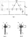
- Fig. 1 shows an equivalent circuit diagram of a capacitive sensor system for illustrating the absorption effect and for illustrating the measures by which the sensor system is made independent of the grounding state of the sensor system.
- the electrodes Tx (transmitting electrode) and Rx (receiving electrode) are arranged adjacent to each other, so that a basic capacitive coupling C 12 is formed between them.
- the basic capacitive coupling C 12 becomes smaller (absorption), so that the electric current flowing through C 12 becomes smaller as well.
- the capacitive coupling between the electrode Tx and the finger F is denoted by C 1H
- the capacitive coupling between Rx and the finger is denoted by C 2H .
- the coupling capacities C 1H and C 2H become larger. Produced from that and parallel to C 12 is a current path between the electrode Tx and the electrode Rx that may be interpreted as transmission.
- This current path parallel to C 12 has to be reduced, preferably has to be inhibited by means of suitable measures, as described in the following:
- two transmitting electrodes +Tx in Fig. 1 denoted by Tx
- -Tx in Fig. 1 denoted by Tx2
- the transmitting signals and the generator signals, respectively, which are applied to the electrodes +Tx and -Tx are inverse with respect to each other, i.e. the sum of the alternating portions of the electrode signals +Tx and -Tx equals zero.
- the receiving electrode Rx is designed such and arranged such relative to the transmitting electrodes +Tx, -Tx, respectively, that a capacitive coupling substantially only exists with one of the transmitting electrodes +Tx or -Tx.
- the transmission current by means of a respective sensor layout and by means of a respective isolating layer thickness is reduced such that also a sensor system only comprising one transmitting electrode +Tx may be constructed, which is largely independent of the grounding state.
- the sensor system When the grounding state (grounded or non-grounded) of the sensor system is known and largely constant, the sensor system also may be constructed comprising only one active transmitting electrode +Tx.
- the electrode configuration of a capacitive sensor system according to the invention for detecting a position of an object relative to the electrode configuration substantially comprises two electrode arrangements:
- Fig. 2a shows a coverage detection electrode arrangement according to the invention for detecting the coverage of the electrodes by an object, for example a finger.
- the coverage detection electrode arrangement comprises two electrodes Tx and Rx, wherein the electrodes Tx, Rx substantially are arranged parallel with respect to each other.
- the two electrodes Tx, Rx may have the same electrode width.
- the electrode length and electrode surface area covered by the finger F may be detected independent of the position of the finger F.
- the sensor signal substantially is proportional to the covered electrode length and electrode surface area, respectively.
- the electrodes Tx, Rx may be covered with a layer of isolating material.
- the coupling capacity between the transmitting electrode Tx and the receiving electrode Rx changes, wherein the variation of the coupling capacity is independent of the position in which the finger approaches the electrodes Tx, Rx and at which position the finger contacts the electrodes Tx, Rx, respectively.
- the detection of the coverage may also be provided for to switch the sensor device from a first operating mode into a second operating mode, for example from a sleeping mode into an active mode.
- a predetermined threshold value may be provided, which has to be exceeded before a change of the operating mode is carried out.
- the threshold value may include a minimum covering and/or a minimum duration of a coverage.
- Fig. 2b shows a position detection electrode arrangement according to the invention for detecting the position of an object relative to the electrodes.
- the position detection electrode arrangement comprises two electrodes Tx and Rx, wherein the electrodes Tx, Rx substantially are arranged in an acute angle ⁇ relative to one another.
- the two electrodes Tx, Rx may have the same electrode width.
- the position P of the finger F relative to the electrodes may be detected depending on the electrode length and electrode surface area, respectively, covered by the finger F.
- the sensor signal substantially is proportional to the covered electrode length and electrode surface area, respectively, as well as substantially proportional to the position P of the finger F.
- the electrodes Tx, Rx may be covered with a layer of isolating material.
- the coupling capacity between the transmitting electrode Tx and the receiving electrode Rx at the respective position changes.
- the result of the calculation itself here is independent of the coverage. This means that the position is detected and determined, respectively, in a correct manner independent of the width of the fingers covering the electrodes (finger of a child or finger of an adult), independent of the variation of the width of the covering (for example when the width of an object is changing while the object is moved relative to the electrodes), independent of the distance or a change in distance of the fingers covering the electrodes, and in particular independent of whether a glove is used.
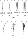
- Fig. 3 (a) to Fig. 3 (d) show electrode configurations according to the invention, which each comprise at least one position detection electrode arrangement.
- Fig. 3 (a) shows an electrode configuration according to the invention, which is composed of a coverage detection electrode arrangement and a position detection electrode arrangement.
- the coverage detection electrode arrangement the coverage (length and surface area, respectively, of the coverage) is detected.
- the position detection electrode arrangement the position of a finger F is detected relative to the electrode configuration.
- the coverage detection electrode arrangement is formed by the electrodes E1 and E2.
- the position detection electrode arrangement is formed by the electrodes E2 and E3. Therefore, the electrode E2 constitutes a common electrode for the coverage detection electrode arrangement and the position detection electrode arrangement.
- the electrode E1 is operated as receiving electrode Rx and the electrodes E2 and E3 each are operated as transmitting electrodes Tx, wherein the electrode E3 is loaded with a generator signal, which is inverse with respect to the generator signal, which is applied to electrode E2.
- the position of the finger F relative to the electrode configuration is detected, wherein in calculating the position the coverage is accounted for (see formula 2 above).
- the electrodes E1 and E2 each are operated as a transmitting electrode and the electrode E3 is operated as receiving electrode.
- the electrode E1 is loaded with a generator signal, which is inverse with respect to the generator signal, which is applied to electrode E2. It may be provided for that the position only then is detected and determined, respectively, when the coverage exceeds a predetermined threshold value. In doing so, the energy consumption may be lowered significantly, which in particular is advantageous in devices and handheld devices, respectively, operated by means of a battery or a rechargeable battery.
- Fig. 3 (b) shows an electrode configuration according to the invention, which is composed of two position detection electrode arrangements.
- the first position detection electrode arrangement is formed by electrodes E1 and E2, wherein the electrode E1 is arranged in an acute angle with respect to electrode E2.
- the second position detection electrode arrangement is formed by the electrodes E2 and E3, wherein the electrode E3 is arranged in an acute angle with respect to electrode E2. Therefore, electrode E2 forms a common electrode for the two position detection electrode arrangements.
- the electrode E1 is operated as receiving electrode and the electrodes E2 and E3 are operated as transmitting electrodes.
- the generator signal applied to electrode E2 is inverse with respect to the generator signal applied to electrode E3.
- a first position POS1 is measured.
- the electrode E3 is operated as receiving electrode and the electrodes E2 and E1 are operated as transmitting electrodes.
- the generator signal applied to electrode E2 is inverse with respect to the generator signal applied to electrode E1.
- a second position POS2 is measured.
- Fig. 3 (e) shows an electrode configuration according to the invention, which is composed of two position detection electrode arrangements and one coverage detection electrode arrangement.
- the first position detection electrode arrangement is formed by electrode E1 and E2, wherein electrode E1 is arranged in an acute angle with respect to electrode E2.
- the second position detection electrode arrangement is formed by electrodes E2 and E3, wherein electrode E3 is arranged in an acute angle with respect to electrode E2. Therefore, electrode E2 forms a common electrode for the two position detection electrode arrangements.
- the coverage detection electrode arrangement is formed by electrodes E3 and E4, wherein electrode E3 substantially is arranged parallel to electrode E4. Therefore, electrode E3 forms a common electrode for the second position detection electrode arrangement and the coverage detection electrode arrangement.
- electrode E4 is operated as receiving electrode Rx and electrodes E1 and E3 each are operated as transmitting electrodes Tx, wherein electrode E3 is loaded with a generator signal, which is inverse with respect to the generator signal, which is applied to electrode E1. In doing so, the detection of the coverage substantially is carried out independent of the grounding conditions of the sensor system.
- the position of the finger F relative to the electrode configuration is detected, wherein during the calculation of the position the coverage is accounted for (see formula 2 above).
- the electrodes E1 and E3 each are operated as transmitting electrodes and the electrode E2 is operated as receiving electrode.
- the electrode E1 is loaded with a generator signal, which is inverse with respect to the generator signal, which is applied to electrode E3. It may be provided for that the position only then is detected and determined, respectively, when the coverage exceeds a predetermined threshold value. In doing so, the energy consumption may be reduced significantly, which in particular is advantageous in devices and handheld devices, respectively, operated by a battery or a rechargeable battery.
- the electrode configuration shown in Fig. 3 (c) has the advantage over the electrode configuration shown in Fig. 3 (a) that the transmitting electrodes E1 and E3 do not have to be switched in between the measurement of the coverage and the measurement of the position.
- a further advantage over the electrode configuration of Fig. 3 (a) is that the measurement signal (sensor signal) shows a larger amplitude during the measurement of the position and has a better linearity with respect to the position.
- Fig. 3 (d) shows an electrode configuration according to the invention, which is composed of two position detection electrode arrangements.
- the first position detection electrode arrangement is formed by electrodes E1 and E2, wherein electrode E1 is arranged in an acute angle with respect to electrode E2.
- the second position detection electrode arrangement is formed by electrodes E3 and E4, wherein electrode E3 is arranged in an acute angle with respect to electrode E4.
- electrode E2 here substantially is arranged parallel to electrode E3.
- electrode E2 may also be arranged in an acute angle with respect to electrode E3.
- the electrodes E1 and E4 are operated as transmitting electrodes -Tx and +Tx, respectively, during the measurement of the coverage as well as also during the measurement of the position.
- the electrodes E2 and E3 are operated as receiving electrodes -Rx and + Rx, respectively, during the measurement of the coverage as well as also during the measurement of the position.
- the electrode E1 is loaded with a generator signal, which is inverse with respect to the generator signal, which is applied to electrode E4.
- the absorption effect substantially takes place between the electrodes Tx/Rx arranged adjacent to each other.
- the distance of the second Tx electrode to the Rx electrode is larger than the distance of the first Tx electrode to the Rx electrode, so that the effect of the second Tx electrode on the Rx electrode and on the absorption effect, respectively, is neglectably small (and because of the shielding effect of the first Tx electrode).
- the electrodes of the respective electrode configuration are shown as lines and as thin and substantially rectangular electrodes, respectively.
- all or some of the electrodes are formed in a curved manner as shown in Fig. 4a , for example to linearize the position dependency of the sensor signals or to create a predefined different position dependency. Furthermore it is feasible that all or some of the electrodes are formed in a buckled manner, so that the individual segments of an electrode each have a different acute angle with respect to the adjacent electrode as shown in Fig. 4b .
- the electrodes also may be configured comprising differing width or a width varying along the length as shown in Fig. 4c , by means of which substantially the coupling capacity to the finger is influenced. This again influences the ground dependency of the sensor system (Tx to finger) and also the disturbing signal interference of the system (finger to Rx). For an optimal independence from ground the coupling capacities from +Tx to the hand and from -Tx to the hand are equal in size. This may be realized by means of an identical electrode width of +Tx and -Tx.
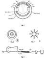
- Fig. 5 shows an electrode configuration according to the invention in which the electrodes substantially are configured circular and circular arc shaped, respectively.
- the electrode configuration shown in Fig. 5 comprises four electrodes E1, E2, E3 and E4, wherein the electrodes E1 and E2 are formed uniformly (for example circular or ellipsoidal) and the electrodes E3 and E4 are formed in a curved manner (for example circular arc shaped, semicircle shaped or spiral arc shaped).
- the circular shaped electrodes E1 and E2 substantially are arranged concentrically with respect to each other.
- the semicircle shaped electrodes E3 and E4 substantially are arranged excentric with respect to the circular shaped electrodes E1 and E2.
- the concentric arrangement of the circular shaped electrodes E1 and E2 substantially corresponds to the parallel arrangement of the electrodes of the electrode configurations shown in Fig. 2a and Fig. 3 .
- the semi-circular shaped electrodes E3 and E4 have a larger radius than the outermost of the two circular shaped electrodes E1 and E2.
- the semi-circular shaped electrodes also may have a smaller radius than the inner one of the two circular shaped electrodes E1 and E2.
- semi-circular shaped electrodes, which have a smaller radius than the inner one of the two circular shaped electrodes E1 and E2 are shown with the reference numerals E3' and E4'.
- the electrode arrangement shown in Fig. 5 may be used for implementing a rotary encoder or a control dial (also known as wheel), for example in order to implement a loudness control in a music playing device.
- a rotary encoder or a control dial also known as wheel
- the thumb may be put onto the electrode configuration and may be moved continuously in circles, i.e. along the electrodes.
- the coverage is detected and measured, respectively, independent of the position and across 360°.
- the position is detected and measured, respectively, with the help of the two semi-circular shaped electrodes E3 and E4 as well as with the help of the circular shaped electrode E1 or E2, wherein the position between 0° and 180° is detected using the electrode E3 and the position between 180° and 360° is detected using the electrode E4. In doing so, an unambiguous measurement of the angle position as well as the detection of a continuous "turning" are provided.
- the layout shown in Fig. 5 corresponds to the layout shown in Fig. 3(a) .
- Fig. 6 shows a further embodiment of an electrode configuration according to the invention comprising substantially circular shaped and semi-circular shaped electrodes, respectively.
- the electrode configuration shown in Fig. 6 substantially comprises at least two electrode configurations according to Fig. 5 arranged into each other.
- a two-dimensional input becomes feasible: a) the detection along the respective electrode configurations (control dial) and b) the detection of the position along an X and Y axis.
- Fig. 7 shows a further exemplary embodiment of an electrode configuration according to the invention, which substantially consists of eight electrode configurations as shown in Fig. 3(a) to Fig. 3(d) .
- the electrode configurations each are arranged in an angle of 45° with respect to each other.
- more or less than eight electrode configurations may be provided.
- the angle may vary.
- six electrode configurations may be provided, which each are arranged in an angle of about 30° relative to one another.
- using the electrode layout shown in Fig. 7 a detection of the position along an X and Y axis is feasible.
- the activation of the electrodes of the electrode configurations according to the invention preferably is not carried out individual, but the electrodes of the electrode configurations are connected to each other such that a reduction of the connections is feasible without interfering with an unambiguous evaluation of the signals.
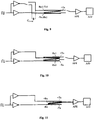
- Fig. 8 to Fig. 11 each show basic circuit diagrams of the electrode configurations (layouts) according to the invention shown in Fig. 3(a) to Fig. 3(d) .
- a square wave generator with, for example, 100 kHz activates two driver components at the outputs of which then generator signals +Tx and -Tx, respectively, shifted in phase by 180°, are present, which are applied to the transmitting electrodes (see table 1 above).
- the measurement signal - a capacitive current or alternating current, respectively, - is tapped at the receiving electrodes, fed to an analog frontend AFE and amplified and conditioned in the analog frontend AFE, for example high- and/or low-pass filtered.
- the amplified and conditioned signal is digitized in an analog to digital converter A/D and processed in a digital signal processing not shown here in detail.
- the electrode configurations according to Fig. 3(a) and Fig. 3(b) have electrodes, which are operated as transmitting or receiving electrodes. At least two measurements are provided for (see table 1 above), for which the respective electrodes then are switched to the respective transmitter and receiver, respectively.
- All of the circuitries shown here are configured such that always two transmitting electrodes are activated at the same time, namely by signals shifted in phase with respect to each other by 180° (i.e. inverted).
- Fig. 8 shows a basic circuit diagram for the electrode configuration of Fig. 3(a) .
- the electrode configuration shown in Fig. 3(a) has the advantage that in the idle mode of the sensor system only one measurement (for detecting the coverage) has to be carried out in order to detect whether a user is approaching the sensor system. Starting from a predetermined minimum coverage (or another suitable threshold value) then a second measurement (for detecting the position) is carried out in order to calculate the position.
- a capacitor C Comp is provided between Rx and -Tx and between -Tx and Rx, respectively.
- the capacitor C Comp may be realized in discrete form or in form of a conductor path coupling. In absolute value, the capacitor C Comp approximately corresponds to the coupling capacity between Tx and Rx in the idle state of the sensor system. By means of providing the capacitor C Comp the measurement signal in the idle state of the sensor system becomes approximately zero, by means of which it is feasible to increase the amplification of the analog frontend AFE and thereby to increase the sensitivity of the sensor. Providing one or more respective capacities C Comp also is feasible in circuitry configured according to the basic circuit diagrams according to Fig. 8 , Fig. 10 and Fig. 11 .
- Fig. 10 shows a basic circuit diagram for the electrode configuration of Fig. 3(c) .
- Fig. 11 shows a basic circuit diagram for the electrode configuration of Fig. 3(d) .
- the above described capacitive sensor systems and electrode configurations as well as modifications according to the invention therefrom may be provided in electric devices, in particular electric handheld devices, in order to equip the handheld device with additional user interfaces and man-machine interfaces, respectively.
- the electric device and electric handheld device respectively may be a smart phone, a mobile radio unit, a computer mouse, a device remote control, a digital camera, a game controller, a mobile mini-computer, a tablet-PC, a dictating machine, a media player or the like.
Description
- The invention relates to an electrode configuration for a capacitive sensor system, in particular for detecting a position of an object relative to the electrode configuration, as well as a method for detecting a position of an object relative to the electrode configuration according to the invention.
- In capacitive sensor systems, in particular capacitive approach sensors, the approach of an object towards a sensor zone substantially is measured contactless by means of generation and measurement of electric alternating fields.
- Derived from the measurement signal may be functions, for example switching functions, of an electric device, in particular an electric handheld device.
- For example, there exists a need to provide sensor zones of a capacitive sensor system at an electric handheld device, wherein during an approach of an object towards a sensor zone not only the approach of the object towards the sensor zone is detectable but also the position of the object relative to the sensor zone.
- Depending on the position of the object relative to the sensor zone different functions may be carried out in the electric handheld device. In doing so, it is desired to achieve a preferably high position resolution. To accomplish that the capacitive sensor system may be used in different electronic devices it is further desired that the capacitive sensor system preferably is independent of the grounding state of the respective electronic device.
- Known from prior art are electrode configurations, in particular for capacitive sensor systems, which function according to the so called loading method, wherein, for example for implementing a sliding controller (in a sliding controller it is important that the position of an object, for example of a finger, may be detected along the sliding controller) a plurality of sensor electrodes arranged side by side and adjacent to each other, respectively, is provided. During operation of the capacitive sensor using a loading method only one sensor electrode is required, which represents a transmitting electrode as well as a receiving electrode.
- US Patent Application Publication
US 2009/0184920 discloses a two element slider with guard sensor. US Patent Application PublicationUS 2011/017523 discloses a single layer touch sensor. US PatentUS 7,218,124 discloses capacitive sensing apparatus designs. US PatentUS 5,136,286 discloses a switched capacitance meter reading device using variable width electrodes. US Patent Application PublicationUS2011/0062971 discloses single layer transcapacitive sensing. - The sensor electrode is loaded with an electric alternating signal, so that an electric alternating field is emitted therefrom, wherein the capacitive load of the sensor electrode (for example by an approach of a finger towards the sensor electrode) is detected and evaluated, respectively, by means of an evaluation device. By means of the detected capacitive load it may be determined at which sensor electrode an approach of the finger has taken place.
- However, such capacitive sensor systems have the disadvantage that very many electrodes are required for a high resolution (position resolution), which significantly increases the constructive effort in the manufacturing process of a sliding controller, for example. In addition, the sensor signal depends on the grounding state of the sensor electronics.
- Furthermore, capacitive sensor systems are known, which also have a large number of sensor electrodes, wherein it is required for an exact detection of the position that, for example, a finger covers several sensor electrodes at the same time when contacting the sensor electrodes. Again, because of the large number of sensor electrodes required for a high position resolution the constructive effort for the manufacturing process is increased significantly.
- It is therefore a goal of the invention to provide an electrode configuration for a capacitive sensor device for detecting a position of an object relative to the electrode arrangement, as well as a method for detecting a position of an object relative to a electrode configuration, which at least partially avoid the disadvantages known from prior art and which allow for a high position resolution with a low number of sensor electrodes, wherein the detection of the position is independent of a grounding state of an electric device for which the capacitive sensor device is provided.
- According to the invention this goal is reached by means of an electrode configuration for a capacitive sensor system and a method for detecting a position of an object relative to an electrode configuration according to the independent patent claims. Advantageous embodiments and improvements of the invention are given in the respective dependent claims. An integral part of the solution also is an electric device, in particular an electric handheld device, which has at least one capacitive sensor system comprising at least one electrode configuration according to the invention.
- According to that, provided is a method for detecting a position of an object relative to an electrode configuration comprising at least three electrodes, wherein a first electrode is arranged parallel or concentrically with respect to a second electrode, a third electrode is arranged in an acute angle or excentric relative to the first electrode, the first electrode is loaded with a first generator signal, and wherein
- for determining a coverage of the electrode configuration by the object the second electrode is operated as receiving electrode and the third electrode may be loaded with a second generator signal, wherein at the receiving electrode a first measurement signal is tapped, which is representative for a first coupling capacity between the receiving electrode and the first electrode, and
- for determining the position the third electrode is operated as a receiving electrode and the second electrode may be loaded with the second generator signal, wherein at the receiving electrode a second measurement signal is tapped, which is representative for a second coupling capacity between the receiving electrode and the first electrode, and wherein the position is determined from the ratio of the variation of the second coupling capacity to the variation of the first coupling capacity.
- Preferably, the second generator signal is inverse with respect to the first generator signal.
- Prior to determining the position it is detected whether the first coupling capacity falls below a predetermined value, wherein the position only then is determined, when the first coupling capacity falls below the predetermined value.
- The variation of the first coupling capacity substantially is proportional to the exposure of the electrode arrangement by the object, and the variation of the second coupling capacity substantially is proportional to the product of coverage and position of the object relative to the electrode arrangement.
- Preferably, the variation of the first coupling capacity and the variation of the second coupling capacity each are determined as a variation with respect to the respective coupling capacity in the basic state of the electrode configuration.
- In addition, provided is an electrode configuration for a capacitive sensor system, in particular for detecting a position of an object relative to the electrode arrangement, wherein the electrode configuration has a first position detection electrode arrangement that comprises a first electrode and a second electrode, wherein the first electrode is operable as a transmitting electrode and the second electrode is operable as a receiving electrode, wherein the first electrode is arranged in an acute angle relative to the second electrode, and wherein the first electrode may be loaded with a first generator signal.
- The electrode configuration further may have at least one coverage detection electrode arrangement, which comprises a third electrode and a fourth electrode, wherein the third electrode may be operated as transmitting electrode and may be loaded with the first generator signal.
- The third electrode of the coverage detection electrode arrangement may be formed by the first electrode of the position detection electrode arrangement (common electrode of the coverage detection electrode arrangement and of the position detection electrode arrangement).
- The electrode configuration further may comprise a second position detection electrode arrangement, which comprises a fifth electrode and a sixth electrode, wherein the fifth electrode is arranged in an acute angle relative to the sixth electrode.
- The second electrode of the first position detection electrode arrangement may be arranged substantially parallel with respect to the fifth electrode of the second position detection electrode arrangement.
- The sixth electrode of the second position detection electrode arrangement is formed by the second electrode of the first position detection electrode arrangement (common electrode of the first position detection electrode arrangement and of the second position detection electrode arrangement), wherein the fifth electrode may be operated as transmitting electrode and may be loaded with the first generator signal.
- The second electrode of the first position detection electrode arrangement substantially may be arranged concentrically with respect to the fifth electrode of the second position detection electrode arrangement.
- The third electrode substantially may be arranged parallel to the fourth electrode.
- The second electrode or the fourth electrode or the sixth electrode may be loaded with a second generator signal, wherein the electrodes not loaded with a generator signal are operable as receiving electrodes.
- Preferably, the second generator signal is formed inverse with respect to the first generator signal.
- The electrode loaded with the first or second generator signal is coupled with at least one receiving electrode via a coupling capacity CComp, wherein the coupling capacity is configured as a discrete capacitor or as a conductor path coupling.
- In an advantageous embodiment of the invention the electrode configuration comprises three electrodes, wherein a first electrode and a second electrode substantially are arranged parallel to one another, and wherein a third electrode is arranged in an acute angle relative to the first electrode and/or the second electrode.
- The third electrode may be arranged between the first electrode and the second electrode, wherein the third electrode is arranged in an acute angle relative to the first electrode and the second electrode.
- In an embodiment the first electrode and the second electrode are operable as transmitting electrodes and the third electrode is operable as receiving electrode, wherein the first electrode may be loaded with a first generator signal and the second electrode may be loaded with a second generator signal.
- In a further embodiment the second electrode and the third electrode are operable as transmitting electrodes and the first electrode is operable as receiving electrode, wherein the second electrode may be loaded with the first generator signal and the third electrode may be loaded with the second generator signal.
- The first generator signal may be inverse with respect to the second generator signal.
- In a further advantageous embodiment of the invention the electrode configuration comprises four electrodes, wherein a first electrode and a second electrode substantially are arranged parallel with respect to each other, wherein a third electrode is arranged in an acute angle relative to the first electrode and/or the second electrode, and wherein a fourth electrode is arranged in an acute angle relative to the third electrode.
- In an embodiment, the second electrode and the fourth electrode are operable as transmitting electrodes and the first electrode is operable as receiving electrode, wherein the second electrode may be loaded with a first generator signal and the fourth electrode may be loaded with a second generator signal.
- In a further embodiment the second electrode and the fourth electrode are operable as transmitting electrodes and the third electrode is operable as receiving electrode, wherein the second electrode may be loaded with the first generator signal and the fourth electrode may be loaded with the second generator signal.
- The first generator signal may be inverse with respect to the second generator signal.
- In a further advantageous embodiment of the invention the electrode configuration comprises four electrodes, wherein a first electrode and a second electrode substantially are arranged parallel to one another, wherein a third electrode is arranged in an acute angle relative to the first electrode, and wherein a fourth electrode is arranged in an acute angle relative to the second electrode. The first electrode and a second electrode are arranged between the third electrode and the fourth electrode.
- In an embodiment the third electrode and the fourth electrode are operable as transmitting electrodes, and the first electrode and the second electrode are operable as receiving electrodes, wherein the third electrode may be loaded with a first generator signal and the fourth electrode may be loaded with a second generator signal.
- The first generator signal may be inverse with respect to the second generator signal.
- In addition, provided by the invention is an electric device, in particular an electric handheld device, which at least comprises a capacitive sensor system that comprises an electrode configuration according to the invention.
- The electric device and the electric handheld device, respectively, may be a smart phone, a mobile radio unit, a computer mouse, a device remote control, a digital camera, a game controller, a mobile mini-computer, a tablet-PC, a dictating machine, a media player or the like.
- Details and characteristics of the invention as well as concrete exemplary embodiments of the invention result from the following description in combination with the drawing.
-
Fig. 1 shows an equivalent circuit diagram of a capacitive sensor system for illustrating the absorption effect; -
Fig. 2a shows a coverage detection electrode arrangement according to the invention for detecting the coverage of the electrodes by an object, for example a finger; -
Fig. 2b shows a position detection electrode arrangement according to the invention for detecting the position of an object relative to the electrodes; -
Figs. 3(a) to 3(d) show different embodiments of an electrode configuration according to the invention (layouts); -
Figs. 4(a) to 4(c) show embodiments according to the invention of the electrodes of an electrode configuration according to the invention; -
Fig. 5 shows an electrode configuration according to the invention, wherein the electrodes substantially are configured circular and semicircle-shaped, respectively; -
Fig. 6 shows a further embodiment of an electrode configuration according to the invention comprising electrodes substantially configured circular and circular arc-shaped, respectively; -
Fig. 7 shows a further embodiment of an electrode configuration according to the invention; and -
Figs. 8 to 11 show basic circuit diagrams for the electrode configurations (layouts) according to the invention shown inFig. 3(a) to Fig. 3(d) . - The sensor system according to the invention for detecting a position of an object relative to an electrode arrangement of the sensor system is configured as a capacitive sensor, which is operated in the operating mode "absorption".
- In addition, the sensor system according to the invention is configured such that the sensor signals of the sensor system provide two informations:
- 1. how large is the sensor surface area of the electrode configuration and how large is the sensor length, respectively, which a user covers with his/her finger, and
- 2. at which position has the user contacted the electrode configuration with his/her finger.
-
Fig. 1 shows an equivalent circuit diagram of a capacitive sensor system for illustrating the absorption effect and for illustrating the measures by which the sensor system is made independent of the grounding state of the sensor system. - The electrodes Tx (transmitting electrode) and Rx (receiving electrode) are arranged adjacent to each other, so that a basic capacitive coupling C12 is formed between them. During an approach of a hand or of a finger F towards the electrodes Tx, Rx the basic capacitive coupling C12 becomes smaller (absorption), so that the electric current flowing through C12 becomes smaller as well.
- The capacitive coupling between the electrode Tx and the finger F is denoted by C1H, the capacitive coupling between Rx and the finger is denoted by C2H. During an approach of the finger F towards the electrodes Tx, Rx the coupling capacities C1H and C2H become larger. Produced from that and parallel to C12 is a current path between the electrode Tx and the electrode Rx that may be interpreted as transmission.
- This current path parallel to C12 has to be reduced, preferably has to be inhibited by means of suitable measures, as described in the following:
- a) It may be attempted to make CHGND (the capacitive coupling between the finger F and ground GND) significantly larger than C1H (or to firmly connect the finger F with ground GND). In doing so, substantially it is achieved that the current flowing from electrode Tx via C1H to finger F does not flow via C2H to electrode Rx. Thereby, the transmission Tx -> Rx is largely avoided, however, the sensor system still depends on the grounding conditions of the sensor system.
- b) In addition, provided is a second transmitting electrode Tx2, which mainly may be brought into a capacitive coupling C3H with the approaching finger F. The second transmitting electrode Tx2 preferably is arranged relative to the receiving electrode Rx such that the capacitive coupling between the second transmitting electrode Tx2 and the receiving electrode Rx is neglectable. The second transmitting electrode Tx2 is loaded with a generator signal, which preferably is inverse with respect to the generator signal applied to the first transmitting electrode Tx. Thereby it is substantially accomplished that the current flowing from electrode Tx via C1H to finger F directly discharges via C3H. A further flow to electrode Rx via C2H of the current flowing from electrode Tx via C1H to finger F such is avoided. In the embodiment of the electrodes it has to be considered that the coupling capacities C1H and C3H substantially are equal. This may be accomplished by an approximately equal electrode width of the first electrode Tx and the second electrode Tx2. In doing so, the sensor system also is independent of the grounding conditions of the sensor system.
- In order to accomplish that the sensor system is largely independent of the grounding state in the preferred embodiment two transmitting electrodes +Tx (in
Fig. 1 denoted by Tx) and -Tx (inFig. 1 denoted by Tx2) are operated at the same time, wherein the transmitting signals and the generator signals, respectively, which are applied to the electrodes +Tx and -Tx, are inverse with respect to each other, i.e. the sum of the alternating portions of the electrode signals +Tx and -Tx equals zero. - By means of the layout of the sensor system and the electrodes, respectively, it is ensured that during contacting the capacitive coupling between +Tx and the finger F of the user ideally is equal in size as the capacitive coupling between -Tx and the finger F. Thereby, the coupling +Tx → F substantially is neutralized by the coupling -Tx → F.
- In non-grounded measurement electronics it is avoided by means of this design that a current flows from the finger of the user to electrode Rx (transmission) and thereby distorts the measurement signal of the absorption.
- In grounded measurement electronics, due to the design, the current flowing from finger F of the user to electrode Rx (transmission) is neglectably small, so that it is ensured that independent of the grounding state no transmission current is flowing. In doing so, the sensor signal is independent of the grounding state. As a result, thereby provided is a capacitive sensor system (position sensor) in operation mode "absorption", which provides approximately equal results with grounded and non-grounded sensor electronics.
- The receiving electrode Rx is designed such and arranged such relative to the transmitting electrodes +Tx, -Tx, respectively, that a capacitive coupling substantially only exists with one of the transmitting electrodes +Tx or -Tx. In an alternative embodiment of the sensor system it also is feasible that the transmission current by means of a respective sensor layout and by means of a respective isolating layer thickness is reduced such that also a sensor system only comprising one transmitting electrode +Tx may be constructed, which is largely independent of the grounding state.
- When the grounding state (grounded or non-grounded) of the sensor system is known and largely constant, the sensor system also may be constructed comprising only one active transmitting electrode +Tx.
- The electrode configuration of a capacitive sensor system according to the invention for detecting a position of an object relative to the electrode configuration substantially comprises two electrode arrangements:
- 1. one coverage detection electrode arrangement, and
- 2. one position detection electrode arrangement.
- With respect to
Fig. 2a and Fig. 2b these two electrode arrangements are described in more detail, before concrete embodiments of electrode configurations according to the invention are described with respect toFig. 3 to Fig. 6 . -
Fig. 2a shows a coverage detection electrode arrangement according to the invention for detecting the coverage of the electrodes by an object, for example a finger. - The coverage detection electrode arrangement comprises two electrodes Tx and Rx, wherein the electrodes Tx, Rx substantially are arranged parallel with respect to each other. The two electrodes Tx, Rx may have the same electrode width. By means of the coverage detection electrode arrangement the electrode length and electrode surface area covered by the finger F may be detected independent of the position of the finger F. Thereby, the sensor signal substantially is proportional to the covered electrode length and electrode surface area, respectively. The electrodes Tx, Rx may be covered with a layer of isolating material.
- When the finger F touches the electrodes Tx, Rx or the surface of the isolating material the coupling capacity between the transmitting electrode Tx and the receiving electrode Rx changes, wherein the variation of the coupling capacity is independent of the position in which the finger approaches the electrodes Tx, Rx and at which position the finger contacts the electrodes Tx, Rx, respectively.
- When the sensor device according to the invention is operated in the absorption mode, then the coupling capacity between the transmitting electrode Tx and the receiving electrode Rx changes and decreases, respectively, according to the following rule:

- The detection of the coverage may also be provided for to switch the sensor device from a first operating mode into a second operating mode, for example from a sleeping mode into an active mode. To do so, a predetermined threshold value may be provided, which has to be exceeded before a change of the operating mode is carried out. For example, the threshold value may include a minimum covering and/or a minimum duration of a coverage.
-
Fig. 2b shows a position detection electrode arrangement according to the invention for detecting the position of an object relative to the electrodes. - The position detection electrode arrangement comprises two electrodes Tx and Rx, wherein the electrodes Tx, Rx substantially are arranged in an acute angle α relative to one another.
- The two electrodes Tx, Rx may have the same electrode width. By means of the position detection electrode arrangement the position P of the finger F relative to the electrodes may be detected depending on the electrode length and electrode surface area, respectively, covered by the finger F. Thereby, the sensor signal substantially is proportional to the covered electrode length and electrode surface area, respectively, as well as substantially proportional to the position P of the finger F. The electrodes Tx, Rx may be covered with a layer of isolating material.
- When the finger F touches the electrodes Tx, Rx or the surface of the isolating material, respectively, the coupling capacity between the transmitting electrode Tx and the receiving electrode Rx at the respective position changes.
- When the sensor device according to the invention is operated in absorption mode, then in the position detection electrode arrangement the coupling capacity between the transmitting electrode Tx and the receiving electrode Rx changes and reduces, respectively, according to the following rule:

- The position is calculated from the quotient ΔC2 / ΔC1 = P * K2/K1. The result of the calculation itself here is independent of the coverage. This means that the position is detected and determined, respectively, in a correct manner independent of the width of the fingers covering the electrodes (finger of a child or finger of an adult), independent of the variation of the width of the covering (for example when the width of an object is changing while the object is moved relative to the electrodes), independent of the distance or a change in distance of the fingers covering the electrodes, and in particular independent of whether a glove is used.
-
Fig. 3 (a) to Fig. 3 (d) show electrode configurations according to the invention, which each comprise at least one position detection electrode arrangement. -
Fig. 3 (a) shows an electrode configuration according to the invention, which is composed of a coverage detection electrode arrangement and a position detection electrode arrangement. By means of the coverage detection electrode arrangement the coverage (length and surface area, respectively, of the coverage) is detected. By means of the position detection electrode arrangement the position of a finger F is detected relative to the electrode configuration. - The coverage detection electrode arrangement is formed by the electrodes E1 and E2. The position detection electrode arrangement is formed by the electrodes E2 and E3. Therefore, the electrode E2 constitutes a common electrode for the coverage detection electrode arrangement and the position detection electrode arrangement.
- In a first measurement the coverage by a finger F is detected. In this connection, the electrode E1 is operated as receiving electrode Rx and the electrodes E2 and E3 each are operated as transmitting electrodes Tx, wherein the electrode E3 is loaded with a generator signal, which is inverse with respect to the generator signal, which is applied to electrode E2.
- In a second measurement the position of the finger F relative to the electrode configuration is detected, wherein in calculating the position the coverage is accounted for (see
formula 2 above). In the second measurement the electrodes E1 and E2 each are operated as a transmitting electrode and the electrode E3 is operated as receiving electrode. The electrode E1 is loaded with a generator signal, which is inverse with respect to the generator signal, which is applied to electrode E2. It may be provided for that the position only then is detected and determined, respectively, when the coverage exceeds a predetermined threshold value. In doing so, the energy consumption may be lowered significantly, which in particular is advantageous in devices and handheld devices, respectively, operated by means of a battery or a rechargeable battery. -
Fig. 3 (b) shows an electrode configuration according to the invention, which is composed of two position detection electrode arrangements. The first position detection electrode arrangement is formed by electrodes E1 and E2, wherein the electrode E1 is arranged in an acute angle with respect to electrode E2. The second position detection electrode arrangement is formed by the electrodes E2 and E3, wherein the electrode E3 is arranged in an acute angle with respect to electrode E2. Therefore, electrode E2 forms a common electrode for the two position detection electrode arrangements. - With the electrode configuration of
Fig. 3 (b) two measurements have to be carried out for detecting the position and the coverage. - In a first measurement the electrode E1 is operated as receiving electrode and the electrodes E2 and E3 are operated as transmitting electrodes. The generator signal applied to electrode E2 is inverse with respect to the generator signal applied to electrode E3. By means of the first measurement a first position POS1 is measured.
- In a second measurement the electrode E3 is operated as receiving electrode and the electrodes E2 and E1 are operated as transmitting electrodes. The generator signal applied to electrode E2 is inverse with respect to the generator signal applied to electrode E1. By means of the second measurement a second position POS2 is measured.
- The coverage results from the rule

- The position of the finger relative to the electrode configuration results from the rule

- Fig. 3 (e) shows an electrode configuration according to the invention, which is composed of two position detection electrode arrangements and one coverage detection electrode arrangement.
- The first position detection electrode arrangement is formed by electrode E1 and E2, wherein electrode E1 is arranged in an acute angle with respect to electrode E2. The second position detection electrode arrangement is formed by electrodes E2 and E3, wherein electrode E3 is arranged in an acute angle with respect to electrode E2. Therefore, electrode E2 forms a common electrode for the two position detection electrode arrangements.
- The coverage detection electrode arrangement is formed by electrodes E3 and E4, wherein electrode E3 substantially is arranged parallel to electrode E4. Therefore, electrode E3 forms a common electrode for the second position detection electrode arrangement and the coverage detection electrode arrangement.
- In a first measurement the coverage of the electrode configuration by a finger F is detected. In this connection, electrode E4 is operated as receiving electrode Rx and electrodes E1 and E3 each are operated as transmitting electrodes Tx, wherein electrode E3 is loaded with a generator signal, which is inverse with respect to the generator signal, which is applied to electrode E1. In doing so, the detection of the coverage substantially is carried out independent of the grounding conditions of the sensor system.
- In a second measurement the position of the finger F relative to the electrode configuration is detected, wherein during the calculation of the position the coverage is accounted for (see
formula 2 above). In the second measurement the electrodes E1 and E3 each are operated as transmitting electrodes and the electrode E2 is operated as receiving electrode. The electrode E1 is loaded with a generator signal, which is inverse with respect to the generator signal, which is applied to electrode E3. It may be provided for that the position only then is detected and determined, respectively, when the coverage exceeds a predetermined threshold value. In doing so, the energy consumption may be reduced significantly, which in particular is advantageous in devices and handheld devices, respectively, operated by a battery or a rechargeable battery. - The electrode configuration shown in
Fig. 3 (c) has the advantage over the electrode configuration shown inFig. 3 (a) that the transmitting electrodes E1 and E3 do not have to be switched in between the measurement of the coverage and the measurement of the position. A further advantage over the electrode configuration ofFig. 3 (a) is that the measurement signal (sensor signal) shows a larger amplitude during the measurement of the position and has a better linearity with respect to the position. -
Fig. 3 (d) shows an electrode configuration according to the invention, which is composed of two position detection electrode arrangements. - The first position detection electrode arrangement is formed by electrodes E1 and E2, wherein electrode E1 is arranged in an acute angle with respect to electrode E2. The second position detection electrode arrangement is formed by electrodes E3 and E4, wherein electrode E3 is arranged in an acute angle with respect to electrode E4. In addition, electrode E2 here substantially is arranged parallel to electrode E3. However, electrode E2 may also be arranged in an acute angle with respect to electrode E3.
- The electrodes E1 and E4 are operated as transmitting electrodes -Tx and +Tx, respectively, during the measurement of the coverage as well as also during the measurement of the position.
- The electrodes E2 and E3 are operated as receiving electrodes -Rx and + Rx, respectively, during the measurement of the coverage as well as also during the measurement of the position. The electrode E1 is loaded with a generator signal, which is inverse with respect to the generator signal, which is applied to electrode E4.
- The coverage of the electrode configuration is determined by means of calculating a difference of the sensor signals tapped at the receiving electrodes E3 and E2 (+Rx and-Rx, respectively), i.e. coverage = (+Rx) - (-Rx). By calculating the difference the immunity to interference is improved for interference signals, which couple into the receiving electrodes E2 and E3 having the same phase.
- The position of a finger relative to the electrode configuration is determined by summing the sensor signals tapped at the receiving electrodes E3 and E2 (+Rx and -Rx, respectively), i.e. position = (+Rx) + (-Rx).
- The activation of the electrodes of the electrode configuration described with respect to
Fig. 3 (a) to Fig. 3 (d) is summarized in the following table:Table 1 Layout Measurement E1 E2 E3 E4 Result Fig. 3(a) 1 Rx +Tx -Tx -- coverage 2 -Tx +Tx Rx -- position Fig. 3(b) 1 Rx +Tx -Tx -- POS1 2 -Tx +Tx Rx -- POS2 Coverage = POS1 + POS2 Position = POS1 - POS2 Fig. 3(c) 1 -Tx -- +Tx Rx coverage 2 -Tx Rx +Tx -- position Fig. 3(d) 1 -Tx -Rx +Rx +Tx Coverage = (+Rx) - (-Rx) 2 -Tx -Rx +Rx +Tx Position = (+Rx) + (-Rx) - By means of the inversely activated transmitting electrodes (-Tx and +Tx) it is accomplished that the sensor system is independent of the concrete grounding conditions of the sensor system.
- The absorption effect substantially takes place between the electrodes Tx/Rx arranged adjacent to each other. The distance of the second Tx electrode to the Rx electrode is larger than the distance of the first Tx electrode to the Rx electrode, so that the effect of the second Tx electrode on the Rx electrode and on the absorption effect, respectively, is neglectably small (and because of the shielding effect of the first Tx electrode).
- In
Fig. 2a to Fig. 3(d) the electrodes of the respective electrode configuration are shown as lines and as thin and substantially rectangular electrodes, respectively. - According to the invention it is also feasible that all or some of the electrodes are formed in a curved manner as shown in
Fig. 4a , for example to linearize the position dependency of the sensor signals or to create a predefined different position dependency. Furthermore it is feasible that all or some of the electrodes are formed in a buckled manner, so that the individual segments of an electrode each have a different acute angle with respect to the adjacent electrode as shown inFig. 4b . - The electrodes also may be configured comprising differing width or a width varying along the length as shown in
Fig. 4c , by means of which substantially the coupling capacity to the finger is influenced. This again influences the ground dependency of the sensor system (Tx to finger) and also the disturbing signal interference of the system (finger to Rx). For an optimal independence from ground the coupling capacities from +Tx to the hand and from -Tx to the hand are equal in size. This may be realized by means of an identical electrode width of +Tx and -Tx. -
Fig. 5 shows an electrode configuration according to the invention in which the electrodes substantially are configured circular and circular arc shaped, respectively. - The electrode configuration shown in
Fig. 5 comprises four electrodes E1, E2, E3 and E4, wherein the electrodes E1 and E2 are formed uniformly (for example circular or ellipsoidal) and the electrodes E3 and E4 are formed in a curved manner (for example circular arc shaped, semicircle shaped or spiral arc shaped). The circular shaped electrodes E1 and E2 substantially are arranged concentrically with respect to each other. The semicircle shaped electrodes E3 and E4 substantially are arranged excentric with respect to the circular shaped electrodes E1 and E2. - The concentric arrangement of the circular shaped electrodes E1 and E2 substantially corresponds to the parallel arrangement of the electrodes of the electrode configurations shown in
Fig. 2a andFig. 3 . The electrodes E1 and E2 shaped in a circular manner and arranged concentrically with respect to one another thereby form a coverage detection electrode arrangement by means of which the coverage may be detected and measured, respectively. - The excentric arrangement of the semi-circular shaped electrodes E3 and E4 relative to the electrodes E1 and E2, respectively, substantially corresponds to the acute angle arrangement of the electrodes of the electrode configurations shown in
Fig. 2b andFig. 3 . The electrodes E3 and E4 shaped in a semi-circular manner and arranged excentric with respect to the electrodes E1 and E2 in each case together with the electrode E2 form a position detection electrode arrangement by means of which the position of an object relative to the electrode configuration may be detected and measured, respectively. - With respect to
Fig. 3(a) to Fig. 3(d) it has been described how the coverage and/or the position may be detected and measured, respectively. - In
Fig. 5 the semi-circular shaped electrodes E3 and E4 have a larger radius than the outermost of the two circular shaped electrodes E1 and E2. Alternatively, the semi-circular shaped electrodes also may have a smaller radius than the inner one of the two circular shaped electrodes E1 and E2. InFig. 5 semi-circular shaped electrodes, which have a smaller radius than the inner one of the two circular shaped electrodes E1 and E2 are shown with the reference numerals E3' and E4'. - In both cases it is advantageous, but not absolutely required, to arrange the semi-circular shaped electrodes E3 and E4 and E3' and E4', respectively, such in a manner relative with respect to the circular shaped electrodes E1 and E2 that they do not intersect the circular shaped electrodes E1 and E2.
- The electrode arrangement shown in
Fig. 5 may be used for implementing a rotary encoder or a control dial (also known as wheel), for example in order to implement a loudness control in a music playing device. For example, in order to operate such a loudness control the thumb may be put onto the electrode configuration and may be moved continuously in circles, i.e. along the electrodes. - In doing so, by means of the electrodes E1 and E2 arranged concentrically with respect to each other the coverage is detected and measured, respectively, independent of the position and across 360°.
- The position is detected and measured, respectively, with the help of the two semi-circular shaped electrodes E3 and E4 as well as with the help of the circular shaped electrode E1 or E2, wherein the position between 0° and 180° is detected using the electrode E3 and the position between 180° and 360° is detected using the electrode E4. In doing so, an unambiguous measurement of the angle position as well as the detection of a continuous "turning" are provided.
- The layout shown in
Fig. 5 corresponds to the layout shown inFig. 3(a) . The layouts shown inFig. 3(b) to Fig. 3(d) accordingly also may be implemented using circular shaped and semi-circular shaped electrodes. -
Fig. 6 shows a further embodiment of an electrode configuration according to the invention comprising substantially circular shaped and semi-circular shaped electrodes, respectively. The electrode configuration shown inFig. 6 substantially comprises at least two electrode configurations according toFig. 5 arranged into each other. By means of arranging the two electrode configurations into each other a two-dimensional input becomes feasible: a) the detection along the respective electrode configurations (control dial) and b) the detection of the position along an X and Y axis. -
Fig. 7 shows a further exemplary embodiment of an electrode configuration according to the invention, which substantially consists of eight electrode configurations as shown inFig. 3(a) to Fig. 3(d) . The electrode configurations each are arranged in an angle of 45° with respect to each other. Of course, also more or less than eight electrode configurations may be provided. Also, the angle may vary. For example six electrode configurations may be provided, which each are arranged in an angle of about 30° relative to one another. Advantageously, using the electrode layout shown inFig. 7 a detection of the position along an X and Y axis is feasible. - The activation of the electrodes of the electrode configurations according to the invention preferably is not carried out individual, but the electrodes of the electrode configurations are connected to each other such that a reduction of the connections is feasible without interfering with an unambiguous evaluation of the signals.
-
Fig. 8 to Fig. 11 each show basic circuit diagrams of the electrode configurations (layouts) according to the invention shown inFig. 3(a) to Fig. 3(d) . - A square wave generator with, for example, 100 kHz activates two driver components at the outputs of which then generator signals +Tx and -Tx, respectively, shifted in phase by 180°, are present, which are applied to the transmitting electrodes (see table 1 above). The measurement signal - a capacitive current or alternating current, respectively, - is tapped at the receiving electrodes, fed to an analog frontend AFE and amplified and conditioned in the analog frontend AFE, for example high- and/or low-pass filtered. The amplified and conditioned signal is digitized in an analog to digital converter A/D and processed in a digital signal processing not shown here in detail.
- The electrode configurations according to
Fig. 3(a) and Fig. 3(b) have electrodes, which are operated as transmitting or receiving electrodes. At least two measurements are provided for (see table 1 above), for which the respective electrodes then are switched to the respective transmitter and receiver, respectively. - All of the circuitries shown here are configured such that always two transmitting electrodes are activated at the same time, namely by signals shifted in phase with respect to each other by 180° (i.e. inverted).
-
Fig. 8 shows a basic circuit diagram for the electrode configuration ofFig. 3(a) . The electrode configuration shown inFig. 3(a) has the advantage that in the idle mode of the sensor system only one measurement (for detecting the coverage) has to be carried out in order to detect whether a user is approaching the sensor system. Starting from a predetermined minimum coverage (or another suitable threshold value) then a second measurement (for detecting the position) is carried out in order to calculate the position. - In the basic circuit diagram of
Fig. 9 , which may be provided for the electrode configuration ofFig. 3(b) , a capacitor CComp is provided between Rx and -Tx and between -Tx and Rx, respectively. - The capacitor CComp may be realized in discrete form or in form of a conductor path coupling. In absolute value, the capacitor CComp approximately corresponds to the coupling capacity between Tx and Rx in the idle state of the sensor system. By means of providing the capacitor CComp the measurement signal in the idle state of the sensor system becomes approximately zero, by means of which it is feasible to increase the amplification of the analog frontend AFE and thereby to increase the sensitivity of the sensor. Providing one or more respective capacities CComp also is feasible in circuitry configured according to the basic circuit diagrams according to
Fig. 8 ,Fig. 10 and Fig. 11 . -
Fig. 10 shows a basic circuit diagram for the electrode configuration ofFig. 3(c) . -
Fig. 11 shows a basic circuit diagram for the electrode configuration ofFig. 3(d) . - The above described capacitive sensor systems and electrode configurations as well as modifications according to the invention therefrom may be provided in electric devices, in particular electric handheld devices, in order to equip the handheld device with additional user interfaces and man-machine interfaces, respectively. The electric device and electric handheld device, respectively may be a smart phone, a mobile radio unit, a computer mouse, a device remote control, a digital camera, a game controller, a mobile mini-computer, a tablet-PC, a dictating machine, a media player or the like.
Claims (15)
- A method for detecting a position (P) of an object (F) relative to an electrode configuration comprising at least three electrodes (El, E2, E3), wherein a first electrode (E2) is arranged substantially parallel or concentrically with respect to a second electrode (E1), a third electrode (E3) is arranged in an acute angle (α) or excentric relative to the first electrode (E2), the first electrode (E2) is loaded with a first generator signal, the method being characterized by:- operating the second electrode (E1) as a receiving electrode and loading the third electrode (E3) with a second generator signal for determining a coverage of the electrode configuration by the object (F), wherein a first measurement signal is received at the receiving electrode (E1), which is representative for a first coupling capacity between the receiving electrode (E1) and the first electrode (E2),- operating the third electrode (E3) as a receiving electrode and loading the second electrode (E1) with the second generator signal for determining the position (P), wherein at the receiving electrode (E3) a second measurement signal is received, which is representative for a second coupling capacity between the receiving electrode (E3) and the first electrode (E2), and wherein the position is determined from the ratio of a change of the second coupling capacity to a change of the first coupling capacity due to the presence of the object (F).
- A method for detecting a position (P) of an object (F) relative to an electrode configuration comprising at least three electrodes (El, E2, E3), wherein a first electrode (E2) is arranged in an acute angle (α) or excentric relative to a second electrode (E1), a third electrode (E3) is arranged substantially parallel or concentrically with respect to the second electrode (E1), the first electrode (E2) is loaded with a first generator signal, the method being characterized by:- operating the second electrode (E1) as a receiving electrode and loading the third electrode (E3) with a second generator signal for determining a coverage of the electrode configuration by the object (F), wherein a first measurement signal is received at the receiving electrode (E1), which is representative for a first coupling capacity between the receiving electrode (E1) and the first electrode (E2),- operating the third electrode (E3) as a receiving electrode and loading the second electrode (E1) with the second generator signal for determining the position (P), wherein at the receiving electrode (E3) a second measurement signal is received, which is representative for a second coupling capacity between the receiving electrode (E3) and the first electrode (E2), and wherein the position is determined from the ratio of a change of the second coupling capacity to a change of the first coupling capacity due to the presence of the object (F).
- The method of claim 1 or 2, wherein the second generator signal is inverse with respect to the first generator signal.
- The method of one of the preceding claims, wherein prior to determining the position it is determined, whether the first coupling capacity falls below a predetermined value, wherein the position only then is determined, when the first coupling capacity falls below the predetermined value.
- The method of one of claims 1 to 4, wherein the change of the first coupling capacity substantially is proportional to the coverage (L) of the electrode configuration by the object (F), and wherein the change of the second coupling capacity substantially is proportional to the product of coverage (L) and position (P) of the object relative to the electrode configuration.
- The method of one of claims 1 to 5, wherein the change of the first coupling capacity and the change of the second coupling capacity each are determined as the change from a respective coupling capacity in an idle state of the electrode configuration.
- A sensor system for detecting a position (P) of an object (F) relative to an electrode configuration comprising at least three electrodes, wherein a first electrode (E2) is arranged substantially parallel or concentrically with respect to a second electrode (E1), a third electrode (E3) is arranged in an acute angle (α) or excentric relative to the first electrode (E2), the first electrode (E2) is loaded with a first generator signal, characterized in that the sensor system is configured to:- operate the second electrode (E1) as a receiving electrode and to load the third electrode (E3) with a second generator signal for determining a coverage of the electrode configuration by the object (F), wherein a first measurement signal received at the receiving electrode (E1) is representative for a first coupling capacity between the receiving electrode (E1) and the first electrode (E2),- operate the third electrode (E3) as a receiving electrode and to load the second electrode (E1) with the second generator signal for determining the position (P), wherein a second measurement signal received at the receiving electrode (E3) is representative for a second coupling capacity between the receiving electrode (E3) and the first electrode (E2), and- to determine the position from a ratio of a change of the second coupling capacity to a change of the first coupling capacity due to the presence of the object (F).
- A sensor system for detecting a position (P) of an object (F) relative to an electrode configuration comprising at least three electrodes, wherein a first electrode (E2) is arranged in an acute angle (α) or excentric relative to a second electrode (E1), a third electrode (E3) is arranged substantially parallel or concentrically with respect to the second electrode (E1), the first electrode (E2) is loaded with a first generator signal, characterized in that the sensor system is configured to:- operate the second electrode (E1) as a receiving electrode and to load the third electrode (E3) with a second generator signal for determining a coverage of the electrode configuration by the object (F), wherein a first measurement signal received at the receiving electrode (E1) is representative for a first coupling capacity between the receiving electrode (E1) and the first electrode (E2),- operate the third electrode (E3) as a receiving electrode and to load the second electrode (E1) with the second generator signal for determining the position (P), wherein a second measurement signal received at the receiving electrode (E3) is representative for a second coupling capacity between the receiving electrode (E3) and the first electrode (E2), and- to determine the position from a ratio of a change of the second coupling capacity to a change of the first coupling capacity due to the presence of the object (F).
- A sensor system for detecting a position (P) of an object (F) relative to an electrode configuration comprising at least four electrodes, wherein a first electrode (E3) is arranged substantially parallel or concentrically with respect to a second electrode (E4), a third electrode (E2) is arranged in an acute angle (α) or excentric relative to the first electrode (E3), and a fourth electrode (E1) is arranged parallel or concentrically with respect to a second electrode (E4) the first electrode (E3) is loaded with a first generator signal and the fourth electrode (E1) is loaded with a second generator signal, characterized in that the sensor system is configured to:- operate the second electrode (E4) as a receiving electrode for determining a coverage of the electrode configuration by the object (F), wherein a first measurement signal received at the second electrode (E4) is representative for a first coupling capacity between the second electrode (E4) and the first electrode (E3),- operate the third electrode (E2) as a receiving electrode for determining the position (P), wherein a second measurement signal received at the third electrode (E2) is representative for a second coupling capacity between the third electrode (E2) and the fourth electrode (E1), and- to determine the position from a ratio of a change of the second coupling capacity to a change of the first coupling capacity due to the presence of the object (F).
- A sensor system for detecting a position (P) of an object (F) relative to an electrode configuration comprising at least four electrodes, wherein a first electrode (E1) is arranged in an acute angle (α) or excentric relative to a second electrode (E2), a third electrode (E4) is arranged substantially parallel or concentrically with respect to the first electrode (E1) and a fourth electrode (E3) is arranged in an acute angle (α) or excentric relative to the third electrode (E4), the first electrode (E1) is loaded with a first generator signal and the third electrode (E4) is loaded with a second generator signal, characterized in that the sensor system is configured to:- operate the second electrode (E2) as a receiving electrode for determining a coverage of the electrode configuration by the object (F), wherein a first measurement signal received at the second electrode (E2) is representative for a first coupling capacity between the second electrode (E2) and the first electrode (E1),- operate the fourth electrode (E3) as a receiving electrode for determining the position (P), wherein a second measurement signal received at the fourth electrode (E3) is representative for a second coupling capacity between the third electrode (E4) and the fourth electrode (E3), and- to determine the position from a ratio of a change of the second coupling capacity to a change of the first coupling capacity due to the presence of the object (F).
- The sensor system of claim 9 or 10, wherein the first and second electrodes each form a circle and the third and fourth electrodes are formed by two semicircles.
- The sensor system of claim 7 or 8, further comprising a square wave generator coupled with a driver and an inverting driver, wherein an output of the driver is coupled with the first electrode (E2) and an output of the inverting driver is configured to be coupled with either the third electrode (E3) or the second electrode (E1).
- The sensor system of one of the preceding claims 7, 8, 9 and 12, further comprising an analog front end circuit (AFE) coupled with a switch configured to couple the analog front end circuit with either the second or the third electrode.
- The electrode configuration of one of the claims 7 to 10, wherein the second generator signal is formed inverse with respect to the first generator signal.
- The electrode configuration of claim 10, further comprising an analog front end circuit (AFE) having a first and a second input, wherein the first input is coupled with the second electrode (E2) and the second input is coupled with the fourth electrode (E3).
Applications Claiming Priority (2)
| Application Number | Priority Date | Filing Date | Title |
|---|---|---|---|
| DE201110083336 DE102011083336A1 (en) | 2011-09-23 | 2011-09-23 | Electrode configuration for position detection and position detection |
| PCT/EP2012/068579 WO2013041645A1 (en) | 2011-09-23 | 2012-09-20 | Electrode configuration for position detection and method for position detection |
Publications (2)
| Publication Number | Publication Date |
|---|---|
| EP2758856A1 EP2758856A1 (en) | 2014-07-30 |
| EP2758856B1 true EP2758856B1 (en) | 2018-06-06 |
Family
ID=47044987
Family Applications (1)
| Application Number | Title | Priority Date | Filing Date |
|---|---|---|---|
| EP12774971.1A Not-in-force EP2758856B1 (en) | 2011-09-23 | 2012-09-20 | Electrode configuration for position detection with capacitive touch sensor and method for position detection |
Country Status (8)
| Country | Link |
|---|---|
| US (1) | US9958532B2 (en) |
| EP (1) | EP2758856B1 (en) |
| JP (1) | JP6035339B2 (en) |
| KR (1) | KR20140069141A (en) |
| CN (1) | CN103827796B (en) |
| DE (1) | DE102011083336A1 (en) |
| TW (1) | TWI564544B (en) |
| WO (1) | WO2013041645A1 (en) |
Families Citing this family (7)
| Publication number | Priority date | Publication date | Assignee | Title |
|---|---|---|---|---|
| DE102011083336A1 (en) | 2011-09-23 | 2013-03-28 | Ident Technology Ag | Electrode configuration for position detection and position detection |
| DE102014218535A1 (en) * | 2014-09-16 | 2016-03-17 | Robert Bosch Gmbh | Capacitive sensor |
| US10108292B2 (en) * | 2015-04-22 | 2018-10-23 | Microchip Technology Incorporated | Capacitive sensor system with multiple transmit electrodes |
| TW201800723A (en) * | 2016-01-27 | 2018-01-01 | 松下知識產權經營股份有限公司 | Sensor and switch including the same |
| KR20190039606A (en) * | 2016-08-30 | 2019-04-12 | 텍추얼 랩스 컴퍼니 | Capacitive sensor |
| WO2019200295A1 (en) * | 2018-04-13 | 2019-10-17 | Tactual Labs Co. | Interior sensing |
| US11937751B2 (en) | 2018-11-09 | 2024-03-26 | Guangdong Midea White Home Appliance Technology Innovation Center Co., Ltd. | Movable electric device |
Citations (2)
| Publication number | Priority date | Publication date | Assignee | Title |
|---|---|---|---|---|
| US5136286A (en) * | 1990-01-29 | 1992-08-04 | Siecor Corporation | Switched capacitance meter reading device using variable width electrodes |
| US20110062971A1 (en) * | 2009-09-11 | 2011-03-17 | Massoud Badaye | Single layer transcapacitive sensing |
Family Cites Families (28)
| Publication number | Priority date | Publication date | Assignee | Title |
|---|---|---|---|---|
| US4879508A (en) * | 1986-04-04 | 1989-11-07 | Mitutoyo Corporation | Capacitance-type measuring device for absolute measurement of positions |
| DE4009977A1 (en) * | 1989-04-04 | 1990-10-11 | Hoerbiger Ventilwerke Ag | Capacitive length or angle measurement arrangement - has transmission, transfer and receiver electrodes giving high degree of linearity |
| US7429262B2 (en) * | 1992-01-07 | 2008-09-30 | Arthrocare Corporation | Apparatus and methods for electrosurgical ablation and resection of target tissue |
| SE470271B (en) | 1992-06-29 | 1993-12-20 | Johansson Ab C E | Scale system for absolute measurement |
| JPH06341805A (en) | 1993-06-02 | 1994-12-13 | S K S Kk | Capacitance type linear scale |
| GB2286247A (en) * | 1994-02-03 | 1995-08-09 | Massachusetts Inst Technology | Capacitive position detection |
| EP1153404B1 (en) * | 1999-01-26 | 2011-07-20 | QRG Limited | Capacitive sensor and array |
| US6815197B2 (en) * | 2001-02-16 | 2004-11-09 | Multi Channel System Mcs Gmbh | Apparatus for conducting electrophysiological measurements on cells |
| EP1754029A1 (en) * | 2004-05-14 | 2007-02-21 | Scientific Generics Limited | Capacitive position sensor |
| US7382139B2 (en) | 2004-06-03 | 2008-06-03 | Synaptics Incorporated | One layer capacitive sensing apparatus having varying width sensing elements |
| US20070132737A1 (en) * | 2005-12-09 | 2007-06-14 | Mulligan Roger C | Systems and methods for determining touch location |
| US7218124B1 (en) * | 2006-01-30 | 2007-05-15 | Synaptics Incorporated | Capacitive sensing apparatus designs |
| GB2437827B (en) | 2006-05-05 | 2008-03-26 | Harald Philipp | Touch screen element |
| TWI444876B (en) * | 2007-04-05 | 2014-07-11 | Qrg Ltd | Two-dimensional position sensor |
| US8581853B2 (en) * | 2007-07-10 | 2013-11-12 | Cypress Semiconductor Corp. | Two element slider with guard sensor |
| US8128620B2 (en) * | 2007-11-13 | 2012-03-06 | St. Jude Medical, Atrial Fibrillation Division, Inc. | Irrigated ablation electrode having proximal direction flow |
| WO2010037758A1 (en) * | 2008-10-01 | 2010-04-08 | Ident Technology Ag | Device and method for tactile and proximity detection |
| US9128543B2 (en) * | 2008-12-11 | 2015-09-08 | Pixart Imaging Inc. | Touch pad device and method for determining a position of an input object on the device using capacitive coupling |
| KR101715013B1 (en) * | 2009-05-13 | 2017-03-10 | 시냅틱스 인코포레이티드 | Capacitive sensor device |
| TWI543048B (en) * | 2009-05-15 | 2016-07-21 | 晨星半導體股份有限公司 | A sensor structure of a capacitive touch panel and the sensing method thereof |
| US7990160B2 (en) * | 2009-05-22 | 2011-08-02 | Synaptics Incorporated | Capacitive sensing with combinatorial sensor layout |
| US8456443B2 (en) | 2009-07-24 | 2013-06-04 | Synaptics Incorporated | Single-layer touch sensors |
| US9753586B2 (en) * | 2009-10-08 | 2017-09-05 | 3M Innovative Properties Company | Multi-touch touch device with multiple drive frequencies and maximum likelihood estimation |
| EP2513763A4 (en) * | 2009-12-18 | 2016-10-05 | Synaptics Inc | Transcapacitive sensor devices with ohmic seams |
| US8710623B1 (en) * | 2010-11-18 | 2014-04-29 | Xilinx, Inc. | Integrated circuit having a discrete capacitor mounted on a semiconductor die |
| US10254873B2 (en) * | 2011-05-05 | 2019-04-09 | Synaptics Incorporated | System and method for determining user input using dual baseline modes |
| US9727176B2 (en) * | 2011-06-21 | 2017-08-08 | Synaptics Incorporated | Capacitive sensor pattern |
| DE102011083336A1 (en) | 2011-09-23 | 2013-03-28 | Ident Technology Ag | Electrode configuration for position detection and position detection |
-
2011
- 2011-09-23 DE DE201110083336 patent/DE102011083336A1/en not_active Withdrawn
-
2012
- 2012-09-19 TW TW101134330A patent/TWI564544B/en not_active IP Right Cessation
- 2012-09-20 WO PCT/EP2012/068579 patent/WO2013041645A1/en active Application Filing
- 2012-09-20 JP JP2014531239A patent/JP6035339B2/en not_active Expired - Fee Related
- 2012-09-20 US US14/346,959 patent/US9958532B2/en not_active Expired - Fee Related
- 2012-09-20 EP EP12774971.1A patent/EP2758856B1/en not_active Not-in-force
- 2012-09-20 KR KR20147009708A patent/KR20140069141A/en not_active Application Discontinuation
- 2012-09-20 CN CN201280046443.3A patent/CN103827796B/en not_active Expired - Fee Related
Patent Citations (2)
| Publication number | Priority date | Publication date | Assignee | Title |
|---|---|---|---|---|
| US5136286A (en) * | 1990-01-29 | 1992-08-04 | Siecor Corporation | Switched capacitance meter reading device using variable width electrodes |
| US20110062971A1 (en) * | 2009-09-11 | 2011-03-17 | Massoud Badaye | Single layer transcapacitive sensing |
Also Published As
| Publication number | Publication date |
|---|---|
| TW201319519A (en) | 2013-05-16 |
| CN103827796B (en) | 2017-06-16 |
| DE102011083336A1 (en) | 2013-03-28 |
| US9958532B2 (en) | 2018-05-01 |
| JP6035339B2 (en) | 2016-11-30 |
| TWI564544B (en) | 2017-01-01 |
| WO2013041645A1 (en) | 2013-03-28 |
| KR20140069141A (en) | 2014-06-09 |
| JP2014531661A (en) | 2014-11-27 |
| US20150123682A1 (en) | 2015-05-07 |
| EP2758856A1 (en) | 2014-07-30 |
| CN103827796A (en) | 2014-05-28 |
Similar Documents
| Publication | Publication Date | Title |
|---|---|---|
| EP2758856B1 (en) | Electrode configuration for position detection with capacitive touch sensor and method for position detection | |
| EP2769471B1 (en) | Electrode device for a capacitive sensor device for position detection | |
| US10310694B2 (en) | Methods and apparatus for a capacitive sensor | |
| US8686969B2 (en) | Input apparatus with integrated detection sections of electromagnetic type and capacitive type | |
| JP2014531661A5 (en) | ||
| EP3405856B1 (en) | Proximity activated gesture | |
| EP2673882B1 (en) | An electrode configuration for a capacitive sensor device and a capacitive sensor device for the detection of an approximation | |
| KR101815042B1 (en) | Method and sensor device for the detection of a gripping of a hand-held device | |
| US20090184920A1 (en) | Two element slider with guard sensor | |
| KR101368971B1 (en) | Minute impedance variation detection device | |
| KR20160070039A (en) | Touch sensing method, touch sensing controller and touch sensing device | |
| JP2014025811A (en) | Capacitance-coupled electrostatic sensor |
Legal Events
| Date | Code | Title | Description |
|---|---|---|---|
| PUAI | Public reference made under article 153(3) epc to a published international application that has entered the european phase |
Free format text: ORIGINAL CODE: 0009012 |
|
| 17P | Request for examination filed |
Effective date: 20140421 |
|
| AK | Designated contracting states |
Kind code of ref document: A1 Designated state(s): AL AT BE BG CH CY CZ DE DK EE ES FI FR GB GR HR HU IE IS IT LI LT LU LV MC MK MT NL NO PL PT RO RS SE SI SK SM TR |
|
| DAX | Request for extension of the european patent (deleted) | ||
| STAA | Information on the status of an ep patent application or granted ep patent |
Free format text: STATUS: EXAMINATION IS IN PROGRESS |
|
| 17Q | First examination report despatched |
Effective date: 20170125 |
|
| RAP1 | Party data changed (applicant data changed or rights of an application transferred) |
Owner name: MICROCHIP TECHNOLOGY GERMANY GMBH |
|
| GRAP | Despatch of communication of intention to grant a patent |
Free format text: ORIGINAL CODE: EPIDOSNIGR1 |
|
| STAA | Information on the status of an ep patent application or granted ep patent |
Free format text: STATUS: GRANT OF PATENT IS INTENDED |
|
| RIC1 | Information provided on ipc code assigned before grant |
Ipc: G06F 3/044 20060101AFI20171219BHEP Ipc: G01D 5/24 20060101ALI20171219BHEP Ipc: G01S 5/02 20100101ALI20171219BHEP Ipc: H03K 17/96 20060101ALI20171219BHEP |
|
| INTG | Intention to grant announced |
Effective date: 20180124 |
|
| GRAS | Grant fee paid |
Free format text: ORIGINAL CODE: EPIDOSNIGR3 |
|
| GRAA | (expected) grant |
Free format text: ORIGINAL CODE: 0009210 |
|
| STAA | Information on the status of an ep patent application or granted ep patent |
Free format text: STATUS: THE PATENT HAS BEEN GRANTED |
|
| AK | Designated contracting states |
Kind code of ref document: B1 Designated state(s): AL AT BE BG CH CY CZ DE DK EE ES FI FR GB GR HR HU IE IS IT LI LT LU LV MC MK MT NL NO PL PT RO RS SE SI SK SM TR |
|
| REG | Reference to a national code |
Ref country code: GB Ref legal event code: FG4D |
|
| REG | Reference to a national code |
Ref country code: CH Ref legal event code: EP Ref country code: AT Ref legal event code: REF Ref document number: 1006814 Country of ref document: AT Kind code of ref document: T Effective date: 20180615 |
|
| REG | Reference to a national code |
Ref country code: IE Ref legal event code: FG4D |
|
| REG | Reference to a national code |
Ref country code: DE Ref legal event code: R096 Ref document number: 602012047207 Country of ref document: DE |
|
| REG | Reference to a national code |
Ref country code: NL Ref legal event code: MP Effective date: 20180606 |
|
| REG | Reference to a national code |
Ref country code: LT Ref legal event code: MG4D |
|
| PG25 | Lapsed in a contracting state [announced via postgrant information from national office to epo] |
Ref country code: LT Free format text: LAPSE BECAUSE OF FAILURE TO SUBMIT A TRANSLATION OF THE DESCRIPTION OR TO PAY THE FEE WITHIN THE PRESCRIBED TIME-LIMIT Effective date: 20180606 Ref country code: SE Free format text: LAPSE BECAUSE OF FAILURE TO SUBMIT A TRANSLATION OF THE DESCRIPTION OR TO PAY THE FEE WITHIN THE PRESCRIBED TIME-LIMIT Effective date: 20180606 Ref country code: ES Free format text: LAPSE BECAUSE OF FAILURE TO SUBMIT A TRANSLATION OF THE DESCRIPTION OR TO PAY THE FEE WITHIN THE PRESCRIBED TIME-LIMIT Effective date: 20180606 Ref country code: NO Free format text: LAPSE BECAUSE OF FAILURE TO SUBMIT A TRANSLATION OF THE DESCRIPTION OR TO PAY THE FEE WITHIN THE PRESCRIBED TIME-LIMIT Effective date: 20180906 Ref country code: FI Free format text: LAPSE BECAUSE OF FAILURE TO SUBMIT A TRANSLATION OF THE DESCRIPTION OR TO PAY THE FEE WITHIN THE PRESCRIBED TIME-LIMIT Effective date: 20180606 Ref country code: CY Free format text: LAPSE BECAUSE OF FAILURE TO SUBMIT A TRANSLATION OF THE DESCRIPTION OR TO PAY THE FEE WITHIN THE PRESCRIBED TIME-LIMIT Effective date: 20180606 Ref country code: BG Free format text: LAPSE BECAUSE OF FAILURE TO SUBMIT A TRANSLATION OF THE DESCRIPTION OR TO PAY THE FEE WITHIN THE PRESCRIBED TIME-LIMIT Effective date: 20180906 |
|
| PG25 | Lapsed in a contracting state [announced via postgrant information from national office to epo] |
Ref country code: RS Free format text: LAPSE BECAUSE OF FAILURE TO SUBMIT A TRANSLATION OF THE DESCRIPTION OR TO PAY THE FEE WITHIN THE PRESCRIBED TIME-LIMIT Effective date: 20180606 Ref country code: GR Free format text: LAPSE BECAUSE OF FAILURE TO SUBMIT A TRANSLATION OF THE DESCRIPTION OR TO PAY THE FEE WITHIN THE PRESCRIBED TIME-LIMIT Effective date: 20180907 Ref country code: LV Free format text: LAPSE BECAUSE OF FAILURE TO SUBMIT A TRANSLATION OF THE DESCRIPTION OR TO PAY THE FEE WITHIN THE PRESCRIBED TIME-LIMIT Effective date: 20180606 Ref country code: HR Free format text: LAPSE BECAUSE OF FAILURE TO SUBMIT A TRANSLATION OF THE DESCRIPTION OR TO PAY THE FEE WITHIN THE PRESCRIBED TIME-LIMIT Effective date: 20180606 |
|
| REG | Reference to a national code |
Ref country code: AT Ref legal event code: MK05 Ref document number: 1006814 Country of ref document: AT Kind code of ref document: T Effective date: 20180606 |
|
| PG25 | Lapsed in a contracting state [announced via postgrant information from national office to epo] |
Ref country code: NL Free format text: LAPSE BECAUSE OF FAILURE TO SUBMIT A TRANSLATION OF THE DESCRIPTION OR TO PAY THE FEE WITHIN THE PRESCRIBED TIME-LIMIT Effective date: 20180606 |
|
| PG25 | Lapsed in a contracting state [announced via postgrant information from national office to epo] |
Ref country code: AT Free format text: LAPSE BECAUSE OF FAILURE TO SUBMIT A TRANSLATION OF THE DESCRIPTION OR TO PAY THE FEE WITHIN THE PRESCRIBED TIME-LIMIT Effective date: 20180606 Ref country code: IS Free format text: LAPSE BECAUSE OF FAILURE TO SUBMIT A TRANSLATION OF THE DESCRIPTION OR TO PAY THE FEE WITHIN THE PRESCRIBED TIME-LIMIT Effective date: 20181006 Ref country code: SK Free format text: LAPSE BECAUSE OF FAILURE TO SUBMIT A TRANSLATION OF THE DESCRIPTION OR TO PAY THE FEE WITHIN THE PRESCRIBED TIME-LIMIT Effective date: 20180606 Ref country code: EE Free format text: LAPSE BECAUSE OF FAILURE TO SUBMIT A TRANSLATION OF THE DESCRIPTION OR TO PAY THE FEE WITHIN THE PRESCRIBED TIME-LIMIT Effective date: 20180606 Ref country code: CZ Free format text: LAPSE BECAUSE OF FAILURE TO SUBMIT A TRANSLATION OF THE DESCRIPTION OR TO PAY THE FEE WITHIN THE PRESCRIBED TIME-LIMIT Effective date: 20180606 Ref country code: PL Free format text: LAPSE BECAUSE OF FAILURE TO SUBMIT A TRANSLATION OF THE DESCRIPTION OR TO PAY THE FEE WITHIN THE PRESCRIBED TIME-LIMIT Effective date: 20180606 Ref country code: RO Free format text: LAPSE BECAUSE OF FAILURE TO SUBMIT A TRANSLATION OF THE DESCRIPTION OR TO PAY THE FEE WITHIN THE PRESCRIBED TIME-LIMIT Effective date: 20180606 |
|
| PG25 | Lapsed in a contracting state [announced via postgrant information from national office to epo] |
Ref country code: SM Free format text: LAPSE BECAUSE OF FAILURE TO SUBMIT A TRANSLATION OF THE DESCRIPTION OR TO PAY THE FEE WITHIN THE PRESCRIBED TIME-LIMIT Effective date: 20180606 Ref country code: IT Free format text: LAPSE BECAUSE OF FAILURE TO SUBMIT A TRANSLATION OF THE DESCRIPTION OR TO PAY THE FEE WITHIN THE PRESCRIBED TIME-LIMIT Effective date: 20180606 |
|
| REG | Reference to a national code |
Ref country code: DE Ref legal event code: R097 Ref document number: 602012047207 Country of ref document: DE |
|
| REG | Reference to a national code |
Ref country code: DE Ref legal event code: R119 Ref document number: 602012047207 Country of ref document: DE |
|
| PLBE | No opposition filed within time limit |
Free format text: ORIGINAL CODE: 0009261 |
|
| STAA | Information on the status of an ep patent application or granted ep patent |
Free format text: STATUS: NO OPPOSITION FILED WITHIN TIME LIMIT |
|
| PG25 | Lapsed in a contracting state [announced via postgrant information from national office to epo] |
Ref country code: MC Free format text: LAPSE BECAUSE OF FAILURE TO SUBMIT A TRANSLATION OF THE DESCRIPTION OR TO PAY THE FEE WITHIN THE PRESCRIBED TIME-LIMIT Effective date: 20180606 |
|
| REG | Reference to a national code |
Ref country code: CH Ref legal event code: PL |
|
| 26N | No opposition filed |
Effective date: 20190307 |
|
| GBPC | Gb: european patent ceased through non-payment of renewal fee |
Effective date: 20180920 |
|
| PG25 | Lapsed in a contracting state [announced via postgrant information from national office to epo] |
Ref country code: DK Free format text: LAPSE BECAUSE OF FAILURE TO SUBMIT A TRANSLATION OF THE DESCRIPTION OR TO PAY THE FEE WITHIN THE PRESCRIBED TIME-LIMIT Effective date: 20180606 Ref country code: SI Free format text: LAPSE BECAUSE OF FAILURE TO SUBMIT A TRANSLATION OF THE DESCRIPTION OR TO PAY THE FEE WITHIN THE PRESCRIBED TIME-LIMIT Effective date: 20180606 |
|
| REG | Reference to a national code |
Ref country code: BE Ref legal event code: MM Effective date: 20180930 |
|
| REG | Reference to a national code |
Ref country code: IE Ref legal event code: MM4A |
|
| PG25 | Lapsed in a contracting state [announced via postgrant information from national office to epo] |
Ref country code: LU Free format text: LAPSE BECAUSE OF NON-PAYMENT OF DUE FEES Effective date: 20180920 |
|
| PG25 | Lapsed in a contracting state [announced via postgrant information from national office to epo] |
Ref country code: DE Free format text: LAPSE BECAUSE OF NON-PAYMENT OF DUE FEES Effective date: 20190402 Ref country code: IE Free format text: LAPSE BECAUSE OF NON-PAYMENT OF DUE FEES Effective date: 20180920 |
|
| PG25 | Lapsed in a contracting state [announced via postgrant information from national office to epo] |
Ref country code: BE Free format text: LAPSE BECAUSE OF NON-PAYMENT OF DUE FEES Effective date: 20180930 Ref country code: FR Free format text: LAPSE BECAUSE OF NON-PAYMENT OF DUE FEES Effective date: 20180930 Ref country code: LI Free format text: LAPSE BECAUSE OF NON-PAYMENT OF DUE FEES Effective date: 20180930 Ref country code: CH Free format text: LAPSE BECAUSE OF NON-PAYMENT OF DUE FEES Effective date: 20180930 |
|
| PG25 | Lapsed in a contracting state [announced via postgrant information from national office to epo] |
Ref country code: GB Free format text: LAPSE BECAUSE OF NON-PAYMENT OF DUE FEES Effective date: 20180920 |
|
| PG25 | Lapsed in a contracting state [announced via postgrant information from national office to epo] |
Ref country code: AL Free format text: LAPSE BECAUSE OF FAILURE TO SUBMIT A TRANSLATION OF THE DESCRIPTION OR TO PAY THE FEE WITHIN THE PRESCRIBED TIME-LIMIT Effective date: 20180606 |
|
| PG25 | Lapsed in a contracting state [announced via postgrant information from national office to epo] |
Ref country code: MT Free format text: LAPSE BECAUSE OF NON-PAYMENT OF DUE FEES Effective date: 20180920 |
|
| PG25 | Lapsed in a contracting state [announced via postgrant information from national office to epo] |
Ref country code: TR Free format text: LAPSE BECAUSE OF FAILURE TO SUBMIT A TRANSLATION OF THE DESCRIPTION OR TO PAY THE FEE WITHIN THE PRESCRIBED TIME-LIMIT Effective date: 20180606 |
|
| PG25 | Lapsed in a contracting state [announced via postgrant information from national office to epo] |
Ref country code: HU Free format text: LAPSE BECAUSE OF FAILURE TO SUBMIT A TRANSLATION OF THE DESCRIPTION OR TO PAY THE FEE WITHIN THE PRESCRIBED TIME-LIMIT; INVALID AB INITIO Effective date: 20120920 Ref country code: PT Free format text: LAPSE BECAUSE OF FAILURE TO SUBMIT A TRANSLATION OF THE DESCRIPTION OR TO PAY THE FEE WITHIN THE PRESCRIBED TIME-LIMIT Effective date: 20180606 |
|
| PG25 | Lapsed in a contracting state [announced via postgrant information from national office to epo] |
Ref country code: MK Free format text: LAPSE BECAUSE OF NON-PAYMENT OF DUE FEES Effective date: 20180606 |