EP2758692B2 - Drum lagging material and installation method therefor - Google Patents
Drum lagging material and installation method therefor Download PDFInfo
- Publication number
- EP2758692B2 EP2758692B2 EP12778511.1A EP12778511A EP2758692B2 EP 2758692 B2 EP2758692 B2 EP 2758692B2 EP 12778511 A EP12778511 A EP 12778511A EP 2758692 B2 EP2758692 B2 EP 2758692B2
- Authority
- EP
- European Patent Office
- Prior art keywords
- lagging material
- coated
- drum
- lagging
- seaming
- Prior art date
- Legal status (The legal status is an assumption and is not a legal conclusion. Google has not performed a legal analysis and makes no representation as to the accuracy of the status listed.)
- Active
Links
- 239000000463 material Substances 0.000 title claims description 181
- 238000009434 installation Methods 0.000 title claims description 38
- 238000000034 method Methods 0.000 title claims description 27
- 238000004826 seaming Methods 0.000 claims description 49
- 238000000576 coating method Methods 0.000 claims description 24
- 239000011248 coating agent Substances 0.000 claims description 19
- 239000000758 substrate Substances 0.000 claims description 19
- 239000004744 fabric Substances 0.000 claims description 13
- 239000000853 adhesive Substances 0.000 claims description 9
- 230000001070 adhesive effect Effects 0.000 claims description 9
- 239000003292 glue Substances 0.000 claims description 8
- 229920001971 elastomer Polymers 0.000 claims description 6
- 229910000831 Steel Inorganic materials 0.000 claims description 5
- 239000010959 steel Substances 0.000 claims description 5
- 208000019300 CLIPPERS Diseases 0.000 claims description 4
- 208000021930 chronic lymphocytic inflammation with pontine perivascular enhancement responsive to steroids Diseases 0.000 claims description 4
- 239000000835 fiber Substances 0.000 claims description 4
- 239000011087 paperboard Substances 0.000 claims description 4
- 229920001296 polysiloxane Polymers 0.000 claims description 2
- 229920002635 polyurethane Polymers 0.000 claims description 2
- 239000004814 polyurethane Substances 0.000 claims description 2
- 239000012209 synthetic fiber Substances 0.000 claims description 2
- 229920002994 synthetic fiber Polymers 0.000 claims description 2
- 229920001187 thermosetting polymer Polymers 0.000 claims description 2
- 230000003068 static effect Effects 0.000 claims 3
- 238000003780 insertion Methods 0.000 claims 2
- 230000037431 insertion Effects 0.000 claims 2
- 239000000806 elastomer Substances 0.000 claims 1
- 229920001169 thermoplastic Polymers 0.000 claims 1
- 239000004416 thermosoftening plastic Substances 0.000 claims 1
- 239000000123 paper Substances 0.000 description 20
- 229910000746 Structural steel Inorganic materials 0.000 description 12
- 238000004519 manufacturing process Methods 0.000 description 6
- 229920002472 Starch Polymers 0.000 description 3
- 238000001816 cooling Methods 0.000 description 3
- 235000019698 starch Nutrition 0.000 description 3
- 239000008107 starch Substances 0.000 description 3
- 238000004026 adhesive bonding Methods 0.000 description 2
- 239000004568 cement Substances 0.000 description 2
- 230000001419 dependent effect Effects 0.000 description 2
- 238000005259 measurement Methods 0.000 description 2
- 241000274582 Pycnanthus angolensis Species 0.000 description 1
- 230000002411 adverse Effects 0.000 description 1
- 238000010438 heat treatment Methods 0.000 description 1
- 238000011900 installation process Methods 0.000 description 1
- 238000005304 joining Methods 0.000 description 1
- 239000004745 nonwoven fabric Substances 0.000 description 1
- 238000004806 packaging method and process Methods 0.000 description 1
- 230000000737 periodic effect Effects 0.000 description 1
- 239000012815 thermoplastic material Substances 0.000 description 1
- 238000011144 upstream manufacturing Methods 0.000 description 1
- 238000003466 welding Methods 0.000 description 1
Images


Classifications
-
- B—PERFORMING OPERATIONS; TRANSPORTING
- B31—MAKING ARTICLES OF PAPER, CARDBOARD OR MATERIAL WORKED IN A MANNER ANALOGOUS TO PAPER; WORKING PAPER, CARDBOARD OR MATERIAL WORKED IN A MANNER ANALOGOUS TO PAPER
- B31F—MECHANICAL WORKING OR DEFORMATION OF PAPER, CARDBOARD OR MATERIAL WORKED IN A MANNER ANALOGOUS TO PAPER
- B31F1/00—Mechanical deformation without removing material, e.g. in combination with laminating
- B31F1/20—Corrugating; Corrugating combined with laminating to other layers
- B31F1/24—Making webs in which the channel of each corrugation is transverse to the web feed
- B31F1/30—Tools secured to endless chains, e.g. toothed belts; combined with uniting the corrugated web to flat webs
-
- F—MECHANICAL ENGINEERING; LIGHTING; HEATING; WEAPONS; BLASTING
- F16—ENGINEERING ELEMENTS AND UNITS; GENERAL MEASURES FOR PRODUCING AND MAINTAINING EFFECTIVE FUNCTIONING OF MACHINES OR INSTALLATIONS; THERMAL INSULATION IN GENERAL
- F16G—BELTS, CABLES, OR ROPES, PREDOMINANTLY USED FOR DRIVING PURPOSES; CHAINS; FITTINGS PREDOMINANTLY USED THEREFOR
- F16G3/00—Belt fastenings, e.g. for conveyor belts
- F16G3/16—Devices or machines for connecting driving-belts or the like
-
- F—MECHANICAL ENGINEERING; LIGHTING; HEATING; WEAPONS; BLASTING
- F16—ENGINEERING ELEMENTS AND UNITS; GENERAL MEASURES FOR PRODUCING AND MAINTAINING EFFECTIVE FUNCTIONING OF MACHINES OR INSTALLATIONS; THERMAL INSULATION IN GENERAL
- F16C—SHAFTS; FLEXIBLE SHAFTS; ELEMENTS OR CRANKSHAFT MECHANISMS; ROTARY BODIES OTHER THAN GEARING ELEMENTS; BEARINGS
- F16C2223/00—Surface treatments; Hardening; Coating
- F16C2223/30—Coating surfaces
- F16C2223/32—Coating surfaces by attaching pre-existing layers, e.g. resin sheets or foils by adhesion to a substrate; Laminating
-
- Y—GENERAL TAGGING OF NEW TECHNOLOGICAL DEVELOPMENTS; GENERAL TAGGING OF CROSS-SECTIONAL TECHNOLOGIES SPANNING OVER SEVERAL SECTIONS OF THE IPC; TECHNICAL SUBJECTS COVERED BY FORMER USPC CROSS-REFERENCE ART COLLECTIONS [XRACs] AND DIGESTS
- Y10—TECHNICAL SUBJECTS COVERED BY FORMER USPC
- Y10T—TECHNICAL SUBJECTS COVERED BY FORMER US CLASSIFICATION
- Y10T29/00—Metal working
- Y10T29/49—Method of mechanical manufacture
- Y10T29/49826—Assembling or joining
-
- Y—GENERAL TAGGING OF NEW TECHNOLOGICAL DEVELOPMENTS; GENERAL TAGGING OF CROSS-SECTIONAL TECHNOLOGIES SPANNING OVER SEVERAL SECTIONS OF THE IPC; TECHNICAL SUBJECTS COVERED BY FORMER USPC CROSS-REFERENCE ART COLLECTIONS [XRACs] AND DIGESTS
- Y10—TECHNICAL SUBJECTS COVERED BY FORMER USPC
- Y10T—TECHNICAL SUBJECTS COVERED BY FORMER US CLASSIFICATION
- Y10T29/00—Metal working
- Y10T29/53—Means to assemble or disassemble
Definitions
- corrugated paper board or box board
- corrugator machines An exemplary description of corrugator machines and their use can be found in U.S. Patent No. 6,276,420 .
- a so-called core paper is heated by steam, which makes it more pliable, and is then fed into a nip formed between a pair of toothed rollers whose teeth mesh, thereby corrugating the core paper in a uniform, undulating pattern.
- Starch paste is subsequently applied to the crests of the corrugated core paper, which is then mated to a liner paper in a roll nip. There, the corrugated core paper and liner paper are bonded together to form a completed sheet, which can then be further processed as desired.
- the nip is formed by one of the toothed or corrugating rolls and a pressure roll.
- the nip is extended in the running direction through the use of a belt instead of a pressure roll.
- the belt holds the corrugated core paper and liner paper together against the corrugating roll for a significant portion of its circumference.
- corrugator belts pull a continuous sheet of corrugated board first through a heating zone, where an adhesive used to bond layers of the continuous sheet together is dried or cured, and then through a cooling zone. The board is subsequently cut and processed into the desired shape to be used for making boxes. Frictional forces between the corrugator belt, specifically the face, or board, side thereof, and the continuous sheet are primarily responsible for pulling the latter through the machine. Corrugator belts must travel around cylindrical pulleys or drums in operation. Some of these drums are driven, which moves the corrugator belt through the machine as well as the corrugated board formed thereon in a continuous manner. A lagging material covers the drive drum surface in order to, among other things, keep the belt from slipping.
- prior art lagging materials are manufactured in endless form and are typically uncoated or coated on one surface. Also, prior art lagging materials are installed on a drum by adhesive bonding, that is, using a very strong rubber contact cement like 3M 1300L, which adheres to the lagging material and to the drum surface. This lagging material is used to provide friction between the belt and driver roll in order to pull the belt and board through the machine section. There are many variations of lagging material, for example, woven lagging material, some rubber lagging material, lagging materials having different shaped surfaces, and so on. None of the prior art lagging structures have a seam or are on-machine seamable as the gluing process does not require it.
- Prior art glued lagging materials must be replaced from time to time, either periodically (e.g., annually) or for other reasons. To replace it, a crew of people has to grind, scrape, and remove all the lagging material and glue off the drum to allow the new glue and lagging to be installed. In most cases, this requires several days of work and machine downtime.
- Document GB470261 discloses an on machine attachable material for use on a cylindrical drum for an industrial machine. The material is attached on the drum using a seaming element.
- Document FR2628453 discloses a seamable fabric for use on a drum of a paper production machine, the fabric comprising a seaming element in the form of loops joined by a pin along a cross-machine direction of each of the opposing ends of the fabric for forming a seam for seaming opposing ends of the fabric when brought together.
- Document FR2628453 further discloses a method to install a fabric on a drum of a paper production machine, the method comprising: positioning the fabric on the drum; attaching an installation device on opposing end of the fabric; bringing the ends of the fabric into a seaming position with the installation apparatus; and seaming the fabric onto the drum.
- an on machine seamable lagging material is defined by claim 1.
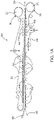
- FIGs 1A and 1B are schematic views of a typical belted section of a corrugator machine.
- a corrugator machine 50 in Figure 1A has an upper corrugator belt 52 and a lower corrugator belt 54 which together support and pull a corrugated paper product 56 therethrough.
- the upper and lower belts 52, 54 together pull the corrugated paper product 56 between them, maintaining the speed of the operation and cooling the paper product 56.
- Weighted rollers 66 apply pressure from within the endless loops formed by belt 52 and belt 54 toward one another, so that corrugated paper product 56 may be held therebetween firmly as the starch based adhesive (applied upstream from the present section) cures.
- the corrugated paper product 56 is cut and/or stacked or further processed as required.
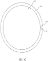
- Drums 25 have lagging material (not shown) installed on their surface.
- Figure 1B shows a doublebacker section in which the upper belt 52 is replaced with a much shorter corrugator belt 72.
- the upper belt 72 does not pass across the hot plates 62. Instead, the upper belt 72 is disposed opposite the lower belt 54 downstream from hot plates 62 in what may be referred to as cooling, or pulling, zone 74.
- cooling, or pulling, zone 74 In this variety of corrugator machine 70, weighted steel shoes push the corrugated paper product 56 against the hot plates 62.
- the upper and lower belts 72, 54 disposed downstream from hot plates 62 pull the corrugated paper product 56 through the machine 70.
- weighted rollers 66 apply pressure from within the endless loops formed by belt 72 and belt 54 toward one another, so that corrugated paper product 56 is firmly held therebetween as the starch based adhesive cures.
- the corrugated paper product 56 is cut and/or stacked.
- Drums 25 have lagging material (not shown) installed on their surface.
- corrugator machines place the belts, and hence the drive drums 25 and pulleys, under highly stressful and adverse conditions.
- the belts 52, 54, 74 to operate properly must move at the speed of the drum surface as the belt and board move through the section. This is achieved by applying lagging to the drum surface (s), lagging being a material that wraps around the drum surface and provides sufficient friction between the belt's inner surface (nonsheet surface) and the lagging to prevent the belt from slipping.
- a lagging sufficiently elastic in the machine direction (MD) and having other properties, such that it does not require adhesives such as those above to maintain grip on a drum, and an installation apparatus therefor.
- a double coated lagging material with a coating on both the drum surface side (inside) and the belt contact side (outside), such that the inside coating has a Coefficient of Friction to prevent the lagging, once stretched and seamed, from slipping on the drum surface.
- embodiments show a double-sided lagging, as the inside coating has a Coefficient of Friction to prevent the lagging from the slipping on the drum surface, embodiments also include a lagging material with a coating on only the drum surface side (inside), and not on the paper belt side.
- the single or double-coated lagging prevents the lagging from slipping on the drum and also prevents (or at least minimize) the belt from slipping on the lagging.
- a coated lagging can have a Coefficient of Friction of about 7 times greater than that of a conventional lagging, as shown in the Table 1.
- lagging it is advantageous to have, among other things, an efficient and effective way to install the lagging on the drum without glue adhesive.
- lagging is replaced on a periodic basis due to wear or for other reasons.
- a crew of people have to grind, scrape, and remove all the material off the roll/drum to allow the new glue and lagging to be installed. In most cases, this requires several days to accomplish while the machine is down and out of operation.
- the lagging material is configured to be a lagging for a corrugator machine drive roll/drum in the manufacture of corrugated packaging board.
- lagging there are many variations of lagging, some woven, some woven with needled batt, some coated on the belt (or non drum) surface contact side; however no conventional lagging material has a cross-machine direction (CD) seam or is made to be on machine seamable.
- CD cross-machine direction
- a lagging sufficiently elastic in the machine direction and having other properties such that it does not require strong adhesives or glue to remain on the surface of the drum 25 during operation.
- a lagging including a double coated 19, 20 substrate 17, 18, with a coating 19, 20 on both sides of the lagging material 10, such that the Coefficient of Friction of the stretched lagging is sufficient for the lagging to remain in place on the exterior drum surface during operation of the machine and to prevent the corrugator belt from slipping on the drive drum while moving through the corrugator machine.
- the coatings 19, 20 can include thermoset or thermoplastic material.
- the coating on the outer surface 19 can be the same as that of the drum-contact surface 20, or can be different (i.e., a functional coating chosen for desired qualities for the inner/outer surfaces).
- Coatings 19, 20 can include elastomeric coatings selected from a polyurethane, a rubber, silicone, and other known materials (or combinations thereof).
- a lagging in another embodiment, shown at FIG. 2A , includes a lagging material 10 including a substrate 18 with a single coating 20 on only the drum surface side (inside).
- FIGS. 2A and 2B are exemplary embodiments of a double coated lagging material and single coated lagging material respectively, and the number of substrate layers, materials can vary in other embodiments.
- specifications for a lagging material can be configured for use on industrial machines as described herein.
- Exemplary weights and caliper ranges for embodiments of the lagging including (1) an uncoated substrate, (2) a single coated lagging coated only on the drum contact side, or (3) double coated on the drum contact side and sheet contact side are given in Table 2 as follows.
- the higher end of the range is elevated as there may be some machines that may need a thicker belt on one of the drive rolls so that the effective diameter (e.g., diameter of the roll together with thicknesses of the lagging and the corrugator belt) of the two drive rolls are the same and they pull the corrugator board at the same speed.
- effective diameter e.g., diameter of the roll together with thicknesses of the lagging and the corrugator belt
- a lagging material 10 of FIG. 2 can be a woven substrate with needled batt fiber 17, 18 formed from 100% percent synthetic fibers and yarns.
- specifications of a lagging can be, for example, the uncoated lagging material can be at a weight of about 7 oz/ft2 (2.1 kg/m2) and a thickness of about 0.180 inches (4.6 mm), the single coated lagging can weigh about 11.7 oz/ft2 (3.6 kg/m2 )and the thickness is about 0.213 inches (5.4 mm), and the double coated lagging can weigh about 16.8 oz/ft2 (5.1 kg/m2) and the thickness is about 0.245 inches (6.2 mm).
- a seamable lagging material can be configured to be installed for use on a cylindrical pulley or drum for an industrial machine.
- the lagging material 10 is made seamable for easy installation and removal from a drum 25.
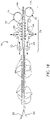
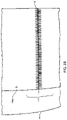
- FIGS. 3A , 3B and 3C are a respectively a perspective view, a top view and a side view of the lagging material 10 as installed on a drum 25.
- the lagging material comprises a seaming area 13 for seaming opposing ends 11, 12 of a lagging material 10 when brought together.
- the seam area 13 is shown as a clipper hook seam 16, however as will be appreciated, the seam 16 can include seaming methods or elements known in the art of industrial fabrics, such as clipper hook seams, spiral-links, and pin-seams wherein the yarns of the substrate actually form seaming loops themselves, or any other seaming method such that the seaming elements for each edge of the lagging can be interdigitated, forming a tunnel in which a pin or pintle 17 can be inserted therein.
- seaming methods or elements known in the art of industrial fabrics such as clipper hook seams, spiral-links, and pin-seams wherein the yarns of the substrate actually form seaming loops themselves, or any other seaming method such that the seaming elements for each edge of the lagging can be interdigitated, forming a tunnel in which a pin or pintle 17 can be inserted therein.
- FIGS. 4A and 4C are respectively a perspective view and plan view of an installation device 1 for installing a seamable lagging material 10 onto a drum surface.
- the apparatus comprises two opposed elongate members 2, 3 each elongate member 2, 3 being structured to be placed longitudinally along the cross-machine direction (CD) of a drum 25 over opposing sides of a seaming area 13 for a seam 16 of a lagging material 10 for installation of the lagging material 10 on the drum 25.
- the elongate members 2, 3 can be substantially the same width as the cross-machine direction (CD) width of the lagging material 10 itself.
- the elongate member can be about 24 inches (610 mm), which is the cross-machine direction (CD) size/dimension for such a lagging.
- corrugator machines can have drums of cross-machine direction (CD) widths of 5 meters(approximately 200 inches) or more.
- the installation tool can be configured to the desired cross-machine direction (CD) width for any lagging size 10, including up to a cross-machine direction (CD) width where a "full size" lagging 10 can be installed in one piece on a drum 25.
- CD cross-machine direction
- each elongate member comprises a base portion 2a, 3a and an upright portion 2b, 3b, such as an angle iron as is shown.
- each elongate member is aligned in the cross-machine direction (CD) and placed over each end 11, 12 of a flat (non-continuous and unseamed) lagging 10 that is wrapped around a drum 25 for installation thereon.
- the base of the angle iron is placed along the cross-machine direction (CD) on the drum over one joining end 11 of the lagging 10, and the upright portion 2b, 3b of the angle iron stands substantially perpendicular to the drum.
- Each elongate member 2 is configured to be substantially laterally paired in the machine direction (MD) with an opposing elongate member 3 around the seam area 13 when installing the lagging material 10 on the drum 25.
- MD machine direction
- the elongate member is shown as an angle iron, other embodiments are contemplated.
- a rod or planar element could be structured to act as an installation apparatus.
- a plurality of lagging material engagement members 4, 5 can be attached to each opposed elongate member 2, 3.
- a plurality of hook elements 4a , 4b, 4c, 5a, 5b, 5c are attached to each respective elongate member 2, 3.
- the hooks are attached to the bottom upper surface of the base 2a, 3a of the elongate member 2, 3 as the plurality of hook elements 4a, 4b, 4c 5a, 5b, 5c are each attached to the angle iron 2,3.
- FIG 4B is a plan view showing the elongate member 2 further comprising an angle iron; and the plurality of hook elements 4a, 4b, 4c are each attached to the angle iron 2.
- the plurality of hook elements 4a, 4b, 4c are each attached to the angle iron 2.
- three 6 inch by 1/8 inch (152 mm by 3.12 mm) hooks 4a, 4b, 4c are welded to the bottom of the angle iron 2, which gives sufficient strength to withstand the tensile strain on the apparatus 1 when installing the lagging material 10 onto the drum, as described herein.
- engagement devices 4, 5 can be employed, such as clasps. Also, any number of techniques may be used to attach engagement devices 4, 5 such as welding, screwing, or hooking to an elongated member 2, 3.
- the lagging material engagement members 4, 5 are spaced at substantially regular intervals along the cross-machine direction (CD) of each of the elongate members 2, 3.
- the substantially regular intervals as described herein account for differentials in the intervals for various embodiments.
- the middle engagement member 4b can be somewhat off-center by a measurement sufficient to allow a tensioning member 8 to be operatively included in the installation apparatus.
- the space between engagement member 4a and engagement member 4b can be from about 9 to about 11 inches (from about 228 mm to about 279 mm), and the space between engagement member 4b and engagement member 4c can be from about 15 to about 13 inches (from about 381 mm to about 330 mm).
- this allows for an offset 28 of from about 1 to about 3 inches (25 to about 76 mm) between engagement members which are paired in the machine direction (MD) as described below and shown clearly in FIG. 4C .
- Each lagging material engagement member 4, 5 is positioned to engage the seaming area 13 at corresponding openings 14, 15 on the lagging material 10.
- one elongate member 2 has three hooks 4a, 4b, 4c, each of which are positioned to engage one end 11 of the lagging material at corresponding openings 14a, 14b, 14c on the lagging material 10.
- the hooks 4a, 4b, 4c spaced at substantially regular intervals along the cross-machine direction (CD) of the lagging material 10.
- the opposing elongate member 3 has three hooks 5a, 5b, 5c, each of which are positioned to engage an opposing end 12 of the lagging material at corresponding openings 15a, 15b, 15c on the lagging material 10.
- the hooks 4a, 4b, 4c and 5a, 5b, 5c are spaced at substantially regular intervals of each elongate member along the cross-machine direction (CD).
- the corresponding openings 14a, 14b, 14c and 15a, 15b, 15c are also spaced at substantially regular intervals along the cross-machine direction (CD) of the ends of the lagging material 11, 12. This configuration causes the ends of the lagging material 11, 12 to come together and meet in the seaming area 13 when the installation apparatus is employed, as discussed herein.
- each lagging material engagement member 4a, 4b, 4c on one elongate member 2 is substantially laterally paired in the machine direction (MD) with an opposing lagging material engagement 5a, 5b, 5c member on the opposing elongate member 3.
- hook 4a is paired in the machine direction (MD) with hook 5a
- hook 4b is paired in the machine direction (MD) with hook 5b
- hook 4c is pared in the machine direction (MD) with 5c.
- each opening 14, 15 is substantially laterally paired in the machine direction (MD) with an opposing opening 14a, 14b, 14c member on the lagging material 10 when the lagging material is wrapped around a drum 25 for installation thereon.
- opening 14a is paired in the machine direction (MD) with hook 15a
- opening 14b is paired in the machine direction (MD) with hook 15b
- opening 14c is paired in the machine direction (MD) with 15c.
- a pairing in the machine direction (MD) allows for some differential, as for example between engagement members 4b and 5b, which have an offset 28 in the cross machine direction (CD) to allow for a tensioning member 8 to be operably engaged with the elongate members.
- the apparatus comprises a tensioning member 8 operably engaged with the opposed elongate members 2, 3 for drawing the opposed elongate members 2, 3 and consequently the lagging ends together in the machine direction (MD).
- the apparatus comprises a plurality of tensioning members 8a, 8b, 8c, but as is apparent, the apparatus can be configured to have any number of tensioning members 8n.
- the tensioning device 8 can be an all-screw or threaded bolt.
- FIG. 4D shows a side view of the one elongate member 2.
- tensioning member 8 can be acome-along winch (not shown).
- the come-along can operably engaged with the opposed elongate members 2, 3 for drawing the opposed elongate members 2, 3 and consequently the lagging ends together in the machine direction (MD).
- MD machine direction
- the elongate member 2 is a one quarter inch (6.4 mm) angle iron, the side view showing the upright portion 2b of the angle iron. Holes 6a, 6b, and 6c are drilled into the angle iron at substantially regular intervals. As will be noted, the measurement from hole 6a to holes 6b and from hole 6b to hole 6c are about the same, and hole 6b is in the center of the upright portion 2b.
- the tensioning members 8a, 8b, 8c extend transversely through the holes 6a, 6b, and 6c and corresponding holes 7a, 7b, 7c on the opposing elongate members 2, 3.
- the tensioning member 8 is a screw with a bolt end against one outside surface of one upright portion 2b of the elongate member 2 and a nut 9 on the outside surface of the upright portion 3b of the opposing elongate member 2.
- middle holes 6b, 7b in the upright portions 2b, 3b of the elongate members 2, 3 allow the tensioning member 8 to transversely thread the holes 6b, 7b at approximately the center of the installation apparatus 1.
- the engagement members 4b, 5b are attached to the elongated members 2, 3 such that they are offset 28 so as to allow the middle tensioning member 8 to extend transversely between engagement members 4b, 5b between the offset 28.
- the tensioning members 8a, 8b, 8c are positioned proximate to the respective machine direction (MD) paired lagging material engagement members 4a,5a; 4b,5b; and 4c,5c. This causes the tensioning member to place a direct pulling force on the respective machine direction (MD) paired engagement members 4a,5a, 4b,5b, and 4c,5c when the tensioning device is operated to draw the elongated members 2,3 together.
- the tensioning member 8 is a come-along winch (not shown)
- the come-along can operably engaged with the opposed elongate members 2, 3 for drawing the opposed elongate members 2, 3 together in the machine direction (MD) as follows.
- MD machine direction
- the inner faces of the upright portions 2b, 3b face one another, while the base portions 3a, 3b laterally extend away from one another.
- the tensioning members 8 can be positioned such that a pair of hooks from the winch engages transversely through the holes 6a and 7a such that the winch can be operated to pull the opposing elongate members 2, 3 at that position.
- the winch can be similarly engaged at holes 6b and 7b and again at 6c and 7c respectively.
- Each lagging material engagement member is structured to engage a seaming area 13 of the lagging material such that when the elongate members are drawn together, the lagging material is stretched into a seamable position to be installed on the drum.
- a seamable lagging material can be configured to be installed for use on a cylindrical pulley or drum for an industrial machine using an installation apparatus.
- the lagging material 10 as shown in FIGS. 3A and 3B is configured to be installed using embodiments of the installation apparatus 1 as described in FIGS 4A-4D .
- FIGS. 3B and 3C are respectively a perspective view and a top view of the lagging material 10 as installed on the drum 25.
- the lagging material comprises a seaming area 13 for seaming opposing ends 11, 12 of a lagging material 10 when brought together. In the embodiment shown, the openings are placed on either side of the seam area 13 in the lagging material.
- the lagging material 10 includes a plurality of openings 14, 15 spaced along the cross-machine direction (CD) of the seaming area 13 on each of the opposing ends 11, 12 of the lagging material, the openings configured to receive engagement members 4, 5 of an installation apparatus 1 when the lagging material 10 is placed around the drum.
- engagement members 4a, 4b, 4c from an installation device 1 are substantially laterally paired in the machine direction (MD) with an opposing lagging material engagement 5a, 5b, 5c.
- the engagement members 4a, 4b, 4c 5a, 5b, 5c are respectively positioned to engage corresponding openings 14a, 14b, 14c and 15a, 15b, 15c on the lagging material 10.
- Each opening 14a, 14b, 14c on one end is substantially laterally paired in the machine direction (MD) with an opposing openings 15a, 15b, 15c on the lagging material 10 when the lagging material is wrapped around a drum 25 for installation thereon.
- MD machine direction
- the openings 14a, 14b, 14c, 15a, 15b, 15c did not experience rips or tears during the installation process with the installation apparatus 1.
- a method for installing a lagging material using the device embodiments described herein is disclosed. Consistent with the embodiments of the installation apparatus 1 described in FIGS 4A-4D , disclosed is a method comprising positioning opposing ends 11, 12 of a lagging material 10 around a drum 25 into for seaming. As shown in FIG.
- an installation apparatus 1 attaching an installation apparatus 1 to a plurality of openings 14, 15 on each opposing end 11, 12 of the lagging material, the openings 14, 15 being configured to receive engagement members 4, 5 of the installation apparatus 1 when the unstretched lagging material 10 is placed around the drum 25 circumference bringing the ends 11, 12 of the lagging material into a seaming position at the seam area 13 by engaging the seaming apparatus components to stretch the lagging material in the machine direction (MD) with the installation apparatus 1; and completing the seam of the lagging material 10 onto the drum 25.
- MD machine direction
- the installation of the lagging material 10 on the drum 25 stretches the lagging material 10 onto the drum, and the lagging material surface in contact with the drum surface with a sufficient Coefficient of Friction such that no adhesive is required to keep the lagging from slipping on the drum surface.
- the method comprises positioning at least two opposed elongate members 2, 3 longitudinally along the cross-machine direction (CD) of a drum 25 over the opposing sides 11, 12 of a seaming area 13 of the lagging material 10 and attaching a plurality of lagging material engagement members 4, 5 attached to each opposed elongate members 2, 3 along the cross-machine direction (CD) to the plurality of openings 14, 15, the openings being correspondingly spaced along the cross-machine direction (CD) of the seaming area 13 on each of the opposing ends 11, 12 of the lagging material.
- At least three of the lagging material engagement devices correspond to at least three of the spaced openings at each of the opposing ends 11, 12 of the lagging material 10.
- the lagging material engagement members can further comprise hook elements, and the method includes engaging each hook at a corresponding opening on the lagging material.
- the lagging material engagement members are spaced at substantially regular intervals along the cross-machine direction (CD), as described herein.
- the method further comprises engaging each lagging material engagement member 4 on one elongate member 2 with the openings 14 on one end 11 of the lagging material 10, and engaging each lagging material engagement member 5 on the opposing elongate member 3 with the openings 15 laterally positioned in the machine direction (MD) on the opposing end 12 of the lagging material 10.
- MD machine direction
- the method comprises bringing the ends 11, 12 of the lagging material together by operating a tensioning member 8 operably engaged with the opposed elongate members 2, 3 for drawing the opposed elongate members 2, 3 together in the machine direction (MD); wherein each lagging material engagement member 2, 3 is structured to engage a seaming area 13 of the lagging material 10 such that when the elongate members 2, 3 are drawn together, the lagging material is stretched into a seamable position to be installed on the drum.
- the method includes operating a plurality of tensioning members 8a, 8b. 8c positioned proximate to each of the engagement members as described herein.
- the apparatus can be configured to have any number of tensioning devices 8a...n, in the embodiment where the tensioning device is three threaded bolts or screws, an operator or operating mechanism could tighten the nuts 9a, 9b, 9c, on each of the screws such that the elongate members 2, 3 pull the opposing ends 11, 12 of the lagging material 10 together into a seaming position.
- the come-along winch 8 can be positioned such that a pair of hooks from the winch engages transversely through the holes 6b and 7b such that the winch can be operated to pull the opposing elongate members 2, 3 at that position.
- the winch can be similarly engaged in turns at holes 6a and 7a, 6b and 7b and again at 6c and 7c respectively.
- An operator or operating mechanism could place and operate the winch at each location 6a, 7a; 6b, 7b; 6c,7c such that the elongate members 2, 3 pull the opposing ends 11, 12 of the lagging material 10 together into a seaming position.
- the lagging material 10 can be seamed on the drum 25 as for example, with a pin or pintle.
Description
- The manufacture of corrugated paper board, or box board, on corrugator machines is well-known in the art. An exemplary description of corrugator machines and their use can be found in
U.S. Patent No. 6,276,420 . In the manufacture of corrugated paper board, a so-called core paper is heated by steam, which makes it more pliable, and is then fed into a nip formed between a pair of toothed rollers whose teeth mesh, thereby corrugating the core paper in a uniform, undulating pattern. Starch paste is subsequently applied to the crests of the corrugated core paper, which is then mated to a liner paper in a roll nip. There, the corrugated core paper and liner paper are bonded together to form a completed sheet, which can then be further processed as desired. - In one machine used for this purpose in the prior art, the nip is formed by one of the toothed or corrugating rolls and a pressure roll. In another machine of a more recent design, the nip is extended in the running direction through the use of a belt instead of a pressure roll. The belt holds the corrugated core paper and liner paper together against the corrugating roll for a significant portion of its circumference.
- On such machines, corrugator belts pull a continuous sheet of corrugated board first through a heating zone, where an adhesive used to bond layers of the continuous sheet together is dried or cured, and then through a cooling zone. The board is subsequently cut and processed into the desired shape to be used for making boxes. Frictional forces between the corrugator belt, specifically the face, or board, side thereof, and the continuous sheet are primarily responsible for pulling the latter through the machine. Corrugator belts must travel around cylindrical pulleys or drums in operation. Some of these drums are driven, which moves the corrugator belt through the machine as well as the corrugated board formed thereon in a continuous manner. A lagging material covers the drive drum surface in order to, among other things, keep the belt from slipping.
- Conventional prior art lagging materials are manufactured in endless form and are typically uncoated or coated on one surface. Also, prior art lagging materials are installed on a drum by adhesive bonding, that is, using a very strong rubber contact cement like 3M 1300L, which adheres to the lagging material and to the drum surface. This lagging material is used to provide friction between the belt and driver roll in order to pull the belt and board through the machine section. There are many variations of lagging material, for example, woven lagging material, some rubber lagging material, lagging materials having different shaped surfaces, and so on. None of the prior art lagging structures have a seam or are on-machine seamable as the gluing process does not require it.
- Prior art glued lagging materials must be replaced from time to time, either periodically (e.g., annually) or for other reasons. To replace it, a crew of people has to grind, scrape, and remove all the lagging material and glue off the drum to allow the new glue and lagging to be installed. In most cases, this requires several days of work and machine downtime.
- Document
GB470261 - Document
FR2628453 FR2628453 - According to the invention, an on machine seamable lagging material is defined by claim 1.
- Several embodiments of the lagging material are defined by
dependent claims 2 to 13. According to the invention, a method to install an on machine seamable coated lagging material 1 is defined by claim 14. - Several embodiments of the method are defined by dependent claims 15 to 18.
- For a more complete understanding of the invention, reference is made to the following description and accompanying drawings, in which:
-
Figures 1A and1B are a schematic view of a typical belted section of a corrugator machine. -
Figures 2A and 2B are a cross sectional views of a lagging material. -
Figures 3A ,3B and3C are, respectively, a perspective view and a top view, and a side view of and embodiment of the lagging material as installed on the drum after stretching and seaming. -
Figure 4A shows a perspective view of an installation apparatus for installing a lagging material on a drum. -
Figure 4B is a plan view of a portion of the lagging material installation apparatus. -
Figure 4C is a plan view of lagging material installation apparatus as shown inFigures 4A and4B in conjunction with a lagging material being installed on a drum. -
Figure 4D is a side view of the installation apparatus. -
Figure 5 shows a flow chart for a method of seaming a lagging material on a drum. - It will be noted that the same reference numbers are used to refer to the same features throughout the Figures.
- Initially, although embodiments are disclosed in the context of a drive drum in a corrugator machine, ordinarily skilled artisans will appreciate that the disclosed embodiments of the lagging material and installation device have application to other drive roll covers or other industrial machines that include drive drums, such as papermaking machines and nonwovens manufacturing machinery.
-
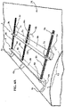
Figures 1A and1B are schematic views of a typical belted section of a corrugator machine. Acorrugator machine 50 inFigure 1A has anupper corrugator belt 52 and alower corrugator belt 54 which together support and pull acorrugated paper product 56 therethrough. After passing overhot plates 62, the upper andlower belts corrugated paper product 56 between them, maintaining the speed of the operation and cooling thepaper product 56.Weighted rollers 66 apply pressure from within the endless loops formed bybelt 52 and belt 54 toward one another, so thatcorrugated paper product 56 may be held therebetween firmly as the starch based adhesive (applied upstream from the present section) cures. Upon exit from between the upper andlower belts corrugated paper product 56 is cut and/or stacked or further processed as required.Drums 25 have lagging material (not shown) installed on their surface. -
Figure 1B shows a doublebacker section in which theupper belt 52 is replaced with a muchshorter corrugator belt 72. In this case, theupper belt 72 does not pass across thehot plates 62. Instead, theupper belt 72 is disposed opposite thelower belt 54 downstream fromhot plates 62 in what may be referred to as cooling, or pulling,zone 74. In this variety ofcorrugator machine 70, weighted steel shoes push thecorrugated paper product 56 against thehot plates 62. In this case, the upper andlower belts hot plates 62 pull thecorrugated paper product 56 through themachine 70. As before, weightedrollers 66 apply pressure from within the endless loops formed bybelt 72 and belt 54 toward one another, so thatcorrugated paper product 56 is firmly held therebetween as the starch based adhesive cures. Upon exit from betweenbelts corrugated paper product 56 is cut and/or stacked.Drums 25 have lagging material (not shown) installed on their surface. - As will be appreciated, corrugator machines place the belts, and hence the
drive drums 25 and pulleys, under highly stressful and adverse conditions. Thebelts - Conventional prior art lagging is be installed on a drum using a very strong rubber contact cement like 3M 1300L, which adheres to the lagging and to the drum surface.
- Disclosed is a lagging sufficiently elastic in the machine direction (MD) and having other properties, such that it does not require adhesives such as those above to maintain grip on a drum, and an installation apparatus therefor. For example, in one embodiment shown in
Fig. 2 , disclosed is a double coated lagging material, with a coating on both the drum surface side (inside) and the belt contact side (outside), such that the inside coating has a Coefficient of Friction to prevent the lagging, once stretched and seamed, from slipping on the drum surface. As will be understood, although the embodiment shows a double-sided lagging, as the inside coating has a Coefficient of Friction to prevent the lagging from the slipping on the drum surface, embodiments also include a lagging material with a coating on only the drum surface side (inside), and not on the paper belt side. - As will be appreciated, as the belt is wrapping a steel drum, the single or double-coated lagging prevents the lagging from slipping on the drum and also prevents (or at least minimize) the belt from slipping on the lagging. For example, a coated lagging can have a Coefficient of Friction of about 7 times greater than that of a conventional lagging, as shown in the Table 1.
Table 1 Average of Kstatic Average of Kdynamic Conventional Lagging steel 0.30 0.26 Coated Lagging steel 1.58 1.41 - For such a lagging, it is advantageous to have, among other things, an efficient and effective way to install the lagging on the drum without glue adhesive. For example, lagging is replaced on a periodic basis due to wear or for other reasons. For a conventional prior art lagging material such as that heretofore described, once it is glued to the drum surface, in order to replace it (e.g. annually) a crew of people have to grind, scrape, and remove all the material off the roll/drum to allow the new glue and lagging to be installed. In most cases, this requires several days to accomplish while the machine is down and out of operation.
- In various embodiments the lagging material is configured to be a lagging for a corrugator machine drive roll/drum in the manufacture of corrugated packaging board. There are many variations of lagging, some woven, some woven with needled batt, some coated on the belt (or non drum) surface contact side; however no conventional lagging material has a cross-machine direction (CD) seam or is made to be on machine seamable. Accordingly, in one embodiment, as shown at
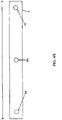
FIG. 2 , disclosed is a lagging sufficiently elastic in the machine direction and having other properties such that it does not require strong adhesives or glue to remain on the surface of thedrum 25 during operation. For example, in one embodiment, disclosed is a lagging including a double coated 19, 20substrate coating material 10, such that the Coefficient of Friction of the stretched lagging is sufficient for the lagging to remain in place on the exterior drum surface during operation of the machine and to prevent the corrugator belt from slipping on the drive drum while moving through the corrugator machine. Thecoatings outer surface 19 can be the same as that of the drum-contact surface 20, or can be different (i.e., a functional coating chosen for desired qualities for the inner/outer surfaces).Coatings - In another embodiment, shown at
FIG. 2A , a lagging includes a laggingmaterial 10 including asubstrate 18 with asingle coating 20 on only the drum surface side (inside). As will be understood,FIGS. 2A and 2B are exemplary embodiments of a double coated lagging material and single coated lagging material respectively, and the number of substrate layers, materials can vary in other embodiments. - Accordingly, specifications for a lagging material can be configured for use on industrial machines as described herein. Exemplary weights and caliper ranges for embodiments of the lagging including (1) an uncoated substrate, (2) a single coated lagging coated only on the drum contact side, or (3) double coated on the drum contact side and sheet contact side are given in Table 2 as follows.
TABLE 2 Nominal Weight Low Range (-10%) High Range (+50%) Nominal Weight Low Range (-10%) High Range (+50%) oz/ft2 oz/ft2 oz/ft2 kg/m2 kg/m2 kg/m2 Substrate 7.0 6.3 10.5 2.1 1.9 3.2 Single Coated 11.9 10.7 17.9 3.6 3.3 5.4 Double Coated 16.8 15.1 25.2 5.1 4.6 7.7 Nominal Caliper Low Range (-10%) High Range (+50%) Nominal Caliper Low Range (-10%) High Range (+50%) inches inches inches mm mm mm Substrate 0.180 0.162 0.270 4.6 4.1 6.9 Nominal Caliper Low Range (-10%) High Range (+50%) Nominal Caliper Low Range (-10%) High Range (+50%) inches inches inches mm mm mm Single Coated 0.213 0.192 0.320 5.4 4.9 8.1 Double Coated 0.245 0.221 0.368 6.2 5.6 9.3 - As will be appreciated, the higher end of the range is elevated as there may be some machines that may need a thicker belt on one of the drive rolls so that the effective diameter (e.g., diameter of the roll together with thicknesses of the lagging and the corrugator belt) of the two drive rolls are the same and they pull the corrugator board at the same speed.
- In one exemplary embodiment, a lagging
material 10 ofFIG. 2 can be a woven substrate with needledbatt fiber - A seamable lagging material can be configured to be installed for use on a cylindrical pulley or drum for an industrial machine. In another embodiment, as shown in
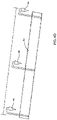
FIGS. 3A ,3B , and3C , the laggingmaterial 10 is made seamable for easy installation and removal from adrum 25.FIGS. 3A ,3B and3C are a respectively a perspective view, a top view and a side view of the laggingmaterial 10 as installed on adrum 25. The lagging material comprises a seamingarea 13 for seaming opposing ends 11, 12 of a laggingmaterial 10 when brought together. InFIGS 3A and3B , Theseam area 13 is shown as aclipper hook seam 16, however as will be appreciated, theseam 16 can include seaming methods or elements known in the art of industrial fabrics, such as clipper hook seams, spiral-links, and pin-seams wherein the yarns of the substrate actually form seaming loops themselves, or any other seaming method such that the seaming elements for each edge of the lagging can be interdigitated, forming a tunnel in which a pin orpintle 17 can be inserted therein. So too are other non-pintle or pin methods of seaming as known to those of ordinary skill in the art within the scope of disclosed embodiments, as for example, sewn or seamed webbing where seaming tabs affixed at theends seam 16, and theends seam 16 have been connected with a pin. -
FIGS. 4A and4C are respectively a perspective view and plan view of an installation device 1 for installing aseamable lagging material 10 onto a drum surface. The apparatus comprises two opposedelongate members elongate member drum 25 over opposing sides of a seamingarea 13 for aseam 16 of a laggingmaterial 10 for installation of the laggingmaterial 10 on thedrum 25. Theelongate members material 10 itself. For example, for a lagging installed on a drum/pulley of a corrugator machine, the elongate member can be about 24 inches (610 mm), which is the cross-machine direction (CD) size/dimension for such a lagging. As will be understood, corrugator machines can have drums of cross-machine direction (CD) widths of 5 meters(approximately 200 inches) or more. Thus the laggingmaterial 10 as just described could be applied in circumferential strips, and thus installed on thedrum 25 in sections until the full surface is covered. However, the installation tool can be configured to the desired cross-machine direction (CD) width for anylagging size 10, including up to a cross-machine direction (CD) width where a "full size" lagging 10 can be installed in one piece on adrum 25. - In one embodiment the each elongate member comprises a
base portion upright portion end drum 25 for installation thereon. The base of the angle iron is placed along the cross-machine direction (CD) on the drum over one joiningend 11 of the lagging 10, and theupright portion elongate member 2 is configured to be substantially laterally paired in the machine direction (MD) with an opposingelongate member 3 around theseam area 13 when installing the laggingmaterial 10 on thedrum 25. As will be understood, while the elongate member is shown as an angle iron, other embodiments are contemplated. For example, instead of an angle iron, a rod or planar element could be structured to act as an installation apparatus. - A plurality of lagging material engagement members 4, 5 can be attached to each opposed
elongate member hook elements elongate member FIG. 4A , three laggingmaterial engagement elements elongate member FIG. 4A , the hooks are attached to the bottom upper surface of thebase elongate member hook elements angle iron -
FIG 4B is a plan view showing theelongate member 2 further comprising an angle iron; and the plurality ofhook elements angle iron 2. For example, in the embodiment three 6 inch by 1/8 inch (152 mm by 3.12 mm) hooks 4a, 4b, 4c are welded to the bottom of theangle iron 2, which gives sufficient strength to withstand the tensile strain on the apparatus 1 when installing the laggingmaterial 10 onto the drum, as described herein. - As will be understood, other embodiments of engagement devices 4, 5 can be employed, such as clasps. Also, any number of techniques may be used to attach engagement devices 4, 5 such as welding, screwing, or hooking to an
elongated member - As shown in
FIGS. 4A-4D , the lagging material engagement members 4, 5 are spaced at substantially regular intervals along the cross-machine direction (CD) of each of theelongate members FIG. 4B , themiddle engagement member 4b can be somewhat off-center by a measurement sufficient to allow a tensioning member 8 to be operatively included in the installation apparatus. For example, for anelongate member 2 that is 24 inches (610 mm) in cross-machine direction (CD), the space betweenengagement member 4a andengagement member 4b can be from about 9 to about 11 inches (from about 228 mm to about 279 mm), and the space betweenengagement member 4b and engagement member 4c can be from about 15 to about 13 inches (from about 381 mm to about 330 mm). In an embodiment where eachelongate member FIG. 4C . - Each lagging material engagement member 4, 5 is positioned to engage the seaming
area 13 at corresponding openings 14, 15 on the laggingmaterial 10. For example, as shown inFIG. 4A , oneelongate member 2 has threehooks end 11 of the lagging material at correspondingopenings material 10. Thehooks material 10. The opposingelongate member 3 has threehooks end 12 of the lagging material at correspondingopenings material 10. Thehooks openings material material area 13 when the installation apparatus is employed, as discussed herein. - As shown on
FIGS. 4A and4C , each laggingmaterial engagement member elongate member 2 is substantially laterally paired in the machine direction (MD) with an opposing laggingmaterial engagement elongate member 3. As shown,hook 4a is paired in the machine direction (MD) withhook 5a,hook 4b is paired in the machine direction (MD) withhook 5b, and hook 4c is pared in the machine direction (MD) with 5c. As explained above, the hooks are positioned to engage correspondingopenings opposing opening material 10 when the lagging material is wrapped around adrum 25 for installation thereon. As shown,opening 14a is paired in the machine direction (MD) withhook 15a,opening 14b is paired in the machine direction (MD) withhook 15b, andopening 14c is paired in the machine direction (MD) with 15c. Again, as shown inFIG. 4C , a pairing in the machine direction (MD) allows for some differential, as for example betweenengagement members - The apparatus comprises a tensioning member 8 operably engaged with the opposed
elongate members elongate members tensioning members FIGS. 4A and4C , the tensioning device 8 can be an all-screw or threaded bolt.FIG. 4D shows a side view of the oneelongate member 2. - In another embodiment, tensioning member 8 can be acome-along winch (not shown). The come-along can operably engaged with the opposed
elongate members elongate members - As shown, the
elongate member 2 is a one quarter inch (6.4 mm) angle iron, the side view showing theupright portion 2b of the angle iron.Holes holes 6b and fromhole 6b to hole 6c are about the same, andhole 6b is in the center of theupright portion 2b. - When opposing
elongate members FIGS. 4A and4C , the inner faces of theupright portions base portions tensioning members holes corresponding holes elongate members FIGS. 4A and4C , the tensioning member 8 is a screw with a bolt end against one outside surface of oneupright portion 2b of theelongate member 2 and a nut 9 on the outside surface of theupright portion 3b of the opposingelongate member 2. As shown inFIG. 4C ,middle holes upright portions elongate members holes engagement members elongated members engagement members tensioning members material engagement members engagement members elongated members - In an embodiment where the tensioning member 8 is a come-along winch (not shown), the come-along can operably engaged with the opposed
elongate members elongate members elongate members FIGS. 4A and4C , the inner faces of theupright portions base portions holes 6a and 7a such that the winch can be operated to pull the opposingelongate members holes - Each lagging material engagement member is structured to engage a seaming
area 13 of the lagging material such that when the elongate members are drawn together, the lagging material is stretched into a seamable position to be installed on the drum. - Accordingly, a seamable lagging material can be configured to be installed for use on a cylindrical pulley or drum for an industrial machine using an installation apparatus. In another embodiment the lagging
material 10 as shown inFIGS. 3A and3B is configured to be installed using embodiments of the installation apparatus 1 as described inFIGS 4A-4D .FIGS. 3B and3C are respectively a perspective view and a top view of the laggingmaterial 10 as installed on thedrum 25. The lagging material comprises a seamingarea 13 for seaming opposing ends 11, 12 of a laggingmaterial 10 when brought together. In the embodiment shown, the openings are placed on either side of theseam area 13 in the lagging material. The laggingmaterial 10 includes a plurality of openings 14, 15 spaced along the cross-machine direction (CD) of the seamingarea 13 on each of the opposing ends 11, 12 of the lagging material, the openings configured to receive engagement members 4, 5 of an installation apparatus 1 when the laggingmaterial 10 is placed around the drum. As explained above,engagement members material engagement engagement members openings material 10. Eachopening openings material 10 when the lagging material is wrapped around adrum 25 for installation thereon. As can be seen in FIG. 5C, theopenings - A method for installing a lagging material using the device embodiments described herein is disclosed. Consistent with the embodiments of the installation apparatus 1 described in
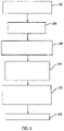
FIGS 4A-4D , disclosed is a method comprising positioning opposing ends 11, 12 of a laggingmaterial 10 around adrum 25 into for seaming. As shown inFIG. 5 , atblock 100 is shown attaching an installation apparatus 1 to a plurality of openings 14, 15 on each opposingend unstretched lagging material 10 is placed around thedrum 25 circumference bringing theends seam area 13 by engaging the seaming apparatus components to stretch the lagging material in the machine direction (MD) with the installation apparatus 1; and completing the seam of the laggingmaterial 10 onto thedrum 25. The installation of the laggingmaterial 10 on thedrum 25 stretches the laggingmaterial 10 onto the drum, and the lagging material surface in contact with the drum surface with a sufficient Coefficient of Friction such that no adhesive is required to keep the lagging from slipping on the drum surface. - At
block 200, the method comprises positioning at least two opposedelongate members drum 25 over the opposingsides area 13 of the laggingmaterial 10 and attaching a plurality of lagging material engagement members 4, 5 attached to each opposedelongate members area 13 on each of the opposing ends 11, 12 of the lagging material. At least three of the lagging material engagement devices correspond to at least three of the spaced openings at each of the opposing ends 11, 12 of the laggingmaterial 10. As described above the lagging material engagement members can further comprise hook elements, and the method includes engaging each hook at a corresponding opening on the lagging material. The lagging material engagement members are spaced at substantially regular intervals along the cross-machine direction (CD), as described herein. - Consistent with the description of the installation device 1 herein, the method further comprises engaging each lagging material engagement member 4 on one
elongate member 2 with the openings 14 on oneend 11 of the laggingmaterial 10, and engaging each lagging material engagement member 5 on the opposingelongate member 3 with the openings 15 laterally positioned in the machine direction (MD) on the opposingend 12 of the laggingmaterial 10. - At blocks 300-320, the method comprises bringing the
ends elongate members elongate members material engagement member area 13 of the laggingmaterial 10 such that when theelongate members tensioning members tensioning devices 8a...n, in the embodiment where the tensioning device is three threaded bolts or screws, an operator or operating mechanism could tighten the nuts 9a, 9b, 9c, on each of the screws such that theelongate members material 10 together into a seaming position. - In an embodiment where the tensioning member 8 is a come-along winch (not shown), the come-along winch 8 can be positioned such that a pair of hooks from the winch engages transversely through the
holes elongate members block 300 first engages the come-along winch to bring the ends of the lagging material into the seaming position, which may be sufficient to bring thewhole seam 16 into the seaming position, in which case the method moves directly to seaming at 400. Or, as another alternative, the winch can be similarly engaged in turns atholes location 6a, 7a; 6b, 7b; 6c,7c such that theelongate members material 10 together into a seaming position. - At
block 400, once all three screws have been tightened or the tensioning member otherwise operated such that theseam 16 is in the seaming position, the laggingmaterial 10 can be seamed on thedrum 25 as for example, with a pin or pintle.
Claims (18)
- An on machine seamable lagging material (10) for use on a cylindrical pulley or drum (25) for an industrial machine, the lagging material (10) comprisinga substrate (18); anda seaming element along the cross-machine direction (CD) of each of the opposing ends of the lagging material for forming a seam (16) for seaming opposing ends of the lagging material when brought together,wherein the lagging material (10) comprises a coating (20) on the drum contact inner surface of the substrate and wherein the lagging material comprises a plurality of openings spaced along the cross-machine direction (CD) of a seaming area on each of the opposing ends of the lagging material, the openings being configured to receive engagement members of an installation apparatus when the lagging material is placed around a drum/roll circumference and whereinsaid seaming element comprises clipper hooks, spiral-links, pins for pin-seams with yarns of the substrate forming seaming loops, pins or pintles for insertion in tunnels formed by_interdigitated edges of the lagging material, or seaming tabs affixed at the ends of the lagging material joined with glue or studs in the through direction to seam the fabric.
- The lagging material of claim 1, wherein the lagging material comprises:
each opening being substantially laterally paired in the machine direction (MD) with an opposing opening on the opposing end of the lagging material. - The lagging material of claim 1, comprising:
a first coating on a drum-contact inner surface of the substrate; and wherein the drum contact surface coating increases the Coefficient of Friction of the lagging material when the lagging material is installed onto the drum such that no additional adhesive is required. - The lagging material of claim 1, wherein the coating comprises an elastomeric coating made from a thermoplastic or thermoset material.
- The lagging material of claim 4, wherein the coating includes an elastomer selected from the group of a polyurethane, a rubber, silicone, and other known elastomeric materials.
- The lagging material of claim 1 comprising:
a second coating on the belt contact surface of the substrate. - The lagging material of claim 6,
wherein the average static Coefficient of Friction when static is Ks = 2.81 and the average dynamic Coefficient of Friction (CoF) is Kd = 2.44 for the coated belt and the paper board the coated belt is pulling or wherein the average static Coefficient of Friction (CoF) is about Ks = 1.58 and the average dynamic Coefficient of Friction is about Kd = 1.41 for a steel drum. - The lagging material of claim 1, wherein the first and second coatings are the same material or wherein the first and second coatings are different materials.
- The lagging material of claim 1, wherein the substrate comprises at least one layer selected from the group of woven or non-woven fibers and/or yarns or spiral links.
- The lagging material of claim 4, wherein the lagging material substrate comprises fibers and/or yarns selected from the group of: natural fibers and/or yarns and synthetic fibers and/or yarns.
- The lagging material of claim 9, wherein the substrate comprises: at least two layers.
- The lagging material of claim 11, wherein the substrate comprises:a woven substrate layer;and at least one fiberous batt material layer.
- The lagging material of claim 1, wherein the lagging material without a coating includes a weight of from about 6.3 oz/ft2 (1.9 kg/m2) to about 10.5 oz/ft2 (3.2 kg/m2) and a caliper (thickness) of from about 0.162 inches (4.1 mm) to about 0.270 inches (6.9 mm), orwherein the lagging material without a coating includes a weight of approximately 7 oz/ft2 (2.1 kg/m2) and a caliper (thickness) of approximately 0.180 inches (4.6 mm),or wherein the coated lagging material has only the first coating on the drum contact side, and comprises a weight of from about 10.7 oz/ft2 (3.3 kg/m2) to about 17.9 oz/ft2 (5.4 kg/m2) and a caliper (thickness) of from about 0.192 inches (4.9 mm) to about 0.320 inches (8.1 mm),or wherein the coated lagging material includes a coated weight of about 11.9 oz/ft2 (3.6 kg/m2) and a caliper of about 0.213 inches (5.4 mm),or wherein the coated lagging material comprises a weight of from about 15.1 oz/ft2 (4.6 kg/m2) to about 25.2 oz/ft2 (7.7 kg/m2) and a caliper (thickness) of from about 0.221 inches (5.6 mm) to about 0.368 inches (9.3 mm),or wherein the coated lagging material includes a coated weight of about 16.8 oz/ft2 (5.1 kg/m2) and a caliper of about 0.245 inches (6.2 mm).
- A method to install an on machine seamable coated lagging material comprising:positioning opposing ends of a coated lagging material around a drum (25) for seaming, the coated lagging material having a first coating (20) on the drum contact side;attaching an installation device to a plurality of openings (14, 15) on each opposing end of the coated lagging material (10), the openings configured to receive engagement members (4, 5) of the installation apparatus when the coated lagging material is placed around a drum;bringing the ends of the coated lagging material (10) into a seaming position with the installation apparatus; andseaming the coated lagging material (10) onto the drum (25),whereby the installation of the coated lagging material on the drum stretches the coated lagging material (10) onto the drum and the coated lagging material has a Coefficient of Friction such that no additional adhesive is required,wherein a seaming element comprises clipper hooks, spiral-links, pins for pin-seams with yarns of the substrate forming seaming loops, pins or pintles for insertion in tunnels formed by interdigitated edges of the lagging material, or seaming tabs affixed at the ends of the lagging material joined with glue or studs in the through direction to seam the fabric.
- The method of claim 14, further comprising:positioning at least two opposed elongate members longitudinally along the cross-machine direction (CD) of a drum over the opposing sides of a seaming area of the coated lagging material;attaching a plurality of coated lagging material engagement members or at least three of the coated lagging material engagement devices attached to each opposed elongate members along the cross-machine direction (CD) to the plurality of openings or to at least three of the correspondingly spaced openings, the openings being correspondingly spaced along the cross-machine direction (CD) of the seaming area on each of the opposing ends of the coated lagging material; andbringing the ends of the coated lagging material together by operating a tensioning member operably engaged with the opposed elongate members for drawing the opposed elongate members together in the machine direction;wherein each coated lagging material engagement member is structured to engage a seaming area of the coated lagging material such that when the elongate members are drawn together, the coated lagging material is stretched into a seamable position to be installed on the drum.
- The method of claim 14, the method further comprising: operating a plurality of tensioning members positioned proximate to the engagement members.
- The method of claim 14, the method further comprising: engaging engagement members with the openings on one end of the coated lagging material, and engaging other engagement members with the openings laterally positioned in machine direction (MD) on the opposing end of the coated lagging material.
- The method of claim 14, the method further comprising:positioning the tensioning member between each of the engagement members such that the tensioning member can operably engage the engagement members;engaging the tensioning member with at least one opening on each engagement member; andoperating the tensioning member.
Priority Applications (3)
| Application Number | Priority Date | Filing Date | Title |
|---|---|---|---|
| EP14194226.8A EP2846063B1 (en) | 2011-09-23 | 2012-09-24 | Installation apparatus for a drum lagging material |
| PL14194226T PL2846063T3 (en) | 2011-09-23 | 2012-09-24 | Installation apparatus for a drum lagging material |
| PL12778511T PL2758692T3 (en) | 2011-09-23 | 2012-09-24 | Drum lagging material and installation method therefor |
Applications Claiming Priority (3)
| Application Number | Priority Date | Filing Date | Title |
|---|---|---|---|
| US201161538470P | 2011-09-23 | 2011-09-23 | |
| US201161542657P | 2011-10-03 | 2011-10-03 | |
| PCT/US2012/056904 WO2013044227A2 (en) | 2011-09-23 | 2012-09-24 | Drum lagging material and installation apparatus therefor |
Related Child Applications (2)
| Application Number | Title | Priority Date | Filing Date |
|---|---|---|---|
| EP14194226.8A Division-Into EP2846063B1 (en) | 2011-09-23 | 2012-09-24 | Installation apparatus for a drum lagging material |
| EP14194226.8A Division EP2846063B1 (en) | 2011-09-23 | 2012-09-24 | Installation apparatus for a drum lagging material |
Publications (3)
| Publication Number | Publication Date |
|---|---|
| EP2758692A2 EP2758692A2 (en) | 2014-07-30 |
| EP2758692B1 EP2758692B1 (en) | 2019-11-13 |
| EP2758692B2 true EP2758692B2 (en) | 2022-07-27 |
Family
ID=47076383
Family Applications (2)
| Application Number | Title | Priority Date | Filing Date |
|---|---|---|---|
| EP12778511.1A Active EP2758692B2 (en) | 2011-09-23 | 2012-09-24 | Drum lagging material and installation method therefor |
| EP14194226.8A Active EP2846063B1 (en) | 2011-09-23 | 2012-09-24 | Installation apparatus for a drum lagging material |
Family Applications After (1)
| Application Number | Title | Priority Date | Filing Date |
|---|---|---|---|
| EP14194226.8A Active EP2846063B1 (en) | 2011-09-23 | 2012-09-24 | Installation apparatus for a drum lagging material |
Country Status (12)
| Country | Link |
|---|---|
| US (1) | US20130079206A1 (en) |
| EP (2) | EP2758692B2 (en) |
| JP (2) | JP6195564B2 (en) |
| KR (2) | KR102075022B1 (en) |
| CN (2) | CN105402313B (en) |
| BR (1) | BR112014006906B1 (en) |
| CA (2) | CA2849451C (en) |
| ES (2) | ES2758399T5 (en) |
| MX (2) | MX2014003470A (en) |
| PL (2) | PL2758692T3 (en) |
| TW (2) | TWI596003B (en) |
| WO (1) | WO2013044227A2 (en) |
Families Citing this family (4)
| Publication number | Priority date | Publication date | Assignee | Title |
|---|---|---|---|---|
| ES2758399T5 (en) | 2011-09-23 | 2022-11-14 | Albany Int Corp | Drum lining material and installation method thereof |
| DE102015118157A1 (en) * | 2015-10-23 | 2017-04-27 | Trützschler GmbH & Co Kommanditgesellschaft | Device for the thermal treatment of a textile web |
| FR3046997B1 (en) * | 2016-01-27 | 2019-07-12 | Bricq | DEVICE COMPRISING A DRIVING CYLINDER AND A SELF-ENCAPSING COATING, METHOD AND MACHINE THEREFOR |
| JP6712890B2 (en) * | 2016-03-31 | 2020-06-24 | 特種東海製紙株式会社 | Paper that can be stably fed |
Family Cites Families (37)
| Publication number | Priority date | Publication date | Assignee | Title |
|---|---|---|---|---|
| US1659883A (en) * | 1926-03-27 | 1928-02-21 | Lorentz John | Belt fastener |
| GB470261A (en) * | 1936-02-11 | 1937-08-11 | Fritz Max Schwabe | Improvements in or relating to belt or conveyor pulleys or rollers, friction clutches, brake drums and the like |
| US2595453A (en) * | 1949-04-09 | 1952-05-06 | John L Gilmore | Stand and dolly for trailer tongues |
| US2959453A (en) * | 1956-04-27 | 1960-11-08 | Harvey C Jacobs | Drill pipe protector |
| US3051532A (en) * | 1958-11-20 | 1962-08-28 | Charles H Collett | Well pipe protector |
| US3300181A (en) * | 1965-08-19 | 1967-01-24 | Kinkead Industries | Carpet tool for drawing seam edges to-gether by single throw lever means |
| US3972105A (en) * | 1975-03-03 | 1976-08-03 | Mount Vernon Dryer Felt Co. | Seam gripping device |
| DE2623437A1 (en) | 1976-05-25 | 1977-12-08 | Jwi Ltd | Closure of wide, heavy fabric seams - using pintle through intermeshed arrays of attached loops |
| CH622595A5 (en) * | 1977-06-10 | 1981-04-15 | Semperit Ag | Facing on a driving drum |
| JPS6026020B2 (en) * | 1979-06-20 | 1985-06-21 | 呉羽センイ株式会社 | Heat resistant lagging sheet |
| JPS603712U (en) * | 1983-06-22 | 1985-01-11 | 東海ゴム工業株式会社 | resin conveyor belt |
| FR2628453B1 (en) * | 1988-03-08 | 1990-11-16 | Cofpa | METHOD OF LAYING A FABRIC AROUND A CYLINDER AND PRE-TENSIONING DEVICE FOR IMPLEMENTING THE METHOD |
| US5015220A (en) * | 1988-08-03 | 1991-05-14 | Tamfelt, Inc. | Seam for work fabric and method of manufacture thereof |
| JP3129559B2 (en) * | 1993-01-19 | 2001-01-31 | 東洋紡績株式会社 | Heat resistant lagging sheet |
| US5611374A (en) * | 1993-03-30 | 1997-03-18 | Hutchinson | Thermally insulating pipe lagging and method of manufacture |
| US6276420B1 (en) | 1998-04-17 | 2001-08-21 | Albany International Corp. | Coated corrugator belt |
| JP2001171024A (en) * | 1999-10-06 | 2001-06-26 | Mitsubishi Heavy Ind Ltd | Apparatus and method for manufacturing single-faced corrugated cardboard |
| JP4679708B2 (en) * | 2000-10-19 | 2011-04-27 | シキボウ株式会社 | Corrugator belt fitting |
| US6491794B2 (en) * | 2001-03-29 | 2002-12-10 | Albany International Corp. | Base structure for seamed papermaker's fabrics |
| US6627045B2 (en) * | 2001-10-09 | 2003-09-30 | Albany International Corp. | Seam for a corrugator belt |
| DE10229539B4 (en) * | 2002-07-01 | 2005-09-01 | Telair International Gmbh | Roller drive unit |
| JP2004338868A (en) * | 2003-05-15 | 2004-12-02 | San-Ai Industries Inc | Belt connection method and belt connection device in belt conveyor device for conveying article |
| US8840683B2 (en) * | 2003-11-19 | 2014-09-23 | Albany International Corp. | Industrial textile fabric |
| US7140487B2 (en) * | 2005-01-12 | 2006-11-28 | San-Ai Industries, Inc. | Conveyor belt and a method of making same |
| US7260924B2 (en) | 2005-01-25 | 2007-08-28 | Voith Fabrics, Inc. | Seam pintle for paper making fabric |
| EP1812729B1 (en) | 2005-09-01 | 2011-08-10 | Wilhelm Sülzle E.K. | Band or belt end provided at its end with a wire-hook connector |
| CN2878283Y (en) * | 2005-12-29 | 2007-03-14 | 福建南方路面机械有限公司 | Replacement encapsulated drum |
| DK2055831T3 (en) | 2007-10-30 | 2011-09-12 | Muehlen Sohn Gmbh & Co | Textile belt with thickness-reduced ends |
| JP5190255B2 (en) * | 2007-12-25 | 2013-04-24 | 中興化成工業株式会社 | Resin-coated wire mesh belt for corrugated paper manufacture |
| DE102008002301A1 (en) | 2008-06-09 | 2009-12-10 | Voith Patent Gmbh | Continuous belt e.g. tension belt, for e.g. paper machine, has upper and lower connection sections lying parallel to one another so that thread sections are bent to straps and are attached to connecting element to form connection zone |
| US10822471B2 (en) * | 2009-02-24 | 2020-11-03 | Bando Chemical Industries, Ltd. | Friction drive belt |
| CN201373063Y (en) * | 2009-04-07 | 2009-12-30 | 平煤建工集团有限公司 | Conveyor sellotape drawing device |
| CN201507613U (en) * | 2009-09-23 | 2010-06-16 | 新兴铸管股份有限公司 | Auxiliary tension apparatus for connecting conveying belt |
| JP4616408B1 (en) * | 2010-02-19 | 2011-01-19 | イチカワ株式会社 | Process belt for papermaking |
| JP5437124B2 (en) * | 2010-03-18 | 2014-03-12 | 株式会社ニューフレアテクノロジー | Charged particle beam drawing method and charged particle beam drawing apparatus |
| CN201730958U (en) * | 2010-08-17 | 2011-02-02 | 泉州市三隆重工实业有限公司 | Novel rotary drum |
| ES2758399T5 (en) | 2011-09-23 | 2022-11-14 | Albany Int Corp | Drum lining material and installation method thereof |
-
2012
- 2012-09-24 ES ES12778511T patent/ES2758399T5/en active Active
- 2012-09-24 EP EP12778511.1A patent/EP2758692B2/en active Active
- 2012-09-24 TW TW101134913A patent/TWI596003B/en active
- 2012-09-24 US US13/625,533 patent/US20130079206A1/en active Pending
- 2012-09-24 MX MX2014003470A patent/MX2014003470A/en active IP Right Grant
- 2012-09-24 KR KR1020197000978A patent/KR102075022B1/en active IP Right Grant
- 2012-09-24 CN CN201510791956.2A patent/CN105402313B/en active Active
- 2012-09-24 ES ES14194226T patent/ES2734004T3/en active Active
- 2012-09-24 WO PCT/US2012/056904 patent/WO2013044227A2/en active Application Filing
- 2012-09-24 BR BR112014006906-9A patent/BR112014006906B1/en active IP Right Grant
- 2012-09-24 EP EP14194226.8A patent/EP2846063B1/en active Active
- 2012-09-24 CA CA2849451A patent/CA2849451C/en active Active
- 2012-09-24 JP JP2014532072A patent/JP6195564B2/en active Active
- 2012-09-24 KR KR1020147010837A patent/KR101997871B1/en active IP Right Grant
- 2012-09-24 PL PL12778511T patent/PL2758692T3/en unknown
- 2012-09-24 CA CA3027222A patent/CA3027222C/en active Active
- 2012-09-24 TW TW106108559A patent/TWI617435B/en active
- 2012-09-24 CN CN201280056778.3A patent/CN103987991B/en active Active
- 2012-09-24 PL PL14194226T patent/PL2846063T3/en unknown
-
2014
- 2014-03-21 MX MX2020001710A patent/MX2020001710A/en unknown
-
2017
- 2017-04-11 JP JP2017078499A patent/JP6449932B2/en active Active
Also Published As
Similar Documents
| Publication | Publication Date | Title |
|---|---|---|
| EP2758692B2 (en) | Drum lagging material and installation method therefor | |
| RU2530371C2 (en) | Industrial cloth including helical coiled material strips | |
| RU2638516C2 (en) | Technical fabric and welding method of seam area, using ultrasonic welding | |
| TWI653405B (en) | Industrial fabric and forming method thereof | |
| RU2653030C2 (en) | Method for producing endless belt | |
| EP2354299A1 (en) | Industrial fabric with wear resistant coating | |
| US6155319A (en) | Unit for joining paper sheets together in corrugated board manufacturing equipment | |
| US20030069120A1 (en) | Continuous in-line pleating apparatus and process | |
| EP2339065A1 (en) | Industrial fabric with traction coating | |
| EP1340004B1 (en) | Power transmission belt | |
| US20190009492A1 (en) | Device having a feed roll and a self-adhesive fastener, and associated method and machine |
Legal Events
| Date | Code | Title | Description |
|---|---|---|---|
| PUAI | Public reference made under article 153(3) epc to a published international application that has entered the european phase |
Free format text: ORIGINAL CODE: 0009012 |
|
| 17P | Request for examination filed |
Effective date: 20140331 |
|
| AK | Designated contracting states |
Kind code of ref document: A2 Designated state(s): AL AT BE BG CH CY CZ DE DK EE ES FI FR GB GR HR HU IE IS IT LI LT LU LV MC MK MT NL NO PL PT RO RS SE SI SK SM TR |
|
| DAX | Request for extension of the european patent (deleted) | ||
| 17Q | First examination report despatched |
Effective date: 20160602 |
|
| STAA | Information on the status of an ep patent application or granted ep patent |
Free format text: STATUS: EXAMINATION IS IN PROGRESS |
|
| GRAP | Despatch of communication of intention to grant a patent |
Free format text: ORIGINAL CODE: EPIDOSNIGR1 |
|
| STAA | Information on the status of an ep patent application or granted ep patent |
Free format text: STATUS: GRANT OF PATENT IS INTENDED |
|
| INTG | Intention to grant announced |
Effective date: 20181203 |
|
| GRAJ | Information related to disapproval of communication of intention to grant by the applicant or resumption of examination proceedings by the epo deleted |
Free format text: ORIGINAL CODE: EPIDOSDIGR1 |
|
| STAA | Information on the status of an ep patent application or granted ep patent |
Free format text: STATUS: EXAMINATION IS IN PROGRESS |
|
| GRAP | Despatch of communication of intention to grant a patent |
Free format text: ORIGINAL CODE: EPIDOSNIGR1 |
|
| STAA | Information on the status of an ep patent application or granted ep patent |
Free format text: STATUS: GRANT OF PATENT IS INTENDED |
|
| INTC | Intention to grant announced (deleted) | ||
| INTG | Intention to grant announced |
Effective date: 20190516 |
|
| GRAS | Grant fee paid |
Free format text: ORIGINAL CODE: EPIDOSNIGR3 |
|
| GRAA | (expected) grant |
Free format text: ORIGINAL CODE: 0009210 |
|
| STAA | Information on the status of an ep patent application or granted ep patent |
Free format text: STATUS: THE PATENT HAS BEEN GRANTED |
|
| AK | Designated contracting states |
Kind code of ref document: B1 Designated state(s): AL AT BE BG CH CY CZ DE DK EE ES FI FR GB GR HR HU IE IS IT LI LT LU LV MC MK MT NL NO PL PT RO RS SE SI SK SM TR |
|
| REG | Reference to a national code |
Ref country code: CH Ref legal event code: EP Ref country code: AT Ref legal event code: REF Ref document number: 1201991 Country of ref document: AT Kind code of ref document: T Effective date: 20191115 |
|
| REG | Reference to a national code |
Ref country code: DE Ref legal event code: R096 Ref document number: 602012065675 Country of ref document: DE |
|
| REG | Reference to a national code |
Ref country code: IE Ref legal event code: FG4D |
|
| REG | Reference to a national code |
Ref country code: SE Ref legal event code: TRGR |
|
| REG | Reference to a national code |
Ref country code: DE Ref legal event code: R026 Ref document number: 602012065675 Country of ref document: DE |
|
| PLBI | Opposition filed |
Free format text: ORIGINAL CODE: 0009260 |
|
| REG | Reference to a national code |
Ref country code: NL Ref legal event code: MP Effective date: 20191113 |
|
| REG | Reference to a national code |
Ref country code: LT Ref legal event code: MG4D |
|
| REG | Reference to a national code |
Ref country code: FI Ref legal event code: MDE Opponent name: MA HLEN SOHN GMBH & CO. KG |
|
| 26 | Opposition filed |
Opponent name: MUEHLEN SOHN GMBH & CO. KG Effective date: 20200309 |
|
| PG25 | Lapsed in a contracting state [announced via postgrant information from national office to epo] |
Ref country code: NO Free format text: LAPSE BECAUSE OF FAILURE TO SUBMIT A TRANSLATION OF THE DESCRIPTION OR TO PAY THE FEE WITHIN THE PRESCRIBED TIME-LIMIT Effective date: 20200213 Ref country code: GR Free format text: LAPSE BECAUSE OF FAILURE TO SUBMIT A TRANSLATION OF THE DESCRIPTION OR TO PAY THE FEE WITHIN THE PRESCRIBED TIME-LIMIT Effective date: 20200214 Ref country code: BG Free format text: LAPSE BECAUSE OF FAILURE TO SUBMIT A TRANSLATION OF THE DESCRIPTION OR TO PAY THE FEE WITHIN THE PRESCRIBED TIME-LIMIT Effective date: 20200213 Ref country code: LT Free format text: LAPSE BECAUSE OF FAILURE TO SUBMIT A TRANSLATION OF THE DESCRIPTION OR TO PAY THE FEE WITHIN THE PRESCRIBED TIME-LIMIT Effective date: 20191113 Ref country code: LV Free format text: LAPSE BECAUSE OF FAILURE TO SUBMIT A TRANSLATION OF THE DESCRIPTION OR TO PAY THE FEE WITHIN THE PRESCRIBED TIME-LIMIT Effective date: 20191113 Ref country code: PT Free format text: LAPSE BECAUSE OF FAILURE TO SUBMIT A TRANSLATION OF THE DESCRIPTION OR TO PAY THE FEE WITHIN THE PRESCRIBED TIME-LIMIT Effective date: 20200313 Ref country code: NL Free format text: LAPSE BECAUSE OF FAILURE TO SUBMIT A TRANSLATION OF THE DESCRIPTION OR TO PAY THE FEE WITHIN THE PRESCRIBED TIME-LIMIT Effective date: 20191113 |
|
| REG | Reference to a national code |
Ref country code: ES Ref legal event code: FG2A Ref document number: 2758399 Country of ref document: ES Kind code of ref document: T3 Effective date: 20200505 |
|
| PG25 | Lapsed in a contracting state [announced via postgrant information from national office to epo] |
Ref country code: IS Free format text: LAPSE BECAUSE OF FAILURE TO SUBMIT A TRANSLATION OF THE DESCRIPTION OR TO PAY THE FEE WITHIN THE PRESCRIBED TIME-LIMIT Effective date: 20200313 Ref country code: HR Free format text: LAPSE BECAUSE OF FAILURE TO SUBMIT A TRANSLATION OF THE DESCRIPTION OR TO PAY THE FEE WITHIN THE PRESCRIBED TIME-LIMIT Effective date: 20191113 Ref country code: RS Free format text: LAPSE BECAUSE OF FAILURE TO SUBMIT A TRANSLATION OF THE DESCRIPTION OR TO PAY THE FEE WITHIN THE PRESCRIBED TIME-LIMIT Effective date: 20191113 |
|
| PG25 | Lapsed in a contracting state [announced via postgrant information from national office to epo] |
Ref country code: AL Free format text: LAPSE BECAUSE OF FAILURE TO SUBMIT A TRANSLATION OF THE DESCRIPTION OR TO PAY THE FEE WITHIN THE PRESCRIBED TIME-LIMIT Effective date: 20191113 |
|
| PG25 | Lapsed in a contracting state [announced via postgrant information from national office to epo] |
Ref country code: CZ Free format text: LAPSE BECAUSE OF FAILURE TO SUBMIT A TRANSLATION OF THE DESCRIPTION OR TO PAY THE FEE WITHIN THE PRESCRIBED TIME-LIMIT Effective date: 20191113 Ref country code: DK Free format text: LAPSE BECAUSE OF FAILURE TO SUBMIT A TRANSLATION OF THE DESCRIPTION OR TO PAY THE FEE WITHIN THE PRESCRIBED TIME-LIMIT Effective date: 20191113 Ref country code: RO Free format text: LAPSE BECAUSE OF FAILURE TO SUBMIT A TRANSLATION OF THE DESCRIPTION OR TO PAY THE FEE WITHIN THE PRESCRIBED TIME-LIMIT Effective date: 20191113 Ref country code: EE Free format text: LAPSE BECAUSE OF FAILURE TO SUBMIT A TRANSLATION OF THE DESCRIPTION OR TO PAY THE FEE WITHIN THE PRESCRIBED TIME-LIMIT Effective date: 20191113 |
|
| REG | Reference to a national code |
Ref country code: AT Ref legal event code: MK05 Ref document number: 1201991 Country of ref document: AT Kind code of ref document: T Effective date: 20191113 |
|
| PLAX | Notice of opposition and request to file observation + time limit sent |
Free format text: ORIGINAL CODE: EPIDOSNOBS2 |
|
| PG25 | Lapsed in a contracting state [announced via postgrant information from national office to epo] |
Ref country code: SM Free format text: LAPSE BECAUSE OF FAILURE TO SUBMIT A TRANSLATION OF THE DESCRIPTION OR TO PAY THE FEE WITHIN THE PRESCRIBED TIME-LIMIT Effective date: 20191113 Ref country code: SK Free format text: LAPSE BECAUSE OF FAILURE TO SUBMIT A TRANSLATION OF THE DESCRIPTION OR TO PAY THE FEE WITHIN THE PRESCRIBED TIME-LIMIT Effective date: 20191113 |
|
| PG25 | Lapsed in a contracting state [announced via postgrant information from national office to epo] |
Ref country code: AT Free format text: LAPSE BECAUSE OF FAILURE TO SUBMIT A TRANSLATION OF THE DESCRIPTION OR TO PAY THE FEE WITHIN THE PRESCRIBED TIME-LIMIT Effective date: 20191113 Ref country code: SI Free format text: LAPSE BECAUSE OF FAILURE TO SUBMIT A TRANSLATION OF THE DESCRIPTION OR TO PAY THE FEE WITHIN THE PRESCRIBED TIME-LIMIT Effective date: 20191113 |
|
| PLBB | Reply of patent proprietor to notice(s) of opposition received |
Free format text: ORIGINAL CODE: EPIDOSNOBS3 |
|
| PLBP | Opposition withdrawn |
Free format text: ORIGINAL CODE: 0009264 |
|
| PLAY | Examination report in opposition despatched + time limit |
Free format text: ORIGINAL CODE: EPIDOSNORE2 |
|
| PG25 | Lapsed in a contracting state [announced via postgrant information from national office to epo] |
Ref country code: MC Free format text: LAPSE BECAUSE OF FAILURE TO SUBMIT A TRANSLATION OF THE DESCRIPTION OR TO PAY THE FEE WITHIN THE PRESCRIBED TIME-LIMIT Effective date: 20191113 |
|
| REG | Reference to a national code |
Ref country code: CH Ref legal event code: PL |
|
| PG25 | Lapsed in a contracting state [announced via postgrant information from national office to epo] |
Ref country code: LU Free format text: LAPSE BECAUSE OF NON-PAYMENT OF DUE FEES Effective date: 20200924 |
|
| PLBC | Reply to examination report in opposition received |
Free format text: ORIGINAL CODE: EPIDOSNORE3 |
|
| PG25 | Lapsed in a contracting state [announced via postgrant information from national office to epo] |
Ref country code: LI Free format text: LAPSE BECAUSE OF NON-PAYMENT OF DUE FEES Effective date: 20200930 Ref country code: IE Free format text: LAPSE BECAUSE OF NON-PAYMENT OF DUE FEES Effective date: 20200924 Ref country code: CH Free format text: LAPSE BECAUSE OF NON-PAYMENT OF DUE FEES Effective date: 20200930 |
|
| PGFP | Annual fee paid to national office [announced via postgrant information from national office to epo] |
Ref country code: PL Payment date: 20210831 Year of fee payment: 10 |
|
| PG25 | Lapsed in a contracting state [announced via postgrant information from national office to epo] |
Ref country code: TR Free format text: LAPSE BECAUSE OF FAILURE TO SUBMIT A TRANSLATION OF THE DESCRIPTION OR TO PAY THE FEE WITHIN THE PRESCRIBED TIME-LIMIT Effective date: 20191113 Ref country code: MT Free format text: LAPSE BECAUSE OF FAILURE TO SUBMIT A TRANSLATION OF THE DESCRIPTION OR TO PAY THE FEE WITHIN THE PRESCRIBED TIME-LIMIT Effective date: 20191113 Ref country code: CY Free format text: LAPSE BECAUSE OF FAILURE TO SUBMIT A TRANSLATION OF THE DESCRIPTION OR TO PAY THE FEE WITHIN THE PRESCRIBED TIME-LIMIT Effective date: 20191113 |
|
| PUAH | Patent maintained in amended form |
Free format text: ORIGINAL CODE: 0009272 |
|
| STAA | Information on the status of an ep patent application or granted ep patent |
Free format text: STATUS: PATENT MAINTAINED AS AMENDED |
|
| PG25 | Lapsed in a contracting state [announced via postgrant information from national office to epo] |
Ref country code: MK Free format text: LAPSE BECAUSE OF FAILURE TO SUBMIT A TRANSLATION OF THE DESCRIPTION OR TO PAY THE FEE WITHIN THE PRESCRIBED TIME-LIMIT Effective date: 20191113 |
|
| 27A | Patent maintained in amended form |
Effective date: 20220727 |
|
| AK | Designated contracting states |
Kind code of ref document: B2 Designated state(s): AL AT BE BG CH CY CZ DE DK EE ES FI FR GB GR HR HU IE IS IT LI LT LU LV MC MK MT NL NO PL PT RO RS SE SI SK SM TR |
|
| REG | Reference to a national code |
Ref country code: DE Ref legal event code: R102 Ref document number: 602012065675 Country of ref document: DE |
|
| REG | Reference to a national code |
Ref country code: SE Ref legal event code: RPEO |
|
| REG | Reference to a national code |
Ref country code: ES Ref legal event code: DC2A Ref document number: 2758399 Country of ref document: ES Kind code of ref document: T5 Effective date: 20221114 |
|
| PGFP | Annual fee paid to national office [announced via postgrant information from national office to epo] |
Ref country code: BE Payment date: 20220927 Year of fee payment: 11 |
|
| P01 | Opt-out of the competence of the unified patent court (upc) registered |
Effective date: 20230516 |
|
| PGFP | Annual fee paid to national office [announced via postgrant information from national office to epo] |
Ref country code: IT Payment date: 20230921 Year of fee payment: 12 Ref country code: GB Payment date: 20230927 Year of fee payment: 12 Ref country code: FI Payment date: 20230925 Year of fee payment: 12 |
|
| PGFP | Annual fee paid to national office [announced via postgrant information from national office to epo] |
Ref country code: SE Payment date: 20230927 Year of fee payment: 12 Ref country code: FR Payment date: 20230925 Year of fee payment: 12 Ref country code: DE Payment date: 20230927 Year of fee payment: 12 |
|
| PGFP | Annual fee paid to national office [announced via postgrant information from national office to epo] |
Ref country code: ES Payment date: 20231002 Year of fee payment: 12 |