EP2758331B1 - Installation pack and arrangement for installing a flexible member in an elevator - Google Patents
Installation pack and arrangement for installing a flexible member in an elevator Download PDFInfo
- Publication number
- EP2758331B1 EP2758331B1 EP12834273.0A EP12834273A EP2758331B1 EP 2758331 B1 EP2758331 B1 EP 2758331B1 EP 12834273 A EP12834273 A EP 12834273A EP 2758331 B1 EP2758331 B1 EP 2758331B1
- Authority
- EP
- European Patent Office
- Prior art keywords
- reel
- packing case
- aperture
- installation
- flexible member
- Prior art date
- Legal status (The legal status is an assumption and is not a legal conclusion. Google has not performed a legal analysis and makes no representation as to the accuracy of the status listed.)
- Not-in-force
Links
- 238000009434 installation Methods 0.000 title claims description 51
- 238000012856 packing Methods 0.000 claims description 56
- 229920002522 Wood fibre Polymers 0.000 claims description 5
- 239000000463 material Substances 0.000 claims description 5
- 238000004064 recycling Methods 0.000 claims description 5
- 239000002025 wood fiber Substances 0.000 claims description 5
- 239000000835 fiber Substances 0.000 claims description 4
- 235000013311 vegetables Nutrition 0.000 claims description 4
- 239000002023 wood Substances 0.000 claims description 4
- 239000000725 suspension Substances 0.000 description 4
- 238000007599 discharging Methods 0.000 description 2
- 230000000284 resting effect Effects 0.000 description 2
- 230000001419 dependent effect Effects 0.000 description 1
- 230000001627 detrimental effect Effects 0.000 description 1
- 239000000428 dust Substances 0.000 description 1
- 230000000694 effects Effects 0.000 description 1
- 239000002184 metal Substances 0.000 description 1
Images


Classifications
-
- B—PERFORMING OPERATIONS; TRANSPORTING
- B66—HOISTING; LIFTING; HAULING
- B66B—ELEVATORS; ESCALATORS OR MOVING WALKWAYS
- B66B7/00—Other common features of elevators
- B66B7/06—Arrangements of ropes or cables
- B66B7/062—Belts
-
- B—PERFORMING OPERATIONS; TRANSPORTING
- B65—CONVEYING; PACKING; STORING; HANDLING THIN OR FILAMENTARY MATERIAL
- B65H—HANDLING THIN OR FILAMENTARY MATERIAL, e.g. SHEETS, WEBS, CABLES
- B65H49/00—Unwinding or paying-out filamentary material; Supporting, storing or transporting packages from which filamentary material is to be withdrawn or paid-out
- B65H49/18—Methods or apparatus in which packages rotate
- B65H49/20—Package-supporting devices
- B65H49/32—Stands or frameworks
- B65H49/324—Constructional details
- B65H49/325—Arrangements or adaptations for supporting the shafts, e.g. saddle type shaft bearings
-
- B—PERFORMING OPERATIONS; TRANSPORTING
- B65—CONVEYING; PACKING; STORING; HANDLING THIN OR FILAMENTARY MATERIAL
- B65D—CONTAINERS FOR STORAGE OR TRANSPORT OF ARTICLES OR MATERIALS, e.g. BAGS, BARRELS, BOTTLES, BOXES, CANS, CARTONS, CRATES, DRUMS, JARS, TANKS, HOPPERS, FORWARDING CONTAINERS; ACCESSORIES, CLOSURES, OR FITTINGS THEREFOR; PACKAGING ELEMENTS; PACKAGES
- B65D85/00—Containers, packaging elements or packages, specially adapted for particular articles or materials
- B65D85/02—Containers, packaging elements or packages, specially adapted for particular articles or materials for annular articles
- B65D85/04—Containers, packaging elements or packages, specially adapted for particular articles or materials for annular articles for coils of wire, rope or hose
-
- B—PERFORMING OPERATIONS; TRANSPORTING
- B65—CONVEYING; PACKING; STORING; HANDLING THIN OR FILAMENTARY MATERIAL
- B65D—CONTAINERS FOR STORAGE OR TRANSPORT OF ARTICLES OR MATERIALS, e.g. BAGS, BARRELS, BOTTLES, BOXES, CANS, CARTONS, CRATES, DRUMS, JARS, TANKS, HOPPERS, FORWARDING CONTAINERS; ACCESSORIES, CLOSURES, OR FITTINGS THEREFOR; PACKAGING ELEMENTS; PACKAGES
- B65D85/00—Containers, packaging elements or packages, specially adapted for particular articles or materials
- B65D85/67—Containers, packaging elements or packages, specially adapted for particular articles or materials for web or tape-like material
- B65D85/671—Containers, packaging elements or packages, specially adapted for particular articles or materials for web or tape-like material wound in flat spiral form
- B65D85/672—Containers, packaging elements or packages, specially adapted for particular articles or materials for web or tape-like material wound in flat spiral form on cores
-
- B—PERFORMING OPERATIONS; TRANSPORTING
- B65—CONVEYING; PACKING; STORING; HANDLING THIN OR FILAMENTARY MATERIAL
- B65H—HANDLING THIN OR FILAMENTARY MATERIAL, e.g. SHEETS, WEBS, CABLES
- B65H49/00—Unwinding or paying-out filamentary material; Supporting, storing or transporting packages from which filamentary material is to be withdrawn or paid-out
- B65H49/18—Methods or apparatus in which packages rotate
- B65H49/20—Package-supporting devices
- B65H49/32—Stands or frameworks
- B65H49/322—Enclosing boxes with supporting means for the package or reel during unwinding
-
- B—PERFORMING OPERATIONS; TRANSPORTING
- B65—CONVEYING; PACKING; STORING; HANDLING THIN OR FILAMENTARY MATERIAL
- B65H—HANDLING THIN OR FILAMENTARY MATERIAL, e.g. SHEETS, WEBS, CABLES
- B65H57/00—Guides for filamentary materials; Supports therefor
- B65H57/18—Guides for filamentary materials; Supports therefor mounted to facilitate unwinding of material from packages
-
- B—PERFORMING OPERATIONS; TRANSPORTING
- B66—HOISTING; LIFTING; HAULING
- B66B—ELEVATORS; ESCALATORS OR MOVING WALKWAYS
- B66B19/00—Mining-hoist operation
- B66B19/02—Installing or exchanging ropes or cables
-
- B—PERFORMING OPERATIONS; TRANSPORTING
- B66—HOISTING; LIFTING; HAULING
- B66B—ELEVATORS; ESCALATORS OR MOVING WALKWAYS
- B66B19/00—Mining-hoist operation
- B66B19/04—Installing or removing mining-hoist cars, cages, or skips
-
- B—PERFORMING OPERATIONS; TRANSPORTING
- B65—CONVEYING; PACKING; STORING; HANDLING THIN OR FILAMENTARY MATERIAL
- B65H—HANDLING THIN OR FILAMENTARY MATERIAL, e.g. SHEETS, WEBS, CABLES
- B65H2701/00—Handled material; Storage means
- B65H2701/30—Handled filamentary material
- B65H2701/35—Ropes, lines
Definitions
- the object of the invention is an installation pack as presented in the preamble of claim 1 and an arrangement as presented in claim 4 for installing in an elevator a flexible member, such as a hoisting member, a traction member or a current & data cable, of an elevator.
- the delivery of the flexible members of an elevator is implemented in separate cardboard boxes, in which is a reel fabricated from wood and/or metal, onto which the flexible member is prewound.
- the reel is taken out of the packing case and fitted onto a separate installation rack functioning as a tool, from which the flexible member, such as rope, can be unreeled in order to prevent twisting of the flexible member. Twisting would produce abrupt loops that would make installation of the flexible member more difficult.
- the rotation of the reel must be restricted to prevent uncontrolled discharge of the rope from the reel when the reel rotates momentarily faster than the rope can be fed into the roping to be formed.
- the flexible members, such as ropes, of elevators are installed one at a time with a type of discharge device that is designed so that free rotation of the rope with the reeling device is prevented by the aid of spring force. In this case greater friction is achieved by tightening the spring and free discharge of the rope from the reel is prevented.
- a helper to brake the reel e.g. manually or by the aid of some auxiliary device.
- the JP 2002053271 A , the US 2003/0085080 A1 as well as the US 2006/0255203 A1 disclose an installation pack according to the preamble of claim 1 .
- the aim of the present invention is to eliminate the aforementioned drawbacks and to achieve a cheap, ecofriendly, operationally reliable and easily implemented arrangement for installing in an elevator a flexible member, such as a hoisting member, a traction member or a current & data cable, of an elevator.
- a hoisting member and traction member can be e.g. a belt or a rope.
- the purpose of the invention is to achieve an ecofriendly installation pack of the flexible member, which pack can be delivered for recycling after use.
- the installation pack according to the invention is characterized by what is disclosed in claim 1 and the arrangement according to the invention is characterized by claim 4 .
- Preferred embodiments of the invention are subject matter of the corresponding dependent claims.
- the self-weight of a reel and a flexible member, such as a rope ensures a reliable braking force is achieved. Since the discharge speed of a flexible member, such as a rope, from the reel in connection with installation can be e.g. approx. 10 m/s, or even more, it must be possible to stop the reel reliably immediately the discharge of the flexible member ends. When the reel is lowered onto the base of the packing case, the ratio of rotation force and weight is generally essentially constant in connection with braking.
- One advantage of the solution according to the invention is also that the packing case of the flexible member simultaneously functions as an installation rack when the flexible member is unreeled to the disposal location.
- surplus installation racks, storage locations of them, and also transfers of them between the installation location and the storage location are not needed at all because the packing case itself also functions as an installation rack.
- Another advantage is that the aforementioned flexible members are all the time before installation in the packing case in a space that is well protected from humidity and dust and that does not need to be opened before installation. Another advantage is that both the reels and all the structures needed for protecting the reels and for reeling a flexible member into the disposal location are recyclable and environmentally benign. A further advantage is also that the reel according to the invention is very quickly deployed because separate installation racks are not needed.
- a flexible member 2 such as a suspension member, a hoisting member, a traction member or a current & data cable of an elevator, wound onto a reel 6 is delivered to the installation worksite in an installation pack, which comprises at least a packing case 1, inside which is the flexible member 2 wound onto a reel 6.
- the flexible member 2, being a suspension member, hoisting member and traction member is e.g. a belt or a rope, which rope is preferably essentially small in diameter, i.e. a so-called thin rope, e.g. approx. 3-8 mm in diameter, suitably e.g. approx. 4 mm.
- the packing case 1 forms a storage-time and transportation-time protection and, in addition, during the installation supports the reel 6 in its position while allowing it to rotate, forming an installation-time installation rack, in which case a separate installation rack is not needed for supporting the reel 6 in its position while allowing it to rotate.
- installation packs are placed side-by-side on a level in the building, such as on a floor level or on the floor of the elevator hoistway or of the machine room, in the installation phase of the elevator, and the flexible member 2 on the reel 6 is pulled by unreeling into the elevator system, e.g. by threading the flexible member 2, such as a suspension rope, from the reel 6 directly onto the diverting pulleys of the elevator.
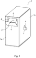
- Fig. 1 presents an oblique top and side view of one installation pack according to the invention, which comprises at least a packing case 1 and inside it a reel 6, onto which the flexible member 2 to be installed, such as a suspension member, a hoisting member, a traction member or a current & data cable of an elevator, is wound.
- the packing case 1 comprises at least a lid, a base, a front side wall 1a, a rear side wall and side walls 1b, and at least both the base and the side walls 1b are preferably reinforced.
- Both side walls 1b have an aperture 3 pointing obliquely downwards in two directions, the first end of which aperture points obliquely downwards towards the front wall 1a of the packing case 1 and the second end of which aperture points obliquely downwards towards the rear wall of the packing case 1.
- the reel 6 is configured to be supported by its shaft 7 in the aperture 3 of the side walls 1b.
- the apertures 3 function as installation means and as a rotational support for supporting the reel in a manner that allows rotation inside the packing case 1.
- the rotational supports of the rotating shaft 7 can also be fitted entirely inside the packing case 1 on the inside surface of both side walls 1b.
- the aforementioned inside surfaces can have grooves the shape of the aperture 3, which grooves do not, however, extend through the side wall 1b to the outside of the side wall 1b.
- the front wall 1a of the packing case 1 has an aperture 5, which comprises an openable lid part 4, which is opened during the installation of the flexible member 2 so that the flexible member 2 is able to discharge from the reel 6 to the disposal location.
- the whole installation pack is made from environmentally benign recycling materials, which can be delivered for recycling after installation of the flexible member 2.
- the packing case 1 which is essentially a rectangular prism in shape, is a material composed of vegetable fiber, preferably of wood fiber, such as cardboard, e.g. corrugated cardboard, which is folded into the necessary number of layers one on top of another.
- the body of the reel 6 is fabricated from vegetable fibers, preferably from wood fibers pressed together or from another type of cardboard, or also from wood.
- the shaft 7 of the reel 6 is also fabricated from vegetable fibers, preferably e.g. from wood fibers pressed together, or the shaft can also be a shaft turned from wood.
- Figs. 2 and 3 present a sectioned side view of one installation pack according to the invention.
- the reel 6 is in its first position inside the packing case 1 detached from the inside base 8 of the packing case.
- the reel 6 is supported by its shaft 7, in a manner that allows essentially free rotation, in the first end of the apertures 3. This position allows the reel 6 to rotate essentially freely.
- the reel 6 can be disposed in its second position presented by Fig. 3 such that the shaft 7 of the reel 6 is shifted to the second end of the aperture 3, which second end is lower than the first end.
- the outer rim of the reel 6 hits the inside base 8 of the packing case 1, in which case the friction produced by abrasive contact suitably brakes the rotation of the reel 6.
- Fig. 4 presents one installation pack according to the invention, as viewed from the front of the packing case 1. From Fig. 4 it is clearly seen how the ends of the rotating shaft 7 of the reel 6 extend in both directions out from the side walls 1b of the packing case 1 while resting on the apertures 3 that are in the side walls 1b and that are a resting support and rotational support of the rotating shaft 7.
- Fig. 5 presents in more detail a side wall 1b of a packing case 1 of an installation pack according to the invention, as viewed from the side.
- the aperture 3 in the side wall 1b, said aperture supporting the shaft 7 of the reel 6, has two branches, which branches both point obliquely downwards.
- the first end 3a of the aperture 3 points obliquely downwards towards the front wall 1a of the packing case 1 and the second end 3b of the aperture 3 points obliquely downwards at essentially the same angle towards the rear wall of the packing case 1.
- the first end 3a of the aperture 3 is shorter than the second end 3b, so that the first end 3a of the aperture 3 is farther from the inside base 8 of the packing case 1 than the second end 3b of the aperture 3.
- the distance of the aperture 3 from the inside base 8 is dimensioned in relation to the diameter of the reel 6 to be such that when the shaft 7 of the reel 6 is at the first end 3a of the aperture 3, the outer rim of the reel 6 is detached from the inside base 8 of the packing case 1 and correspondingly when the shaft 7 of the reel 6 is at the second end 3b of the aperture 3, the outer rim of the reel 6 rests at the same time on the inside base 8 of the packing case 1 for achieving a braking effect on the rotation of the reel 6.
- one or more packing cases 1 with reel(s) 6 are disposed in the installation phase of the flexible members 2 side-by-side on a level of a building, such as on a floor level, on the floor of the elevator hoistway or on the floor of the machine room, and all the flexible members 2 to be installed in the same context are fed into the elevator system at the same time by discharging the flexible member 2 from reels 6 rotating in their position inside a packing case 1 to be used as a reeling rack e.g. by pulling the flexible member 2 out of the packing case 1 with the elevator's own machine or with another suitable machine.
- the rotating shaft 7 of the reel 6 Before the discharging of the flexible member 2 from the packing case 1 the rotating shaft 7 of the reel 6 is disposed in the first end 3a of the aperture 3, after which the reel 6 is rotated in the first end 3a of the aperture 3 by pulling the flexible member 2 out from the reel 6.
- the rotation of the reel 6 is braked, if necessary, by shifting the rotating shaft 7 of the reel 6 to the second end 3b of the aperture 3 and by letting the outer rim 6a of the reel 6 rotate against the inside base 8 of the packing case 1.
- the reel 6 is rotated inside the packing case 1 while supported on the packing case 1 for essentially the whole time of feeding in the flexible member 2.
- the reel 6 is supported via its shaft 7 on the aperture 3 and at the same time on the side walls 1b of the packing case 1, and when the reel 6 is rotating in the second end 3b of the aperture 3, the reel 6 is mainly supported on the inside base 8 of the packing case 1, but receives its guidance from the aperture 3.
- the reel can, if necessary, be braked otherwise than by letting the outer rim of the reel abrade the inside base of the packing case.
- the side walls of a packing case can e.g. at a suitable point have holes, into which can be placed cardboard or wooden pins, against which the reel can, by suitable shifting, be made to rotate.
Landscapes
- Engineering & Computer Science (AREA)
- Mechanical Engineering (AREA)
- Packaging Of Annular Or Rod-Shaped Articles, Wearing Apparel, Cassettes, Or The Like (AREA)
- Packaging Of Machine Parts And Wound Products (AREA)
- Escalators And Moving Walkways (AREA)
- Lift-Guide Devices, And Elevator Ropes And Cables (AREA)
- Types And Forms Of Lifts (AREA)
Description
- The object of the invention is an installation pack as presented in the preamble of
claim 1 and an arrangement as presented inclaim 4 for installing in an elevator a flexible member, such as a hoisting member, a traction member or a current & data cable, of an elevator. - Nowadays the delivery of the flexible members of an elevator, such as the hoisting ropes of an elevator, is implemented in separate cardboard boxes, in which is a reel fabricated from wood and/or metal, onto which the flexible member is prewound. In the installation phase the reel is taken out of the packing case and fitted onto a separate installation rack functioning as a tool, from which the flexible member, such as rope, can be unreeled in order to prevent twisting of the flexible member. Twisting would produce abrupt loops that would make installation of the flexible member more difficult. When unreeling a flexible member, such as rope, the rotation of the reel must be restricted to prevent uncontrolled discharge of the rope from the reel when the reel rotates momentarily faster than the rope can be fed into the roping to be formed.
- In the solutions known in the art the flexible members, such as ropes, of elevators are installed one at a time with a type of discharge device that is designed so that free rotation of the rope with the reeling device is prevented by the aid of spring force. In this case greater friction is achieved by tightening the spring and free discharge of the rope from the reel is prevented. Additionally, it is known for a helper to brake the reel e.g. manually or by the aid of some auxiliary device.
- There are, however, significant drawbacks attached to prior art. Regulation of the discharge device described above is difficult and so it often happens that the flexible member, such as rope, either discharges too quickly or does not discharge at all. In addition, e.g. the simultaneous discharge of ropes with prior-art devices is difficult. Thus installation of the roping becomes more difficult and takes a lot of time. Another problem is the need for the aforementioned installation racks, because there is no other use for the installation racks. Nevertheless, very many installation racks are needed in connection with installation, because elevator models are often different and often many elevators are installed at one time. The storage of the aforementioned installation racks and their transfer from the store to the worksite and back to the store is both expensive and ecologically detrimental to the environment.
- The
JP 2002053271 A US 2003/0085080 A1 as well as theUS 2006/0255203 A1 disclose an installation pack according to the preamble ofclaim 1 . - The aim of the present invention is to eliminate the aforementioned drawbacks and to achieve a cheap, ecofriendly, operationally reliable and easily implemented arrangement for installing in an elevator a flexible member, such as a hoisting member, a traction member or a current & data cable, of an elevator. A hoisting member and traction member can be e.g. a belt or a rope. Additionally the purpose of the invention is to achieve an ecofriendly installation pack of the flexible member, which pack can be delivered for recycling after use. The installation pack according to the invention is characterized by what is disclosed in
claim 1 and the arrangement according to the invention is characterized byclaim 4 . Preferred embodiments of the invention are subject matter of the corresponding dependent claims. - Some inventive embodiments are also discussed in the descriptive section of the present application. Likewise the different details presented in connection with each embodiment can also be applied in other embodiments. In addition it can be stated that at least some of the subordinate claims can in at least some situations be deemed to be inventive in their own right.
- By means of the invention significant advantages are achieved. Thus, the self-weight of a reel and a flexible member, such as a rope, ensures a reliable braking force is achieved. Since the discharge speed of a flexible member, such as a rope, from the reel in connection with installation can be e.g. approx. 10 m/s, or even more, it must be possible to stop the reel reliably immediately the discharge of the flexible member ends. When the reel is lowered onto the base of the packing case, the ratio of rotation force and weight is generally essentially constant in connection with braking.
- One advantage of the solution according to the invention is also that the packing case of the flexible member simultaneously functions as an installation rack when the flexible member is unreeled to the disposal location. Thus surplus installation racks, storage locations of them, and also transfers of them between the installation location and the storage location are not needed at all because the packing case itself also functions as an installation rack.
- Another advantage is that the aforementioned flexible members are all the time before installation in the packing case in a space that is well protected from humidity and dust and that does not need to be opened before installation. Another advantage is that both the reels and all the structures needed for protecting the reels and for reeling a flexible member into the disposal location are recyclable and environmentally benign. A further advantage is also that the reel according to the invention is very quickly deployed because separate installation racks are not needed.
- In the following the invention will be described in more detail by the aid of some examples of its embodiment with reference to the attached simplified drawings, wherein
- Fig. 1
- presents an oblique view from the top and side of one installation pack according to the invention,
- Fig. 2
- presents a sectioned side view of one installation pack according to the invention, when the reel is in its first position,
- Fig. 3
- presents a sectioned side view of one installation pack according to the invention, when the reel is in its second position,
- Fig. 4
- presents a front view of one installation pack according to the invention,
- Fig. 5
- presents an installation pack according to the invention, as viewed from the side of the side wall of the packing case, and
- Fig. 6
- presents an arrangement comprising two packing cases.
- The idea of the solution according to the invention is that for installation purposes a
flexible member 2, such as a suspension member, a hoisting member, a traction member or a current & data cable of an elevator, wound onto areel 6 is delivered to the installation worksite in an installation pack, which comprises at least apacking case 1, inside which is theflexible member 2 wound onto areel 6. Theflexible member 2, being a suspension member, hoisting member and traction member, is e.g. a belt or a rope, which rope is preferably essentially small in diameter, i.e. a so-called thin rope, e.g. approx. 3-8 mm in diameter, suitably e.g. approx. 4 mm. Thepacking case 1 forms a storage-time and transportation-time protection and, in addition, during the installation supports thereel 6 in its position while allowing it to rotate, forming an installation-time installation rack, in which case a separate installation rack is not needed for supporting thereel 6 in its position while allowing it to rotate. In practice a number of these types of installation packs are placed side-by-side on a level in the building, such as on a floor level or on the floor of the elevator hoistway or of the machine room, in the installation phase of the elevator, and theflexible member 2 on thereel 6 is pulled by unreeling into the elevator system, e.g. by threading theflexible member 2, such as a suspension rope, from thereel 6 directly onto the diverting pulleys of the elevator. -
Fig. 1 presents an oblique top and side view of one installation pack according to the invention, which comprises at least apacking case 1 and inside it areel 6, onto which theflexible member 2 to be installed, such as a suspension member, a hoisting member, a traction member or a current & data cable of an elevator, is wound. Thepacking case 1 comprises at least a lid, a base, afront side wall 1a, a rear side wall andside walls 1b, and at least both the base and theside walls 1b are preferably reinforced. Bothside walls 1b have anaperture 3 pointing obliquely downwards in two directions, the first end of which aperture points obliquely downwards towards thefront wall 1a of thepacking case 1 and the second end of which aperture points obliquely downwards towards the rear wall of thepacking case 1. Thereel 6 is configured to be supported by itsshaft 7 in theaperture 3 of theside walls 1b. Theapertures 3 function as installation means and as a rotational support for supporting the reel in a manner that allows rotation inside thepacking case 1. Instead ofapertures 3, the rotational supports of the rotatingshaft 7 can also be fitted entirely inside thepacking case 1 on the inside surface of bothside walls 1b. In this case the aforementioned inside surfaces can have grooves the shape of theaperture 3, which grooves do not, however, extend through theside wall 1b to the outside of theside wall 1b. In addition, thefront wall 1a of thepacking case 1 has anaperture 5, which comprises anopenable lid part 4, which is opened during the installation of theflexible member 2 so that theflexible member 2 is able to discharge from thereel 6 to the disposal location. - The whole installation pack is made from environmentally benign recycling materials, which can be delivered for recycling after installation of the
flexible member 2. Thepacking case 1, which is essentially a rectangular prism in shape, is a material composed of vegetable fiber, preferably of wood fiber, such as cardboard, e.g. corrugated cardboard, which is folded into the necessary number of layers one on top of another. Correspondingly, the body of thereel 6 is fabricated from vegetable fibers, preferably from wood fibers pressed together or from another type of cardboard, or also from wood. Additionally, theshaft 7 of thereel 6 is also fabricated from vegetable fibers, preferably e.g. from wood fibers pressed together, or the shaft can also be a shaft turned from wood. -
Figs. 2 and 3 present a sectioned side view of one installation pack according to the invention. In the situation according toFig. 2 , thereel 6 is in its first position inside thepacking case 1 detached from theinside base 8 of the packing case. In this case thereel 6 is supported by itsshaft 7, in a manner that allows essentially free rotation, in the first end of theapertures 3. This position allows thereel 6 to rotate essentially freely. If, however, braking is needed for the rotating of thereel 6, thereel 6 can be disposed in its second position presented byFig. 3 such that theshaft 7 of thereel 6 is shifted to the second end of theaperture 3, which second end is lower than the first end. In this case the outer rim of thereel 6 hits theinside base 8 of thepacking case 1, in which case the friction produced by abrasive contact suitably brakes the rotation of thereel 6. -
Fig. 4 presents one installation pack according to the invention, as viewed from the front of thepacking case 1. FromFig. 4 it is clearly seen how the ends of therotating shaft 7 of thereel 6 extend in both directions out from theside walls 1b of thepacking case 1 while resting on theapertures 3 that are in theside walls 1b and that are a resting support and rotational support of therotating shaft 7. -
Fig. 5 presents in more detail aside wall 1b of apacking case 1 of an installation pack according to the invention, as viewed from the side. Theaperture 3 in theside wall 1b, said aperture supporting theshaft 7 of thereel 6, has two branches, which branches both point obliquely downwards. Thefirst end 3a of theaperture 3 points obliquely downwards towards thefront wall 1a of thepacking case 1 and thesecond end 3b of theaperture 3 points obliquely downwards at essentially the same angle towards the rear wall of thepacking case 1. Thefirst end 3a of theaperture 3 is shorter than thesecond end 3b, so that thefirst end 3a of theaperture 3 is farther from theinside base 8 of thepacking case 1 than thesecond end 3b of theaperture 3. The distance of theaperture 3 from theinside base 8 is dimensioned in relation to the diameter of thereel 6 to be such that when theshaft 7 of thereel 6 is at thefirst end 3a of theaperture 3, the outer rim of thereel 6 is detached from theinside base 8 of thepacking case 1 and correspondingly when theshaft 7 of thereel 6 is at thesecond end 3b of theaperture 3, the outer rim of thereel 6 rests at the same time on theinside base 8 of thepacking case 1 for achieving a braking effect on the rotation of thereel 6. - In the installation pack and in the arrangement according to the invention one or
more packing cases 1 with reel(s) 6 are disposed in the installation phase of theflexible members 2 side-by-side on a level of a building, such as on a floor level, on the floor of the elevator hoistway or on the floor of the machine room, and all theflexible members 2 to be installed in the same context are fed into the elevator system at the same time by discharging theflexible member 2 fromreels 6 rotating in their position inside apacking case 1 to be used as a reeling rack e.g. by pulling theflexible member 2 out of thepacking case 1 with the elevator's own machine or with another suitable machine. - Before the discharging of the
flexible member 2 from thepacking case 1 therotating shaft 7 of thereel 6 is disposed in thefirst end 3a of theaperture 3, after which thereel 6 is rotated in thefirst end 3a of theaperture 3 by pulling theflexible member 2 out from thereel 6. The rotation of thereel 6 is braked, if necessary, by shifting therotating shaft 7 of thereel 6 to thesecond end 3b of theaperture 3 and by letting theouter rim 6a of thereel 6 rotate against theinside base 8 of thepacking case 1. - The
reel 6 is rotated inside thepacking case 1 while supported on thepacking case 1 for essentially the whole time of feeding in theflexible member 2. When thereel 6 is rotating in thefirst end 3a of theaperture 3, thereel 6 is supported via itsshaft 7 on theaperture 3 and at the same time on theside walls 1b of thepacking case 1, and when thereel 6 is rotating in thesecond end 3b of theaperture 3, thereel 6 is mainly supported on theinside base 8 of thepacking case 1, but receives its guidance from theaperture 3. After the feeding in of theflexible members 2 and when thereels 6 are empty, thepacking cases 1 with theirreels 6 andshafts 7 are delivered for recycling. - It should also be noted that the different solutions presented above can be inventive features together with one or more other features of the invention.
- It is obvious to the person skilled in the art that the invention is not limited solely to the examples described above, but that it may be varied within the scope of the claims presented below. Thus, for example, the shape, structure and operation of the packing case and reel as well as of the rotating shaft can also be different to what is presented above.
- It is also obvious to a person skilled in the art that the reel can, if necessary, be braked otherwise than by letting the outer rim of the reel abrade the inside base of the packing case. The side walls of a packing case can e.g. at a suitable point have holes, into which can be placed cardboard or wooden pins, against which the reel can, by suitable shifting, be made to rotate.
Claims (5)
- Installation pack of a flexible member (2), such as a rope, belt or cable, of an elevator, which installation pack comprises a packing case (1), inside which is a reel (6), onto which a flexible member (2) of an elevator is wound, which installation pack comprises means (3, 7) for supporting the reel (6) in its position in a manner that allows rotation inside the packing case (1), whereby the means (3, 7) for supporting the reel (6) in its position in a manner that allows rotation inside the packing case (1) comprise at least a rotating shaft (7) and a rotational support, being an edge of an aperture (3) in both side walls of the packing case (1), on which rotational support the rotating shaft (7) is disposed to rest, characterized in that the aperture (3) is arranged to point obliquely downwards in two directions such that a first end (3a) of the aperture (3) points obliquely downwards towards the front wall (1a) of the packing case (1) and a second end (3b) of the aperture (3) points obliquely downwards towards the rear wall of the packing case (1), and in that the second end (3b) of the aperture (3) is closer to the inside base (8) of the packing case (1) than the first end (3a) of the aperture (3).
- Installation pack according to claim 1, characterized in that the distance of the first end (3a) of the aperture (3) from the inside base (8) of the packing case (1) is configured to be greater than the diameter of the reel (6) such that the reel (6) can rotate around the shaft (7) disposed in the first end (3a) of the aperture (3) without touching the inside base (8) of the packing case (1), and in that the distance of the second end (3b) of the aperture (3) from the inside base (8) of the packing case (1) is configured to be such, in relation to the diameter of the reel (6), that when the shaft (7) of the reel (6) is disposed in the second end (3b) of the aperture (3) the outer rim of the reel (6) hits the inside base (8) of the packing case (1).
- Installation pack according to any of the preceding claims 1 to 2, characterized in that the packing case (1), reel (6) and its rotating shaft (7) are of recycling material fabricated from vegetable fibers, preferably material fabricated from wood fibers, such as cardboard, material pressed from wood fibers and/or wood.
- Arrangement comprising one or more installation packs according to one of the claims 1 to 3, wherein the reel (6) is supported in its position in a manner allowing rotation inside the packing case (1) when pulling the flexible member (2) from the reel (6) into an elevator system.
- Arrangement according to claim 4, characterized in that for feeding the flexible member (2) into the elevator, the rotating shaft (7) of the reel (6) is disposed in the first end (3a) of the aperture (3), and in that when braking of the rotation of the reel (6) is needed, the rotating shaft (7) of the reel (6) is disposed in the second end (3b) of the aperture (3), which second end is closer to the inside base (8) of the packing case (1) so that the outer rim (6a) of the reel (6) extends against the inside base (8) of the packing case (1).
Applications Claiming Priority (2)
| Application Number | Priority Date | Filing Date | Title |
|---|---|---|---|
| FI20115934A FI125126B (en) | 2011-09-23 | 2011-09-23 | Procedure and arrangement for installing a flexible member in an elevator and installation package for a flexible member |
| PCT/FI2012/050907 WO2013041771A1 (en) | 2011-09-23 | 2012-09-20 | Method and arrangement for installing a flexible member in an elevator and installation pack of the flexible member |
Publications (3)
| Publication Number | Publication Date |
|---|---|
| EP2758331A1 EP2758331A1 (en) | 2014-07-30 |
| EP2758331A4 EP2758331A4 (en) | 2015-05-06 |
| EP2758331B1 true EP2758331B1 (en) | 2016-04-13 |
Family
ID=44718839
Family Applications (1)
| Application Number | Title | Priority Date | Filing Date |
|---|---|---|---|
| EP12834273.0A Not-in-force EP2758331B1 (en) | 2011-09-23 | 2012-09-20 | Installation pack and arrangement for installing a flexible member in an elevator |
Country Status (4)
| Country | Link |
|---|---|
| EP (1) | EP2758331B1 (en) |
| CN (1) | CN103842279B (en) |
| FI (1) | FI125126B (en) |
| WO (1) | WO2013041771A1 (en) |
Families Citing this family (11)
| Publication number | Priority date | Publication date | Assignee | Title |
|---|---|---|---|---|
| US9617112B1 (en) * | 2009-10-23 | 2017-04-11 | Southwire Company, Llc | Independently rotatable flanges and attachable arbor hole adapters |
| USD817893S1 (en) | 2016-06-23 | 2018-05-15 | Southwire Company, Llc | Flange with hook aperture |
| EP2845832B1 (en) | 2013-09-05 | 2017-07-26 | KONE Corporation | A rope storage unit, a method for installing elevator and a method for fabricating rope storage unit |
| US9446928B2 (en) * | 2014-01-17 | 2016-09-20 | Honeywell International Inc. | Inertia braking payout device and package system |
| EP3034449A1 (en) | 2014-12-17 | 2016-06-22 | KONE Corporation | Rope storage unit and method for installing elevator ropes |
| US10766735B2 (en) | 2015-08-19 | 2020-09-08 | Southwire Company, Llc | Flange stand and adapter for flanges |
| CN105292802A (en) * | 2015-11-28 | 2016-02-03 | 无锡飞环包装器材有限公司 | Wire packing box convenient to take and use |
| USD818440S1 (en) | 2016-06-23 | 2018-05-22 | Southwire Company, Llc | Flange with kidney aperture |
| DE102016224176B3 (en) * | 2016-12-06 | 2017-12-21 | Technisat Digital Gmbh | Apparatus and method for unwinding a material from a supply drum |
| CN109119928B (en) * | 2017-02-11 | 2020-03-27 | 烟台知兴知识产权咨询服务有限公司 | Power cable conveyer |
| JP6811161B2 (en) * | 2017-11-17 | 2021-01-13 | 株式会社日立製作所 | Elevator rope installation jigs |
Family Cites Families (8)
| Publication number | Priority date | Publication date | Assignee | Title |
|---|---|---|---|---|
| US4168778A (en) * | 1978-04-24 | 1979-09-25 | Bemis Company, Inc. | Dispensing package |
| US5704479A (en) * | 1995-12-05 | 1998-01-06 | Essex Group, Inc. | Wire storing and dispensing package |
| US5967451A (en) * | 1998-07-17 | 1999-10-19 | Radaios; Hristos | Cable wire spool |
| US6533077B1 (en) * | 2000-07-14 | 2003-03-18 | Otis Elevator Company | CSB (installation) dispensing tool and multi-belt hoisting clamp |
| JP4220112B2 (en) * | 2000-08-08 | 2009-02-04 | 東芝エレベータ株式会社 | Tail cord packing structure carrier |
| JP2004051242A (en) * | 2002-07-16 | 2004-02-19 | Mitsubishi Electric Corp | Elevator main cable extension device |
| ES2304676T3 (en) * | 2005-02-02 | 2008-10-16 | Nexans | BOX AND PROCEDURE FOR THE EXPEDITION OF A CABLE COIL. |
| US8016222B2 (en) * | 2008-04-16 | 2011-09-13 | Windy City Wire Cable And Technology Products, Llc | Wire and cable dispensing container and systems |
-
2011
- 2011-09-23 FI FI20115934A patent/FI125126B/en active IP Right Grant
-
2012
- 2012-09-20 CN CN201280046038.1A patent/CN103842279B/en not_active Expired - Fee Related
- 2012-09-20 WO PCT/FI2012/050907 patent/WO2013041771A1/en not_active Ceased
- 2012-09-20 EP EP12834273.0A patent/EP2758331B1/en not_active Not-in-force
Also Published As
| Publication number | Publication date |
|---|---|
| FI20115934A0 (en) | 2011-09-23 |
| EP2758331A1 (en) | 2014-07-30 |
| CN103842279B (en) | 2016-08-31 |
| HK1197223A1 (en) | 2015-01-09 |
| EP2758331A4 (en) | 2015-05-06 |
| FI125126B (en) | 2015-06-15 |
| FI20115934L (en) | 2013-03-24 |
| CN103842279A (en) | 2014-06-04 |
| WO2013041771A1 (en) | 2013-03-28 |
Similar Documents
| Publication | Publication Date | Title |
|---|---|---|
| EP2758331A1 (en) | Method and arrangement for installing a flexible member in an elevator and installation pack of the flexible member | |
| EP2896586B1 (en) | Inertia braking payout device and package system | |
| US20160347573A1 (en) | Cable dispensing system and apparatus | |
| US8708144B2 (en) | Adapter for wire dispensing carton | |
| EP2233420B1 (en) | Dispenser for elongate material | |
| NZ280598A (en) | Package for spool of cable: spool mounted on end plates which are positioned in box | |
| JP2019524599A (en) | Rope storage device and elevator rope installation method | |
| JP2525640B2 (en) | A device for feeding out printed matter wound around the core in a knitting and overlapping knitting together with the winding tape. | |
| EP3342738B1 (en) | Collar retention system for packaging device for dispensing elongated flexible material | |
| JP6435281B2 (en) | Electric hoist | |
| US7819354B2 (en) | Roll holder for tape dispenser and tape dispenser assembly therewith | |
| US20070018031A1 (en) | Wire cable dispenser | |
| HK1197223B (en) | Method and arrangement for installing a flexible member in an elevator and installation pack of the flexible member | |
| KR100982202B1 (en) | Cable reel | |
| JP5671411B2 (en) | Wire rod feeding device | |
| WO2008049965A1 (en) | Fibre-web manufacturing line and a slitter-winder arrangement | |
| JP5859725B2 (en) | Length detector wire guide structure | |
| KR20220123564A (en) | toilet paper holder | |
| CA2331205C (en) | Device for a wound wire that is relatively stiff | |
| US20030090181A1 (en) | Apparatus for supplying items to be used in garages | |
| JP7066421B2 (en) | Hook stopper prevention device and hoisting machine | |
| KR20220137849A (en) | Wrapping machine | |
| US20050127234A1 (en) | Electrical wire dispensing device and package | |
| KR20230131641A (en) | Packing apparatus for optical cable | |
| JP2743258B2 (en) | Safety device for hanging basketball table |
Legal Events
| Date | Code | Title | Description |
|---|---|---|---|
| PUAI | Public reference made under article 153(3) epc to a published international application that has entered the european phase |
Free format text: ORIGINAL CODE: 0009012 |
|
| 17P | Request for examination filed |
Effective date: 20140310 |
|
| AK | Designated contracting states |
Kind code of ref document: A1 Designated state(s): AL AT BE BG CH CY CZ DE DK EE ES FI FR GB GR HR HU IE IS IT LI LT LU LV MC MK MT NL NO PL PT RO RS SE SI SK SM TR |
|
| DAX | Request for extension of the european patent (deleted) | ||
| REG | Reference to a national code |
Ref country code: DE Ref legal event code: R079 Ref document number: 602012017183 Country of ref document: DE Free format text: PREVIOUS MAIN CLASS: B66B0007060000 Ipc: B66B0019020000 |
|
| RA4 | Supplementary search report drawn up and despatched (corrected) |
Effective date: 20150408 |
|
| RIC1 | Information provided on ipc code assigned before grant |
Ipc: B66B 19/02 20060101AFI20150331BHEP Ipc: B65H 49/32 20060101ALI20150331BHEP Ipc: B65D 85/04 20060101ALI20150331BHEP |
|
| GRAP | Despatch of communication of intention to grant a patent |
Free format text: ORIGINAL CODE: EPIDOSNIGR1 |
|
| INTG | Intention to grant announced |
Effective date: 20151111 |
|
| RIN1 | Information on inventor provided before grant (corrected) |
Inventor name: BJOERNI, OSMO Inventor name: FORSSTROEM, NIKO Inventor name: LOFTUS, TONY Inventor name: AHONIEMI, JARMO |
|
| GRAS | Grant fee paid |
Free format text: ORIGINAL CODE: EPIDOSNIGR3 |
|
| GRAA | (expected) grant |
Free format text: ORIGINAL CODE: 0009210 |
|
| RIN1 | Information on inventor provided before grant (corrected) |
Inventor name: AHONIEMI, JARMO Inventor name: LOFTUS, TONY Inventor name: BJOERNI, OSMO Inventor name: FORSSTROEM, NIKO |
|
| AK | Designated contracting states |
Kind code of ref document: B1 Designated state(s): AL AT BE BG CH CY CZ DE DK EE ES FI FR GB GR HR HU IE IS IT LI LT LU LV MC MK MT NL NO PL PT RO RS SE SI SK SM TR |
|
| REG | Reference to a national code |
Ref country code: GB Ref legal event code: FG4D |
|
| REG | Reference to a national code |
Ref country code: AT Ref legal event code: REF Ref document number: 789898 Country of ref document: AT Kind code of ref document: T Effective date: 20160415 Ref country code: CH Ref legal event code: EP |
|
| REG | Reference to a national code |
Ref country code: IE Ref legal event code: FG4D |
|
| REG | Reference to a national code |
Ref country code: DE Ref legal event code: R096 Ref document number: 602012017183 Country of ref document: DE |
|
| REG | Reference to a national code |
Ref country code: LT Ref legal event code: MG4D |
|
| REG | Reference to a national code |
Ref country code: AT Ref legal event code: MK05 Ref document number: 789898 Country of ref document: AT Kind code of ref document: T Effective date: 20160413 |
|
| REG | Reference to a national code |
Ref country code: NL Ref legal event code: MP Effective date: 20160413 Ref country code: FR Ref legal event code: PLFP Year of fee payment: 5 |
|
| PG25 | Lapsed in a contracting state [announced via postgrant information from national office to epo] |
Ref country code: LT Free format text: LAPSE BECAUSE OF FAILURE TO SUBMIT A TRANSLATION OF THE DESCRIPTION OR TO PAY THE FEE WITHIN THE PRESCRIBED TIME-LIMIT Effective date: 20160413 Ref country code: PL Free format text: LAPSE BECAUSE OF FAILURE TO SUBMIT A TRANSLATION OF THE DESCRIPTION OR TO PAY THE FEE WITHIN THE PRESCRIBED TIME-LIMIT Effective date: 20160413 Ref country code: NL Free format text: LAPSE BECAUSE OF FAILURE TO SUBMIT A TRANSLATION OF THE DESCRIPTION OR TO PAY THE FEE WITHIN THE PRESCRIBED TIME-LIMIT Effective date: 20160413 Ref country code: FI Free format text: LAPSE BECAUSE OF FAILURE TO SUBMIT A TRANSLATION OF THE DESCRIPTION OR TO PAY THE FEE WITHIN THE PRESCRIBED TIME-LIMIT Effective date: 20160413 Ref country code: NO Free format text: LAPSE BECAUSE OF FAILURE TO SUBMIT A TRANSLATION OF THE DESCRIPTION OR TO PAY THE FEE WITHIN THE PRESCRIBED TIME-LIMIT Effective date: 20160713 |
|
| PG25 | Lapsed in a contracting state [announced via postgrant information from national office to epo] |
Ref country code: AT Free format text: LAPSE BECAUSE OF FAILURE TO SUBMIT A TRANSLATION OF THE DESCRIPTION OR TO PAY THE FEE WITHIN THE PRESCRIBED TIME-LIMIT Effective date: 20160413 Ref country code: HR Free format text: LAPSE BECAUSE OF FAILURE TO SUBMIT A TRANSLATION OF THE DESCRIPTION OR TO PAY THE FEE WITHIN THE PRESCRIBED TIME-LIMIT Effective date: 20160413 Ref country code: LV Free format text: LAPSE BECAUSE OF FAILURE TO SUBMIT A TRANSLATION OF THE DESCRIPTION OR TO PAY THE FEE WITHIN THE PRESCRIBED TIME-LIMIT Effective date: 20160413 Ref country code: RS Free format text: LAPSE BECAUSE OF FAILURE TO SUBMIT A TRANSLATION OF THE DESCRIPTION OR TO PAY THE FEE WITHIN THE PRESCRIBED TIME-LIMIT Effective date: 20160413 Ref country code: GR Free format text: LAPSE BECAUSE OF FAILURE TO SUBMIT A TRANSLATION OF THE DESCRIPTION OR TO PAY THE FEE WITHIN THE PRESCRIBED TIME-LIMIT Effective date: 20160714 Ref country code: PT Free format text: LAPSE BECAUSE OF FAILURE TO SUBMIT A TRANSLATION OF THE DESCRIPTION OR TO PAY THE FEE WITHIN THE PRESCRIBED TIME-LIMIT Effective date: 20160816 Ref country code: ES Free format text: LAPSE BECAUSE OF FAILURE TO SUBMIT A TRANSLATION OF THE DESCRIPTION OR TO PAY THE FEE WITHIN THE PRESCRIBED TIME-LIMIT Effective date: 20160413 Ref country code: SE Free format text: LAPSE BECAUSE OF FAILURE TO SUBMIT A TRANSLATION OF THE DESCRIPTION OR TO PAY THE FEE WITHIN THE PRESCRIBED TIME-LIMIT Effective date: 20160413 |
|
| PG25 | Lapsed in a contracting state [announced via postgrant information from national office to epo] |
Ref country code: BE Free format text: LAPSE BECAUSE OF FAILURE TO SUBMIT A TRANSLATION OF THE DESCRIPTION OR TO PAY THE FEE WITHIN THE PRESCRIBED TIME-LIMIT Effective date: 20160413 Ref country code: IT Free format text: LAPSE BECAUSE OF FAILURE TO SUBMIT A TRANSLATION OF THE DESCRIPTION OR TO PAY THE FEE WITHIN THE PRESCRIBED TIME-LIMIT Effective date: 20160413 |
|
| REG | Reference to a national code |
Ref country code: DE Ref legal event code: R097 Ref document number: 602012017183 Country of ref document: DE |
|
| PG25 | Lapsed in a contracting state [announced via postgrant information from national office to epo] |
Ref country code: CZ Free format text: LAPSE BECAUSE OF FAILURE TO SUBMIT A TRANSLATION OF THE DESCRIPTION OR TO PAY THE FEE WITHIN THE PRESCRIBED TIME-LIMIT Effective date: 20160413 Ref country code: EE Free format text: LAPSE BECAUSE OF FAILURE TO SUBMIT A TRANSLATION OF THE DESCRIPTION OR TO PAY THE FEE WITHIN THE PRESCRIBED TIME-LIMIT Effective date: 20160413 Ref country code: DK Free format text: LAPSE BECAUSE OF FAILURE TO SUBMIT A TRANSLATION OF THE DESCRIPTION OR TO PAY THE FEE WITHIN THE PRESCRIBED TIME-LIMIT Effective date: 20160413 Ref country code: RO Free format text: LAPSE BECAUSE OF FAILURE TO SUBMIT A TRANSLATION OF THE DESCRIPTION OR TO PAY THE FEE WITHIN THE PRESCRIBED TIME-LIMIT Effective date: 20160413 Ref country code: SK Free format text: LAPSE BECAUSE OF FAILURE TO SUBMIT A TRANSLATION OF THE DESCRIPTION OR TO PAY THE FEE WITHIN THE PRESCRIBED TIME-LIMIT Effective date: 20160413 |
|
| PLBE | No opposition filed within time limit |
Free format text: ORIGINAL CODE: 0009261 |
|
| STAA | Information on the status of an ep patent application or granted ep patent |
Free format text: STATUS: NO OPPOSITION FILED WITHIN TIME LIMIT |
|
| PG25 | Lapsed in a contracting state [announced via postgrant information from national office to epo] |
Ref country code: SM Free format text: LAPSE BECAUSE OF FAILURE TO SUBMIT A TRANSLATION OF THE DESCRIPTION OR TO PAY THE FEE WITHIN THE PRESCRIBED TIME-LIMIT Effective date: 20160413 |
|
| 26N | No opposition filed |
Effective date: 20170116 |
|
| PG25 | Lapsed in a contracting state [announced via postgrant information from national office to epo] |
Ref country code: MC Free format text: LAPSE BECAUSE OF FAILURE TO SUBMIT A TRANSLATION OF THE DESCRIPTION OR TO PAY THE FEE WITHIN THE PRESCRIBED TIME-LIMIT Effective date: 20160413 |
|
| REG | Reference to a national code |
Ref country code: CH Ref legal event code: PL |
|
| PG25 | Lapsed in a contracting state [announced via postgrant information from national office to epo] |
Ref country code: SI Free format text: LAPSE BECAUSE OF FAILURE TO SUBMIT A TRANSLATION OF THE DESCRIPTION OR TO PAY THE FEE WITHIN THE PRESCRIBED TIME-LIMIT Effective date: 20160413 |
|
| REG | Reference to a national code |
Ref country code: IE Ref legal event code: MM4A |
|
| PG25 | Lapsed in a contracting state [announced via postgrant information from national office to epo] |
Ref country code: CH Free format text: LAPSE BECAUSE OF NON-PAYMENT OF DUE FEES Effective date: 20160930 Ref country code: LI Free format text: LAPSE BECAUSE OF NON-PAYMENT OF DUE FEES Effective date: 20160930 Ref country code: IE Free format text: LAPSE BECAUSE OF NON-PAYMENT OF DUE FEES Effective date: 20160920 |
|
| PG25 | Lapsed in a contracting state [announced via postgrant information from national office to epo] |
Ref country code: LU Free format text: LAPSE BECAUSE OF NON-PAYMENT OF DUE FEES Effective date: 20160920 |
|
| REG | Reference to a national code |
Ref country code: FR Ref legal event code: PLFP Year of fee payment: 6 |
|
| PG25 | Lapsed in a contracting state [announced via postgrant information from national office to epo] |
Ref country code: HU Free format text: LAPSE BECAUSE OF FAILURE TO SUBMIT A TRANSLATION OF THE DESCRIPTION OR TO PAY THE FEE WITHIN THE PRESCRIBED TIME-LIMIT; INVALID AB INITIO Effective date: 20120920 |
|
| PG25 | Lapsed in a contracting state [announced via postgrant information from national office to epo] |
Ref country code: CY Free format text: LAPSE BECAUSE OF FAILURE TO SUBMIT A TRANSLATION OF THE DESCRIPTION OR TO PAY THE FEE WITHIN THE PRESCRIBED TIME-LIMIT Effective date: 20160413 Ref country code: MT Free format text: LAPSE BECAUSE OF NON-PAYMENT OF DUE FEES Effective date: 20160930 Ref country code: MK Free format text: LAPSE BECAUSE OF FAILURE TO SUBMIT A TRANSLATION OF THE DESCRIPTION OR TO PAY THE FEE WITHIN THE PRESCRIBED TIME-LIMIT Effective date: 20160413 Ref country code: IS Free format text: LAPSE BECAUSE OF FAILURE TO SUBMIT A TRANSLATION OF THE DESCRIPTION OR TO PAY THE FEE WITHIN THE PRESCRIBED TIME-LIMIT Effective date: 20160413 |
|
| PG25 | Lapsed in a contracting state [announced via postgrant information from national office to epo] |
Ref country code: BG Free format text: LAPSE BECAUSE OF FAILURE TO SUBMIT A TRANSLATION OF THE DESCRIPTION OR TO PAY THE FEE WITHIN THE PRESCRIBED TIME-LIMIT Effective date: 20160413 |
|
| REG | Reference to a national code |
Ref country code: FR Ref legal event code: PLFP Year of fee payment: 7 |
|
| PG25 | Lapsed in a contracting state [announced via postgrant information from national office to epo] |
Ref country code: AL Free format text: LAPSE BECAUSE OF FAILURE TO SUBMIT A TRANSLATION OF THE DESCRIPTION OR TO PAY THE FEE WITHIN THE PRESCRIBED TIME-LIMIT Effective date: 20160413 Ref country code: TR Free format text: LAPSE BECAUSE OF FAILURE TO SUBMIT A TRANSLATION OF THE DESCRIPTION OR TO PAY THE FEE WITHIN THE PRESCRIBED TIME-LIMIT Effective date: 20160413 |
|
| PGFP | Annual fee paid to national office [announced via postgrant information from national office to epo] |
Ref country code: FR Payment date: 20210921 Year of fee payment: 10 |
|
| PGFP | Annual fee paid to national office [announced via postgrant information from national office to epo] |
Ref country code: DE Payment date: 20210920 Year of fee payment: 10 Ref country code: GB Payment date: 20210920 Year of fee payment: 10 |
|
| REG | Reference to a national code |
Ref country code: DE Ref legal event code: R119 Ref document number: 602012017183 Country of ref document: DE |
|
| GBPC | Gb: european patent ceased through non-payment of renewal fee |
Effective date: 20220920 |
|
| PG25 | Lapsed in a contracting state [announced via postgrant information from national office to epo] |
Ref country code: FR Free format text: LAPSE BECAUSE OF NON-PAYMENT OF DUE FEES Effective date: 20220930 Ref country code: DE Free format text: LAPSE BECAUSE OF NON-PAYMENT OF DUE FEES Effective date: 20230401 |
|
| PG25 | Lapsed in a contracting state [announced via postgrant information from national office to epo] |
Ref country code: GB Free format text: LAPSE BECAUSE OF NON-PAYMENT OF DUE FEES Effective date: 20220920 |