EP2757733B1 - Verfahren und Vorrichtung zur Messung von Kanalstatusinformationen in einem drahtlosen Kommunikationssystem - Google Patents
Verfahren und Vorrichtung zur Messung von Kanalstatusinformationen in einem drahtlosen Kommunikationssystem Download PDFInfo
- Publication number
- EP2757733B1 EP2757733B1 EP14152139.3A EP14152139A EP2757733B1 EP 2757733 B1 EP2757733 B1 EP 2757733B1 EP 14152139 A EP14152139 A EP 14152139A EP 2757733 B1 EP2757733 B1 EP 2757733B1
- Authority
- EP
- European Patent Office
- Prior art keywords
- subframe
- referred
- following
- csi
- scell
- Prior art date
- Legal status (The legal status is an assumption and is not a legal conclusion. Google has not performed a legal analysis and makes no representation as to the accuracy of the status listed.)
- Active
Links
- 238000000034 method Methods 0.000 title claims description 55
- 238000004891 communication Methods 0.000 title claims description 38
- 238000005259 measurement Methods 0.000 title claims description 11
- 230000002776 aggregation Effects 0.000 claims description 6
- 238000004220 aggregation Methods 0.000 claims description 6
- 239000000969 carrier Substances 0.000 claims 2
- 230000008569 process Effects 0.000 description 23
- 230000005540 biological transmission Effects 0.000 description 15
- 230000000737 periodic effect Effects 0.000 description 13
- 238000010586 diagram Methods 0.000 description 9
- 230000004044 response Effects 0.000 description 5
- 238000012545 processing Methods 0.000 description 4
- 230000009471 action Effects 0.000 description 3
- 230000004913 activation Effects 0.000 description 3
- 230000001143 conditioned effect Effects 0.000 description 3
- 238000013461 design Methods 0.000 description 3
- 239000011159 matrix material Substances 0.000 description 3
- 101001018494 Homo sapiens Pro-MCH Proteins 0.000 description 2
- 102100033721 Pro-MCH Human genes 0.000 description 2
- 230000006399 behavior Effects 0.000 description 2
- 238000004590 computer program Methods 0.000 description 2
- 230000009849 deactivation Effects 0.000 description 2
- 230000006870 function Effects 0.000 description 2
- 230000007774 longterm Effects 0.000 description 2
- 238000010295 mobile communication Methods 0.000 description 2
- 230000003287 optical effect Effects 0.000 description 2
- 239000002245 particle Substances 0.000 description 2
- 230000006978 adaptation Effects 0.000 description 1
- 238000013459 approach Methods 0.000 description 1
- 230000000295 complement effect Effects 0.000 description 1
- 230000001419 dependent effect Effects 0.000 description 1
- 238000005516 engineering process Methods 0.000 description 1
- 230000007257 malfunction Effects 0.000 description 1
- 238000012986 modification Methods 0.000 description 1
- 230000004048 modification Effects 0.000 description 1
- 230000008520 organization Effects 0.000 description 1
- 239000005022 packaging material Substances 0.000 description 1
Images

Classifications
-
- H—ELECTRICITY
- H04—ELECTRIC COMMUNICATION TECHNIQUE
- H04J—MULTIPLEX COMMUNICATION
- H04J11/00—Orthogonal multiplex systems, e.g. using WALSH codes
- H04J11/0023—Interference mitigation or co-ordination
-
- H—ELECTRICITY
- H04—ELECTRIC COMMUNICATION TECHNIQUE
- H04L—TRANSMISSION OF DIGITAL INFORMATION, e.g. TELEGRAPHIC COMMUNICATION
- H04L5/00—Arrangements affording multiple use of the transmission path
- H04L5/003—Arrangements for allocating sub-channels of the transmission path
- H04L5/0053—Allocation of signaling, i.e. of overhead other than pilot signals
- H04L5/0057—Physical resource allocation for CQI
-
- H—ELECTRICITY
- H04—ELECTRIC COMMUNICATION TECHNIQUE
- H04W—WIRELESS COMMUNICATION NETWORKS
- H04W72/00—Local resource management
- H04W72/20—Control channels or signalling for resource management
- H04W72/23—Control channels or signalling for resource management in the downlink direction of a wireless link, i.e. towards a terminal
-
- H—ELECTRICITY
- H04—ELECTRIC COMMUNICATION TECHNIQUE
- H04B—TRANSMISSION
- H04B7/00—Radio transmission systems, i.e. using radiation field
- H04B7/24—Radio transmission systems, i.e. using radiation field for communication between two or more posts
- H04B7/26—Radio transmission systems, i.e. using radiation field for communication between two or more posts at least one of which is mobile
- H04B7/2612—Arrangements for wireless medium access control, e.g. by allocating physical layer transmission capacity
-
- H—ELECTRICITY
- H04—ELECTRIC COMMUNICATION TECHNIQUE
- H04L—TRANSMISSION OF DIGITAL INFORMATION, e.g. TELEGRAPHIC COMMUNICATION
- H04L5/00—Arrangements affording multiple use of the transmission path
- H04L5/003—Arrangements for allocating sub-channels of the transmission path
- H04L5/0053—Allocation of signaling, i.e. of overhead other than pilot signals
-
- H—ELECTRICITY
- H04—ELECTRIC COMMUNICATION TECHNIQUE
- H04W—WIRELESS COMMUNICATION NETWORKS
- H04W24/00—Supervisory, monitoring or testing arrangements
- H04W24/10—Scheduling measurement reports ; Arrangements for measurement reports
-
- H—ELECTRICITY
- H04—ELECTRIC COMMUNICATION TECHNIQUE
- H04W—WIRELESS COMMUNICATION NETWORKS
- H04W72/00—Local resource management
- H04W72/20—Control channels or signalling for resource management
-
- H—ELECTRICITY
- H04—ELECTRIC COMMUNICATION TECHNIQUE
- H04L—TRANSMISSION OF DIGITAL INFORMATION, e.g. TELEGRAPHIC COMMUNICATION
- H04L5/00—Arrangements affording multiple use of the transmission path
- H04L5/0001—Arrangements for dividing the transmission path
- H04L5/0003—Two-dimensional division
- H04L5/0005—Time-frequency
- H04L5/0007—Time-frequency the frequencies being orthogonal, e.g. OFDM(A), DMT
- H04L5/001—Time-frequency the frequencies being orthogonal, e.g. OFDM(A), DMT the frequencies being arranged in component carriers
-
- H—ELECTRICITY
- H04—ELECTRIC COMMUNICATION TECHNIQUE
- H04W—WIRELESS COMMUNICATION NETWORKS
- H04W72/00—Local resource management
- H04W72/50—Allocation or scheduling criteria for wireless resources
- H04W72/51—Allocation or scheduling criteria for wireless resources based on terminal or device properties
Definitions
- This disclosure generally relates to wireless communication networks, and more particularly, to methods and apparatuses for channel state information measurement in a wireless communication system.
- IP Internet Protocol
- E-UTRAN Evolved Universal Terrestrial Radio Access Network
- the E-UTRAN system can provide high data throughput in order to realize the above-noted voice over IP and multimedia services.
- the E-UTRAN system's standardization work is currently being performed by the 3GPP standards organization. Accordingly, changes to the current body of 3GPP standard are currently being submitted and considered to evolve and finalize the 3GPP standard.
- 3GPP R2-110149 provides a discussion on SCell activation/deactivation and CQI reporting and 3GPP R1-110069 provides a discussion in respect to CSI reporting and SRS timing upon SCell activation/deactivation, wherein a UE behavior is considered when a SCell is deactivated, i.e. when the UE cannot find a valid reference resource on that SCell, and even requires some latency for measurement after the activation.
- US 2012/0207047 A1 relates to priority rules of periodic CSI reporting in carrier aggregation and discusses which feedback type is to be prioritized in case the UE has to report to multiple feedback types.
- WO 2012/115364 A2 relates to a method in apparatus for transmitting channel status information to a macro base-station by a relay node in a wireless communication system to which carrier aggregation is applied. It is described that it might be that a valid reference cannot be found due to the relay restriction.
- the method according to a first aspect includes selecting a subframe to be a reference resource for a channel state information (CSI) report on a Secondary Cell (SCell), in which the subframe is not a downlink (DL) subframe or a special subframe whose downlink portion is with a length longer than a threshold on a Primary Cell (PCell). This method further includes executing a handling.
- CSI channel state information
- SCell Secondary Cell
- This method further includes executing a handling.
- Wireless communication systems are widely deployed to provide various types of communication such as voice, data, and so on. These systems may be based on code division multiple access (CDMA), time division multiple access (TDMA), orthogonal frequency division multiple access (OFDMA), 3GPP LTE (Long Term Evolution) wireless access, 3GPP LTE-A or LTE-Advanced (Long Term Evolution Advanced), 3GPP2 UMB (Ultra Mobile Broadband), WiMax, or some other modulation techniques.
- CDMA code division multiple access
- TDMA time division multiple access
- OFDMA orthogonal frequency division multiple access
- 3GPP LTE Long Term Evolution
- 3GPP LTE-A or LTE-Advanced Long Term Evolution Advanced
- 3GPP2 UMB Ultra Mobile Broadband
- WiMax Worldwide Interoperability for Mobile communications
- the exemplary wireless communication systems devices described below may be designed to support one or more standards such as the standard offered by a consortium named "3rd Generation Partnership Project” referred to herein as 3GPP, including Document Nos. R1-124776, "On New Carrier Type ", RP-121415, "New WI proposal: New Carrier Type for LTE ", TS 36.211 V11.1.0, “E-UTRA Physical channels and modulation ", TS 36.213 V11.1.0, “E-UTRA Physical layer procedures ", R1-124717, "On collision between DM RS and PSS/SSS in new carrier ".
- 3GPP 3rd Generation Partnership Project
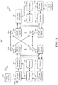
- FIG. 1 shows a multiple access wireless communication system according to one embodiment of the invention.
- An access network 100 includes multiple antenna groups, one including 104 and 106, another including 108 and 110, and an additional including 112 and 114. In FIG. 1 , only two antennas are shown for each antenna group, however, more or fewer antennas may be utilized for each antenna group.
- Access terminal 116 is in communication with antennas 112 and 114, where antennas 112 and 114 transmit information to access terminal 116 over forward link 120 and receive information from access terminal 116 over reverse link 118.
- Access terminal (AT) 122 is in communication with antennas 106 and 108, where antennas 106 and 108 transmit information to access terminal (AT) 122 over forward link 126 and receive information from access terminal (AT) 122 over reverse link 124.
- communication links 118, 120, 124 and 126 may use different frequency for communication.
- forward link 120 may use a different frequency then that used by reverse link 118.
- antenna groups each are designed to communicate to access terminals in a sector of the areas covered by access network 100.
- the transmitting antennas of access network 100 may utilize beamforming in order to improve the signal-to-noise ratio of forward links for the different access terminals 116 and 122. Also, an access network using beamforming to transmit to access terminals scattered randomly through its coverage causes less interference to access terminals in neighboring cells than an access network transmitting through a single antenna to all its access terminals.
- An access network may be a fixed station or base station used for communicating with the terminals and may also be referred to as an access point, a Node B, a base station, an enhanced base station, an eNB, or some other terminology.
- An access terminal may also be called user equipment (UE), a wireless communication device, terminal, access terminal or some other terminology.
- FIG. 2 is a simplified block diagram of an embodiment of a transmitter system 210 (also known as the access network) and a receiver system 250 (also known as access terminal (AT) or user equipment (UE)) in a MIMO system 200.
- a transmitter system 210 also known as the access network
- a receiver system 250 also known as access terminal (AT) or user equipment (UE)
- traffic data for a number of data streams is provided from a data source 212 to a transmit (TX) data processor 214.
- TX transmit
- each data stream is transmitted over a respective transmit antenna.
- TX data processor 214 formats, codes, and interleaves the traffic data for each data stream based on a particular coding scheme selected for that data stream to provide coded data.
- the coded data for each data stream may be multiplexed with pilot data using OFDM techniques.
- the pilot data is typically a known data pattern that is processed in a known manner and may be used at the receiver system to estimate the channel response.
- the multiplexed pilot and coded data for each data stream is then modulated (i.e., symbol mapped) based on a particular modulation scheme (e.g., BPSK, QPSK, M-PSK, or M-QAM) selected for that data stream to provide modulation symbols.
- a particular modulation scheme e.g., BPSK, QPSK, M-PSK, or M-QAM
- the data rate, coding, and modulation for each data stream may be determined by instructions performed by processor 230.
- TX MIMO processor 220 may further process the modulation symbols (e.g., for OFDM).
- TX MIMO processor 220 then provides N T modulation symbol streams to N T transmitters (TMTR) 222a through 222t.
- TMTR TX MIMO processor 220 applies beamforming weights to the symbols of the data streams and to the antenna from which the symbol is being transmitted.
- Each transmitter 222 receives and processes a respective symbol stream to provide one or more analog signals, and further conditions (e.g., amplifies, filters, and upconverts) the analog signals to provide a modulated signal suitable for transmission over the MIMO channel.
- N T modulated signals from transmitters 222a through 222t are then transmitted from N T antennas 224a through 224t, respectively.
- the transmitted modulated signals are received by N R antennas 252a through 252r and the received signal from each antenna 252 is provided to a respective receiver (RCVR) 254a through 254r.
- Each receiver 254 conditions (e.g., filters, amplifies, and downconverts) a respective received signal, digitizes the conditioned signal to provide samples, and further processes the samples to provide a corresponding "received" symbol stream.
- An RX data processor 260 then receives and processes the N R received symbol streams from N R receivers 254 based on a particular receiver processing technique to provide N T "detected" symbol streams.
- the RX data processor 260 then demodulates, deinterleaves, and decodes each detected symbol stream to recover the traffic data for the data stream.
- the processing by RX data processor 260 is complementary to that performed by TX MIMO processor 220 and TX data processor 214 at transmitter system 210.
- a processor 270 periodically determines which pre-coding matrix to use (discussed below). Processor 270 formulates a reverse link message comprising a matrix index portion and a rank value portion.
- the reverse link message may comprise various types of information regarding the communication link and/or the received data stream.
- the reverse link message is then processed by a TX data processor 238, which also receives traffic data for a number of data streams from a data source 236, modulated by a modulator 280, conditioned by transmitters 254a through 254r, and transmitted back to transmitter system 210.
- the modulated signals from receiver system 250 are received by antennas 224, conditioned by receivers 222, demodulated by a demodulator 240, and processed by a RX data processor 242 to extract the reserve link message transmitted by the receiver system 250.
- Processor 230 determines which pre-coding matrix to use for determining the beamforming weights then processes the extracted message.
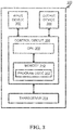
- FIG. 3 shows an alternative simplified functional block diagram of a communication device according to one embodiment of the invention.
- the communication device 300 in a wireless communication system can be utilized for realizing the UEs (or ATs) 116 and 122 in FIG. 1 , and the wireless communications system is preferably the LTE system.
- the communication device 300 includes an input device 302, an output device 304, a control circuit 306, a central processing unit (CPU) 308, a memory 310, a program code 312, and a transceiver 314.
- the control circuit 306 executes the program code 312 in the memory 310 through the CPU 308, thereby controlling an operation of the communications device 300.
- the communications device 300 can receive signals input by a user through the input device 302, such as a keyboard or keypad, and can output images and sounds through the output device 304, such as a monitor or speakers.
- the transceiver 314 is used to receive and transmit wireless signals, delivering received signals to the control circuit 306, and outputting signals generated by the control circuit 306 wirelessly.
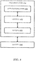
- FIG. 4 is a simplified block diagram of the program code 312 shown in FIG. 3 in accordance with one embodiment of the invention.
- the program code 312 includes an application layer 400, a Layer 3 portion 402, and a Layer 2 portion 404, and is coupled to a Layer 1 portion 406.
- the Layer 3 portion 402 generally performs radio resource control.
- the Layer 2 portion 404 generally performs link control.
- the Layer 1 portion 406 generally performs physical connections.
- the Layer 2 portion may include a Radio Link Control (RLC) layer and a Medium Access Control (MAC) layer.
- the Layer 3 portion may include a Radio Resource Control (RRC) layer.
- RLC Radio Link Control
- MAC Medium Access Control
- RRC Radio Resource Control
- a UE performs channel state information (CSI) measurement based on the definition in TS 36.213 V11.1.0.
- the reference resource is several subframes prior to the CSI reporting subframe such that there is sufficient processing time for the UE to derive the content of CSI report as follows:
- the CSI reference resource for a serving cell is defined as follows:
- the reference resource should be based on a valid downlink subframe whose definition is as follows: A downlink subframe in a serving cell shall be considered to be valid if:
- Time Division Duplexing carrier aggregation
- CA carrier aggregation
- UL uplink
- DL downlink
- a DL subframe n could be considered a valid downlink subframe and also the reference resource for the corresponding CSI report if there is a downlink (DL) subframe n on a secondary cell (SCell) and a periodic CSI report for the SCell will be reported four subframes later.
- the subframe n could be a UL subframe of PCell.
- the UE would report the CSI with useless information because the report would be based on a subframe that the UE may not be able to perform a measurement or a malfunction may occur.
- the evolved Node B eNB
- a handling is done if in the subframe it is not a DL subframe or not a special subframe whose DL part of the special subframe is above a threshold, e.g. it is a special subframe whose DL part of the special subframe is below a threshold or a UL subframe, on a PCell.
- a non-limiting example of the handling is another subframe would be considered as a reference resource.
- Another example of the handling is the CSI report is omitted, e.g. UE skips or does not transmit the CSI report.
- Still another example of the handling is the CSI report contains a specific value.
- a downlink subframe on the SCell would not be considered as a valid downlink subframe if a criterion is fulfilled.
- a criterion is that it is a UL subframe on the PCell in the same subframe.
- Another example of the criterion is that it is a special subframe on the PCell in the same subframe.
- the DL portion of the special subframe is shorter than a threshold. More specifically, a downlink subframe could be considered as a valid downlink subframe if the above criterion is not fulfilled, e.g.
- a downlink subframe is considered as a valid downlink subframe may be subject to other conditions mentioned above, e.g. it does not fall within a configured measurement gap for that UE.
- a first subframe prior to a second sub frame is considered as a reference resource for the CSI report on a SCell if a criterion is fulfilled.
- a criterion is that in the second subframe it is a UL subframe on the PCell.
- Another example of the criterion is that in the second subframe it is a special subframe on the PCell.
- the DL portion of the special subframe is shorter than a threshold.
- a UE would perform an action for a SCell if a criterion is fulfilled.
- the action may be to omit the report, not transmit the report, skip the report, or set the content of the CSI report to a specific value.
- the specific value may be a fixed or predefined value.
- one example of the criterion is that it is a UL subframe on the PCell in the same subframe as the corresponding reference resource of the CSI report.
- another example of the criterion is that it is a special subframe on the PCell in the same subframe as the corresponding reference resource of the CSI report.
- the DL portion of the special subframe is shorter than a threshold.
- an eNB cannot configure some subframe as CSI reporting subframe if a criterion is fulfilled.
- the criterion is that the subframe would result in a reference resource such that in the same subframe of the reference resource of the CSI report it is UL subframe on a PCell.
- Another example of the criterion is that the subframe would result in reference resource such that in the same subframe of the reference resource of the CSI report it is special subframe on a PCell.
- the DL part of the special subframe is shorter than a threshold.
- the CSI report discussed above and herein may refer to one or any combination of an aperiodic CSI report or periodic CSI report.
- a downlink subframe in a serving cell shall be considered to be valid if:
- a downlink subframe in a serving cell shall be considered to be valid if:
- the device 300 includes a program code 312 stored in memory 310.
- the CPU 308 could execute program code 312 to execute one or more of the following: (i) to select a subframe to be a reference resource for a channel state information (CSI) report on a Secondary Cell (SCell), in which the subframe is not a downlink (DL) subframe or special subframe whose downlink portion is longer than a threshold on a Primary Cell (PCell), and (ii) to execute a handling.
- CSI channel state information
- the CPU 308 can execute the program code 312 to perform all of the above-described actions and steps or others described herein, in particular those described in paragraphs [0036] to [0044].
- concurrent channels may be established based on pulse repetition frequencies.
- concurrent channels may be established based on pulse position or offsets.
- concurrent channels may be established based on time hopping sequences.
- concurrent channels may be established based on pulse repetition frequencies, pulse positions or offsets, and time hopping sequences.
- the various illustrative logical blocks, modules, and circuits described in connection with the aspects disclosed herein may be implemented within or performed by an integrated circuit ("IC"), an access terminal, or an access point.
- the IC may comprise a general purpose processor, a digital signal processor (DSP), an application specific integrated circuit (ASIC), a field programmable gate array (FPGA) or other programmable logic device, discrete gate or transistor logic, discrete hardware components, electrical components, optical components, mechanical components, or any combination thereof designed to perform the functions described herein, and may execute codes or instructions that reside within the IC, outside of the IC, or both.
- a general purpose processor may be a microprocessor, but in the alternative, the processor may be any conventional processor, controller, microcontroller, or state machine.
- a processor may also be implemented as a combination of computing devices, e.g., a combination of a DSP and a microprocessor, a plurality of microprocessors, one or more microprocessors in conjunction with a DSP core, or any other such configuration.
- a software module e.g., including executable instructions and related data
- other data may reside in a data memory such as RAM memory, flash memory, ROM memory, EPROM memory, EEPROM memory, registers, a hard disk, a removable disk, a CD-ROM, or any other form of computer-readable storage medium known in the art.
- a sample storage medium may be coupled to a machine such as, for example, a computer/processor (which may be referred to herein, for convenience, as a "processor") such the processor can read information (e.g., code) from and write information to the storage medium.
- a sample storage medium may be integral to the processor.
- the processor and the storage medium may reside in an ASIC.
- the ASIC may reside in user equipment.
- the processor and the storage medium may reside as discrete components in user equipment.
- any suitable computer-program product may comprise a computer-readable medium comprising codes relating to one or more of the aspects of the disclosure.
- a computer program product may comprise packaging materials.
Landscapes
- Engineering & Computer Science (AREA)
- Signal Processing (AREA)
- Computer Networks & Wireless Communication (AREA)
- Mobile Radio Communication Systems (AREA)
Claims (13)
- Verfahren zum Messen von Kanalzustandsinformationen in einem Funkkommunikationssystem gemäß dem LTE-Standard, wobei das Verfahren umfasst:Betrachten eines ersten Unterrahmens, eine Referenzressource auf einer Sekundärzelle, im Folgenden auch als SCell bezeichnet, für eine Kanalzustandsinformations-, im Folgenden auch als CSI bezeichnet, Meldung zu sein, wobei der erste Unterrahmen ein DL-Unterrahmen auf der SCell ist; undgekennzeichnet durch:
Auswählen eines zweiten Unterrahmens als eine Referenzressource, wenn der erste Unterrahmen kein Downlink-, im Folgenden auch als DL bezeichnet, Unterrahmen auf einer Primärzelle oder kein spezieller Unterrahmen, dessen Downlink-Teil eine Länge über einem Schwellenwert aufweist, auf einer Primärzelle, im Folgenden auch als PCell bezeichnet, ist. - Verfahren zum Messen von Kanalzustandsinformationen in einem Funkkommunikationssystem gemäß dem LTE-Standard, wobei das Verfahren umfasst:Konfigurieren einer Trägerzusammenfassung; undgekennzeichnet durch:
Bestimmen, durch eine Teilnehmerausrüstung, im Folgenden auch als UE bezeichnet, dass ein Unterrahmen auf einer Sekundärzelle, im Folgenden auch als SCell bezeichnet, nicht als ein gültiger Downlink-Unterrahmen für eine Kanalzustandsinformations-, im Folgenden auch als CSI bezeichnet, Meldung betrachtet wird, wenn der Unterrahmen ein Uplink-, im Folgenden auch als UL bezeichnet, Unterrahmen oder ein spezieller Unterrahmen, dessen Downlink-Teil eine Länge unter einem Schwellenwert aufweist, auf einer Primärzelle, im Folgenden auch als PCell bezeichnet, ist. - Verfahren gemäß Anspruch 2, weiter umfassend: Bestimmen, durch die UE, dass ein Unterrahmen auf einer SCell ein gültiger Downlink-, im Folgenden auch als DL bezeichnet, Unterrahmen für eine CSI-Meldung sein könnte, wenn der Unterrahmen ein DL-Unterrahmen oder ein spezieller Unterrahmen, dessen Downlink-Teil eine Länge über einem Schwellenwert aufweist, auf einer PCell ist.
- Verfahren gemäß Anspruch 3, wobei die UE den Unterrahmen als einen gültigen Downlink-Unterrahmen betrachtet, wenn alle anderen Bedingungen eines gültigen Downlink-Unterrahmens erfüllt sind.
- Verfahren gemäß einem der Ansprüche 2 bis 4, wobei mindestens zwei zusammengefasste Träger unterschiedliche UL-DL-Konfigurationen aufweisen.
- Verfahren gemäß einem der Ansprüche 2 bis 5, wobei die UE nicht in der Lage ist, simultan zu empfangen und zu senden.
- Verfahren gemäß einem der Ansprüche 2 bis 6, wobei die UE einen anderen vorherigen Unterrahmen als einen gültigen Downlink-Unterrahmen betrachtet.
- Verfahren gemäß einem der Ansprüche 2 bis 7, wobei sich eine Referenzressource für eine CSI-Meldung in einem anderen dem Downlink-Unterrahmen vorausgehenden Unterrahmen befinden würde.
- Verfahren zum Messen von Kanalzustandsinformationen, im Folgenden auch als CSI bezeichnet, in einem Funkkommunikationssystem gemäß dem LTE-Standard, wobei das Verfahren umfasst:Konfigurieren einer Trägerzusammenfassung, wobei eine Primärzelle, im Folgenden auch als PCell bezeichnet, und eine Sekundärzelle, im Folgenden auch als SCell bezeichnet, zusammengefasst werden; unddadurch gekennzeichnet, dassein einem zweiten Unterrahmen vorausgehender erster Unterrahmen durch eine Teilnehmerausrüstung, im Folgenden auch als UE bezeichnet, als eine Referenzressource auf der SCell für die CSI-Meldung ausgewählt wird, wenn der zweite Unterrahmen ein Uplink-, im Folgenden auch als UL bezeichnet, Unterrahmen oder ein spezieller Unterrahmen, dessen Downlink-Teil eine Länge unter einem Schwellenwert aufweist, auf einer PCell ist.
- Verfahren gemäß Anspruch 9, wobei die UE einen Unterrahmen als eine Referenzressource für die CSI-Meldung auf einer SCell betrachtet, wenn der Unterrahmen ein Downlink-, im Folgenden auch als DL bezeichnet, Unterrahmen oder ein spezieller Unterrahmen, dessen Downlink-Teil eine Länge über einem Schwellenwert aufweist, auf einer Primärzelle, im Folgenden auch als PCell bezeichnet, ist.
- Verfahren gemäß Anspruch 9 oder 10, wobei mindestens zwei zusammengefasste Träger unterschiedliche UL-DL-Konfigurationen aufweisen.
- Verfahren gemäß einem der Ansprüche 9 bis 11, wobei die UE nicht in der Lage ist, simultan zu empfangen und zu senden.
- Kommunikationsvorrichtung zum Verbessern einer Kanalzustandsinformations-, im Folgenden auch als CSI bezeichnet, Messung in einem Funkkommunikationssystem gemäß dem LTE-Standard, wobei die Kommunikationsvorrichtung aufweist:eine Steuerungsschaltung (306);einen Prozessor (308), der in der Steuerungsschaltung (306) installiert ist; undeinen Speicher (310), der in der Steuerungsschaltung (306) installiert und betriebsfähig mit dem Prozessor (308) verbunden ist;wobei der Prozessor (308) ausgelegt ist, einen Programm-Code (312), der in dem Speicher (310) gespeichert ist, auszuführen, um eine CSI-Messung in einem Funkkommunikationssystem durch die in einem der vorstehenden Ansprüche definierten Verfahrensschritte zu verbessern.
Applications Claiming Priority (1)
| Application Number | Priority Date | Filing Date | Title |
|---|---|---|---|
| US201361755150P | 2013-01-22 | 2013-01-22 |
Publications (3)
| Publication Number | Publication Date |
|---|---|
| EP2757733A2 EP2757733A2 (de) | 2014-07-23 |
| EP2757733A3 EP2757733A3 (de) | 2014-09-03 |
| EP2757733B1 true EP2757733B1 (de) | 2021-03-17 |
Family
ID=50002522
Family Applications (1)
| Application Number | Title | Priority Date | Filing Date |
|---|---|---|---|
| EP14152139.3A Active EP2757733B1 (de) | 2013-01-22 | 2014-01-22 | Verfahren und Vorrichtung zur Messung von Kanalstatusinformationen in einem drahtlosen Kommunikationssystem |
Country Status (7)
| Country | Link |
|---|---|
| US (2) | US10091772B2 (de) |
| EP (1) | EP2757733B1 (de) |
| JP (1) | JP5722471B2 (de) |
| KR (1) | KR101587511B1 (de) |
| CN (1) | CN103944669B (de) |
| ES (1) | ES2874490T3 (de) |
| TW (2) | TWI561037B (de) |
Families Citing this family (13)
| Publication number | Priority date | Publication date | Assignee | Title |
|---|---|---|---|---|
| CN103796309A (zh) * | 2012-10-31 | 2014-05-14 | 华为终端有限公司 | 控制信息的传输方法、基站及用户设备 |
| US20160028520A1 (en) * | 2013-03-08 | 2016-01-28 | Sharp Kabushiki Kaisha | Terminal, base station, communication system, and communication method |
| WO2014136928A1 (ja) | 2013-03-08 | 2014-09-12 | シャープ株式会社 | 端末、基地局、通信システムおよび通信方法 |
| JP5894107B2 (ja) | 2013-04-05 | 2016-03-23 | 京セラ株式会社 | 基地局、ユーザ端末及びプロセッサ |
| CN105122680B (zh) * | 2013-04-16 | 2019-01-29 | Lg 电子株式会社 | 在无线通信系统中报告信道状态信息的方法和设备 |
| US9713026B2 (en) * | 2013-05-17 | 2017-07-18 | Qualcomm Incorporated | Channel state information (CSI) measurement and reporting for enhanced interference management for traffic adaptation (eIMTA) in LTE |
| CN105323038A (zh) * | 2014-08-04 | 2016-02-10 | 中兴通讯股份有限公司 | 一种控制信道状态信息发送的方法、基站和终端 |
| WO2016056802A1 (ko) * | 2014-10-06 | 2016-04-14 | 엘지전자 주식회사 | 비면허 대역을 지원하는 무선 접속 시스템에서 채널상태정보 보고 방법 및 이를 지원하는 장치 |
| US10548122B2 (en) | 2014-11-20 | 2020-01-28 | Lg Electronics Inc. | MTC device operating in only partial band of system band of cell and downlink control channel reception |
| TWI767306B (zh) | 2015-11-10 | 2022-06-11 | 美商Idac控股公司 | 波束成形系統下行控制頻道設計及傳訊 |
| US10356778B2 (en) * | 2016-05-12 | 2019-07-16 | Asustek Computer Inc. | Facilitating detection of control channels with different transmission time intervals in a wireless communication system |
| EP3920616B1 (de) * | 2017-05-06 | 2023-03-22 | LG Electronics Inc. | D2d-betriebsverfahren durch endgerät in einem drahtloskommunikationssystem und endgerät mit verwendung des besagten verfahrens |
| CN111147209B (zh) * | 2018-11-02 | 2022-04-05 | 华为技术有限公司 | 一种指示信息的传输方法和装置 |
Family Cites Families (22)
| Publication number | Priority date | Publication date | Assignee | Title |
|---|---|---|---|---|
| WO2008032358A1 (fr) * | 2006-09-11 | 2008-03-20 | Fujitsu Limited | Appareil de communication radio et procédé de communication radio |
| CN102013952A (zh) * | 2009-09-07 | 2011-04-13 | 夏普株式会社 | 信道状态信息获取方法、基站及用户设备 |
| US9092056B2 (en) | 2010-02-22 | 2015-07-28 | Panasonic Corporation Of North America | Keyboard having selectively viewable glyphs |
| US9166719B2 (en) * | 2010-04-28 | 2015-10-20 | Lg Electronics Inc. | Method of transmitting and receiving signals in a mobile communication system using a radio frame including multiple types of subframes and apparatus thereof |
| US9762372B2 (en) * | 2010-06-15 | 2017-09-12 | Texas Instruments Incorporated | CSI reporting on PUSCH for carrier aggregation |
| KR101523030B1 (ko) * | 2011-01-07 | 2015-05-26 | 노키아 솔루션스 앤드 네트웍스 오와이 | 채널 품질 표시자 리포팅 |
| US8817647B2 (en) * | 2011-02-15 | 2014-08-26 | Mediatek Inc. | Priority rules of periodic CSI reporting in carrier aggregation |
| US9226272B2 (en) * | 2011-02-25 | 2015-12-29 | Lg Electronics Inc. | Method and apparatus for transmitting channel status information to macro base station by relay node in wireless communication system to which carrier aggregation is applied |
| CN103430469B (zh) | 2011-03-14 | 2016-08-17 | Lg电子株式会社 | 用于在无线通信系统中发送控制信息的方法和设备 |
| US10085164B2 (en) * | 2011-04-28 | 2018-09-25 | Qualcomm Incorporated | System and method for managing invalid reference subframes for channel state information feedback |
| US8934350B2 (en) * | 2011-05-23 | 2015-01-13 | Qualcomm Incorporated | Channel state information feedback for carrier aggregation with flexible carrier configurations |
| KR101961807B1 (ko) * | 2011-05-31 | 2019-07-18 | 삼성전자 주식회사 | 반송파 결합을 지원하는 tdd 통신 시스템에서 물리채널의 송수신 타이밍 및 자원 할당을 정의하는 방법 및 장치 |
| US9137804B2 (en) * | 2011-06-21 | 2015-09-15 | Mediatek Inc. | Systems and methods for different TDD configurations in carrier aggregation |
| US9444568B2 (en) * | 2011-09-23 | 2016-09-13 | Lg Electronics Inc. | Method for transmitting control information and apparatus for same |
| US8891402B2 (en) * | 2011-09-30 | 2014-11-18 | Sharp Kabushiki Kaisha | Devices for reporting uplink information |
| US9769806B2 (en) * | 2012-01-17 | 2017-09-19 | Texas Instruments Incorporated | Resource configuration for EPDCCH |
| KR102094050B1 (ko) * | 2012-01-27 | 2020-03-27 | 인터디지탈 패튼 홀딩스, 인크 | 다중 캐리어 기반형 및/또는 의사 조합형 네트워크에서 epdcch를 제공하는 시스템 및/또는 방법 |
| US9203559B2 (en) * | 2012-01-27 | 2015-12-01 | Blackberry Limited | System and method for supporting inter-band carrier aggregation with different UL/DL TDD configurations |
| CN102665230B (zh) * | 2012-04-23 | 2014-07-09 | 电信科学技术研究院 | 一种e-pdcch传输及盲检的方法及装置 |
| US9713134B2 (en) * | 2012-06-25 | 2017-07-18 | Lg Electronics Inc. | Method and device for allocating resource for downlink control channel in wireless communication system, and apparatus therefor |
| US9031021B2 (en) * | 2012-09-28 | 2015-05-12 | Alcatel Lucent | Method and apparatus for indicating physical resource block pairs for EPDCCH |
| WO2014119847A1 (ko) * | 2013-02-01 | 2014-08-07 | 엘지전자 주식회사 | Mbsfn 서브프레임 송신 및 수신 방법 및 장치 |
-
2014
- 2014-01-21 TW TW103102059A patent/TWI561037B/zh active
- 2014-01-22 TW TW103102229A patent/TWI524788B/zh active
- 2014-01-22 CN CN201410029787.4A patent/CN103944669B/zh active Active
- 2014-01-22 JP JP2014009158A patent/JP5722471B2/ja active Active
- 2014-01-22 US US14/160,976 patent/US10091772B2/en active Active
- 2014-01-22 US US14/160,915 patent/US20140204868A1/en not_active Abandoned
- 2014-01-22 ES ES14152139T patent/ES2874490T3/es active Active
- 2014-01-22 EP EP14152139.3A patent/EP2757733B1/de active Active
- 2014-01-22 KR KR1020140007860A patent/KR101587511B1/ko active IP Right Grant
Non-Patent Citations (1)
| Title |
|---|
| None * |
Also Published As
| Publication number | Publication date |
|---|---|
| TWI524788B (zh) | 2016-03-01 |
| CN103944669B (zh) | 2018-07-17 |
| KR101587511B1 (ko) | 2016-01-21 |
| KR20140094474A (ko) | 2014-07-30 |
| US20140204868A1 (en) | 2014-07-24 |
| TWI561037B (en) | 2016-12-01 |
| US20140204869A1 (en) | 2014-07-24 |
| US10091772B2 (en) | 2018-10-02 |
| EP2757733A2 (de) | 2014-07-23 |
| EP2757733A3 (de) | 2014-09-03 |
| CN103944669A (zh) | 2014-07-23 |
| TW201433187A (zh) | 2014-08-16 |
| ES2874490T3 (es) | 2021-11-05 |
| TW201434301A (zh) | 2014-09-01 |
| JP2014143685A (ja) | 2014-08-07 |
| JP5722471B2 (ja) | 2015-05-20 |
Similar Documents
| Publication | Publication Date | Title |
|---|---|---|
| EP2757733B1 (de) | Verfahren und Vorrichtung zur Messung von Kanalstatusinformationen in einem drahtlosen Kommunikationssystem | |
| KR102338458B1 (ko) | 무선 통신 시스템에서 비면허 셀의 슬롯 포맷을 지시하는 방법 및 장치 | |
| CN110366250B (zh) | 考虑跨载波调度缓存下行链路数据的方法和设备 | |
| JP6625170B2 (ja) | 無線通信システムにおけるsfi(スロットフォーマット情報)衝突を処理するための方法及び装置 | |
| JP6527622B2 (ja) | 無線通信システムにおける複数のsr(スケジューリング要求)構成の方法及び装置 | |
| US9271281B2 (en) | Method and apparatus to improve inter-band carrier aggregation (CA) in TDD (time division duplex) mode | |
| EP2822333B1 (de) | Verfahren und Vorrichtung für Verbesserungen in kleinen Zellen in einem drahtlosen Kommunikationssystem | |
| US20130083706A1 (en) | Method and apparatus for improving tdd (time division duplex) interband carrier aggregation (ca) in a wireless communication system | |
| US10673602B2 (en) | Method and apparatus for improvement of TDD inter-band carrier aggregation in a wireless communication system | |
| US20120195291A1 (en) | Method and apparatus for advoiding in-device coexistence interference in a wireless communication system | |
| US20130058309A1 (en) | Method and apparatus for performing timing advance (ta) group change in a wireless communication system | |
| US20150245334A1 (en) | Method and apparatus for device to device service in a wireless communication system | |
| EP2879433A1 (de) | Verfahren und Vorrichtung für Kleinzellenverbesserungen in einem drahtlosen Kommunikationssystem | |
| US20120155437A1 (en) | Method and apparatus for avoiding in-device coexistence interference in a wireless communication system | |
| US20140119305A1 (en) | Method and apparatus to handle tti (transmission time interval) bundling in a wireless communication system | |
| US9560664B2 (en) | Method and apparatus for DL-UL (downlink-uplink) interference management and traffic adaptation | |
| US20130272234A1 (en) | Method and apparatus for interpreting content of a downlink resource allocation field in a user equipment (ue) in a wireless communication network | |
| US20140211647A1 (en) | Method and apparatus of small cell enhancement in a wireless communication system | |
| EP2765798A1 (de) | Verfahren und Vorrichtung zur Durchführung von kleinzelligen Verbesserungen in einem drahtlosen Kommunikationssystem | |
| CN115989714A (zh) | 验证处于非活动状态的预配置资源 | |
| US20130163538A1 (en) | Method and apparatus for cqi (channel quality indicator) reporting after the introduction of a new carrier in a wireless communication system | |
| US20130242751A1 (en) | Method and apparatus for handling dci (downlink control information) format size | |
| EP4181607A1 (de) | Verfahren und vorrichtung zur schlitzformatanzeige in einem drahtlosen kommunikationssystem | |
| US9100935B2 (en) | Method and apparatus for time division duplex uplink-downlink configuration change in a wireless communication system | |
| EP2528405B1 (de) | Verfahren und Vorrichtung zur Verbesserung der Aggregation von Trägern in verschiedenen Frequenz-Bändern im TDD Zeitteilungsduplex-Modus |
Legal Events
| Date | Code | Title | Description |
|---|---|---|---|
| PUAI | Public reference made under article 153(3) epc to a published international application that has entered the european phase |
Free format text: ORIGINAL CODE: 0009012 |
|
| 17P | Request for examination filed |
Effective date: 20140122 |
|
| AK | Designated contracting states |
Kind code of ref document: A2 Designated state(s): AL AT BE BG CH CY CZ DE DK EE ES FI FR GB GR HR HU IE IS IT LI LT LU LV MC MK MT NL NO PL PT RO RS SE SI SK SM TR |
|
| AX | Request for extension of the european patent |
Extension state: BA ME |
|
| PUAL | Search report despatched |
Free format text: ORIGINAL CODE: 0009013 |
|
| AK | Designated contracting states |
Kind code of ref document: A3 Designated state(s): AL AT BE BG CH CY CZ DE DK EE ES FI FR GB GR HR HU IE IS IT LI LT LU LV MC MK MT NL NO PL PT RO RS SE SI SK SM TR |
|
| AX | Request for extension of the european patent |
Extension state: BA ME |
|
| RIC1 | Information provided on ipc code assigned before grant |
Ipc: H04L 5/00 20060101AFI20140725BHEP |
|
| R17P | Request for examination filed (corrected) |
Effective date: 20150302 |
|
| RBV | Designated contracting states (corrected) |
Designated state(s): AL AT BE BG CH CY CZ DE DK EE ES FI FR GB GR HR HU IE IS IT LI LT LU LV MC MK MT NL NO PL PT RO RS SE SI SK SM TR |
|
| STAA | Information on the status of an ep patent application or granted ep patent |
Free format text: STATUS: EXAMINATION IS IN PROGRESS |
|
| 17Q | First examination report despatched |
Effective date: 20180912 |
|
| GRAP | Despatch of communication of intention to grant a patent |
Free format text: ORIGINAL CODE: EPIDOSNIGR1 |
|
| STAA | Information on the status of an ep patent application or granted ep patent |
Free format text: STATUS: GRANT OF PATENT IS INTENDED |
|
| INTG | Intention to grant announced |
Effective date: 20201019 |
|
| GRAS | Grant fee paid |
Free format text: ORIGINAL CODE: EPIDOSNIGR3 |
|
| GRAA | (expected) grant |
Free format text: ORIGINAL CODE: 0009210 |
|
| STAA | Information on the status of an ep patent application or granted ep patent |
Free format text: STATUS: THE PATENT HAS BEEN GRANTED |
|
| RIN1 | Information on inventor provided before grant (corrected) |
Inventor name: LIN, KO-CHIANG |
|
| AK | Designated contracting states |
Kind code of ref document: B1 Designated state(s): AL AT BE BG CH CY CZ DE DK EE ES FI FR GB GR HR HU IE IS IT LI LT LU LV MC MK MT NL NO PL PT RO RS SE SI SK SM TR |
|
| RAP1 | Party data changed (applicant data changed or rights of an application transferred) |
Owner name: INNOVATIVE SONIC CORPORATION |
|
| REG | Reference to a national code |
Ref country code: GB Ref legal event code: FG4D |
|
| REG | Reference to a national code |
Ref country code: CH Ref legal event code: EP |
|
| REG | Reference to a national code |
Ref country code: DE Ref legal event code: R096 Ref document number: 602014075702 Country of ref document: DE |
|
| REG | Reference to a national code |
Ref country code: IE Ref legal event code: FG4D |
|
| REG | Reference to a national code |
Ref country code: AT Ref legal event code: REF Ref document number: 1373257 Country of ref document: AT Kind code of ref document: T Effective date: 20210415 |
|
| REG | Reference to a national code |
Ref country code: LT Ref legal event code: MG9D |
|
| PG25 | Lapsed in a contracting state [announced via postgrant information from national office to epo] |
Ref country code: FI Free format text: LAPSE BECAUSE OF FAILURE TO SUBMIT A TRANSLATION OF THE DESCRIPTION OR TO PAY THE FEE WITHIN THE PRESCRIBED TIME-LIMIT Effective date: 20210317 Ref country code: HR Free format text: LAPSE BECAUSE OF FAILURE TO SUBMIT A TRANSLATION OF THE DESCRIPTION OR TO PAY THE FEE WITHIN THE PRESCRIBED TIME-LIMIT Effective date: 20210317 Ref country code: GR Free format text: LAPSE BECAUSE OF FAILURE TO SUBMIT A TRANSLATION OF THE DESCRIPTION OR TO PAY THE FEE WITHIN THE PRESCRIBED TIME-LIMIT Effective date: 20210618 Ref country code: BG Free format text: LAPSE BECAUSE OF FAILURE TO SUBMIT A TRANSLATION OF THE DESCRIPTION OR TO PAY THE FEE WITHIN THE PRESCRIBED TIME-LIMIT Effective date: 20210617 Ref country code: NO Free format text: LAPSE BECAUSE OF FAILURE TO SUBMIT A TRANSLATION OF THE DESCRIPTION OR TO PAY THE FEE WITHIN THE PRESCRIBED TIME-LIMIT Effective date: 20210617 |
|
| REG | Reference to a national code |
Ref country code: AT Ref legal event code: MK05 Ref document number: 1373257 Country of ref document: AT Kind code of ref document: T Effective date: 20210317 |
|
| REG | Reference to a national code |
Ref country code: NL Ref legal event code: MP Effective date: 20210317 |
|
| PG25 | Lapsed in a contracting state [announced via postgrant information from national office to epo] |
Ref country code: LV Free format text: LAPSE BECAUSE OF FAILURE TO SUBMIT A TRANSLATION OF THE DESCRIPTION OR TO PAY THE FEE WITHIN THE PRESCRIBED TIME-LIMIT Effective date: 20210317 Ref country code: RS Free format text: LAPSE BECAUSE OF FAILURE TO SUBMIT A TRANSLATION OF THE DESCRIPTION OR TO PAY THE FEE WITHIN THE PRESCRIBED TIME-LIMIT Effective date: 20210317 Ref country code: SE Free format text: LAPSE BECAUSE OF FAILURE TO SUBMIT A TRANSLATION OF THE DESCRIPTION OR TO PAY THE FEE WITHIN THE PRESCRIBED TIME-LIMIT Effective date: 20210317 |
|
| PG25 | Lapsed in a contracting state [announced via postgrant information from national office to epo] |
Ref country code: NL Free format text: LAPSE BECAUSE OF FAILURE TO SUBMIT A TRANSLATION OF THE DESCRIPTION OR TO PAY THE FEE WITHIN THE PRESCRIBED TIME-LIMIT Effective date: 20210317 |
|
| PG25 | Lapsed in a contracting state [announced via postgrant information from national office to epo] |
Ref country code: EE Free format text: LAPSE BECAUSE OF FAILURE TO SUBMIT A TRANSLATION OF THE DESCRIPTION OR TO PAY THE FEE WITHIN THE PRESCRIBED TIME-LIMIT Effective date: 20210317 Ref country code: CZ Free format text: LAPSE BECAUSE OF FAILURE TO SUBMIT A TRANSLATION OF THE DESCRIPTION OR TO PAY THE FEE WITHIN THE PRESCRIBED TIME-LIMIT Effective date: 20210317 Ref country code: LT Free format text: LAPSE BECAUSE OF FAILURE TO SUBMIT A TRANSLATION OF THE DESCRIPTION OR TO PAY THE FEE WITHIN THE PRESCRIBED TIME-LIMIT Effective date: 20210317 Ref country code: AT Free format text: LAPSE BECAUSE OF FAILURE TO SUBMIT A TRANSLATION OF THE DESCRIPTION OR TO PAY THE FEE WITHIN THE PRESCRIBED TIME-LIMIT Effective date: 20210317 Ref country code: SM Free format text: LAPSE BECAUSE OF FAILURE TO SUBMIT A TRANSLATION OF THE DESCRIPTION OR TO PAY THE FEE WITHIN THE PRESCRIBED TIME-LIMIT Effective date: 20210317 |
|
| REG | Reference to a national code |
Ref country code: ES Ref legal event code: FG2A Ref document number: 2874490 Country of ref document: ES Kind code of ref document: T3 Effective date: 20211105 |
|
| PG25 | Lapsed in a contracting state [announced via postgrant information from national office to epo] |
Ref country code: PT Free format text: LAPSE BECAUSE OF FAILURE TO SUBMIT A TRANSLATION OF THE DESCRIPTION OR TO PAY THE FEE WITHIN THE PRESCRIBED TIME-LIMIT Effective date: 20210719 Ref country code: PL Free format text: LAPSE BECAUSE OF FAILURE TO SUBMIT A TRANSLATION OF THE DESCRIPTION OR TO PAY THE FEE WITHIN THE PRESCRIBED TIME-LIMIT Effective date: 20210317 Ref country code: SK Free format text: LAPSE BECAUSE OF FAILURE TO SUBMIT A TRANSLATION OF THE DESCRIPTION OR TO PAY THE FEE WITHIN THE PRESCRIBED TIME-LIMIT Effective date: 20210317 Ref country code: RO Free format text: LAPSE BECAUSE OF FAILURE TO SUBMIT A TRANSLATION OF THE DESCRIPTION OR TO PAY THE FEE WITHIN THE PRESCRIBED TIME-LIMIT Effective date: 20210317 Ref country code: IS Free format text: LAPSE BECAUSE OF FAILURE TO SUBMIT A TRANSLATION OF THE DESCRIPTION OR TO PAY THE FEE WITHIN THE PRESCRIBED TIME-LIMIT Effective date: 20210717 |
|
| REG | Reference to a national code |
Ref country code: DE Ref legal event code: R097 Ref document number: 602014075702 Country of ref document: DE |
|
| PLBE | No opposition filed within time limit |
Free format text: ORIGINAL CODE: 0009261 |
|
| STAA | Information on the status of an ep patent application or granted ep patent |
Free format text: STATUS: NO OPPOSITION FILED WITHIN TIME LIMIT |
|
| PG25 | Lapsed in a contracting state [announced via postgrant information from national office to epo] |
Ref country code: AL Free format text: LAPSE BECAUSE OF FAILURE TO SUBMIT A TRANSLATION OF THE DESCRIPTION OR TO PAY THE FEE WITHIN THE PRESCRIBED TIME-LIMIT Effective date: 20210317 Ref country code: DK Free format text: LAPSE BECAUSE OF FAILURE TO SUBMIT A TRANSLATION OF THE DESCRIPTION OR TO PAY THE FEE WITHIN THE PRESCRIBED TIME-LIMIT Effective date: 20210317 |
|
| 26N | No opposition filed |
Effective date: 20211220 |
|
| PG25 | Lapsed in a contracting state [announced via postgrant information from national office to epo] |
Ref country code: SI Free format text: LAPSE BECAUSE OF FAILURE TO SUBMIT A TRANSLATION OF THE DESCRIPTION OR TO PAY THE FEE WITHIN THE PRESCRIBED TIME-LIMIT Effective date: 20210317 |
|
| PG25 | Lapsed in a contracting state [announced via postgrant information from national office to epo] |
Ref country code: IS Free format text: LAPSE BECAUSE OF FAILURE TO SUBMIT A TRANSLATION OF THE DESCRIPTION OR TO PAY THE FEE WITHIN THE PRESCRIBED TIME-LIMIT Effective date: 20210717 |
|
| PG25 | Lapsed in a contracting state [announced via postgrant information from national office to epo] |
Ref country code: MC Free format text: LAPSE BECAUSE OF FAILURE TO SUBMIT A TRANSLATION OF THE DESCRIPTION OR TO PAY THE FEE WITHIN THE PRESCRIBED TIME-LIMIT Effective date: 20210317 |
|
| REG | Reference to a national code |
Ref country code: CH Ref legal event code: PL |
|
| REG | Reference to a national code |
Ref country code: BE Ref legal event code: MM Effective date: 20220131 |
|
| PG25 | Lapsed in a contracting state [announced via postgrant information from national office to epo] |
Ref country code: LU Free format text: LAPSE BECAUSE OF NON-PAYMENT OF DUE FEES Effective date: 20220122 |
|
| PG25 | Lapsed in a contracting state [announced via postgrant information from national office to epo] |
Ref country code: BE Free format text: LAPSE BECAUSE OF NON-PAYMENT OF DUE FEES Effective date: 20220131 |
|
| PG25 | Lapsed in a contracting state [announced via postgrant information from national office to epo] |
Ref country code: LI Free format text: LAPSE BECAUSE OF NON-PAYMENT OF DUE FEES Effective date: 20220131 Ref country code: CH Free format text: LAPSE BECAUSE OF NON-PAYMENT OF DUE FEES Effective date: 20220131 |
|
| PG25 | Lapsed in a contracting state [announced via postgrant information from national office to epo] |
Ref country code: IE Free format text: LAPSE BECAUSE OF NON-PAYMENT OF DUE FEES Effective date: 20220122 |
|
| PGFP | Annual fee paid to national office [announced via postgrant information from national office to epo] |
Ref country code: IT Payment date: 20230118 Year of fee payment: 10 |
|
| P01 | Opt-out of the competence of the unified patent court (upc) registered |
Effective date: 20230509 |
|
| PGFP | Annual fee paid to national office [announced via postgrant information from national office to epo] |
Ref country code: GB Payment date: 20231215 Year of fee payment: 11 |
|
| PGFP | Annual fee paid to national office [announced via postgrant information from national office to epo] |
Ref country code: FR Payment date: 20231215 Year of fee payment: 11 |
|
| PG25 | Lapsed in a contracting state [announced via postgrant information from national office to epo] |
Ref country code: HU Free format text: LAPSE BECAUSE OF FAILURE TO SUBMIT A TRANSLATION OF THE DESCRIPTION OR TO PAY THE FEE WITHIN THE PRESCRIBED TIME-LIMIT; INVALID AB INITIO Effective date: 20140122 |
|
| PGFP | Annual fee paid to national office [announced via postgrant information from national office to epo] |
Ref country code: ES Payment date: 20240209 Year of fee payment: 11 |
|
| PG25 | Lapsed in a contracting state [announced via postgrant information from national office to epo] |
Ref country code: MK Free format text: LAPSE BECAUSE OF FAILURE TO SUBMIT A TRANSLATION OF THE DESCRIPTION OR TO PAY THE FEE WITHIN THE PRESCRIBED TIME-LIMIT Effective date: 20210317 Ref country code: CY Free format text: LAPSE BECAUSE OF FAILURE TO SUBMIT A TRANSLATION OF THE DESCRIPTION OR TO PAY THE FEE WITHIN THE PRESCRIBED TIME-LIMIT Effective date: 20210317 |
|
| PGFP | Annual fee paid to national office [announced via postgrant information from national office to epo] |
Ref country code: DE Payment date: 20231219 Year of fee payment: 11 |