EP2757644A1 - Bus bar insulator - Google Patents
Bus bar insulator Download PDFInfo
- Publication number
- EP2757644A1 EP2757644A1 EP14151335.8A EP14151335A EP2757644A1 EP 2757644 A1 EP2757644 A1 EP 2757644A1 EP 14151335 A EP14151335 A EP 14151335A EP 2757644 A1 EP2757644 A1 EP 2757644A1
- Authority
- EP
- European Patent Office
- Prior art keywords
- insulator
- mounting
- bus bar
- mounting member
- openings
- Prior art date
- Legal status (The legal status is an assumption and is not a legal conclusion. Google has not performed a legal analysis and makes no representation as to the accuracy of the status listed.)
- Granted
Links
Images


Classifications
-
- H—ELECTRICITY
- H01—ELECTRIC ELEMENTS
- H01B—CABLES; CONDUCTORS; INSULATORS; SELECTION OF MATERIALS FOR THEIR CONDUCTIVE, INSULATING OR DIELECTRIC PROPERTIES
- H01B3/00—Insulators or insulating bodies characterised by the insulating materials; Selection of materials for their insulating or dielectric properties
-
- H—ELECTRICITY
- H02—GENERATION; CONVERSION OR DISTRIBUTION OF ELECTRIC POWER
- H02G—INSTALLATION OF ELECTRIC CABLES OR LINES, OR OF COMBINED OPTICAL AND ELECTRIC CABLES OR LINES
- H02G5/00—Installations of bus-bars
-
- H—ELECTRICITY
- H02—GENERATION; CONVERSION OR DISTRIBUTION OF ELECTRIC POWER
- H02G—INSTALLATION OF ELECTRIC CABLES OR LINES, OR OF COMBINED OPTICAL AND ELECTRIC CABLES OR LINES
- H02G5/00—Installations of bus-bars
- H02G5/02—Open installations
- H02G5/025—Supporting structures
Definitions
- Supporting insulators are useful when passing bus bars through a conductive enclosure of an electrical device or equipment, such as, but not limited to, a switch, filter or the like. Many of the supporting insulators that are currently available support multiple bus bars and offer limited geometry. Other non-conductive bus bar insulators, such as for example used by the Schaffner in their FN 2200 DC EMC/EMI Line Filter, use conductive fasteners to secure the insulators to the enclosure. The conductive fasteners that secure known non-conductive bus bar insulators to conductive enclosures encroach either on the spacing required between conductors of opposite polarity or on the hardware and size limits of the mounting panel.
- the insulator flanges that accept the fasteners interfere with close placement of several adjacent insulators and/or the optimal location of the insulator and the bus bar it supports in the panel.
- known insulators provide no mechanical restraint to prevent axial movement of the supported bus bar, and require additional means to secure the bus bar.
- the problem to be solved is a need in the industry for an improved supporting insulator which minimizes the distance necessary between and beyond adjacent insulators while assuring that the required spacing between conductors of opposite polarity, which includes adjacent bus bars, insulator fasteners and a conductive panel, is provided.
- an insulator which includes features to restrict axial motion of the bus bar.
- an insulator for electrically isolating the walls of an assembly and bus bars which extend through the assembly.
- the insulator includes a mounting member having contoured edges.
- a bus bar-holding opening extends through the mounting member.
- Mounting openings are provided on the mounting member.
- the mounting openings are dimensioned to receive mounting hardware therein.
- the mounting openings are offset from the geometrical centerline of the bus bar-holding opening by more than the radius of the mounting hardware.
- the mounting hardware of adjacent insulators may be thereby interleaved to allow for close placement of the insulators while maintaining required spacing to provide proper electrical isolation.
- an insulator for electrically isolating the walls of an assembly and bus bars which extend through the assembly.
- the insulator includes a mounting member having contoured edges.
- a bus bar-holding opening extends through the mounting member.
- Mounting openings are provided on the mounting member. The mounting openings being dimensioned to receive mounting hardware therein.
- the mounting openings are offset from the geometrical centerline of the bus bar-holding opening by more than the radius of the mounting hardware.
- the mounting hardware of adjacent insulators may be thereby interleaved to allow for close placement of the insulators while maintaining required spacing to provide proper electrical isolation.
- an assembly through which at least one bus bar extends includes a first mounting panel on one end and an oppositely facing second mounting panel on the opposite end, the first and second mounting panel having bus bar-receiving openings which extend therethrough.
- An insulator is positioned in each of the bus bar-receiving openings. Each insulator includes a contoured mounting member. A bus bar-holding opening extends through the mounting member.
- Axial engagement members are on the insulator. The axial engagement members cooperate with the at least one bus bar to restrict the axial movement of the at least one bus bar.
- an assembly through which at least one bus bar extends includes a first mounting panel on one end and an oppositely facing second mounting panel; with the first and second mounting panels having bus bar-receiving openings which extend therethrough.
- Insulators are positioned in each of the bus bar-receiving openings.
- Each insulator includes a mounting member, mounting openings, bus bar holding openings, and bus bar-engagement members.
- the mounting member having contoured edges.
- the mounting openings are offset from the geometrical centerline of the bus bar-holding opening by more than the radius of mounting hardware used to mount the insulator to a respective mounting panel of the assembly.
- the bus bar-holding opening extends through the mounting member.
- the bus bar engagement members are provided on the insulator proximate the bus bar receiving opening.
- the bus bar-engagement members are dimensioned to receive insulator engagement members provided on the at least one bus bar which is positioned in the bus bar-holding opening.
- the mounting hardware of adjacent insulators are interleaved to allow for close spacing of the insulators while maintaining proper spacing to provide the electrical insulation required for the at least one bus bar.
- spatially relative terms such as “top”, “upper”, “lower” and the like, may be used herein for ease of description to describe one element's or feature's relationship to another element(s) or feature(s) as illustrated in the figures. It will be understood that the spatially relative terms are intended to encompass different orientations of the device in use or operation in addition to the orientation depicted in the figures. For example, if the device in the figures is turned over, elements described as “over” other elements or features would then be oriented “under” the other elements or features. Thus, the exemplary term “over” can encompass both an orientation of over and under. The device may be otherwise oriented (rotated 90 degrees or at other orientations) and the spatially relative descriptors used herein interpreted accordingly.
- the present invention is directed to an insulator for use with bus bars and the like, the insulator minimizes the distance necessary between and beyond adjacent insulators to assure the required spacing between conductors of opposite polarity, such as, but not limited to, adjacent bus bars, the insulator fasteners and the conductive panel. Additionally, the insulator includes features to engage features on or in the bus bar to restrict axial motion of the bus bar.
- the assembly 10 may be any device through which bus bars or the like are provided. Such assemblies include, but are not limited to filters, switches and the like.
- the assembly 10 has a top wall 12, a bottom wall (not shown) and side walls 16 which extend between the top wall 12 and the bottom wall.
- a front wall or mounting panel 18 and a back wall or mounting panel (not shown) extend between the top wall 12 and the bottom wall and extend between the side walls 16.
- front wall 18 and back wall are essentially similar, only front wall 18 will be described in more detail. However, the description of the front wall 18 is equally applicable to the back wall.
- the walls are made from electrically conductive material to provide shielding to the components used in the assembly 10, as is known in the industry.
- the various components need for proper operation of the assembly.
- the assembly 10 is a filter, capacitors, resistors and the like are provided in the interior of the assembly 10.
- bus bar-receiving openings 20 extend through front wall 18.
- the openings 20 are dimensioned to receive insulators 30 and bus bars 22 ( FIG. 1 ) therethrough.
- Fastener receiving openings 24 are offset from the geometrical centerline of the bus bar 22 by more than the radius r of a fastener 26 which is received in a respective opening 24, as will be more fully described below. In the embodiment shown, the openings 24 are located in diagonally opposite corners relative to the openings 20.
- the insulator 30 has a contoured mounting plate or member 32 with a first surface 34 and an oppositely facing second surface 36.
- Side walls 38 and end walls 40 form a contoured edge which extends between the first surface 34 and the second surface 36.
- the side walls 38 extend in a direction which is essentially parallel to each other and the end walls 40 extend from the side walls 38 at an angle other than 90 degrees.
- the end walls 40 also extend in a direction which is essentially parallel each other.
- the mounting member 32 may have any type of contoured edge with any arbitrary shape so long as the mounting member 32 interleaves diagonally with adjacent mounting members 32.
- the mounting member 32 has two fold rotational symmetry, including substantially straight sides that are non-perpendicular to a line which extends through the rotational center of the mounting member 32.
- the mounting member 32 has two fold rotational symmetry, including substantially straight sides that are perpendicular to the line through the rotational center that connects them.
- a bus bar holding opening 44 extends through the mounting member 32.
- the opening 44 is dimensioned to be smaller than a respective opening 20.
- mounting flanges 46 are provided on the mounting member 32.
- the mounting flanges extend from proximate the opening 44 toward the intersection of a respective side wall 38 and a respective end wall 40.
- the flanges 46 are located or formed in diagonally opposite corners of the mounting member 32.
- Mounting openings 48 are provided in each mounting flange 46.
- the openings 48 are dimensioned to receive the mounting hardware or fasteners 26, such as, but not limited to, rivets or screws therein.
- the openings 48 are offset from the geometrical centerline of the opening 44 or the bus bar by more than the radius r of the respective fastener 26 positioned in the openings 48.
- the openings 48 align with openings 24 to allow the fasteners 26 to be properly mounted through openings 48 and into openings 24 to secure the insulator 30 to the respective front or back wall of the assembly 10.
- the mounting flanges 46 are areas of the mounting members 32 which are intended to receive and support fasteners 26.
- the mounting flanges 46 need not be tangent with adjoining edges of the mounting members 32 nor geometrically distinct.
- FIG. 7 illustrates an alternate embodiment of the mounting flanges 46 and mounting member 32.
- axial engagement members or bus bar engagement members such as, but not limited to, cutouts or recesses 52 are provided proximate openings 44.
- the recesses 52 are dimensioned to receive insulator engagement members, such as, but not limited to, projections 54 provided on the bus bars 22.
- the projections 54 of the bus bars 22 engage a surface 56 of the recesses 52 to restrict axial motion of the bus bars 22 in one direction. Such engagement may be accomplished by, but is not limited to, frictional engagement or adhesive-bonding.
- the use of such insulators 30, which restrict axial motion in one direction, on opposite ends of the assembly 10 completely restrain the bus bars 22 and prevents axial movement of the bus bars 22 relative to the assembly 10.
- the illustrative embodiment shows recesses 52 on the insulators 30 and a projection 54 on the bus bars 22, other configuration can be used without departing from the scope of the invention.
- the insulator 30 may include pockets or protrusions to capture, partially capture or cooperate with a feature developed or inserted into the bus bars 22, such as, but not limited to a recess, thereby restraining axial motion of the bus bars 22 in at least one direction relative to the insulator 30 and the assembly 10.
- the bus bar engagement member and/or the insulator engagement members may be independent components which are cooperate with the bus bars 22 to restrict axial motion of the bus bars 22.
- an insulating sleeve or projection 60 having insulating walls 62 may extend from the second surface 36 of the mounting member 32 of each insulator 30 in a direction away from the first surface 34.
- the insulating projection 60 may extend from the first surface 34 in a direction away from the second surface 36.
- the opening 44 extends from the mounting or mating member 32 through the insulating projection 60.
- the insulating walls or sleeves 62 have a length sufficient to extend beyond the thickness of the front or back wall of the assembly 10, thereby providing sufficient insulation between the walls of the assembly 10 and the bus bars 22 which extend through the openings 44.
- the insulating projection 60 is not required and may be omitted.
- the bus bars 22 are positioned and attached to respective components (not shown).
- the walls of the assembly 10 are moved into position and secured.
- the ends of the bus bars 22 are inserted through respective openings 20.
- the insulators 30 are inserted on the ends of the bus bars 22, such that the ends of the bus bars 22 are positioned in openings 44. Insertion of each of the insulators 30 continues until the second surface 36 of the mounting member 32 engages a respective mounting panel of the assembly proximate the opening 20. In this position, the insulating walls or sleeves 62 may be inserted through opening 20, thereby electrically and physically separating bus bars 22 from the mounting panel of the assembly 10.
- Fasteners 26 are inserted through openings 48 of the mounting flange 46 of the mounting member 32 and into openings 24 of the front or back mounting panel to properly secure the insulator 30 to the respective mounting panel.
- the insulators may be positioned on the bus bars 22 prior to some or all of the walls of the assembly 10 being moved into position and secured.
- the insulators 30 are captured between the front panel 18 and the back panel. With the bus bars 22 properly positioned in the opening 20, the insulators 30 are moved such that the second surfaces 36 of the mounting members 32 engage a respective mounting panel of the assembly proximate the opening 20. In this position, the insulating walls or sleeves 62 may be inserted through opening 20, thereby electrically and physically separating bus bars 22 from the mounting panel of the assembly 10.
- Fasteners 26 are inserted through openings 24 of the front or back mounting panel into openings 48 of the mounting flange 46 of the mounting member 32 to properly secure the insulator 30 to the respective mounting panel. Other methods of inserting the fasteners can be used without departing from the scope of the invention.
- the mounting openings 48 are offset from the geometrical centerline of the opening 44 and/or the geometric centerline of the bus bar 22 positioned in the opening by more than the radius r of the fastener 26.
- This geometry allows the fastener locations to interleave transversely in the direction of an adjacent insulator 30, while remaining sufficiently distant from the bus bar 22 supported by the adjacent insulator 30.
- This allows for the close placement of adjacent insulators 30 and bus bars 22, providing appropriate electrical insulation between the bus bars 22 and the assembly 10, while limiting the amount of space required for the insulators 30 and its mounting hardware or fasteners 26.
- the configuration of the insulator 30 described herein is advantageous.
- the axial engagement members or surface 56 of the insulator 30 is provided proximate to or in engagement with the projections 54 of the bus bar 22.
- the cooperation of the surface 56 with the projection 54 prohibits the projection 54 from moving beyond the surface 56, thereby restraining axial motion of the bus bar 22 in at least one direction.
- Use of such insulators 30 on opposite ends of the assembly 10 completely restrains or limits the bus bar 22 from movement relative to the assembly 10 in the axial direction of the bus bar.
- the mounting member 32 and the insulating sleeve or projection 60 are optionally relieved to improve manufacturability by injection molding, while preserving strength and aesthetics, and reducing material usage.
Landscapes
- Installation Of Bus-Bars (AREA)
- Patch Boards (AREA)
Abstract
Description
- Supporting insulators are useful when passing bus bars through a conductive enclosure of an electrical device or equipment, such as, but not limited to, a switch, filter or the like. Many of the supporting insulators that are currently available support multiple bus bars and offer limited geometry. Other non-conductive bus bar insulators, such as for example used by the Schaffner in their FN 2200 DC EMC/EMI Line Filter, use conductive fasteners to secure the insulators to the enclosure. The conductive fasteners that secure known non-conductive bus bar insulators to conductive enclosures encroach either on the spacing required between conductors of opposite polarity or on the hardware and size limits of the mounting panel. Consequently, the insulator flanges that accept the fasteners interfere with close placement of several adjacent insulators and/or the optimal location of the insulator and the bus bar it supports in the panel. In addition, known insulators provide no mechanical restraint to prevent axial movement of the supported bus bar, and require additional means to secure the bus bar.
- Consequently, the problem to be solved is a need in the industry for an improved supporting insulator which minimizes the distance necessary between and beyond adjacent insulators while assuring that the required spacing between conductors of opposite polarity, which includes adjacent bus bars, insulator fasteners and a conductive panel, is provided. There is also a need for an insulator which includes features to restrict axial motion of the bus bar.
- The solution to the problem is provided by an insulator for electrically isolating the walls of an assembly and bus bars which extend through the assembly. The insulator includes a mounting member having contoured edges. A bus bar-holding opening extends through the mounting member. Mounting openings are provided on the mounting member. The mounting openings are dimensioned to receive mounting hardware therein. The mounting openings are offset from the geometrical centerline of the bus bar-holding opening by more than the radius of the mounting hardware. The mounting hardware of adjacent insulators may be thereby interleaved to allow for close placement of the insulators while maintaining required spacing to provide proper electrical isolation.
- The invention will now be described by way of example with reference to the accompanying drawings in which:
-
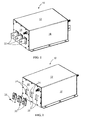
FIG. 1 is a perspective view of an illustrative assembly in which a bus bar insulator is inserted; -
FIG. 2 is a perspective view of a front wall of the assembly ofFIG. 1 , showing three bus bar insulators exploded from openings of the front wall of the assembly, the fasteners being enlarged for purposes of clarity; -
FIG. 3 is a front view of an illustrative bus bar insulator of the type shown inFIG. 1 ; -
FIG. 4 is a rear view of the illustrative bus bar insulator ofFIG. 3 ; -
FIG. 5 is a cross-sectional view of the illustrative bus bar insulator taken along line 5-5 ofFIG. 3 ; -
FIG. 6 is a partial perspective view of a bus bar as positioned in an opening of the assembly ofFIG. 2 ; and -
FIG. 7 is a front view of an alternate illustrative bus bar insulator. - Wherever possible, the same reference numbers will be used throughout the drawings to refer to the same or like parts.
- It is an object of this invention to obviate the above-described problems.
- It is another object of this invention to provide a supporting insulator which minimizes the distance necessary between and beyond adjacent insulators while assuring that the required spacing between conductors of opposite polarity is provided.
- It is another object of this invention to provide an insulator which includes features to restrict axial motion of the bus bar.
- According to an embodiment, an insulator for electrically isolating the walls of an assembly and bus bars which extend through the assembly is provided. The insulator includes a mounting member having contoured edges. A bus bar-holding opening extends through the mounting member. Mounting openings are provided on the mounting member. The mounting openings being dimensioned to receive mounting hardware therein. The mounting openings are offset from the geometrical centerline of the bus bar-holding opening by more than the radius of the mounting hardware. The mounting hardware of adjacent insulators may be thereby interleaved to allow for close placement of the insulators while maintaining required spacing to provide proper electrical isolation.
- According to an alternate embodiment, an assembly through which at least one bus bar extends is disclosed. The assembly includes a first mounting panel on one end and an oppositely facing second mounting panel on the opposite end, the first and second mounting panel having bus bar-receiving openings which extend therethrough. An insulator is positioned in each of the bus bar-receiving openings. Each insulator includes a contoured mounting member. A bus bar-holding opening extends through the mounting member. Axial engagement members are on the insulator. The axial engagement members cooperate with the at least one bus bar to restrict the axial movement of the at least one bus bar.
- According to an alternate embodiment, an assembly through which at least one bus bar extends is disclosed. The assembly includes a first mounting panel on one end and an oppositely facing second mounting panel; with the first and second mounting panels having bus bar-receiving openings which extend therethrough. Insulators are positioned in each of the bus bar-receiving openings. Each insulator includes a mounting member, mounting openings, bus bar holding openings, and bus bar-engagement members. The mounting member having contoured edges. The mounting openings are offset from the geometrical centerline of the bus bar-holding opening by more than the radius of mounting hardware used to mount the insulator to a respective mounting panel of the assembly. The bus bar-holding opening extends through the mounting member. The bus bar engagement members are provided on the insulator proximate the bus bar receiving opening. The bus bar-engagement members are dimensioned to receive insulator engagement members provided on the at least one bus bar which is positioned in the bus bar-holding opening. The mounting hardware of adjacent insulators are interleaved to allow for close spacing of the insulators while maintaining proper spacing to provide the electrical insulation required for the at least one bus bar.
- The present invention will be described more fully hereinafter with reference to the accompanying drawings, in which illustrative embodiments of the invention are shown. In the drawings, the relative sizes of regions or features may be exaggerated for clarity. This invention may, however, be embodied in many different forms and should not be construed as limited to the embodiments set forth herein; rather, these embodiments are provided so that this disclosure will be thorough and complete, and will fully convey the scope of the invention to those skilled in the art.
- It will be understood that spatially relative terms, such as "top", "upper", "lower" and the like, may be used herein for ease of description to describe one element's or feature's relationship to another element(s) or feature(s) as illustrated in the figures. It will be understood that the spatially relative terms are intended to encompass different orientations of the device in use or operation in addition to the orientation depicted in the figures. For example, if the device in the figures is turned over, elements described as "over" other elements or features would then be oriented "under" the other elements or features. Thus, the exemplary term "over" can encompass both an orientation of over and under. The device may be otherwise oriented (rotated 90 degrees or at other orientations) and the spatially relative descriptors used herein interpreted accordingly.
- The present invention is directed to an insulator for use with bus bars and the like, the insulator minimizes the distance necessary between and beyond adjacent insulators to assure the required spacing between conductors of opposite polarity, such as, but not limited to, adjacent bus bars, the insulator fasteners and the conductive panel. Additionally, the insulator includes features to engage features on or in the bus bar to restrict axial motion of the bus bar.
- Referring to
FIGS. 1 and 2 , anillustrative assembly 10 is illustrated. Theassembly 10 may be any device through which bus bars or the like are provided. Such assemblies include, but are not limited to filters, switches and the like. - The
assembly 10 has atop wall 12, a bottom wall (not shown) andside walls 16 which extend between thetop wall 12 and the bottom wall. A front wall or mountingpanel 18 and a back wall or mounting panel (not shown) extend between thetop wall 12 and the bottom wall and extend between theside walls 16. Asfront wall 18 and back wall are essentially similar, onlyfront wall 18 will be described in more detail. However, the description of thefront wall 18 is equally applicable to the back wall. The walls are made from electrically conductive material to provide shielding to the components used in theassembly 10, as is known in the industry. - Contained inside the
assembly 10 are the various components need for proper operation of the assembly. For example, if theassembly 10 is a filter, capacitors, resistors and the like are provided in the interior of theassembly 10. - As best shown in
FIG. 2 , bus bar-receivingopenings 20 extend throughfront wall 18. In the illustrative embodiment shown, threeopenings 20 are shown, but any number can be provided without departing from the scope of the invention. Theopenings 20 are dimensioned to receiveinsulators 30 and bus bars 22 (FIG. 1 ) therethrough.Fastener receiving openings 24 are offset from the geometrical centerline of thebus bar 22 by more than the radius r of afastener 26 which is received in arespective opening 24, as will be more fully described below. In the embodiment shown, theopenings 24 are located in diagonally opposite corners relative to theopenings 20. - Referring to
FIGS. 3 through 5 , aninsulator 30 is shown. Theinsulator 30 has a contoured mounting plate ormember 32 with afirst surface 34 and an oppositely facingsecond surface 36.Side walls 38 and endwalls 40 form a contoured edge which extends between thefirst surface 34 and thesecond surface 36. In the illustrative embodiment shown, theside walls 38 extend in a direction which is essentially parallel to each other and theend walls 40 extend from theside walls 38 at an angle other than 90 degrees. Theend walls 40 also extend in a direction which is essentially parallel each other. While the side walls and end walls are described with respect to the embodiment shown, the mountingmember 32 may have any type of contoured edge with any arbitrary shape so long as the mountingmember 32 interleaves diagonally with adjacent mountingmembers 32. In various embodiments, the mountingmember 32 has two fold rotational symmetry, including substantially straight sides that are non-perpendicular to a line which extends through the rotational center of the mountingmember 32. Alternatively, in other embodiments, the mountingmember 32 has two fold rotational symmetry, including substantially straight sides that are perpendicular to the line through the rotational center that connects them. - A bus
bar holding opening 44 extends through the mountingmember 32. Theopening 44 is dimensioned to be smaller than arespective opening 20. - In the embodiment shown in
FIG. 3 , mountingflanges 46 are provided on the mountingmember 32. The mounting flanges extend from proximate theopening 44 toward the intersection of arespective side wall 38 and arespective end wall 40. Theflanges 46 are located or formed in diagonally opposite corners of the mountingmember 32. Mountingopenings 48 are provided in each mountingflange 46. Theopenings 48 are dimensioned to receive the mounting hardware orfasteners 26, such as, but not limited to, rivets or screws therein. Theopenings 48 are offset from the geometrical centerline of theopening 44 or the bus bar by more than the radius r of therespective fastener 26 positioned in theopenings 48. Theopenings 48 align withopenings 24 to allow thefasteners 26 to be properly mounted throughopenings 48 and intoopenings 24 to secure theinsulator 30 to the respective front or back wall of theassembly 10. However, other embodiments may be used without departing from the invention. In general, the mountingflanges 46 are areas of the mountingmembers 32 which are intended to receive and supportfasteners 26. The mountingflanges 46 need not be tangent with adjoining edges of the mountingmembers 32 nor geometrically distinct.FIG. 7 illustrates an alternate embodiment of the mountingflanges 46 and mountingmember 32. - As best shown in
FIGS. 4 and 5 , axial engagement members or bus bar engagement members, such as, but not limited to, cutouts or recesses 52 are providedproximate openings 44. Therecesses 52 are dimensioned to receive insulator engagement members, such as, but not limited to,projections 54 provided on the bus bars 22. In the illustrative embodiment shown, theprojections 54 of the bus bars 22 engage asurface 56 of therecesses 52 to restrict axial motion of the bus bars 22 in one direction. Such engagement may be accomplished by, but is not limited to, frictional engagement or adhesive-bonding. The use ofsuch insulators 30, which restrict axial motion in one direction, on opposite ends of theassembly 10 completely restrain the bus bars 22 and prevents axial movement of the bus bars 22 relative to theassembly 10. While the illustrative embodiment shows recesses 52 on theinsulators 30 and aprojection 54 on the bus bars 22, other configuration can be used without departing from the scope of the invention. For example, theinsulator 30 may include pockets or protrusions to capture, partially capture or cooperate with a feature developed or inserted into the bus bars 22, such as, but not limited to a recess, thereby restraining axial motion of the bus bars 22 in at least one direction relative to theinsulator 30 and theassembly 10. Additionally, the bus bar engagement member and/or the insulator engagement members may be independent components which are cooperate with the bus bars 22 to restrict axial motion of the bus bars 22. - As shown in
FIG. 5 , in one embodiment an insulating sleeve orprojection 60 having insulatingwalls 62 may extend from thesecond surface 36 of the mountingmember 32 of eachinsulator 30 in a direction away from thefirst surface 34. Alternatively, or additionally, the insulatingprojection 60 may extend from thefirst surface 34 in a direction away from thesecond surface 36. Theopening 44 extends from the mounting ormating member 32 through the insulatingprojection 60. The insulating walls orsleeves 62 have a length sufficient to extend beyond the thickness of the front or back wall of theassembly 10, thereby providing sufficient insulation between the walls of theassembly 10 and the bus bars 22 which extend through theopenings 44. In various embodiments, the insulatingprojection 60 is not required and may be omitted. - During assembly of the
assembly 10, the bus bars 22 are positioned and attached to respective components (not shown). The walls of theassembly 10 are moved into position and secured. As the front wall or mounting panel and/or back wall or mounting panel are moved into position, the ends of the bus bars 22 are inserted throughrespective openings 20. With the bus bars 22 properly positioned in theopening 20, theinsulators 30 are inserted on the ends of the bus bars 22, such that the ends of the bus bars 22 are positioned inopenings 44. Insertion of each of theinsulators 30 continues until thesecond surface 36 of the mountingmember 32 engages a respective mounting panel of the assembly proximate theopening 20. In this position, the insulating walls orsleeves 62 may be inserted throughopening 20, thereby electrically and physically separatingbus bars 22 from the mounting panel of theassembly 10. -
Fasteners 26 are inserted throughopenings 48 of the mountingflange 46 of the mountingmember 32 and intoopenings 24 of the front or back mounting panel to properly secure theinsulator 30 to the respective mounting panel. - Alternatively, the insulators may be positioned on the bus bars 22 prior to some or all of the walls of the
assembly 10 being moved into position and secured. In this embodiment, theinsulators 30 are captured between thefront panel 18 and the back panel. With the bus bars 22 properly positioned in theopening 20, theinsulators 30 are moved such that thesecond surfaces 36 of the mountingmembers 32 engage a respective mounting panel of the assembly proximate theopening 20. In this position, the insulating walls orsleeves 62 may be inserted throughopening 20, thereby electrically and physically separatingbus bars 22 from the mounting panel of theassembly 10.Fasteners 26 are inserted throughopenings 24 of the front or back mounting panel intoopenings 48 of the mountingflange 46 of the mountingmember 32 to properly secure theinsulator 30 to the respective mounting panel. Other methods of inserting the fasteners can be used without departing from the scope of the invention. - As previously stated, the mounting
openings 48 are offset from the geometrical centerline of theopening 44 and/or the geometric centerline of thebus bar 22 positioned in the opening by more than the radius r of thefastener 26. This geometry allows the fastener locations to interleave transversely in the direction of anadjacent insulator 30, while remaining sufficiently distant from thebus bar 22 supported by theadjacent insulator 30. This allows for the close placement ofadjacent insulators 30 andbus bars 22, providing appropriate electrical insulation between the bus bars 22 and theassembly 10, while limiting the amount of space required for theinsulators 30 and its mounting hardware orfasteners 26. In application in which the size of all components must be minimized, the configuration of theinsulator 30 described herein is advantageous. - With each
insulator 30 properly mounted, the axial engagement members or surface 56 of theinsulator 30 is provided proximate to or in engagement with theprojections 54 of thebus bar 22. The cooperation of thesurface 56 with theprojection 54 prohibits theprojection 54 from moving beyond thesurface 56, thereby restraining axial motion of thebus bar 22 in at least one direction. Use ofsuch insulators 30 on opposite ends of theassembly 10 completely restrains or limits thebus bar 22 from movement relative to theassembly 10 in the axial direction of the bus bar. - The mounting
member 32 and the insulating sleeve orprojection 60 are optionally relieved to improve manufacturability by injection molding, while preserving strength and aesthetics, and reducing material usage.
Claims (9)
- An insulator (30) for providing insulation between walls (18) of an assembly (10) and a bus bar (22) which extend through the assembly, the insulator comprising:a contoured mounting member (32) having a contoured edge (38, 40);a bus bar-holding opening (44) extending through the mounting member (32); andmounting openings (48) provided on the mounting member (32), the mounting openings (48) being dimensioned to receive mounting hardware (26) therein, and the mounting openings (48) being offset from the geometrical centerline of the bus bar-holding opening (44) by more than the radius (r) of the mounting hardware (26).
- The insulator as recited in claim 1, wherein the contoured mounting member (32) has twofold rotational symmetry with at least one respective mounting opening (48) provided proximate a first edge (38) of the contoured mounting member (32) and at least one respective mounting opening (48) provide proximate a second edge (40) of the contoured mounting member (32).
- The insulator as recited in claim 1 or 2, wherein axial engagement members (52) are provided on the insulator (30), the axial engagement members (52) arranged to cooperate with the bus bar (22) to restrict the axial motion of the bus bar (22) relative to the insulator (30).
- The insulator as recited in claim 3, wherein the axial engagement members of the insulator (30) are recesses (52) which are arranged to engage interlocking components (54) of the bus bar (22).
- The insulator as recited in claim 3, wherein the axial engagement members of the insulator (30) are projections which are arranged to engage recesses of the bus bar (22).
- The insulator as recited in claim 3, 4 or 5, wherein the axial engagement members are provided on an insulating projection which extends from a surface (36) of the mounting member (32).
- The insulator as recited in any one of claims 1 to 5, wherein an insulating projection (60) has a first insulating wall or walls (62) extending from a second surface (36) of the mounting member (32), the bus bar-holding opening (44) extending from the mounting member (32) through the insulating projection (60).
- The insulator as recited in claim 7, wherein a second insulating wall or walls of the insulating projection (60) extend from a first surface (34) of the mounting member (32) in a direction away from the first insulating wall or walls (62).
- The insulator as recited in any preceding claim, wherein mounting flanges (46) extend from proximate the bus bar-holding opening (44), the flanges (46) formed in opposite corners of the mounting member (32), the mounting openings (48) provided in each mounting flange (46).
Applications Claiming Priority (1)
| Application Number | Priority Date | Filing Date | Title |
|---|---|---|---|
| US13/742,399 US9269474B2 (en) | 2013-01-16 | 2013-01-16 | Bus bar insulator |
Publications (2)
| Publication Number | Publication Date |
|---|---|
| EP2757644A1 true EP2757644A1 (en) | 2014-07-23 |
| EP2757644B1 EP2757644B1 (en) | 2018-03-28 |
Family
ID=49955209
Family Applications (1)
| Application Number | Title | Priority Date | Filing Date |
|---|---|---|---|
| EP14151335.8A Active EP2757644B1 (en) | 2013-01-16 | 2014-01-15 | Bus bar insulator |
Country Status (3)
| Country | Link |
|---|---|
| US (1) | US9269474B2 (en) |
| EP (1) | EP2757644B1 (en) |
| CN (1) | CN103928804B (en) |
Families Citing this family (3)
| Publication number | Priority date | Publication date | Assignee | Title |
|---|---|---|---|---|
| USD972199S1 (en) * | 2019-12-02 | 2022-12-06 | Ekamdeep Singh | Lighting structure |
| US11910495B2 (en) * | 2019-12-13 | 2024-02-20 | Goodrich Corporation | Conductive ink with enhanced mechanical fatigue resistance |
| US12469622B2 (en) * | 2022-09-28 | 2025-11-11 | Rockwell Automation Technologies, Inc. | Insulating holder for multi-phase bus bar |
Citations (4)
| Publication number | Priority date | Publication date | Assignee | Title |
|---|---|---|---|---|
| GB586477A (en) * | 1944-03-18 | 1947-03-20 | Brookhirst Switchgear Ltd | Improvements in or relating to bushes or the like |
| FR2633439A1 (en) * | 1988-06-22 | 1989-12-29 | Alsthom | BARRIER FOR ELECTRICAL TRANSFORMER |
| US20020023769A1 (en) * | 1998-03-18 | 2002-02-28 | Olivier Pioch | Busbar bushing device and bar lead-in |
| DE102008023879A1 (en) * | 2008-05-16 | 2009-11-19 | Wöhner GmbH & Co. KG Elektrotechnische Systeme | Fastening module for front-sided fastening of bus bar at cross bar in switching cabinet, has breadboards for inserting fastener lateral to T-shaped retaining groove, where breadboards have holes with tangents running diagonal to module axis |
Family Cites Families (20)
| Publication number | Priority date | Publication date | Assignee | Title |
|---|---|---|---|---|
| US1813200A (en) * | 1928-06-27 | 1931-07-07 | Carey Philip Mfg Co | Cover for third rail and other electric conductors |
| US4022967A (en) * | 1975-11-28 | 1977-05-10 | Midland-Ross Corporation | Clamping holder for busbars |
| US4129354A (en) * | 1977-08-01 | 1978-12-12 | General Signal Corporation | Bus bar clamp |
| US4737745A (en) | 1986-11-03 | 1988-04-12 | Westinghouse Electric Corp. | Electromagnetic interference filter assembly |
| CA1296416C (en) * | 1987-11-30 | 1992-02-25 | Robert A. Wilson | Busbar arrangement for a switchgear assembly |
| DE3811457A1 (en) * | 1988-04-06 | 1989-10-19 | Loh Kg Rittal Werk | BUSBAR SYSTEM WITH BRACKETS AND POWER BUSBAR SECTIONS |
| US5181165A (en) * | 1991-10-24 | 1993-01-19 | Westinghouse Electric Corp. | Panelboard with insulative snap-in support means |
| US5211585A (en) * | 1992-02-28 | 1993-05-18 | Amp Incorporated | Electrical connector housings having polarizing means |
| US5213518A (en) * | 1992-02-28 | 1993-05-25 | Amp Incorporated | Connecting electrical bus bars to electrical circuitry |
| JP3493935B2 (en) * | 1997-02-25 | 2004-02-03 | 松下電器産業株式会社 | Bushing |
| DE19712363C1 (en) * | 1997-03-25 | 1998-06-10 | Loh Kg Rittal Werk | Bus=bars retainer for bus=bar system |
| US6218913B1 (en) | 1998-02-18 | 2001-04-17 | Curtis Industries, A Division Of Powers Holatings, Inc. | Coaxial toroid EMI filter with discrete capacitors surrounding conductors |
| FR2819678B1 (en) | 2001-01-12 | 2003-04-11 | Sagem | FILTERING CIRCUIT, AND POWER SUPPLY DEVICE PROVIDED WITH SUCH A FILTERING CIRCUIT |
| US6781818B2 (en) * | 2002-11-22 | 2004-08-24 | Siemens Energy & Automation | Bus brace comb assembly |
| DE102005013509C5 (en) | 2004-03-30 | 2024-08-29 | Schaffner Emv Ag | EMC Filter |
| CA2644833A1 (en) * | 2006-03-06 | 2007-09-13 | Siemens Energy & Automation, Inc. | Bus joint assembly |
| US7399194B1 (en) * | 2007-05-10 | 2008-07-15 | Charles David Gilliam | Electric connector |
| CN201247657Y (en) * | 2008-07-25 | 2009-05-27 | 河南索凌电气有限公司 | High voltage insulating sleeve |
| US7854636B2 (en) * | 2009-01-07 | 2010-12-21 | Charles David Gilliam | High power, single pole electrical connector |
| CN202405716U (en) * | 2012-01-18 | 2012-08-29 | 中骏电气(厦门)有限公司 | Copper bar supporting and fixing device |
-
2013
- 2013-01-16 US US13/742,399 patent/US9269474B2/en active Active
-
2014
- 2014-01-15 EP EP14151335.8A patent/EP2757644B1/en active Active
- 2014-01-16 CN CN201410122463.5A patent/CN103928804B/en active Active
Patent Citations (4)
| Publication number | Priority date | Publication date | Assignee | Title |
|---|---|---|---|---|
| GB586477A (en) * | 1944-03-18 | 1947-03-20 | Brookhirst Switchgear Ltd | Improvements in or relating to bushes or the like |
| FR2633439A1 (en) * | 1988-06-22 | 1989-12-29 | Alsthom | BARRIER FOR ELECTRICAL TRANSFORMER |
| US20020023769A1 (en) * | 1998-03-18 | 2002-02-28 | Olivier Pioch | Busbar bushing device and bar lead-in |
| DE102008023879A1 (en) * | 2008-05-16 | 2009-11-19 | Wöhner GmbH & Co. KG Elektrotechnische Systeme | Fastening module for front-sided fastening of bus bar at cross bar in switching cabinet, has breadboards for inserting fastener lateral to T-shaped retaining groove, where breadboards have holes with tangents running diagonal to module axis |
Also Published As
| Publication number | Publication date |
|---|---|
| EP2757644B1 (en) | 2018-03-28 |
| CN103928804A (en) | 2014-07-16 |
| US9269474B2 (en) | 2016-02-23 |
| CN103928804B (en) | 2017-08-04 |
| US20140196927A1 (en) | 2014-07-17 |
Similar Documents
| Publication | Publication Date | Title |
|---|---|---|
| EP2484189B1 (en) | Tool-less installation system and method of u-mounted devices | |
| RU2699232C1 (en) | Device for touch-protected contact with system of current-conducting buses | |
| EP2908388A1 (en) | Tool-less busway take-off device for electrical busway and method of installing | |
| US10030689B2 (en) | Mounting system for mounting of equipment in particular electrical appliances | |
| EP2757644B1 (en) | Bus bar insulator | |
| CN110277278B (en) | Socket with improved structure | |
| EP3454436B1 (en) | Compartment-partitioning and busbar-supporting device in a cabinet for a low voltage electrical switchboard | |
| CN105981227B (en) | Terminal block | |
| MX2013014621A (en) | Methods of assembling a neutral rail to a plug-on neutral load center. | |
| EP3270465A1 (en) | Socket | |
| CA2081286C (en) | Panelboard with insulative snap-in support means | |
| EP3053230B1 (en) | Snap-in shutter system for rack out circuit breakers | |
| CA2900931A1 (en) | Adapter system for plug-on neutral load center | |
| EP3054537A1 (en) | Electrical connector allowing disassembly, electronic module, and assembly method | |
| EP2704545A2 (en) | Electronic device, manufacturing method and connection method | |
| US8801442B2 (en) | Device for positioning at least one multiple round plug | |
| CN105264729A (en) | Modular holder for electric conductors | |
| CN107710504B (en) | Vertically oriented electronic device, method of constructing and method of constructing a subassembly | |
| KR101829347B1 (en) | Busbar assembly | |
| EP3293842A1 (en) | Frame for mounting electrical apparatus | |
| CN107454814B (en) | Electric shell | |
| CN211376698U (en) | Battery pack for vehicle and vehicle | |
| CN107534803B (en) | Antenna mounted in electronic device | |
| KR20170002387U (en) | Joint block | |
| EP2988051A1 (en) | Multifunctional fixture apparatus and assembly thereof |
Legal Events
| Date | Code | Title | Description |
|---|---|---|---|
| PUAI | Public reference made under article 153(3) epc to a published international application that has entered the european phase |
Free format text: ORIGINAL CODE: 0009012 |
|
| 17P | Request for examination filed |
Effective date: 20140115 |
|
| AK | Designated contracting states |
Kind code of ref document: A1 Designated state(s): AL AT BE BG CH CY CZ DE DK EE ES FI FR GB GR HR HU IE IS IT LI LT LU LV MC MK MT NL NO PL PT RO RS SE SI SK SM TR |
|
| AX | Request for extension of the european patent |
Extension state: BA ME |
|
| R17P | Request for examination filed (corrected) |
Effective date: 20150121 |
|
| RBV | Designated contracting states (corrected) |
Designated state(s): AL AT BE BG CH CY CZ DE DK EE ES FI FR GB GR HR HU IE IS IT LI LT LU LV MC MK MT NL NO PL PT RO RS SE SI SK SM TR |
|
| RAP1 | Party data changed (applicant data changed or rights of an application transferred) |
Owner name: TE CONNECTIVITY CORPORATION |
|
| GRAP | Despatch of communication of intention to grant a patent |
Free format text: ORIGINAL CODE: EPIDOSNIGR1 |
|
| STAA | Information on the status of an ep patent application or granted ep patent |
Free format text: STATUS: GRANT OF PATENT IS INTENDED |
|
| INTG | Intention to grant announced |
Effective date: 20171130 |
|
| RIN1 | Information on inventor provided before grant (corrected) |
Inventor name: CRAIG, EVAN LAWRENCE |
|
| GRAS | Grant fee paid |
Free format text: ORIGINAL CODE: EPIDOSNIGR3 |
|
| GRAA | (expected) grant |
Free format text: ORIGINAL CODE: 0009210 |
|
| STAA | Information on the status of an ep patent application or granted ep patent |
Free format text: STATUS: THE PATENT HAS BEEN GRANTED |
|
| AK | Designated contracting states |
Kind code of ref document: B1 Designated state(s): AL AT BE BG CH CY CZ DE DK EE ES FI FR GB GR HR HU IE IS IT LI LT LU LV MC MK MT NL NO PL PT RO RS SE SI SK SM TR |
|
| REG | Reference to a national code |
Ref country code: GB Ref legal event code: FG4D |
|
| REG | Reference to a national code |
Ref country code: CH Ref legal event code: EP |
|
| REG | Reference to a national code |
Ref country code: AT Ref legal event code: REF Ref document number: 984226 Country of ref document: AT Kind code of ref document: T Effective date: 20180415 |
|
| REG | Reference to a national code |
Ref country code: IE Ref legal event code: FG4D |
|
| REG | Reference to a national code |
Ref country code: DE Ref legal event code: R096 Ref document number: 602014022870 Country of ref document: DE |
|
| PG25 | Lapsed in a contracting state [announced via postgrant information from national office to epo] |
Ref country code: NO Free format text: LAPSE BECAUSE OF FAILURE TO SUBMIT A TRANSLATION OF THE DESCRIPTION OR TO PAY THE FEE WITHIN THE PRESCRIBED TIME-LIMIT Effective date: 20180628 Ref country code: LT Free format text: LAPSE BECAUSE OF FAILURE TO SUBMIT A TRANSLATION OF THE DESCRIPTION OR TO PAY THE FEE WITHIN THE PRESCRIBED TIME-LIMIT Effective date: 20180328 Ref country code: HR Free format text: LAPSE BECAUSE OF FAILURE TO SUBMIT A TRANSLATION OF THE DESCRIPTION OR TO PAY THE FEE WITHIN THE PRESCRIBED TIME-LIMIT Effective date: 20180328 Ref country code: FI Free format text: LAPSE BECAUSE OF FAILURE TO SUBMIT A TRANSLATION OF THE DESCRIPTION OR TO PAY THE FEE WITHIN THE PRESCRIBED TIME-LIMIT Effective date: 20180328 |
|
| REG | Reference to a national code |
Ref country code: NL Ref legal event code: MP Effective date: 20180328 |
|
| REG | Reference to a national code |
Ref country code: LT Ref legal event code: MG4D |
|
| PG25 | Lapsed in a contracting state [announced via postgrant information from national office to epo] |
Ref country code: GR Free format text: LAPSE BECAUSE OF FAILURE TO SUBMIT A TRANSLATION OF THE DESCRIPTION OR TO PAY THE FEE WITHIN THE PRESCRIBED TIME-LIMIT Effective date: 20180629 Ref country code: BG Free format text: LAPSE BECAUSE OF FAILURE TO SUBMIT A TRANSLATION OF THE DESCRIPTION OR TO PAY THE FEE WITHIN THE PRESCRIBED TIME-LIMIT Effective date: 20180628 Ref country code: RS Free format text: LAPSE BECAUSE OF FAILURE TO SUBMIT A TRANSLATION OF THE DESCRIPTION OR TO PAY THE FEE WITHIN THE PRESCRIBED TIME-LIMIT Effective date: 20180328 Ref country code: SE Free format text: LAPSE BECAUSE OF FAILURE TO SUBMIT A TRANSLATION OF THE DESCRIPTION OR TO PAY THE FEE WITHIN THE PRESCRIBED TIME-LIMIT Effective date: 20180328 Ref country code: LV Free format text: LAPSE BECAUSE OF FAILURE TO SUBMIT A TRANSLATION OF THE DESCRIPTION OR TO PAY THE FEE WITHIN THE PRESCRIBED TIME-LIMIT Effective date: 20180328 |
|
| PG25 | Lapsed in a contracting state [announced via postgrant information from national office to epo] |
Ref country code: PL Free format text: LAPSE BECAUSE OF FAILURE TO SUBMIT A TRANSLATION OF THE DESCRIPTION OR TO PAY THE FEE WITHIN THE PRESCRIBED TIME-LIMIT Effective date: 20180328 Ref country code: NL Free format text: LAPSE BECAUSE OF FAILURE TO SUBMIT A TRANSLATION OF THE DESCRIPTION OR TO PAY THE FEE WITHIN THE PRESCRIBED TIME-LIMIT Effective date: 20180328 Ref country code: ES Free format text: LAPSE BECAUSE OF FAILURE TO SUBMIT A TRANSLATION OF THE DESCRIPTION OR TO PAY THE FEE WITHIN THE PRESCRIBED TIME-LIMIT Effective date: 20180328 Ref country code: AL Free format text: LAPSE BECAUSE OF FAILURE TO SUBMIT A TRANSLATION OF THE DESCRIPTION OR TO PAY THE FEE WITHIN THE PRESCRIBED TIME-LIMIT Effective date: 20180328 Ref country code: RO Free format text: LAPSE BECAUSE OF FAILURE TO SUBMIT A TRANSLATION OF THE DESCRIPTION OR TO PAY THE FEE WITHIN THE PRESCRIBED TIME-LIMIT Effective date: 20180328 Ref country code: EE Free format text: LAPSE BECAUSE OF FAILURE TO SUBMIT A TRANSLATION OF THE DESCRIPTION OR TO PAY THE FEE WITHIN THE PRESCRIBED TIME-LIMIT Effective date: 20180328 |
|
| PG25 | Lapsed in a contracting state [announced via postgrant information from national office to epo] |
Ref country code: CZ Free format text: LAPSE BECAUSE OF FAILURE TO SUBMIT A TRANSLATION OF THE DESCRIPTION OR TO PAY THE FEE WITHIN THE PRESCRIBED TIME-LIMIT Effective date: 20180328 Ref country code: SM Free format text: LAPSE BECAUSE OF FAILURE TO SUBMIT A TRANSLATION OF THE DESCRIPTION OR TO PAY THE FEE WITHIN THE PRESCRIBED TIME-LIMIT Effective date: 20180328 Ref country code: SK Free format text: LAPSE BECAUSE OF FAILURE TO SUBMIT A TRANSLATION OF THE DESCRIPTION OR TO PAY THE FEE WITHIN THE PRESCRIBED TIME-LIMIT Effective date: 20180328 |
|
| REG | Reference to a national code |
Ref country code: AT Ref legal event code: MK05 Ref document number: 984226 Country of ref document: AT Kind code of ref document: T Effective date: 20180328 |
|
| PG25 | Lapsed in a contracting state [announced via postgrant information from national office to epo] |
Ref country code: PT Free format text: LAPSE BECAUSE OF FAILURE TO SUBMIT A TRANSLATION OF THE DESCRIPTION OR TO PAY THE FEE WITHIN THE PRESCRIBED TIME-LIMIT Effective date: 20180730 |
|
| REG | Reference to a national code |
Ref country code: DE Ref legal event code: R097 Ref document number: 602014022870 Country of ref document: DE |
|
| PG25 | Lapsed in a contracting state [announced via postgrant information from national office to epo] |
Ref country code: AT Free format text: LAPSE BECAUSE OF FAILURE TO SUBMIT A TRANSLATION OF THE DESCRIPTION OR TO PAY THE FEE WITHIN THE PRESCRIBED TIME-LIMIT Effective date: 20180328 Ref country code: DK Free format text: LAPSE BECAUSE OF FAILURE TO SUBMIT A TRANSLATION OF THE DESCRIPTION OR TO PAY THE FEE WITHIN THE PRESCRIBED TIME-LIMIT Effective date: 20180328 |
|
| PLBE | No opposition filed within time limit |
Free format text: ORIGINAL CODE: 0009261 |
|
| STAA | Information on the status of an ep patent application or granted ep patent |
Free format text: STATUS: NO OPPOSITION FILED WITHIN TIME LIMIT |
|
| PG25 | Lapsed in a contracting state [announced via postgrant information from national office to epo] |
Ref country code: IT Free format text: LAPSE BECAUSE OF FAILURE TO SUBMIT A TRANSLATION OF THE DESCRIPTION OR TO PAY THE FEE WITHIN THE PRESCRIBED TIME-LIMIT Effective date: 20180328 |
|
| 26N | No opposition filed |
Effective date: 20190103 |
|
| PG25 | Lapsed in a contracting state [announced via postgrant information from national office to epo] |
Ref country code: SI Free format text: LAPSE BECAUSE OF FAILURE TO SUBMIT A TRANSLATION OF THE DESCRIPTION OR TO PAY THE FEE WITHIN THE PRESCRIBED TIME-LIMIT Effective date: 20180328 |
|
| PG25 | Lapsed in a contracting state [announced via postgrant information from national office to epo] |
Ref country code: MC Free format text: LAPSE BECAUSE OF FAILURE TO SUBMIT A TRANSLATION OF THE DESCRIPTION OR TO PAY THE FEE WITHIN THE PRESCRIBED TIME-LIMIT Effective date: 20180328 |
|
| REG | Reference to a national code |
Ref country code: CH Ref legal event code: PL |
|
| PG25 | Lapsed in a contracting state [announced via postgrant information from national office to epo] |
Ref country code: LU Free format text: LAPSE BECAUSE OF NON-PAYMENT OF DUE FEES Effective date: 20190115 |
|
| REG | Reference to a national code |
Ref country code: BE Ref legal event code: MM Effective date: 20190131 |
|
| REG | Reference to a national code |
Ref country code: IE Ref legal event code: MM4A |
|
| PG25 | Lapsed in a contracting state [announced via postgrant information from national office to epo] |
Ref country code: BE Free format text: LAPSE BECAUSE OF NON-PAYMENT OF DUE FEES Effective date: 20190131 |
|
| PG25 | Lapsed in a contracting state [announced via postgrant information from national office to epo] |
Ref country code: CH Free format text: LAPSE BECAUSE OF NON-PAYMENT OF DUE FEES Effective date: 20190131 Ref country code: LI Free format text: LAPSE BECAUSE OF NON-PAYMENT OF DUE FEES Effective date: 20190131 |
|
| PG25 | Lapsed in a contracting state [announced via postgrant information from national office to epo] |
Ref country code: IE Free format text: LAPSE BECAUSE OF NON-PAYMENT OF DUE FEES Effective date: 20190115 |
|
| PGFP | Annual fee paid to national office [announced via postgrant information from national office to epo] |
Ref country code: FR Payment date: 20191216 Year of fee payment: 7 |
|
| PG25 | Lapsed in a contracting state [announced via postgrant information from national office to epo] |
Ref country code: TR Free format text: LAPSE BECAUSE OF FAILURE TO SUBMIT A TRANSLATION OF THE DESCRIPTION OR TO PAY THE FEE WITHIN THE PRESCRIBED TIME-LIMIT Effective date: 20180328 |
|
| PG25 | Lapsed in a contracting state [announced via postgrant information from national office to epo] |
Ref country code: MT Free format text: LAPSE BECAUSE OF NON-PAYMENT OF DUE FEES Effective date: 20190115 |
|
| PG25 | Lapsed in a contracting state [announced via postgrant information from national office to epo] |
Ref country code: CY Free format text: LAPSE BECAUSE OF FAILURE TO SUBMIT A TRANSLATION OF THE DESCRIPTION OR TO PAY THE FEE WITHIN THE PRESCRIBED TIME-LIMIT Effective date: 20180328 |
|
| PG25 | Lapsed in a contracting state [announced via postgrant information from national office to epo] |
Ref country code: IS Free format text: LAPSE BECAUSE OF FAILURE TO SUBMIT A TRANSLATION OF THE DESCRIPTION OR TO PAY THE FEE WITHIN THE PRESCRIBED TIME-LIMIT Effective date: 20180728 |
|
| PG25 | Lapsed in a contracting state [announced via postgrant information from national office to epo] |
Ref country code: HU Free format text: LAPSE BECAUSE OF FAILURE TO SUBMIT A TRANSLATION OF THE DESCRIPTION OR TO PAY THE FEE WITHIN THE PRESCRIBED TIME-LIMIT; INVALID AB INITIO Effective date: 20140115 |
|
| PG25 | Lapsed in a contracting state [announced via postgrant information from national office to epo] |
Ref country code: FR Free format text: LAPSE BECAUSE OF NON-PAYMENT OF DUE FEES Effective date: 20210131 |
|
| PG25 | Lapsed in a contracting state [announced via postgrant information from national office to epo] |
Ref country code: MK Free format text: LAPSE BECAUSE OF FAILURE TO SUBMIT A TRANSLATION OF THE DESCRIPTION OR TO PAY THE FEE WITHIN THE PRESCRIBED TIME-LIMIT Effective date: 20180328 |
|
| REG | Reference to a national code |
Ref country code: GB Ref legal event code: 732E Free format text: REGISTERED BETWEEN 20250731 AND 20250806 |
|
| PGFP | Annual fee paid to national office [announced via postgrant information from national office to epo] |
Ref country code: GB Payment date: 20251204 Year of fee payment: 13 |
|
| PGFP | Annual fee paid to national office [announced via postgrant information from national office to epo] |
Ref country code: DE Payment date: 20251203 Year of fee payment: 13 |