EP2757413A1 - Reflective dimming electrochromic element inserted with non-water based hydrogen ion conductive electrolyte layer, and dimming element using said reflective dimming electrochromic element - Google Patents
Reflective dimming electrochromic element inserted with non-water based hydrogen ion conductive electrolyte layer, and dimming element using said reflective dimming electrochromic element Download PDFInfo
- Publication number
- EP2757413A1 EP2757413A1 EP20120831574 EP12831574A EP2757413A1 EP 2757413 A1 EP2757413 A1 EP 2757413A1 EP 20120831574 EP20120831574 EP 20120831574 EP 12831574 A EP12831574 A EP 12831574A EP 2757413 A1 EP2757413 A1 EP 2757413A1
- Authority
- EP
- European Patent Office
- Prior art keywords
- layer
- base material
- reflective dimming
- reflective
- ion conductive
- Prior art date
- Legal status (The legal status is an assumption and is not a legal conclusion. Google has not performed a legal analysis and makes no representation as to the accuracy of the status listed.)
- Withdrawn
Links
- GPRLSGONYQIRFK-UHFFFAOYSA-N hydron Chemical compound [H+] GPRLSGONYQIRFK-UHFFFAOYSA-N 0.000 title claims abstract description 205
- XLYOFNOQVPJJNP-UHFFFAOYSA-N water Substances O XLYOFNOQVPJJNP-UHFFFAOYSA-N 0.000 title claims abstract description 160
- 239000003792 electrolyte Substances 0.000 title claims abstract description 96
- 239000000463 material Substances 0.000 claims abstract description 289
- 238000003860 storage Methods 0.000 claims abstract description 163
- 239000003054 catalyst Substances 0.000 claims abstract description 138
- 239000008151 electrolyte solution Substances 0.000 claims abstract description 108
- 229920001940 conductive polymer Polymers 0.000 claims abstract description 42
- 150000002500 ions Chemical class 0.000 claims description 186
- KDLHZDBZIXYQEI-UHFFFAOYSA-N Palladium Chemical compound [Pd] KDLHZDBZIXYQEI-UHFFFAOYSA-N 0.000 claims description 176
- 229910045601 alloy Inorganic materials 0.000 claims description 129
- 239000000956 alloy Substances 0.000 claims description 129
- 239000011521 glass Substances 0.000 claims description 91
- 229920002873 Polyethylenimine Polymers 0.000 claims description 88
- 229910052763 palladium Inorganic materials 0.000 claims description 88
- 238000000034 method Methods 0.000 claims description 81
- WYURNTSHIVDZCO-UHFFFAOYSA-N Tetrahydrofuran Chemical compound C1CCOC1 WYURNTSHIVDZCO-UHFFFAOYSA-N 0.000 claims description 64
- -1 2-methoxymethanol Chemical compound 0.000 claims description 57
- 229920002037 poly(vinyl butyral) polymer Polymers 0.000 claims description 57
- 239000001257 hydrogen Substances 0.000 claims description 48
- 229910052739 hydrogen Inorganic materials 0.000 claims description 48
- YEJRWHAVMIAJKC-UHFFFAOYSA-N 4-Butyrolactone Chemical compound O=C1CCCO1 YEJRWHAVMIAJKC-UHFFFAOYSA-N 0.000 claims description 44
- YLQBMQCUIZJEEH-UHFFFAOYSA-N tetrahydrofuran Natural products C=1C=COC=1 YLQBMQCUIZJEEH-UHFFFAOYSA-N 0.000 claims description 32
- 238000004519 manufacturing process Methods 0.000 claims description 28
- 229920005989 resin Polymers 0.000 claims description 26
- 239000011347 resin Substances 0.000 claims description 26
- 239000011777 magnesium Substances 0.000 claims description 21
- FYYHWMGAXLPEAU-UHFFFAOYSA-N Magnesium Chemical compound [Mg] FYYHWMGAXLPEAU-UHFFFAOYSA-N 0.000 claims description 20
- LFQSCWFLJHTTHZ-UHFFFAOYSA-N Ethanol Chemical compound CCO LFQSCWFLJHTTHZ-UHFFFAOYSA-N 0.000 claims description 19
- 229910052749 magnesium Inorganic materials 0.000 claims description 19
- YXFVVABEGXRONW-UHFFFAOYSA-N Toluene Chemical compound CC1=CC=CC=C1 YXFVVABEGXRONW-UHFFFAOYSA-N 0.000 claims description 18
- ROOXNKNUYICQNP-UHFFFAOYSA-N ammonium persulfate Chemical compound [NH4+].[NH4+].[O-]S(=O)(=O)OOS([O-])(=O)=O ROOXNKNUYICQNP-UHFFFAOYSA-N 0.000 claims description 18
- PXHVJJICTQNCMI-UHFFFAOYSA-N Nickel Chemical compound [Ni] PXHVJJICTQNCMI-UHFFFAOYSA-N 0.000 claims description 17
- RUOJZAUFBMNUDX-UHFFFAOYSA-N propylene carbonate Chemical compound CC1COC(=O)O1 RUOJZAUFBMNUDX-UHFFFAOYSA-N 0.000 claims description 17
- ULQISTXYYBZJSJ-UHFFFAOYSA-N 12-hydroxyoctadecanoic acid Chemical compound CCCCCCC(O)CCCCCCCCCCC(O)=O ULQISTXYYBZJSJ-UHFFFAOYSA-N 0.000 claims description 16
- 229920000036 polyvinylpyrrolidone Polymers 0.000 claims description 15
- 239000001267 polyvinylpyrrolidone Substances 0.000 claims description 15
- 235000013855 polyvinylpyrrolidone Nutrition 0.000 claims description 15
- 239000003960 organic solvent Substances 0.000 claims description 14
- SECXISVLQFMRJM-UHFFFAOYSA-N N-Methylpyrrolidone Chemical compound CN1CCCC1=O SECXISVLQFMRJM-UHFFFAOYSA-N 0.000 claims description 12
- WNXJIVFYUVYPPR-UHFFFAOYSA-N 1,3-dioxolane Chemical compound C1COCO1 WNXJIVFYUVYPPR-UHFFFAOYSA-N 0.000 claims description 10
- SLINHMUFWFWBMU-UHFFFAOYSA-N Triisopropanolamine Chemical compound CC(O)CN(CC(C)O)CC(C)O SLINHMUFWFWBMU-UHFFFAOYSA-N 0.000 claims description 9
- 239000000654 additive Substances 0.000 claims description 9
- 229910001870 ammonium persulfate Inorganic materials 0.000 claims description 9
- 229940114072 12-hydroxystearic acid Drugs 0.000 claims description 8
- 229910052751 metal Inorganic materials 0.000 claims description 8
- 239000002184 metal Substances 0.000 claims description 8
- 229910052759 nickel Inorganic materials 0.000 claims description 8
- BASFCYQUMIYNBI-UHFFFAOYSA-N platinum Chemical compound [Pt] BASFCYQUMIYNBI-UHFFFAOYSA-N 0.000 claims description 8
- 229920000548 poly(silane) polymer Polymers 0.000 claims description 7
- FMZUHGYZWYNSOA-VVBFYGJXSA-N (1r)-1-[(4r,4ar,8as)-2,6-diphenyl-4,4a,8,8a-tetrahydro-[1,3]dioxino[5,4-d][1,3]dioxin-4-yl]ethane-1,2-diol Chemical compound C([C@@H]1OC(O[C@@H]([C@@H]1O1)[C@H](O)CO)C=2C=CC=CC=2)OC1C1=CC=CC=C1 FMZUHGYZWYNSOA-VVBFYGJXSA-N 0.000 claims description 6
- ARXJGSRGQADJSQ-UHFFFAOYSA-N 1-methoxypropan-2-ol Chemical compound COCC(C)O ARXJGSRGQADJSQ-UHFFFAOYSA-N 0.000 claims description 6
- CSCPPACGZOOCGX-UHFFFAOYSA-N Acetone Chemical compound CC(C)=O CSCPPACGZOOCGX-UHFFFAOYSA-N 0.000 claims description 6
- KMTRUDSVKNLOMY-UHFFFAOYSA-N Ethylene carbonate Chemical compound O=C1OCCO1 KMTRUDSVKNLOMY-UHFFFAOYSA-N 0.000 claims description 6
- 239000002033 PVDF binder Substances 0.000 claims description 6
- 229940087101 dibenzylidene sorbitol Drugs 0.000 claims description 6
- 229920002981 polyvinylidene fluoride Polymers 0.000 claims description 6
- 239000010936 titanium Substances 0.000 claims description 6
- 239000002202 Polyethylene glycol Substances 0.000 claims description 5
- RTAQQCXQSZGOHL-UHFFFAOYSA-N Titanium Chemical compound [Ti] RTAQQCXQSZGOHL-UHFFFAOYSA-N 0.000 claims description 5
- 230000000996 additive effect Effects 0.000 claims description 5
- 230000001747 exhibiting effect Effects 0.000 claims description 5
- 229920001223 polyethylene glycol Polymers 0.000 claims description 5
- 229910052719 titanium Inorganic materials 0.000 claims description 5
- 229910000314 transition metal oxide Inorganic materials 0.000 claims description 5
- XDTMQSROBMDMFD-UHFFFAOYSA-N Cyclohexane Chemical compound C1CCCCC1 XDTMQSROBMDMFD-UHFFFAOYSA-N 0.000 claims description 4
- QCWXUUIWCKQGHC-UHFFFAOYSA-N Zirconium Chemical compound [Zr] QCWXUUIWCKQGHC-UHFFFAOYSA-N 0.000 claims description 4
- 229910052758 niobium Inorganic materials 0.000 claims description 4
- 239000010955 niobium Substances 0.000 claims description 4
- GUCVJGMIXFAOAE-UHFFFAOYSA-N niobium atom Chemical compound [Nb] GUCVJGMIXFAOAE-UHFFFAOYSA-N 0.000 claims description 4
- 229910052697 platinum Inorganic materials 0.000 claims description 4
- 229910052726 zirconium Inorganic materials 0.000 claims description 4
- QIVRABJQTNPYAI-QFIPXVFZSA-N (2s)-n,n'-dibutyl-2-(dodecanoylamino)pentanediamide Chemical compound CCCCCCCCCCCC(=O)N[C@H](C(=O)NCCCC)CCC(=O)NCCCC QIVRABJQTNPYAI-QFIPXVFZSA-N 0.000 claims description 3
- WUOACPNHFRMFPN-SECBINFHSA-N (S)-(-)-alpha-terpineol Chemical compound CC1=CC[C@@H](C(C)(C)O)CC1 WUOACPNHFRMFPN-SECBINFHSA-N 0.000 claims description 3
- OYPRJOBELJOOCE-UHFFFAOYSA-N Calcium Chemical compound [Ca] OYPRJOBELJOOCE-UHFFFAOYSA-N 0.000 claims description 3
- OIFBSDVPJOWBCH-UHFFFAOYSA-N Diethyl carbonate Chemical compound CCOC(=O)OCC OIFBSDVPJOWBCH-UHFFFAOYSA-N 0.000 claims description 3
- 239000001856 Ethyl cellulose Substances 0.000 claims description 3
- ZZSNKZQZMQGXPY-UHFFFAOYSA-N Ethyl cellulose Chemical compound CCOCC1OC(OC)C(OCC)C(OCC)C1OC1C(O)C(O)C(OC)C(CO)O1 ZZSNKZQZMQGXPY-UHFFFAOYSA-N 0.000 claims description 3
- 239000004698 Polyethylene Substances 0.000 claims description 3
- BQCADISMDOOEFD-UHFFFAOYSA-N Silver Chemical compound [Ag] BQCADISMDOOEFD-UHFFFAOYSA-N 0.000 claims description 3
- 229920002125 Sokalan® Polymers 0.000 claims description 3
- 239000001089 [(2R)-oxolan-2-yl]methanol Substances 0.000 claims description 3
- OVKDFILSBMEKLT-UHFFFAOYSA-N alpha-Terpineol Natural products CC(=C)C1(O)CCC(C)=CC1 OVKDFILSBMEKLT-UHFFFAOYSA-N 0.000 claims description 3
- 229940088601 alpha-terpineol Drugs 0.000 claims description 3
- 229910052791 calcium Inorganic materials 0.000 claims description 3
- 239000011575 calcium Substances 0.000 claims description 3
- IEJIGPNLZYLLBP-UHFFFAOYSA-N dimethyl carbonate Chemical compound COC(=O)OC IEJIGPNLZYLLBP-UHFFFAOYSA-N 0.000 claims description 3
- 229920001249 ethyl cellulose Polymers 0.000 claims description 3
- 235000019325 ethyl cellulose Nutrition 0.000 claims description 3
- 239000005038 ethylene vinyl acetate Substances 0.000 claims description 3
- UQSQSQZYBQSBJZ-UHFFFAOYSA-N fluorosulfonic acid Chemical compound OS(F)(=O)=O UQSQSQZYBQSBJZ-UHFFFAOYSA-N 0.000 claims description 3
- 150000002894 organic compounds Chemical class 0.000 claims description 3
- 229920001200 poly(ethylene-vinyl acetate) Polymers 0.000 claims description 3
- 229920003229 poly(methyl methacrylate) Polymers 0.000 claims description 3
- 239000004584 polyacrylic acid Substances 0.000 claims description 3
- 229920000573 polyethylene Polymers 0.000 claims description 3
- 239000004926 polymethyl methacrylate Substances 0.000 claims description 3
- 229920001451 polypropylene glycol Polymers 0.000 claims description 3
- 229920001343 polytetrafluoroethylene Polymers 0.000 claims description 3
- 239000004810 polytetrafluoroethylene Substances 0.000 claims description 3
- 229920000915 polyvinyl chloride Polymers 0.000 claims description 3
- 239000004800 polyvinyl chloride Substances 0.000 claims description 3
- BDERNNFJNOPAEC-UHFFFAOYSA-N propan-1-ol Chemical compound CCCO BDERNNFJNOPAEC-UHFFFAOYSA-N 0.000 claims description 3
- 229910052709 silver Inorganic materials 0.000 claims description 3
- 239000004332 silver Substances 0.000 claims description 3
- 229910052712 strontium Inorganic materials 0.000 claims description 3
- CIOAGBVUUVVLOB-UHFFFAOYSA-N strontium atom Chemical compound [Sr] CIOAGBVUUVVLOB-UHFFFAOYSA-N 0.000 claims description 3
- DZLFLBLQUQXARW-UHFFFAOYSA-N tetrabutylammonium Chemical compound CCCC[N+](CCCC)(CCCC)CCCC DZLFLBLQUQXARW-UHFFFAOYSA-N 0.000 claims description 3
- KBLZDCFTQSIIOH-UHFFFAOYSA-M tetrabutylazanium;perchlorate Chemical compound [O-]Cl(=O)(=O)=O.CCCC[N+](CCCC)(CCCC)CCCC KBLZDCFTQSIIOH-UHFFFAOYSA-M 0.000 claims description 3
- BSYVTEYKTMYBMK-UHFFFAOYSA-N tetrahydrofurfuryl alcohol Chemical compound OCC1CCCO1 BSYVTEYKTMYBMK-UHFFFAOYSA-N 0.000 claims description 3
- 230000010354 integration Effects 0.000 claims description 2
- 230000005540 biological transmission Effects 0.000 abstract description 5
- 239000010410 layer Substances 0.000 description 692
- 239000010409 thin film Substances 0.000 description 255
- 230000003287 optical effect Effects 0.000 description 250
- 238000002834 transmittance Methods 0.000 description 185
- QGLKJKCYBOYXKC-UHFFFAOYSA-N nonaoxidotritungsten Chemical compound O=[W]1(=O)O[W](=O)(=O)O[W](=O)(=O)O1 QGLKJKCYBOYXKC-UHFFFAOYSA-N 0.000 description 133
- 229910001930 tungsten oxide Inorganic materials 0.000 description 133
- ATTFYOXEMHAYAX-UHFFFAOYSA-N magnesium nickel Chemical compound [Mg].[Ni] ATTFYOXEMHAYAX-UHFFFAOYSA-N 0.000 description 131
- 229940021013 electrolyte solution Drugs 0.000 description 103
- 239000000243 solution Substances 0.000 description 96
- 239000000758 substrate Substances 0.000 description 71
- 239000010408 film Substances 0.000 description 58
- 229920000642 polymer Polymers 0.000 description 45
- 229910003437 indium oxide Inorganic materials 0.000 description 42
- PJXISJQVUVHSOJ-UHFFFAOYSA-N indium(iii) oxide Chemical compound [O-2].[O-2].[O-2].[In+3].[In+3] PJXISJQVUVHSOJ-UHFFFAOYSA-N 0.000 description 42
- 238000001755 magnetron sputter deposition Methods 0.000 description 33
- 238000005259 measurement Methods 0.000 description 32
- 230000003247 decreasing effect Effects 0.000 description 29
- 239000011259 mixed solution Substances 0.000 description 27
- 238000000151 deposition Methods 0.000 description 26
- 238000011156 evaluation Methods 0.000 description 26
- 239000004065 semiconductor Substances 0.000 description 26
- 230000008021 deposition Effects 0.000 description 25
- XUIMIQQOPSSXEZ-UHFFFAOYSA-N Silicon Chemical compound [Si] XUIMIQQOPSSXEZ-UHFFFAOYSA-N 0.000 description 24
- 238000007865 diluting Methods 0.000 description 24
- 238000005984 hydrogenation reaction Methods 0.000 description 24
- 229910052710 silicon Inorganic materials 0.000 description 24
- 239000010703 silicon Substances 0.000 description 24
- 238000000411 transmission spectrum Methods 0.000 description 24
- SXSVTGQIXJXKJR-UHFFFAOYSA-N [Mg].[Ti] Chemical compound [Mg].[Ti] SXSVTGQIXJXKJR-UHFFFAOYSA-N 0.000 description 15
- 238000006116 polymerization reaction Methods 0.000 description 15
- 239000007787 solid Substances 0.000 description 15
- 239000004417 polycarbonate Substances 0.000 description 13
- 229920000515 polycarbonate Polymers 0.000 description 13
- 229920000139 polyethylene terephthalate Polymers 0.000 description 13
- 239000005020 polyethylene terephthalate Substances 0.000 description 13
- 238000001228 spectrum Methods 0.000 description 13
- XKRFYHLGVUSROY-UHFFFAOYSA-N Argon Chemical compound [Ar] XKRFYHLGVUSROY-UHFFFAOYSA-N 0.000 description 12
- 238000010030 laminating Methods 0.000 description 12
- 230000008569 process Effects 0.000 description 11
- 238000010586 diagram Methods 0.000 description 9
- 238000005516 engineering process Methods 0.000 description 9
- 239000007789 gas Substances 0.000 description 9
- 230000008859 change Effects 0.000 description 8
- 230000005855 radiation Effects 0.000 description 8
- 239000007784 solid electrolyte Substances 0.000 description 8
- 230000006866 deterioration Effects 0.000 description 7
- 239000005357 flat glass Substances 0.000 description 7
- ZMXDDKWLCZADIW-UHFFFAOYSA-N N,N-Dimethylformamide Chemical compound CN(C)C=O ZMXDDKWLCZADIW-UHFFFAOYSA-N 0.000 description 6
- XLOMVQKBTHCTTD-UHFFFAOYSA-N Zinc monoxide Chemical compound [Zn]=O XLOMVQKBTHCTTD-UHFFFAOYSA-N 0.000 description 6
- 229910052786 argon Inorganic materials 0.000 description 6
- 230000015572 biosynthetic process Effects 0.000 description 6
- 230000000694 effects Effects 0.000 description 6
- 238000004544 sputter deposition Methods 0.000 description 6
- UFHFLCQGNIYNRP-UHFFFAOYSA-N Hydrogen Chemical compound [H][H] UFHFLCQGNIYNRP-UHFFFAOYSA-N 0.000 description 5
- XAGFODPZIPBFFR-UHFFFAOYSA-N aluminium Chemical compound [Al] XAGFODPZIPBFFR-UHFFFAOYSA-N 0.000 description 5
- 230000003647 oxidation Effects 0.000 description 5
- 238000007254 oxidation reaction Methods 0.000 description 5
- 230000035515 penetration Effects 0.000 description 5
- 239000011241 protective layer Substances 0.000 description 5
- 229910000990 Ni alloy Inorganic materials 0.000 description 4
- 229910052782 aluminium Inorganic materials 0.000 description 4
- QVGXLLKOCUKJST-UHFFFAOYSA-N atomic oxygen Chemical compound [O] QVGXLLKOCUKJST-UHFFFAOYSA-N 0.000 description 4
- 239000000470 constituent Substances 0.000 description 4
- 230000001276 controlling effect Effects 0.000 description 4
- 238000010438 heat treatment Methods 0.000 description 4
- 239000012535 impurity Substances 0.000 description 4
- 238000010348 incorporation Methods 0.000 description 4
- 239000001301 oxygen Substances 0.000 description 4
- 229910052760 oxygen Inorganic materials 0.000 description 4
- BPUBBGLMJRNUCC-UHFFFAOYSA-N oxygen(2-);tantalum(5+) Chemical compound [O-2].[O-2].[O-2].[O-2].[O-2].[Ta+5].[Ta+5] BPUBBGLMJRNUCC-UHFFFAOYSA-N 0.000 description 4
- 229910001936 tantalum oxide Inorganic materials 0.000 description 4
- WEVYAHXRMPXWCK-UHFFFAOYSA-N Acetonitrile Chemical compound CC#N WEVYAHXRMPXWCK-UHFFFAOYSA-N 0.000 description 3
- MYMOFIZGZYHOMD-UHFFFAOYSA-N Dioxygen Chemical compound O=O MYMOFIZGZYHOMD-UHFFFAOYSA-N 0.000 description 3
- KWYUFKZDYYNOTN-UHFFFAOYSA-M Potassium hydroxide Chemical compound [OH-].[K+] KWYUFKZDYYNOTN-UHFFFAOYSA-M 0.000 description 3
- HEMHJVSKTPXQMS-UHFFFAOYSA-M Sodium hydroxide Chemical compound [OH-].[Na+] HEMHJVSKTPXQMS-UHFFFAOYSA-M 0.000 description 3
- FYOZFGWYYZDOQH-UHFFFAOYSA-N [Mg].[Nb] Chemical compound [Mg].[Nb] FYOZFGWYYZDOQH-UHFFFAOYSA-N 0.000 description 3
- 238000006243 chemical reaction Methods 0.000 description 3
- 229910001882 dioxygen Inorganic materials 0.000 description 3
- 230000007613 environmental effect Effects 0.000 description 3
- 239000003822 epoxy resin Substances 0.000 description 3
- 229910000484 niobium oxide Inorganic materials 0.000 description 3
- URLJKFSTXLNXLG-UHFFFAOYSA-N niobium(5+);oxygen(2-) Chemical compound [O-2].[O-2].[O-2].[O-2].[O-2].[Nb+5].[Nb+5] URLJKFSTXLNXLG-UHFFFAOYSA-N 0.000 description 3
- 229920000647 polyepoxide Polymers 0.000 description 3
- 239000011112 polyethylene naphthalate Substances 0.000 description 3
- 230000002829 reductive effect Effects 0.000 description 3
- 239000011787 zinc oxide Substances 0.000 description 3
- 229910019758 Mg2Ni Inorganic materials 0.000 description 2
- 229910001252 Pd alloy Inorganic materials 0.000 description 2
- 108010039918 Polylysine Proteins 0.000 description 2
- XHCLAFWTIXFWPH-UHFFFAOYSA-N [O-2].[O-2].[O-2].[O-2].[O-2].[V+5].[V+5] Chemical compound [O-2].[O-2].[O-2].[O-2].[O-2].[V+5].[V+5] XHCLAFWTIXFWPH-UHFFFAOYSA-N 0.000 description 2
- 230000009471 action Effects 0.000 description 2
- 239000000853 adhesive Substances 0.000 description 2
- 230000001070 adhesive effect Effects 0.000 description 2
- BFNBIHQBYMNNAN-UHFFFAOYSA-N ammonium sulfate Chemical compound N.N.OS(O)(=O)=O BFNBIHQBYMNNAN-UHFFFAOYSA-N 0.000 description 2
- 229910052921 ammonium sulfate Inorganic materials 0.000 description 2
- 235000011130 ammonium sulphate Nutrition 0.000 description 2
- 125000002091 cationic group Chemical group 0.000 description 2
- 238000005229 chemical vapour deposition Methods 0.000 description 2
- 238000010276 construction Methods 0.000 description 2
- 238000001816 cooling Methods 0.000 description 2
- 238000011161 development Methods 0.000 description 2
- 230000009977 dual effect Effects 0.000 description 2
- 150000004678 hydrides Chemical class 0.000 description 2
- 239000005340 laminated glass Substances 0.000 description 2
- 230000031700 light absorption Effects 0.000 description 2
- QRNPTSGPQSOPQK-UHFFFAOYSA-N magnesium zirconium Chemical compound [Mg].[Zr] QRNPTSGPQSOPQK-UHFFFAOYSA-N 0.000 description 2
- 238000002156 mixing Methods 0.000 description 2
- 239000000203 mixture Substances 0.000 description 2
- 238000002161 passivation Methods 0.000 description 2
- 229920003207 poly(ethylene-2,6-naphthalate) Polymers 0.000 description 2
- 229920000656 polylysine Polymers 0.000 description 2
- 229940058401 polytetrafluoroethylene Drugs 0.000 description 2
- 229910052761 rare earth metal Inorganic materials 0.000 description 2
- 150000002910 rare earth metals Chemical class 0.000 description 2
- 239000002994 raw material Substances 0.000 description 2
- 230000009467 reduction Effects 0.000 description 2
- 239000002904 solvent Substances 0.000 description 2
- WFKWXMTUELFFGS-UHFFFAOYSA-N tungsten Chemical compound [W] WFKWXMTUELFFGS-UHFFFAOYSA-N 0.000 description 2
- 229910052721 tungsten Inorganic materials 0.000 description 2
- 239000010937 tungsten Substances 0.000 description 2
- 229910001935 vanadium oxide Inorganic materials 0.000 description 2
- 238000007740 vapor deposition Methods 0.000 description 2
- XNWFRZJHXBZDAG-UHFFFAOYSA-N 2-METHOXYETHANOL Chemical compound COCCO XNWFRZJHXBZDAG-UHFFFAOYSA-N 0.000 description 1
- ZKOGUIGAVNCCKH-UHFFFAOYSA-N 4-phenyl-1,3-dioxolan-2-one Chemical compound O1C(=O)OCC1C1=CC=CC=C1 ZKOGUIGAVNCCKH-UHFFFAOYSA-N 0.000 description 1
- 229920003934 Aciplex® Polymers 0.000 description 1
- 229910001316 Ag alloy Inorganic materials 0.000 description 1
- 229910000906 Bronze Inorganic materials 0.000 description 1
- OKTJSMMVPCPJKN-UHFFFAOYSA-N Carbon Chemical compound [C] OKTJSMMVPCPJKN-UHFFFAOYSA-N 0.000 description 1
- 229920001661 Chitosan Polymers 0.000 description 1
- 229920003935 Flemion® Polymers 0.000 description 1
- GYHNNYVSQQEPJS-UHFFFAOYSA-N Gallium Chemical compound [Ga] GYHNNYVSQQEPJS-UHFFFAOYSA-N 0.000 description 1
- 206010052128 Glare Diseases 0.000 description 1
- 229910000861 Mg alloy Inorganic materials 0.000 description 1
- 229910019083 Mg-Ni Inorganic materials 0.000 description 1
- 229910019403 Mg—Ni Inorganic materials 0.000 description 1
- 229920000557 Nafion® Polymers 0.000 description 1
- 239000004677 Nylon Substances 0.000 description 1
- 229910001260 Pt alloy Inorganic materials 0.000 description 1
- 229910001069 Ti alloy Inorganic materials 0.000 description 1
- GWEVSGVZZGPLCZ-UHFFFAOYSA-N Titan oxide Chemical compound O=[Ti]=O GWEVSGVZZGPLCZ-UHFFFAOYSA-N 0.000 description 1
- 238000010521 absorption reaction Methods 0.000 description 1
- 239000002253 acid Substances 0.000 description 1
- 238000004458 analytical method Methods 0.000 description 1
- 239000007864 aqueous solution Substances 0.000 description 1
- 230000004888 barrier function Effects 0.000 description 1
- 239000010974 bronze Substances 0.000 description 1
- 239000003575 carbonaceous material Substances 0.000 description 1
- 230000015556 catabolic process Effects 0.000 description 1
- 150000001768 cations Chemical class 0.000 description 1
- 238000000576 coating method Methods 0.000 description 1
- 150000001875 compounds Chemical class 0.000 description 1
- 239000004020 conductor Substances 0.000 description 1
- KUNSUQLRTQLHQQ-UHFFFAOYSA-N copper tin Chemical compound [Cu].[Sn] KUNSUQLRTQLHQQ-UHFFFAOYSA-N 0.000 description 1
- 238000005520 cutting process Methods 0.000 description 1
- 238000005034 decoration Methods 0.000 description 1
- 238000006731 degradation reaction Methods 0.000 description 1
- 238000013461 design Methods 0.000 description 1
- 238000009792 diffusion process Methods 0.000 description 1
- 238000003618 dip coating Methods 0.000 description 1
- 238000004090 dissolution Methods 0.000 description 1
- 239000007772 electrode material Substances 0.000 description 1
- 238000000313 electron-beam-induced deposition Methods 0.000 description 1
- 238000000605 extraction Methods 0.000 description 1
- 150000002222 fluorine compounds Chemical class 0.000 description 1
- 229910052733 gallium Inorganic materials 0.000 description 1
- 230000004313 glare Effects 0.000 description 1
- 229910021389 graphene Inorganic materials 0.000 description 1
- 230000033444 hydroxylation Effects 0.000 description 1
- 238000005805 hydroxylation reaction Methods 0.000 description 1
- 229910052738 indium Inorganic materials 0.000 description 1
- APFVFJFRJDLVQX-UHFFFAOYSA-N indium atom Chemical compound [In] APFVFJFRJDLVQX-UHFFFAOYSA-N 0.000 description 1
- AMGQUBHHOARCQH-UHFFFAOYSA-N indium;oxotin Chemical compound [In].[Sn]=O AMGQUBHHOARCQH-UHFFFAOYSA-N 0.000 description 1
- 238000011835 investigation Methods 0.000 description 1
- 239000002346 layers by function Substances 0.000 description 1
- YAFKGUAJYKXPDI-UHFFFAOYSA-J lead tetrafluoride Chemical compound F[Pb](F)(F)F YAFKGUAJYKXPDI-UHFFFAOYSA-J 0.000 description 1
- 239000007788 liquid Substances 0.000 description 1
- 239000011344 liquid material Substances 0.000 description 1
- ORUIBWPALBXDOA-UHFFFAOYSA-L magnesium fluoride Chemical compound [F-].[F-].[Mg+2] ORUIBWPALBXDOA-UHFFFAOYSA-L 0.000 description 1
- 229910001635 magnesium fluoride Inorganic materials 0.000 description 1
- 239000000395 magnesium oxide Substances 0.000 description 1
- CPLXHLVBOLITMK-UHFFFAOYSA-N magnesium oxide Inorganic materials [Mg]=O CPLXHLVBOLITMK-UHFFFAOYSA-N 0.000 description 1
- AXZKOIWUVFPNLO-UHFFFAOYSA-N magnesium;oxygen(2-) Chemical compound [O-2].[Mg+2] AXZKOIWUVFPNLO-UHFFFAOYSA-N 0.000 description 1
- 230000007246 mechanism Effects 0.000 description 1
- 230000000116 mitigating effect Effects 0.000 description 1
- 239000012046 mixed solvent Substances 0.000 description 1
- 229910000476 molybdenum oxide Inorganic materials 0.000 description 1
- 229920001778 nylon Polymers 0.000 description 1
- 238000010943 off-gassing Methods 0.000 description 1
- 239000006259 organic additive Substances 0.000 description 1
- PQQKPALAQIIWST-UHFFFAOYSA-N oxomolybdenum Chemical compound [Mo]=O PQQKPALAQIIWST-UHFFFAOYSA-N 0.000 description 1
- 238000010979 pH adjustment Methods 0.000 description 1
- JRTYPQGPARWINR-UHFFFAOYSA-N palladium platinum Chemical compound [Pd].[Pt] JRTYPQGPARWINR-UHFFFAOYSA-N 0.000 description 1
- SWELZOZIOHGSPA-UHFFFAOYSA-N palladium silver Chemical compound [Pd].[Ag] SWELZOZIOHGSPA-UHFFFAOYSA-N 0.000 description 1
- 230000035699 permeability Effects 0.000 description 1
- 238000007747 plating Methods 0.000 description 1
- 229920000724 poly(L-arginine) polymer Polymers 0.000 description 1
- 229920000083 poly(allylamine) Polymers 0.000 description 1
- 108010011110 polyarginine Proteins 0.000 description 1
- 239000002952 polymeric resin Substances 0.000 description 1
- 108010055896 polyornithine Proteins 0.000 description 1
- 229920002714 polyornithine Polymers 0.000 description 1
- 229920001296 polysiloxane Polymers 0.000 description 1
- 229920002717 polyvinylpyridine Polymers 0.000 description 1
- 230000001105 regulatory effect Effects 0.000 description 1
- 230000000717 retained effect Effects 0.000 description 1
- 230000002441 reversible effect Effects 0.000 description 1
- 239000011343 solid material Substances 0.000 description 1
- 238000007711 solidification Methods 0.000 description 1
- 230000008023 solidification Effects 0.000 description 1
- 238000001179 sorption measurement Methods 0.000 description 1
- 238000004528 spin coating Methods 0.000 description 1
- 239000000126 substance Substances 0.000 description 1
- 229920001059 synthetic polymer Polymers 0.000 description 1
- GUVRBAGPIYLISA-UHFFFAOYSA-N tantalum atom Chemical compound [Ta] GUVRBAGPIYLISA-UHFFFAOYSA-N 0.000 description 1
- 238000012360 testing method Methods 0.000 description 1
- XOLBLPGZBRYERU-UHFFFAOYSA-N tin dioxide Chemical compound O=[Sn]=O XOLBLPGZBRYERU-UHFFFAOYSA-N 0.000 description 1
- 229910001887 tin oxide Inorganic materials 0.000 description 1
- OGIDPMRJRNCKJF-UHFFFAOYSA-N titanium oxide Inorganic materials [Ti]=O OGIDPMRJRNCKJF-UHFFFAOYSA-N 0.000 description 1
- 239000005341 toughened glass Substances 0.000 description 1
- 238000001771 vacuum deposition Methods 0.000 description 1
- 238000009423 ventilation Methods 0.000 description 1
Images










Classifications
-
- G—PHYSICS
- G02—OPTICS
- G02F—OPTICAL DEVICES OR ARRANGEMENTS FOR THE CONTROL OF LIGHT BY MODIFICATION OF THE OPTICAL PROPERTIES OF THE MEDIA OF THE ELEMENTS INVOLVED THEREIN; NON-LINEAR OPTICS; FREQUENCY-CHANGING OF LIGHT; OPTICAL LOGIC ELEMENTS; OPTICAL ANALOGUE/DIGITAL CONVERTERS
- G02F1/00—Devices or arrangements for the control of the intensity, colour, phase, polarisation or direction of light arriving from an independent light source, e.g. switching, gating or modulating; Non-linear optics
- G02F1/01—Devices or arrangements for the control of the intensity, colour, phase, polarisation or direction of light arriving from an independent light source, e.g. switching, gating or modulating; Non-linear optics for the control of the intensity, phase, polarisation or colour
- G02F1/15—Devices or arrangements for the control of the intensity, colour, phase, polarisation or direction of light arriving from an independent light source, e.g. switching, gating or modulating; Non-linear optics for the control of the intensity, phase, polarisation or colour based on an electrochromic effect
- G02F1/1514—Devices or arrangements for the control of the intensity, colour, phase, polarisation or direction of light arriving from an independent light source, e.g. switching, gating or modulating; Non-linear optics for the control of the intensity, phase, polarisation or colour based on an electrochromic effect characterised by the electrochromic material, e.g. by the electrodeposited material
- G02F1/1523—Devices or arrangements for the control of the intensity, colour, phase, polarisation or direction of light arriving from an independent light source, e.g. switching, gating or modulating; Non-linear optics for the control of the intensity, phase, polarisation or colour based on an electrochromic effect characterised by the electrochromic material, e.g. by the electrodeposited material comprising inorganic material
- G02F1/1525—Devices or arrangements for the control of the intensity, colour, phase, polarisation or direction of light arriving from an independent light source, e.g. switching, gating or modulating; Non-linear optics for the control of the intensity, phase, polarisation or colour based on an electrochromic effect characterised by the electrochromic material, e.g. by the electrodeposited material comprising inorganic material characterised by a particular ion transporting layer, e.g. electrolyte
-
- E—FIXED CONSTRUCTIONS
- E06—DOORS, WINDOWS, SHUTTERS, OR ROLLER BLINDS IN GENERAL; LADDERS
- E06B—FIXED OR MOVABLE CLOSURES FOR OPENINGS IN BUILDINGS, VEHICLES, FENCES OR LIKE ENCLOSURES IN GENERAL, e.g. DOORS, WINDOWS, BLINDS, GATES
- E06B9/00—Screening or protective devices for wall or similar openings, with or without operating or securing mechanisms; Closures of similar construction
- E06B9/24—Screens or other constructions affording protection against light, especially against sunshine; Similar screens for privacy or appearance; Slat blinds
-
- G—PHYSICS
- G02—OPTICS
- G02F—OPTICAL DEVICES OR ARRANGEMENTS FOR THE CONTROL OF LIGHT BY MODIFICATION OF THE OPTICAL PROPERTIES OF THE MEDIA OF THE ELEMENTS INVOLVED THEREIN; NON-LINEAR OPTICS; FREQUENCY-CHANGING OF LIGHT; OPTICAL LOGIC ELEMENTS; OPTICAL ANALOGUE/DIGITAL CONVERTERS
- G02F1/00—Devices or arrangements for the control of the intensity, colour, phase, polarisation or direction of light arriving from an independent light source, e.g. switching, gating or modulating; Non-linear optics
- G02F1/01—Devices or arrangements for the control of the intensity, colour, phase, polarisation or direction of light arriving from an independent light source, e.g. switching, gating or modulating; Non-linear optics for the control of the intensity, phase, polarisation or colour
- G02F1/15—Devices or arrangements for the control of the intensity, colour, phase, polarisation or direction of light arriving from an independent light source, e.g. switching, gating or modulating; Non-linear optics for the control of the intensity, phase, polarisation or colour based on an electrochromic effect
- G02F1/153—Constructional details
- G02F1/155—Electrodes
-
- G—PHYSICS
- G02—OPTICS
- G02F—OPTICAL DEVICES OR ARRANGEMENTS FOR THE CONTROL OF LIGHT BY MODIFICATION OF THE OPTICAL PROPERTIES OF THE MEDIA OF THE ELEMENTS INVOLVED THEREIN; NON-LINEAR OPTICS; FREQUENCY-CHANGING OF LIGHT; OPTICAL LOGIC ELEMENTS; OPTICAL ANALOGUE/DIGITAL CONVERTERS
- G02F1/00—Devices or arrangements for the control of the intensity, colour, phase, polarisation or direction of light arriving from an independent light source, e.g. switching, gating or modulating; Non-linear optics
- G02F1/01—Devices or arrangements for the control of the intensity, colour, phase, polarisation or direction of light arriving from an independent light source, e.g. switching, gating or modulating; Non-linear optics for the control of the intensity, phase, polarisation or colour
- G02F1/15—Devices or arrangements for the control of the intensity, colour, phase, polarisation or direction of light arriving from an independent light source, e.g. switching, gating or modulating; Non-linear optics for the control of the intensity, phase, polarisation or colour based on an electrochromic effect
- G02F1/153—Constructional details
- G02F1/157—Structural association of cells with optical devices, e.g. reflectors or illuminating devices
-
- G—PHYSICS
- G02—OPTICS
- G02F—OPTICAL DEVICES OR ARRANGEMENTS FOR THE CONTROL OF LIGHT BY MODIFICATION OF THE OPTICAL PROPERTIES OF THE MEDIA OF THE ELEMENTS INVOLVED THEREIN; NON-LINEAR OPTICS; FREQUENCY-CHANGING OF LIGHT; OPTICAL LOGIC ELEMENTS; OPTICAL ANALOGUE/DIGITAL CONVERTERS
- G02F1/00—Devices or arrangements for the control of the intensity, colour, phase, polarisation or direction of light arriving from an independent light source, e.g. switching, gating or modulating; Non-linear optics
- G02F1/01—Devices or arrangements for the control of the intensity, colour, phase, polarisation or direction of light arriving from an independent light source, e.g. switching, gating or modulating; Non-linear optics for the control of the intensity, phase, polarisation or colour
- G02F1/19—Devices or arrangements for the control of the intensity, colour, phase, polarisation or direction of light arriving from an independent light source, e.g. switching, gating or modulating; Non-linear optics for the control of the intensity, phase, polarisation or colour based on variable-reflection or variable-refraction elements not provided for in groups G02F1/015 - G02F1/169
-
- G—PHYSICS
- G02—OPTICS
- G02F—OPTICAL DEVICES OR ARRANGEMENTS FOR THE CONTROL OF LIGHT BY MODIFICATION OF THE OPTICAL PROPERTIES OF THE MEDIA OF THE ELEMENTS INVOLVED THEREIN; NON-LINEAR OPTICS; FREQUENCY-CHANGING OF LIGHT; OPTICAL LOGIC ELEMENTS; OPTICAL ANALOGUE/DIGITAL CONVERTERS
- G02F1/00—Devices or arrangements for the control of the intensity, colour, phase, polarisation or direction of light arriving from an independent light source, e.g. switching, gating or modulating; Non-linear optics
- G02F1/01—Devices or arrangements for the control of the intensity, colour, phase, polarisation or direction of light arriving from an independent light source, e.g. switching, gating or modulating; Non-linear optics for the control of the intensity, phase, polarisation or colour
- G02F1/15—Devices or arrangements for the control of the intensity, colour, phase, polarisation or direction of light arriving from an independent light source, e.g. switching, gating or modulating; Non-linear optics for the control of the intensity, phase, polarisation or colour based on an electrochromic effect
- G02F1/1514—Devices or arrangements for the control of the intensity, colour, phase, polarisation or direction of light arriving from an independent light source, e.g. switching, gating or modulating; Non-linear optics for the control of the intensity, phase, polarisation or colour based on an electrochromic effect characterised by the electrochromic material, e.g. by the electrodeposited material
- G02F1/1523—Devices or arrangements for the control of the intensity, colour, phase, polarisation or direction of light arriving from an independent light source, e.g. switching, gating or modulating; Non-linear optics for the control of the intensity, phase, polarisation or colour based on an electrochromic effect characterised by the electrochromic material, e.g. by the electrodeposited material comprising inorganic material
- G02F1/1524—Transition metal compounds
-
- G—PHYSICS
- G02—OPTICS
- G02F—OPTICAL DEVICES OR ARRANGEMENTS FOR THE CONTROL OF LIGHT BY MODIFICATION OF THE OPTICAL PROPERTIES OF THE MEDIA OF THE ELEMENTS INVOLVED THEREIN; NON-LINEAR OPTICS; FREQUENCY-CHANGING OF LIGHT; OPTICAL LOGIC ELEMENTS; OPTICAL ANALOGUE/DIGITAL CONVERTERS
- G02F1/00—Devices or arrangements for the control of the intensity, colour, phase, polarisation or direction of light arriving from an independent light source, e.g. switching, gating or modulating; Non-linear optics
- G02F1/01—Devices or arrangements for the control of the intensity, colour, phase, polarisation or direction of light arriving from an independent light source, e.g. switching, gating or modulating; Non-linear optics for the control of the intensity, phase, polarisation or colour
- G02F1/15—Devices or arrangements for the control of the intensity, colour, phase, polarisation or direction of light arriving from an independent light source, e.g. switching, gating or modulating; Non-linear optics for the control of the intensity, phase, polarisation or colour based on an electrochromic effect
- G02F2001/164—Devices or arrangements for the control of the intensity, colour, phase, polarisation or direction of light arriving from an independent light source, e.g. switching, gating or modulating; Non-linear optics for the control of the intensity, phase, polarisation or colour based on an electrochromic effect the electrolyte is made of polymers
-
- G—PHYSICS
- G02—OPTICS
- G02F—OPTICAL DEVICES OR ARRANGEMENTS FOR THE CONTROL OF LIGHT BY MODIFICATION OF THE OPTICAL PROPERTIES OF THE MEDIA OF THE ELEMENTS INVOLVED THEREIN; NON-LINEAR OPTICS; FREQUENCY-CHANGING OF LIGHT; OPTICAL LOGIC ELEMENTS; OPTICAL ANALOGUE/DIGITAL CONVERTERS
- G02F2202/00—Materials and properties
- G02F2202/34—Metal hydrides materials
Definitions
- the present invention relates to a reflective dimming electrochromic element which can electrically control the transmission of light by electrically switching a glass surface or a resin surface from a mirror state to a transmissive state in a reversible manner, and a dimming member using the same.
- window glass of a building serves as large outlets and inlets of heat.
- the proportion of heat carried away through the window is as much as about 48%
- the proportion of heat coming in through the window reaches about 71 %.
- the same phenomenon also applies to vehicles for transport such as automobiles, in which window glass serves as large outlets and inlets of heat.
- the ratio of window glass to the space is larger than the ratio thereof in a building structure, and there is less room for the people inside an automobile to avoid sunlight.
- the temperature of the interior of the automobile in an environment under hot weather rises very high.
- the air temperature inside a parked automobile reaches close to about 70°C.
- the temperature at the upper surface of an instrument panel rises to near 100°C
- the temperature at the ceiling rises to near 70°C. It is needless to mention about the unpleasantness when passengers ride in such circumstances.
- the temperature of the interior materials is not easily lowered, and radiant heat is continuously radiated to the passengers over a long time, so that the comfortable feeling in the vehicle is greatly decreased.
- dimming glass that can control the incoming and outgoing of light and heat has been developed.
- an element using a dimming element include: 1) an electrochromic element which uses a material whose transmittance is reversibly changed by application of a current or a voltage; 2) a thermochromic element using a material whose transmittance changes with temperature; and 3) a gasochromic element which uses a material whose transmittance is changed by controlling the atmosphere gas.
- an electrochromic element can control the state of transmission of light and heat electrically. Therefore, an electrochromic element can have the state of transmission of light and heat set to a state intended by a human, and is very suitable as a dimming material that is applied to the glass for buildings or vehicles. Furthermore, since an electrochromic element can maintain its optical characteristics in a certain state even when a current or a voltage is not applied, the energy used can be reduced.
- electrochromic elements there are some electrochromic elements in which a part of the constituents is in the liquid state; however, in that case, it is necessary to prevent leakage of the liquid material. Buildings and vehicles are assumed to be used for a long time, and although it is possible to prevent the leakage for a long time period, an increase in the cost is brought about. Therefore, in an electrochromic element suitable for the glass for buildings or vehicles, it is desirable that all the materials constituting the electrochromic element be solid.
- a technique of performing dimming not by absorbing light but by reflecting light can be contemplated. That is, penetration of heat to the interior as a result of heat absorption of a dimming material can be prevented by using a reflective dimming material which reversibly switches between a mirror state and a transparent state.
- a reflective type dimming electrochromic element having such characteristics
- an electrochromic element in which a reflective dimming layer formed from an alloy of a rare earth metal and magnesium and a hydride thereof, a transparent oxidation protective layer having hydrogen ion conductivity, an anhydrous solid electrolyte layer, and an ion storage layer are laminated (see, for example, Patent Literature 1).
- the reflective dimming layer has a function of controlling the reflectance of the electrochromic element, and the reflectance is changed by giving and receiving of hydrogen ions.
- the oxidation protective layer is formed from, for example, compounds having hydrogen ion conductivity including oxides such as niobium oxide, vanadium oxide, and tantalum oxide; and fluorides such as magnesium fluoride and lead fluoride, and thus prevents oxidation of the reflective dimming layer.
- the ion storage layer accumulates hydrogen ions that are used for the control of reflectance.
- hydrogen ions migrate from the ion storage layer to the reflective dimming layer through the solid electrolyte layer and the oxidation protective layer, and thus the reflectance of the reflective dimming layer is changed.
- a voltage of opposite polarity is applied, hydrogen ions are released from the reflective dimming layer, and the reflectance of the reflective dimming layer gains the original value.
- this element uses highly expensive rare earth metals in the reflective dimming layer, application to an element with a large surface area is inadequate from the viewpoint of cost.
- a reflective dimming element using a less expensive and more practical material in the reflective dimming layer there has been suggested, for example, an element in which Mg 2 Ni is laminated as a reflective dimming layer, and palladium or platinum is laminated as a catalyst layer (see, for example, Patent Literature 2).
- this kind of material has low transmittance at the time of being transparent, and cannot be used for practical uses.
- a reflective dimming layer formed from a magnesium-nickel-based alloy thin film is one utilizing the gasochromic system using hydrogen gas, but has a visible light transmittance is about 50%, which is a value remarkably increased compared with 20% of Mg 2 Ni as conventionally reported. Thus, this reflective dimming layer has come close to the stage of practical use.
- an all-solid type dimming mirror element using this magnesium-nickel-based alloy thin film there has been suggested, for example, an all-solid type dimming mirror light switch in which an ion storage layer, a solid electrolyte layer, and a reflective dimming layer formed from a magnesium-nickel-based alloy as a reflective dimming element are laminated on a transparent substrate (see, for example, Patent Literature 4).
- an all-solid type dimming mirror light switch using a magnesium-nickel-based alloy thin film as a reflective dimming layer exhibits a tinge of light yellow in the transmissive state, and does not come to a perfectly colorless transparent state.
- the inventors of the present invention are also carrying out the development of an all-solid type dimming mirror light switch which uses a magnesium-titanium-based alloy thin film or a magnesium-niobium-based alloy thin film and exhibits an almost colorless transparent state at the time of being in the transmissive state (see, for example, Patent Literatures 5 and 6).
- this element can achieve switching for 1000 times or more, but there have been occasions in which deterioration occurs, and the element does not revert to the reflective state. As one of the causes of this deterioration, it has been suggested that every time the switching is repeated, the reflective dimming layer components and the catalyst layer components diffuse into the solid electrolyte layer (see, for example, Non Patent Literature 1).
- the reflective dimming layer at the surface of this element has a thin oxide layer of magnesium formed on the surface thereof due to the contact with air immediately after production, and it has been believed that this oxide layer functions as a passivation layer.
- this element was retained in air for a long time, which was carried out as an example of an environmental test, a phenomenon in which this element loses dimming characteristics has been found. Therefore, the inventors conducted a more thorough investigation on the deterioration mechanism of the element.
- Reflective dimming electrochromic elements that electrically perform switching include all-solid type elements using a solid thin film material as the electrolyte, and solution type elements using an electrolyte solution. Since the production of the elements using a solid thin film material as the electrolyte employs a method of forming multilayer films sequentially on one sheet of a transparent base material, the process takes a very long time when large-sized products are produced, and hence, there has been a problem that productivity is decreased while the cost increases.
- the process can be shortened; however, since the reflective dimming layer and the catalyst layer are weak against acid, it is essential to use a basic electrolyte solution, and there has been a problem that when a common aqueous solution system of potassium hydroxide or sodium hydroxide is used, the reflective dimming layer and the catalyst layer dissolve out. Therefore, for the size extension of the element, simplification of the process, and cost reduction, characteristics that prevent dissolution of the reflective dimming layer and the catalyst layer caused by the influence of the electrolyte solution, and allow only hydrogen ions as a cation to go in and out to the reflective dimming layer and the catalyst layer are desired. Furthermore, depending on the use, there has also been a demand for a structure which has no leakage of the electrolyte solution.
- the present invention has been accomplished under such circumstances as described above, and it is an object of the present invention to provide a reflective dimming electrochromic element which enables switching in a short time over a wide range using a reflective dimming layer having high transmittance at the time of being transparent, and a dimming member using the same.
- the inventors of the present invention conducted extensive and intensive studies, aiming to develop a reflective dimming electrochromic element which can fundamentally solve the above-described various problems.
- a reflective dimming electrochromic element using a thin film of a magnesium-based alloy or the like the inventors formed a multilayer film on each of two sheets of transparent base materials and interposed a non-water-based hydrogen ion conductive electrolyte layer between the layers, and thereby, the inventors succeeded in developing a structure which contributes to size extension, process simplification and cost reduction.
- the inventors completed the present invention.
- the present invention is characterized by the followings.
- a reflective type dimming electrochromic element has a multilayer film formed on a transparent base material, and the element having a multilayer integrated structure includes: at least a transparent base material having a transparent electrode layer and an ion storage layer sequentially formed thereon; a transparent base material having a transparent electrode layer, a reflective dimming layer and a catalyst layer, or a reflective dimming layer and a catalyst layer, sequentially formed thereon; and a non-water-based hydrogen ion conductive electrolyte layer interposed between the ion storage layer and the catalyst layer.
- the non-water-based hydrogen ion conductive electrolyte layer is formed from a non-water-based hydrogen ion conductive electrolyte solution, and the hydrogen ion concentration index (pH) of the electrolyte solution is adjusted to be higher than 7.
- the non-water-based hydrogen ion conductive electrolyte layer is formed from a non-water-based hydrogen ion conductive electrolyte solution, and the electrolyte solution includes an ion conductive polymer and an organic solvent, or an ion conductive polymer, an organic solvent and an additive exhibiting dispersibility and adhesiveness.
- the ion conductive polymer includes any one or more of polyethyleneimine, polyacrylic acid, polyethylene glycol, polypropylene glycol, tetrabutylammonium perchlorate, tetrabutylammonium borofluoride, ammonium persulfate, and a perfluorosulfonic acid-based resin ammonium persulfate.
- the organic solvent includes any one or more of tetrahydrofuran, propylene carbonate, ethylene carbonate, diethyl carbonate, dimethyl carbonate, ethanol, acetone, propanol, ⁇ -butyrolactone, 1-methyl-2-pyrrolidone, 1,3-dioxolane, toluene, cyclohexane, 1-methoxy-2-propanol, tetrahydrofurfuryl alcohol, 2-methoxymethanol, and ⁇ -terpineol.
- the additive includes any one or more of polyvinyl butyral, polyvinylpyrrolidone, polytetrafluoroethylene, polyvinylidene fluoride, polymethyl methacrylate, polyvinyl chloride, polyethylene, 12-hydroxystearic acid, lauroylglutamic acid dibutylamide, dibenzylidene sorbitol, polysilane, an ethylene-vinyl acetate copolymer resin, ethyl cellulose, and triisopropanolamine.
- the transparent electrode layer includes at least one of a metal, an oxide or an organic compound.
- the transparent base material is glass or a resin sheet.
- the ion storage layer formed on the transparent electrode layer includes a transition metal oxide.
- the reflective dimming layer includes magnesium, or an alloy obtained by adding any one or more of nickel, titanium, niobium, zirconium, calcium and strontium to magnesium.
- the catalyst layer formed on the reflective dimming layer includes palladium, platinum, silver, or an alloy thereof.
- any one of the ion storage layer and the reflective dimming layer is hydrogenated, and/or hydrogen ions are incorporated into at least the non-water-based hydrogen ion conductive electrolyte layer.
- a method for producing a reflective type dimming electrochromic element having a multilayer film formed on a transparent base material includes: at least forming a transparent electrode layer and an ion storage layer on a first transparent base material, and at the same time, forming a transparent electrode layer, a reflective dimming layer and a catalyst layer, or a reflective dimming layer and a catalyst layer on a second transparent base material; and interposing a non-water-based hydrogen ion conductive electrolyte layer between the ion storage layer and the catalyst layer, to subject the element to multilayer integration.
- a dimming member includes the reflective dimming electrochromic element according to any one of the first to twelfth aspects described above incorporated therein.
- a reflective dimming electrochromic element having excellent reflective dimming characteristics can be provided.
- the element of the invention when a non-water-based hydrogen ion conductive electrolyte solution to which additives for exhibiting dispersibility and adhesiveness have been added is used, two sheets of transparent base materials can be laminated by the effect of adhesiveness of the solution, and a structure with multilayer films packaged therein is adopted. Therefore, the element of the invention also has convenience and handleability.
- a heating process is generally used for the purpose of improving conductivity of the transparent electrode layer; however, there has also been a problem that this heating damages the reflective dimming layer.
- a process of producing a multilayer film on each of two sheets of transparent base materials can be selected by the present invention, formation of a reflective dimming layer is enabled after the formation of a transparent electrode, and the risk of damage to the reflective dimming layer by heating has also been addressed.
- the electrolyte layer has satisfactory hydrogen ion conductivity as the dimming characteristics, low voltage driving of the element is made possible, and a reflective dimming electrochromic element which works even under application of a voltage of ⁇ 1 V can be provided.
- the element when a material system having adhesion solidification performance is selected as the non-water-based hydrogen ion conductive electrolyte solution, the element may be regarded as an all-solid type reflective dimming electrochromic element.
- an electrolyte solution means the mixing state of materials before the formation of the element, and the electrolyte layer represents the role as a functional layer after the element is constructed.
- adhesiveness of the solution used herein represents the characteristics by which the materials of the base material or the thin film can be attached, and in a broad sense, adhesion includes adsorption, tacky adhesion, melt adhesion, close adhesion, attachment and the like. Even if the solution is not solidified and maintains a semi-solid state or a semi-molten state, the solution may be regarded to have adhesiveness.
- a reflective dimming action when a voltage is applied, and/or a current flows between a transparent electrode layer and a transparent electrode layer of a reflective dimming electrochromic element, or between a reflective dimming layer and a transparent electrode layer, a reflective dimming action can be exhibited. Therefore, transmission of sunlight incident through window glass can be electrically controlled by electrically switching the glass surface reversibly from a mirror state to a transmissive state, and thus the interior space can be maintained in a pleasant condition.
- a large-sized reflective dimming electrochromic element having excellent productivity, convenience, economic efficiency and the like and having a large surface area can be produced by a high speed process in large quantities at low cost.
- the range of applications of the dimming member can be dramatically increased.
- the reflective dimming electrochromic element of the present invention (hereinafter, simply referred to as an electrochromic element) relates to an electrochromic element which exhibits a reflective dimming action by applying a voltage to or flowing a current through the element.
- an electrochromic element a transparent electrode layer and an ion storage layer are formed on one sheet of a transparent base material, a transparent electrode layer, a reflective dimming layer, and a catalyst layer are formed on another transparent base material, and a non-water-based hydrogen ion conductive electrolyte layer is interposed between the ion storage layer and the catalyst layer.
- the present invention adopts a structure in which multilayer films are packaged by laminating two sheets of transparent base materials using, in particular, a non-water-based hydrogen ion conductive electrolyte solution having adhesiveness, and therefore, the present invention has excellent convenience and handleability.
- the material or shape of the transparent base material that constitutes the electrochromic element of the present invention are not particularly limited as long as the material can function as the transparent base material of the electrochromic element. It is preferable for the transparent base material not only to function as a base on which a transparent electrode layer, an ion storage layer, a non-water-based hydrogen ion conductive electrolyte layer, a catalyst layer, a reflective dimming layer and a transparent electrode layer are formed, but also to function as a barrier that suppresses penetration of water or oxygen.
- this transparent base material examples include glass and a resin sheet.
- Examples of the glass that may be used include generally known kinds of glass, for example, clear glass, green glass, bronze glass, gray glass, blue glass, UV-cutting thermally insulating glass, thermal radiation absorbing glass, and tempered glass. These kinds of glass may be used singly, or two or more kinds may be used in combination.
- a resin sheet means a transparent base material made of a synthetic polymer resin
- resin sheets formed from polyethylene terephthalate (PET), polyethylene naphthalate (PEN), polycarbonate (PC), nylon, acryl, and silicone can be preferably used. These resin sheets may be used singly, or two or more kinds may be used in combination. Also, there are no particular limitations on the combination.
- the film-forming process of various layers is carried out under reduced pressure conditions, it is preferable to use a material having a low amount of outgassing, from the viewpoint of maintaining the reduced pressure. Also, it is preferable that the resin sheet be colorless and transparent, but if necessary, a colored resin sheet may also be used.
- the aforementioned materials such as glass and resin sheets may be used in appropriate combination.
- examples of such a combination include a combination of glass and glass, a combination of glass and a resin sheet, and a combination of a resin sheet and a resin sheet.
- the transparent electrode layer that constitutes the electrochromic element of the present invention is formed of a conductive material, and the optical characteristics can be controlled by applying a voltage to, and/or flowing a current through the electrochromic element.
- a material of the transparent electrode there are no particular limitations on a material of the transparent electrode, and any known material may be used.
- this transparent electrode for example, when a transparent conductive film is used, one having a surface resistance of 100 ⁇ / ⁇ or less is preferred, and one containing at least one of a metal, an oxide or an organic compound, each having a total light transmittance of 70% or higher, is preferred.
- the transparent electrode layer is preferably selected from indium tin oxide, titanium oxide, tin oxide, zinc oxide, aluminum-doped zinc oxide, indium gallium zinc oxide, niobium oxide, and combinations of two or more kinds thereof.
- the transparent electrode material is not limited to these, and any material having the same effect as these, such as a carbon-based material such as graphene, or a mesh-like metal wiring, may be used without any limitations.
- the operation process can be simplified by using a transparent base material having a transparent electrode layer formed in advance thereon.
- the ion storage layer that constitutes the electrochromic element of the present invention is a layer having a function of reversibly performing storage or extraction of hydrogen ions that are necessary for the switching between the mirror state and the transmissive state of the reflective dimming layer, and any ion storage layer having these functions may be used without any particular limitations. Furthermore, an ion storage layer that is colored as necessary when hydrogen ions are extracted may be used, but a material having characteristics of becoming colorless and transparent is more preferred.
- This constituent material is preferably a transition metal oxide, and examples of the transition metal oxide may include tungsten oxide, molybdenum oxide, niobium oxide, and vanadium oxide.
- tungsten oxide having high stability (10 6 cycles or more) is particularly preferred as the constituent material for the electrochromic element.
- the thickness of the ion storage layer is not particularly limited, but the thickness is preferably in the range of 250 to 2000 nm.
- the catalyst layer that constitutes the electrochromic element of the present invention has a function as a doorway through which hydrogen ions are supplied to or released from the reflective dimming layer.
- the catalyst layer increases the rate of supply and release of hydrogen ions.
- Preferred examples of the component of the catalyst layer by which the switchability between the mirror state and the transmissive state is enhanced include palladium, platinum, silver, and alloys thereof, which all have high permeability of hydrogen ions.
- Examples of palladium alloys that may be suitably used include a palladium-silver alloy and a palladium-platinum alloy. Also, an enhancement of the characteristics can be promoted by incorporating other components to a palladium alloy.
- the thickness of the catalyst layer is not particularly limited, but the thickness is preferably in the range of 0.5 to 10 nm. If the catalyst layer is too thin, the catalyst layer cannot sufficiently fulfill the function as a catalyst. On the contrary, if the catalyst layer is too thick, there is a risk that the total light transmittance of the catalyst layer may be decreased. Furthermore, when the catalyst layer has a thickness larger than a certain value, even if the thickness of the catalyst layer is further increased, the function as a catalyst no longer improves.
- the reflective dimming layer that constitutes the electrochromic element of the present invention is formed of a material having a function of switching between a mirror state and a transparent state by storing/releasing hydrogen and hydrogen ions, and has a reflective dimming function.
- Examples of a layer for reflective dimming include layers formed from magnesium, or magnesium-based alloys obtained by adding any one or more of nickel, titanium, niobium, zirconium, calcium and strontium.
- a magnesium-nickel-based alloy containing nickel in the range of 0.1 to 0.5 relative to one part of magnesium preferably, a magnesium-niobium-based alloy containing niobium in the range of 0.3 to 0.6 relative to one part of magnesium; or a magnesium-zirconium-based alloy containing zirconium in the range of 0.1 to 0.5 relative to one part of magnesium, may be used.
- the magnesium-nickel-based alloy containing nickel in the range of 0.1 to 0.5 tends to have an increased total light transmittance when the alloy stores hydrogen and becomes transparent. From the viewpoint of the raw material cost, MgNi 0.25 is preferred.
- an enhancement of the characteristics can be promoted by incorporating other components to a magnesium-based alloy, and a multi-component magnesium alloy having two or more components added thereto may also be used for the reflective dimming layer.
- the thickness of the reflective dimming layer is preferably about 10 to 200 nm. If the reflective dimming layer is too thin, the total light reflectance in the mirror state is decreased, and sufficient reflection characteristics are not easily exhibited. On the contrary, if the reflective dimming layer is too thick, there is a risk that the total light transmittance in the transparent state may be decreased. Different specifications are required depending on the use, but such difference can be appropriately coped with by controlling the film thickness.
- the non-water-based hydrogen ion conductive electrolyte layer that constitutes the electrochromic element of the present invention can be conveniently formed by a coating method because a solution is used as the raw material.
- a non-water-based hydrogen ion conductive electrolyte layer is formed, it is important that the electrolyte layer does not induce a chemical reaction with a multilayer film.
- the non-water-based hydrogen ion conductive electrolyte layer is formed from the non-water-based hydrogen ion conductive electrolyte solution, and the solution contains (A) an ion conductive polymer and (B) an organic solvent, or (A) an ion conductive polymer, (B) an organic solvent, and (C) additives for exhibiting dispersibility and adhesiveness.
- an electrolyte layer formed by using the electrolyte solution may be considered as a non-water-based hydrogen ion conductive electrolyte layer.
- Examples of the (A) ion conductive polymer include polyethyleneimine, polyacrylic acid, polyethylene glycol, polypropylene glycol, tetrabutylammonium perchlorate, tetrabutylammonium borofluoride, ammonium persulfate, and perfluorosulfonic acid-based resins (for example, NAFION manufactured by DuPont Co., FLEMION manufactured by Asahi Glass Co., Ltd., and ACIPLEX manufactured by Asahi Kasei Corp.), and any material which can exhibit high hydrogen ion conductivity can be similarly used.
- NAFION manufactured by DuPont Co. FLEMION manufactured by Asahi Glass Co., Ltd.
- ACIPLEX manufactured by Asahi Kasei Corp. any material which can exhibit high hydrogen ion conductivity can be similarly used.
- Examples of the (B) organic solvent used herein include solvents that can disperse or dissolve ion conductive polymers, for example, tetrahydrofuran, propylene carbonate, ethylene carbonate, diethyl carbonate, dimethyl carbonate, ethanol, acetone, propanol, ⁇ -butyrolactone, 1-methyl-2-pyrrolidone, 1,3-dioxolane, toluene, cyclohexane, 1-methoxy-2-propanol, tetrahydrofurfuryl alcohol, 2-methoxyethanol, ⁇ -terpineol, and analogues thereof. These may be used singly, or a mixed solvent combining plural solvents may be used.
- examples of the (C) additives for exhibiting dispersibility and adhesiveness include polyvinyl butyral, polyvinylpyrrolidone, polytetrafluoro- ethylene, polyvinylidene fluoride, polymethyl methacrylate, polyvinyl chloride, polyethylene, 12-hydroxystearic acid, lauroylglutamic acid dibutylamide, dibenzylidene sorbitol, polysilane, an ethylene-vinyl acetate copolymer resin, ethyl cellulose and triisopropanolamine, but any additives that satisfy dispersibility and adhesive force may be used without any particular limitations.
- the mixed material system that constitutes this non-water-based hydrogen ion conductive electrolyte solution it is necessary to select a system that does not contain water as far as possible. Therefore, for example, in the case of selecting ethanol as an organic solvent, it is preferable to use anhydrous ethanol. Furthermore, it is preferable to adjust the non-water-based hydrogen ion conductive electrolyte solution to basicity so as to have a hydrogen ion concentration index (pH) of 7 or higher. After mixing of various materials, when the solution exhibits acidity, satisfactory characteristics can be obtained by adjusting the solution to have a pH value larger than 7 by adding basic substances.
- pH hydrogen ion concentration index
- a cationic conductive polymer represented by polyethyleneimine is selected as the ion conductive polymer, there is no need for pH adjustment, and satisfactory basicity of the solution can be obtained.
- various can be selected from polyallylamine, polyvinylamine, polyvinylpyridine, polylysine, polyornithine, polyarginine, chitosan, polylysine and the like.
- the non-water-based hydrogen ion conductive electrolyte layer have high transparency, without causing extensive coloration or cloudiness.
- the electrolyte layer be formed of a material which, when used to form a layer, results in a multilayer film having a thickness that does not markedly impair the dimming characteristics such as a decrease in the maximum transmittance.
- the organic solvent such as dimethylformamide (DMF), acetonitrile or hydrated ethanol, the organic solvent undergoes a reaction with the reflective dimming layer and the catalyst layer, causing the reflective dimming layer and the catalyst layer to dissolve therein.
- the non-water-based hydrogen ion conductive electrolyte solution of the present invention it is important to select a material system that does not cause a reaction with the reflective dimming layer and the catalyst layer, for example, tetrahydrofuran, propylene carbonate, styrene carbonate, dehydrated ethanol, ⁇ -butyrolactone, 1-methyl-2-pyrrolidone, 1,3-dioxolane, cyclohexane or toluene described above as examples.
- a material system for example, tetrahydrofuran, propylene carbonate, styrene carbonate, dehydrated ethanol, ⁇ -butyrolactone, 1-methyl-2-pyrrolidone, 1,3-dioxolane, cyclohexane or toluene described above as examples.
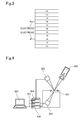
- FIG. 1 is a schematic cross-sectional diagram illustrating an embodiment of an electrochromic element of the present invention.
- This electrochromic element of FIG. 1 is configured to include a transparent base material 10, a transparent electrode layer 20, an ion storage layer 30, a non-water-based hydrogen ion conductive electrolyte layer 90, a catalyst layer 40, a reflective dimming layer 50, a transparent electrode layer 60, and a transparent base material 70. Then, an electrode for switching is connected to the transparent electrode layer 20 and the transparent electrode 60.
- the transparent electrode layer 20 and the ion storage layer 30 are formed on the transparent base material 10
- the transparent electrode layer 60, the reflective dimming layer 50 and the catalyst layer 40 are formed on the transparent base material 70
- a non-water-based hydrogen ion conductive electrolyte solution 80 is interposed between the ion storage layer 30 and the catalyst layer 40 of those two members.
- the non-water-based hydrogen ion conductive electrolyte solution 80 functions as a non-water-based hydrogen ion conductive electrolyte layer 90.
- the term "on” used in the descriptions such as “on the catalyst layer” has a meaning specifying the direction of the layer that is laminated, and does not necessarily mean that the layer is disposed adjacently.
- the term "the catalyst layer is formed on the reflective dimming layer” there are a case in which the reflective dimming layer and the catalyst layer are disposed adjacently, and a case in which the reflective dimming layer and the catalyst layer are disposed with another layer interposed therebetween.
- the technical scope of the present invention is not intended to be limited to the above-described embodiment.
- a configuration in which a reflective dimming layer 50 and a catalyst layer 40 are formed directly on a transparent base material 70 can be adopted.
- an electrode for switching is connected to a transparent electrode layer 20 and the reflective dimming layer 50.
- a transparent electrode layer 60 is unnecessary, the configuration is advantageous in view of cost, and is superior in increasing the transmittance of the transparent state.
- an embodiment of further sandwiching the element with a pair of glass plates as illustrated in FIG. 3 can be adopted.
- FIG. 3 illustrates a schematic cross-sectional diagram of a reflective dimming plate in which an electrochromic element is sandwiched with a pair of glass plates 110.
- An intermediate film 100 for laminated glass which is made of polyvinyl butyral or the like, may be interposed between the glass plate 110 and the electrochromic element, as necessary.
- the electrochromic element of the present invention is suitably applied to, for example, dimming members for construction members or parts for transport vehicles such as automobiles, due to the function of the element.
- window glass is a representative member for application.
- examples of applications can include window glass, outer panels and interior decorations.
- the thin films that constitute the various layers of the electrochromic element of the present invention may be formed using generally known film forming methods without any particular limitations.
- these film forming methods may include methods such as a magnetron sputtering method, a vacuum deposition method, an electron beam deposition method, a chemical vapor deposition (CVD) method, a plating method, a dip coating method, and a spin coating method.
- the size of the transparent base material is determined according to the design of the vehicle. Furthermore, the thickness is also determined in consideration of the light transmittance, strength and the like of the dimming material.
- a transparent electrode layer 20 and an ion storage layer 30 are formed on a transparent base material 10, and a transparent electrode layer 60, a reflective dimming layer 50 such as a thin film of a magnesium-nickel-based alloy, a magnesium-titanium-based alloy, a magnesium-niobium-based alloy or a magnesium-zirconium-based alloy, and a catalyst layer 40 are formed on another transparent base material 70.
- a transparent electrode layer 20 and an ion storage layer 30 are formed on a transparent base material 10
- a transparent electrode layer 60, a reflective dimming layer 50 such as a thin film of a magnesium-nickel-based alloy, a magnesium-titanium-based alloy, a magnesium-niobium-based alloy or a magnesium-zirconium-based alloy, and a catalyst layer 40 are formed on another transparent base material 70.
- the dimming operation of the reflective dimming electrochromic element in the embodiments of FIG. 1 and FIG. 3 is carried out by applying a voltage/current between the transparent electrode layer 20 and the transparent electrode layer 60. That is, when the electrochromic element is in the mirror state, if a positive voltage is applied to the transparent electrode layer 20 and a negative voltage is applied to the transparent electrode layer 60, the hydrogen ions stored in the ion storage layer 30 diffuse through the non-water-based hydrogen ion conductive electrolyte layer 90 and the catalyst layer 40 to the reflective dimming layer 50, and the reflective dimming layer 50 is transformed into a hydrogen compound. Therefore, the reflection characteristics of the layer are changed from the mirror state to the transmissive state.
- the catalyst layer 40 has a function of accelerating the giving and receiving of hydrogen ions between the non-water-based hydrogen ion conductive electrolyte layer 90 and the reflective dimming layer 50, and a sufficient switching rate at the reflective dimming layer 50 is secured by the catalyst layer 40.
- the electrochromic element when the electrochromic element is in the transparent state, if a negative voltage is applied to the ion storage layer 20, and a positive voltage is applied to the transparent electrode layer 60, hydrides in the reflective dimming layer 50 are dehydrogenated, and the reflection characteristics are reverted from the transparent state to the mirror state. Released hydrogen returns in the form of hydrogen ions through the catalyst layer 40 and the non-water-based hydrogen ion conductive electrolyte layer 90 to the ion storage layer 30, where hydrogen is stored.
- the reflective dimming layer 50 takes the function of the transparent electrode layer 60 described above as well.
- the present invention when layers are formed on two sheets of transparent base materials as described above, and for example, a non-water-based hydrogen ion conductive electrolyte solution having adhesiveness is interposed between the layers, production of the element is enabled only by conveniently bonding the layers by the same effect as that given by normal adhesives, and furthermore a reflective dimming electrochromic element which exhibits variability of the total light transmittance and total light reflectance at an arbitrary wavelength due to the components of the non-water-based hydrogen ion conductive electrolyte layer used, and a dimming member having the element incorporated therein can be provided.
- the present invention is useful as a practical reflective dimming electrochromic material and as a dimming member.
- Examples 1 to 11 are examples related to elements each produced using a non-water-based hydrogen ion conductive electrolyte solution containing an ion conductive polymer, an organic solvent and additives
- Examples 12 to 16 are examples related to elements each produced using a non-water-based hydrogen ion conductive electrolyte solution containing an ion conductive polymer and an organic solvent.
- the various components of the non-water-based hydrogen ion conductive electrolyte solutions, and comparisons with known methods are described in Examples 17 to 19.
- Example 1 of the present invention will be described.
- a reflective dimming electrochromic element was produced to have the configuration illustrated in FIG. 1 .
- a glass plate having a thickness of 1.1 mm was used as a transparent base material 10, and was coated with a tin-doped indium oxide having a surface resistivity of 10 ⁇ / ⁇ as a transparent electrode layer 20.
- This was mounted in a vacuum apparatus, and the apparatus was evacuated to a vacuum.
- vapor deposition of a tungsten oxide thin film as an ion storage layer 30 was carried out using a magnetron sputtering apparatus. Film formation was carried out using a reactive DC magnetron sputtering method of sputtering a tungsten metal target in a mixed atmosphere of argon and oxygen.
- the mixed atmosphere was controlled by controlling the flow rate of argon gas and oxygen gas.
- the ratio of flow rate of argon gas and oxygen gas was 7:1.5, and film formation was carried out by the DC magnetron sputtering method by applying a power of 80 W to tungsten, at a pressure inside the vacuum chamber of 1.0 Pa.
- the film thickness of the tungsten oxide thin film thus produced was about 500 nm.
- a glass plate having a thickness of 1.1 mm was used as a transparent base material 70, and was coated with a tin-doped indium oxide having a surface resistivity of 10 ⁇ / ⁇ as a transparent electrode layer 60.
- vapor deposition of a magnesium-nickel alloy thin film as a reflective dimming layer 50 and palladium as a catalyst layer 40 was carried out sequentially using a triple magnetron sputtering apparatus. Magnesium metal, nickel metal and palladium metal were respectively mounted on three sputter guns as targets.
- a power of 30 W was applied to magnesium, a power of 16 W was applied to nickel, and thus a reflective dimming layer 50 formed of a magnesium-nickel alloy thin film having a thickness of about 40 nm was deposited.
- the composition of magnesium and nickel at this time was almost Mg 4 Ni.
- palladium metal was sputtered, and thus a palladium thin film having a thickness of about 4 nm as a catalyst layer 40 was deposited.
- the argon gas pressure during sputtering was 1.2 Pa, and a power of 18 W was applied to palladium by a DC magnetron sputtering method to perform sputtering.
- a non-water-based hydrogen ion conductive electrolyte solution 80 was prepared. First, 0.1 ml of polyethyleneimine (molecular weight 600) as an ion conductive polymer was measured off and was diluted in 10 ml of anhydrous ethanol. After dissolving the polymer, 0.10 g to 0.75 g of polyvinyl butyral (degree of polymerization 2400) was added thereto. The hydrogen ion index of the solution thus prepared was 12. Subsequently, the solution 80 was applied on the ion storage layer 30 formed from a tungsten oxide thin film on the transparent base material 10, and thereafter, the transparent base material 70 was covered to cause the solution to adhere closely to the palladium catalyst layer 40 on the transparent base material 70. Thus, a laminated structure was produced.
- polyethyleneimine molecular weight 600
- polyvinyl butyral degree of polymerization 2400
- the element thus obtained was mounted on an evaluation apparatus as illustrated in FIG. 4 , and the optical switching characteristics were investigated by connecting electrodes to the transparent electrode layer 20 on the transparent base material 10 and the transparent electrode layer 60 on the transparent base material 70, respectively.
- the initial state of this switching element was a mirror state.
- a voltage of ⁇ 2.5 V was applied between the electrodes, and the changes in the optical transmittance and the optical reflectance at that time were measured with a measurement system combining a semiconductor laser having a wavelength of 670 nm and a silicon photodiode.
- the diagram shows the reflective dimming electrochromic element 501 thus produced, a semiconductor laser 502, a Si photodiode 503, a digital multimeter 504, a SourceMeter 505, and a computer 507.
- the element produced using the non-water-based hydrogen ion conductive electrolyte solution 80 containing 0.10 g of polyvinyl butyral as described above is such that since the magnesium-nickel-based alloy thin film as the reflective dimming layer 50 has metallic gloss, the thin film reflects light satisfactorily (optical reflectance: about 44%), and since the tungsten oxide thin film as the ion storage layer 30 is colored dark blue, the transmittance is very low (optical transmittance: about 0.2%).
- the hydrogen ions in the ion storage layer 30 formed from a tungsten oxide thin film diffused into a non-water-based hydrogen ion conductive electrolyte layer 90, and were introduced through the palladium catalyst layer 40 to the reflective dimming layer 50 formed from a magnesium-nickel-based alloy thin film.
- the ion storage layer 30 formed from a tungsten oxide thin film became transparent, and the reflective dimming layer 50 formed from a magnesium-nickel-based alloy thin film also underwent hydrogenation and became transparent (optical reflectance: about 15%, optical transmittance: about 32%).
- the changes over time in the optical transmittance and the optical reflectance at this time were measured with respect to the amount of addition of polyvinyl butyral (PVB, degree of polymerization: 2400), and the data are presented in FIG. 5(a) and FIG. 5(b) . As shown in FIG.
- the transmission spectra of the element before and after switching are presented in FIG. 6 . As shown in FIG. 6 , it is understood that the transmission spectrum at the measurement wavelength undergoes a significant change by switching.
- the present element can reversibly switch between a reflective state and a transmissive state by changing the polarity of the applied voltage. As such, it was confirmed that convenient element production was achievable by laminating transparent base materials to each other using the non-water-based hydrogen ion conductive electrolyte solution 80, and the element thus produced exhibited excellent dimming characteristics.
- an ion storage layer 30 tungsten oxide was deposited on a transparent base material 10 formed from a glass substrate coated with tin-doped indium oxide as a transparent electrode layer 20, and deposition of various thin films of a transparent electrode layer 60 : tin-doped indium oxide/a reflective dimming layer 50 : a magnesium-nickel-based alloy/a catalyst layer 40 : palladium was carried out on a transparent base material 70 formed from a glass substrate, using a magnetron sputtering method.
- the various film forming conditions are the same as in Example 1.
- a non-water-based hydrogen ion conductive electrolyte solution 80 was prepared by measuring off 0.1 ml of polyethyleneimine (molecular weight 600) as an ion conductive polymer, diluting the polymer in 10 ml of ⁇ -butyrolactone, dissolving the polymer, and then adding 0.10 g to 0.50 g of polyvinylpyrrolidone (PVP) K25 thereto.
- the hydrogen ion index of the solution 80 thus prepared was 12.
- the solution 80 was applied on the ion storage layer 30 formed from a tungsten oxide thin film on the transparent base material 10 formed from a glass substrate, and subsequently, the transparent base material 70 formed from a glass substrate was covered to cause the solution to adhere closely to the palladium catalyst layer 40 on the transparent base material 70. Thus, a laminated structure was produced.
- the element thus obtained was mounted on the evaluation apparatus as illustrated in FIG. 4 in the same manner as in Example 1, and the optical switching characteristics were investigated by connecting electrodes to the transparent electrode layer 20 on the transparent base material 10 and the transparent electrode layer 60 on the transparent base material 70, respectively.
- the initial state of this switching element was a mirror state.
- a voltage of ⁇ 2.5 V was applied between the electrodes, and the changes in the optical transmittance and the optical reflectance at that time were measured with the measurement system combining the semiconductor laser having a wavelength of 670 nm and the silicon photodiode.
- the element produced using the non-water-based hydrogen ion conductive electrolyte solution 80 containing 0.10 g of polyvinylpyrrolidone is such that since the magnesium-nickel-based alloy thin film as the reflective dimming layer 50 has metallic gloss, the thin film reflects light satisfactorily (optical reflectance: about 44%), and since the tungsten oxide thin film as the ion storage layer 30 is colored dark blue, the transmittance is very low (optical transmittance: about 0.2%).
- the hydrogen ions in the ion storage layer 30 formed from a tungsten oxide thin film diffused into a non-water-based hydrogen ion conductive electrolyte layer 90, and were introduced through the palladium catalyst layer 40 to the reflective dimming layer 50 formed from a magnesium-nickel-based alloy thin film.
- the ion storage layer 30 formed from the tungsten oxide thin film became transparent, and the reflective dimming layer 50 formed from the magnesium-nickel-based alloy thin film also underwent hydrogenation and became transparent (optical reflectance: about 16%, optical transmittance: about 31%).
- the changes over time in the optical transmittance and the optical reflectance were measured with respect to the amount of addition of polyvinyl pyrrolidone (PVP) K25, and the data are presented in FIG. 7(a) and FIG. 7(b) . As shown in FIG. 7(a) and FIG.
- FIG. 8 the transmission spectra of the element before and after switching are presented in FIG. 8 . As shown in FIG. 8 , it is understood that the transmission spectrum at the measurement wavelength undergoes a significant change by switching.
- the present element can reversibly switch between a reflective state and a transmissive state by changing the polarity of the applied voltage. As such, it was confirmed that convenient element production was achievable by bonding transparent base materials to each other using the non-water-based hydrogen ion conductive electrolyte solution 80, and the element thus produced exhibited excellent dimming characteristics.
- an ion storage layer 30 tungsten oxide was deposited on a transparent base material 10 formed from a glass substrate coated with tin-doped indium oxide as a transparent electrode layer 20, and deposition of various thin films of a transparent electrode layer 60 : tin-doped indium oxide/a reflective dimming layer 50 : a magnesium-nickel-based alloy/a catalyst layer 40 : palladium was carried out on a glass substrate 2, using a magnetron sputtering method.
- the various film forming conditions are the same as in Example 1.
- a non-water-based hydrogen ion conductive electrolyte solution 80 was prepared by measuring off 0.1 ml of polyethyleneimine (molecular weight 600) as an ion conductive polymer, diluting the polymer in 10 ml of propylene carbonate, dissolving the polymer, and then adding 0.25 g of polyvinylpyrrolidone (PVP) K25 thereto.
- the hydrogen ion index of the solution 80 thus prepared was 12.
- the solution 80 was applied on the ion storage layer 30 formed from the tungsten oxide thin film on the transparent base material 10 formed from the glass substrate, and subsequently, a transparent base material 70 formed from a glass substrate was covered to cause the solution to adhere closely to the palladium catalyst layer 40 on the transparent base material 70. Thus, a laminated structure was produced.
- the element thus obtained was mounted on the evaluation apparatus as illustrated in FIG. 4 in the same manner as in Example 1, and the optical switching characteristics were investigated by connecting electrodes to the transparent electrode layer 20 on the transparent base material 10 and the transparent electrode layer 60 on the transparent base material 70.
- the initial state of this switching element was a mirror state.
- a voltage of ⁇ 2.5 V was applied between the electrodes, and the changes in the optical transmittance and the optical reflectance at that time were measured with a measurement system combining the semiconductor laser having a wavelength of 670 nm and the silicon photodiode.
- the element immediately after production is such that since the magnesium-nickel-based alloy thin film as the reflective dimming layer 50 has metallic gloss, the thin film reflects light satisfactorily (optical reflectance: about 46%), and since the tungsten oxide thin film as the ion storage layer 30 is colored dark blue, the transmittance is very low (optical transmittance: about 0.2%).
- the hydrogen ions in the ion storage layer 30 formed from the tungsten oxide thin film diffused into a non-water-based hydrogen ion conductive electrolyte layer 90, and were introduced through the palladium catalyst layer 40 to the reflective dimming layer 50 formed from the magnesium-nickel-based alloy thin film.
- the ion storage layer 30 formed from the tungsten oxide thin film became transparent, and the reflective dimming layer 50 formed from the magnesium-nickel-based alloy thin film also underwent hydrogenation and became transparent (optical reflectance: about 9%, optical transmittance: about 30%).
- the changes over time in the optical transmittance and the optical reflectance are presented in FIG. 9(a) and FIG. 9(b) . As shown in FIG. 9(a) and FIG.
- the present element can reversibly switch between a reflective state and a transmissive state by changing the polarity of the applied voltage. As such, it was confirmed that convenient element production was achievable by laminating transparent base materials to each other using the non-water-based hydrogen ion conductive electrolyte solution 80, and the element thus produced exhibited excellent dimming characteristics.
- an ion storage layer 30 tungsten oxide was deposited on a transparent base material 10 formed from a glass substrate coated with tin-doped indium oxide as a transparent electrode layer 20, and deposition of various thin films of a transparent electrode layer 60 : tin-doped indium oxide/a reflective dimming layer 50 : a magnesium-nickel-based alloy/a catalyst layer 40 : palladium was carried out on a transparent base material 70 formed from a glass substrate, using a magnetron sputtering method.
- the various film forming conditions are the same as in Example 1.
- a non-water-based hydrogen ion conductive electrolyte solution 80 was prepared by measuring off 0.1 ml of polyethyleneimine (molecular weight 600) as an ion conductive polymer, diluting the polymer in 10 ml of tetrahydrofuran, dissolving the polymer, and then adding 1 g of a polysilane (SI-10-10 manufactured by Osaka Gas Chemicals Co., Ltd.) thereto.
- the hydrogen ion index of the solution 80 thus prepared was 12.
- the solution 80 was applied on the ion storage layer 30 formed from the tungsten oxide thin film on the transparent base material 10 formed from the glass substrate, and subsequently, the transparent base material 70 formed from the glass substrate was covered to cause the solution to adhere closely to the palladium catalyst layer 40 on the transparent base material 70. Thus, a laminated structure was produced.
- the solution was irradiated with ultraviolet radiation at a wavelength of 365 nm for about 3 minutes using an ultraviolet curing apparatus having an ultraviolet radiation intensity of 170 mW/cm 2 .
- the element thus obtained was mounted on the evaluation apparatus as illustrated in FIG. 4 in the same manner as in Example 1, and the optical switching characteristics were investigated by connecting electrodes to the transparent electrode layer 20 on the transparent base material 10 and the transparent electrode layer 60 on the transparent base material 70.
- the initial state of this switching element was a mirror state.
- a voltage of ⁇ 2 V was applied between the electrodes, and the changes in the optical transmittance and the optical reflectance at that time were measured with the measurement system combining the semiconductor laser having a wavelength of 670 nm and the silicon photodiode.
- the element immediately after production is such that since the magnesium-nickel-based alloy thin film as the reflective dimming layer 50 has metallic gloss, the thin film reflects light satisfactorily (optical reflectance: about 51%), and since the tungsten oxide thin film as the ion storage layer 30 is colored dark blue, the transmittance is very low (optical transmittance: about 0.2%).
- the hydrogen ions in the ion storage layer 30 formed from the tungsten oxide thin film diffused into a non-water-based hydrogen ion conductive electrolyte layer 90, and were introduced through the palladium catalyst layer 40 to the reflective dimming layer 50 formed from the magnesium-nickel-based alloy thin film.
- the ion storage layer 30 formed from a tungsten oxide thin film became transparent, and the reflective dimming layer 50 formed from a magnesium-nickel-based alloy thin film also underwent hydrogenation and became transparent (optical reflectance: about 9%, optical transmittance: about 30%).
- the changes over time in the optical transmittance and the optical reflectance at this time are presented in FIG.10(a) and FIG. 10(b) . As shown in FIG. 10(a) and FIG.
- the present element can reversibly switch between a reflective state and a transmissive state by changing the polarity of the applied voltage. As such, it was confirmed that convenient element production was achievable by laminating transparent base materials to each other using the non-water-based hydrogen ion conductive electrolyte solution 80, and the element thus produced exhibited excellent dimming characteristics.
- an ion storage layer 30 tungsten oxide was deposited on a transparent base material 10 formed from a glass substrate coated with tin-doped indium oxide as a transparent electrode layer 20, and deposition of various thin films of a transparent electrode layer 60 : tin-doped indium oxide/a reflective dimming layer 50 : a magnesium-nickel-based alloy/a catalyst layer 40 : palladium was carried out on a transparent base material 70 formed from a glass substrate, using a magnetron sputtering method.
- the various film forming conditions are the same as in Example 1.
- a non-water-based hydrogen ion conductive electrolyte solution 80 was prepared by measuring off 0.1 ml of polyethyleneimine (molecular weight 600) as an ion conductive polymer, diluting the polymer in 10 ml of tetrahydrofuran, dissolving the polymer, and then adding 0.5 g of polyvinylidene fluoride thereto.
- the hydrogen ion index of the solution 80 thus prepared was 12.
- the solution 80 was applied on the ion storage layer 30 formed from the tungsten oxide thin film on the transparent base material 10 formed from the glass substrate, and subsequently, the transparent base material 70 formed from the glass substrate was covered to cause the solution to adhere closely to the palladium catalyst layer 40 on the transparent base material 70. Thus, a laminated structure was produced.
- the element thus obtained was mounted on the evaluation apparatus as illustrated in FIG. 4 in the same manner as in Example 1, and the optical switching characteristics were investigated by connecting electrodes to the transparent electrode layer 20 on the transparent base material 10 and the transparent electrode layer 60 on the transparent base material 70.
- the initial state of this switching element was a mirror state.
- a voltage of ⁇ 2.5 V was applied between the electrodes, and the changes in the optical transmittance and the optical reflectance at that time were measured with the measurement system combining the semiconductor laser having a wavelength of 670 nm and the silicon photodiode.
- the element immediately after production is such that since the magnesium-nickel-based alloy thin film as the reflective dimming layer 50 has metallic gloss, the thin film reflects light satisfactorily (optical reflectance: about 48%), and since the tungsten oxide thin film as the ion storage layer 30 is colored dark blue, the transmittance is very low (optical transmittance: about 0.2%).
- the hydrogen ions in the ion storage layer 30 formed from the tungsten oxide thin film diffused into a non-water-based hydrogen ion conductive electrolyte layer 90, and were introduced through the palladium catalyst layer 40 to the reflective dimming layer 50 formed from the magnesium-nickel-based alloy thin film.
- the ion storage layer 30 formed from the tungsten oxide thin film became transparent, and the reflective dimming layer 50 formed from the magnesium-nickel-based alloy thin film also underwent hydrogenation and became transparent (optical reflectance: about 10%, optical transmittance: about 33%).
- the changes over time in the optical transmittance and the optical reflectance at this time are presented in FIG. 11(a) and FIG. 11(b) . As shown in FIG. 11(a) and FIG.
- the present element can reversibly switch between a reflective state and a transmissive state by changing the polarity of the applied voltage. As such, it was confirmed that convenient element production was achievable by laminating transparent base materials to each other using the non-water-based hydrogen ion conductive electrolyte solution 80, and the element thus produced exhibited excellent dimming characteristics.
- an ion storage layer 30 tungsten oxide was deposited on a transparent base material 10 formed from a glass substrate coated with tin-doped indium oxide as a transparent electrode layer 20, and a transparent electrode layer 60: tin-doped indium oxide was deposited on a transparent base material 70 formed from a glass substrate.
- a reflective dimming layer 50 was prepared using a magnesium-titanium-based alloy, applying a power of 25 W to magnesium and a power of 25 W to titanium, and depositing a magnesium titanium alloy thin film having a thickness of about 40 nm. The composition of magnesium and titanium at this time was almost Mg 9 Ti. Thereafter, deposition of various thin films of a catalyst layer 40: palladium was carried out using a magnetron sputtering method.
- a non-water-based hydrogen ion conductive electrolyte solution 80 was prepared by measuring off 0.1 ml of polyethyleneimine (molecular weight 600) as an ion conductive polymer, diluting the polymer in 10 ml of tetrahydrofuran, dissolving the polymer, and then adding 0.10 g to 0.75 g of polyvinyl butyral (PVB, degree of polymerization: 2400) thereto.
- the hydrogen ion index of the solution 80 thus prepared was 12.
- the solution 80 was applied on the ion storage layer 30 formed from the tungsten oxide thin film on the transparent base material 10 formed from the glass substrate, and subsequently, the transparent base material 70 formed from the glass substrate was covered to cause the solution to adhere closely to the palladium catalyst layer 40 on the transparent base material 70. Thus, a laminated structure was produced.
- the element thus obtained was mounted on the evaluation apparatus as illustrated in FIG. 4 in the same manner as in Example 1, and the optical switching characteristics were investigated by connecting electrodes to the transparent electrode layer 20 on the transparent base material 10 and the transparent electrode layer 60 on the transparent base material 70.
- the initial state of this switching element was a mirror state.
- a voltage of ⁇ 2.5 V was applied between the electrodes, and the changes in the optical transmittance and the optical reflectance at that time were measured with the measurement system combining the semiconductor laser having a wavelength of 670 nm and the silicon photodiode.
- the element produced using the non-water-based hydrogen ion conductive electrolyte solution 80 containing 0.10 g of polyvinyl butyral is such that since the magnesium-titanium-based alloy thin film as the reflective dimming layer 50 has metallic gloss, the thin film reflects light satisfactorily (optical reflectance: about 51%), and since the tungsten oxide thin film as the ion storage layer 30 is colored dark blue, the transmittance is very low (optical transmittance: about 0.2%).
- the hydrogen ions in the ion storage layer 30 formed from the tungsten oxide thin film diffused into a non-water-based hydrogen ion conductive electrolyte layer 90, and were introduced through the palladium catalyst layer 40 to the reflective dimming layer 50 formed from the magnesium-titanium-based alloy thin film.
- the ion storage layer 30 formed from a tungsten oxide thin film became transparent, and the reflective dimming layer 50 formed from a magnesium-titanium-based alloy thin film also underwent hydrogenation and became transparent (optical reflectance: about 13%, optical transmittance: about 29%).
- the changes over time in the optical transmittance and the optical reflectance at this time were measured with respect to the amount of addition of polyvinyl butyral (PVB, degree of polymerization: 2400), and the data are presented in FIG. 12(a) and FIG. 12(b) . As shown in FIG. 12(a) and FIG.
- the element in the element which used a mixed solution of polyethyleneimine, tetrahydrofuran and polyvinyl butyral as the non-water-based hydrogen ion conductive electrolyte solution 80, the element similarly exhibited the transmissive state after voltage application, and when a voltage of +2.5 V was applied after completion of the transparent state, the transmittance was decreased, causing the element to return to the reflective state.
- the present element can reversibly switch between a reflective state and a transmissive state by changing the polarity of the applied voltage. As such, it was confirmed that convenient element production was achievable by laminating transparent base materials to each other using the non-water-based hydrogen ion conductive electrolyte solution 80, and the element thus produced exhibited excellent dimming characteristics.
- an ion storage layer 30 tungsten oxide was deposited on a transparent base material 10 formed from a glass substrate coated with tin-doped indium oxide as a transparent electrode layer 20, and deposition of various thin films of a transparent electrode layer 60: tin-doped indium oxide/a reflective dimming layer 50: a magnesium-titanium-based alloy/a catalyst layer 40: palladium was carried out on a transparent base material 70 formed from a glass substrate, using a magnetron sputtering method.
- a non-water-based hydrogen ion conductive electrolyte solution 80 was prepared by measuring off 0.1 ml of polyethyleneimine (molecular weight 600) as an ion conductive polymer, diluting the polymer in 10 ml of anhydrous ethanol, dissolving the polymer, and then adding 0.10 g to 0.50 g of polyvinyl butyral (PVB, degree of polymerization: 2400) thereto.
- the hydrogen ion index of the solution 80 thus prepared was 12.
- the solution 80 was applied on the ion storage layer 30 formed from the tungsten oxide thin film on the transparent base material 10 formed from the glass substrate, and subsequently, the transparent base material 70 formed from the glass substrate was covered to cause the solution to adhere closely to the palladium catalyst layer 40 on the transparent base material 70. Thus, a laminated structure was produced.
- the element thus obtained was mounted on the evaluation apparatus as illustrated in FIG. 4 in the same manner as in Example 1, and the optical switching characteristics were investigated by connecting electrodes to the transparent electrode layer 20 on the transparent base material 10 and the transparent electrode layer 60 on the transparent base material 70.
- the initial state of this switching element was a mirror state.
- a voltage of ⁇ 1.5 V was applied between the electrodes, and the changes in the optical transmittance and the optical reflectance at that time were measured with the measurement system combining the semiconductor laser having a wavelength of 670 nm and the silicon photodiode.
- the element produced using the non-water-based hydrogen ion conductive electrolyte solution 80 containing 0.10 g of polyvinyl butyral is such that since the magnesium-titanium-based alloy thin film as the reflective dimming layer 50 has metallic gloss, the thin film reflects light satisfactorily (optical reflectance: about 45%), and since the tungsten oxide thin film as the ion storage layer 30 is colored dark blue, the transmittance is very low (optical transmittance: about 0.2%).
- the ion storage layer 30 formed from the tungsten oxide thin film became transparent, and the reflective dimming layer 50 formed from the magnesium-titanium-based alloy thin film also underwent hydrogenation and became transparent (optical reflectance: about 12%, optical transmittance: about 30%).
- the changes over time in the optical transmittance and the optical reflectance at this time were measured with respect to the amount of addition of polyvinyl butyral (PVB, degree of polymerization: 2400), and the data are presented in FIG. 13(a) and FIG. 13(b) . As shown in FIG. 13(a) and FIG.
- the present element can reversibly switch between a reflective state and a transmissive state by changing the polarity of the applied voltage. As such, it was confirmed that convenient element production was achievable by laminating transparent base materials to each other using the non-water-based hydrogen ion conductive electrolyte solution 80, and the element thus produced exhibited excellent dimming characteristics.
- An ion storage layer 30 tungsten oxide was deposited on a transparent base material 10 formed from a glass substrate coated with tin-doped indium oxide as a transparent electrode layer 20, and deposition of various thin films of a transparent electrode layer 60: tin-doped indium oxide/a reflective dimming layer 50: a magnesium-nickel-based alloy/a catalyst layer 40: palladium was carried out on a transparent base material 70 formed from a polyethylene terephthalate (PET) resin substrate, using a magnetron sputtering method.
- PET polyethylene terephthalate
- a non-water-based hydrogen ion conductive electrolyte solution 80 was prepared by measuring off 0.1 ml of polyethyleneimine (molecular weight 600) as an ion conductive polymer, diluting the polymer in 10 ml of tetrahydrofuran, dissolving the polymer, and then adding 0.50 g of polyvinyl butyral (PVB, degree of polymerization: 2400) thereto.
- the hydrogen ion index of the solution 80 thus prepared was 12.
- the solution 80 was applied on the ion storage layer 30 formed from the tungsten oxide thin film on the transparent base material 10 formed from the glass substrate, and subsequently, the transparent base material 70 formed from the PET substrate was covered to cause the solution to adhere closely to the palladium catalyst layer 40 on the transparent base material 70. Thus, a laminated structure was produced.
- the element thus obtained was mounted on the evaluation apparatus as illustrated in FIG. 4 in the same manner as in Example 1, and the optical switching characteristics were investigated by connecting electrodes to the transparent electrode layer 20 on the transparent base material 10 formed from the glass base material and the transparent electrode layer 60 on the transparent base material 70 formed from the PET base material.
- the initial state of this switching element was a mirror state.
- a voltage of ⁇ 5 V was applied between the electrodes, and the changes in the optical transmittance and the optical reflectance at that time were measured with the measurement system combining the semiconductor laser having a wavelength of 670 nm and the silicon photodiode.
- the element immediately after production is such that since the magnesium-nickel-based alloy thin film as the reflective dimming layer 50 has metallic gloss, the thin film reflects light satisfactorily (optical reflectance: about 49%), and since the tungsten oxide thin film as the ion storage layer 30 is colored dark blue, the transmittance is very low (optical transmittance: about 0.2%).
- the hydrogen ions in the ion storage layer 30 formed from the tungsten oxide thin film diffused into a non-water-based hydrogen ion conductive electrolyte layer 90, and were introduced through the palladium catalyst layer 40 to the reflective dimming layer 50 formed from the magnesium-nickel-based alloy thin film.
- the ion storage layer 30 formed from the tungsten oxide thin film became transparent, and the reflective dimming layer 50 formed from the magnesium-nickel-based alloy thin film also underwent hydrogenation and became transparent (optical reflectance: about 15%, optical transmittance: about 30%).
- the changes over time in the optical transmittance and the optical reflectance at this time are presented in FIG. 14(a) and FIG. 14(b) . As shown in FIG. 14(a) and FIG.
- the element in the element which used a mixed solution of polyethyleneimine, tetrahydrofuran and polyvinyl butyral as the non-water-based hydrogen ion conductive electrolyte solution 80, the element similarly exhibited the transmissive state after voltage application, and when a voltage of +5 V was applied after completion of the transparent state, the transmittance was decreased, causing the element to return to the reflective state.
- the present element can reversibly switch between a reflective state and a transmissive state by changing the polarity of the applied voltage. As such, it was confirmed that convenient element production was achievable by laminating transparent base materials to each other using the non-water-based hydrogen ion conductive electrolyte solution 80, and the element thus produced exhibited excellent dimming characteristics.
- an ion storage layer 30 tungsten oxide was deposited on a transparent base material 10 formed from a glass substrate coated with tin-doped indium oxide as a transparent electrode layer 20, and deposition of various thin films of a transparent electrode layer 60: tin-doped indium oxide/a reflective dimming layer 50: a magnesium-nickel-based alloy/a catalyst layer 40: palladium was carried out on a transparent base material 70 formed from a glass substrate, using a magnetron sputtering method.
- the various film forming conditions are the same as in Example 1.
- a non-water-based hydrogen ion conductive electrolyte solution 80 was prepared by measuring off 0.1 ml of polyethyleneimine (molecular weight 600) as an ion conductive polymer, diluting the polymer in a mixed solution of 5 ml of tetrahydrofuran and 5 ml of propylene carbonate, dissolving the polymer, and then adding 0.1 g of 12-hydroxystearic acid thereto.
- the hydrogen ion index of the solution 80 thus prepared was 12.
- the solution 80 was applied on the ion storage layer 30 formed from the tungsten oxide thin film on the transparent base material 10 formed from the glass substrate, and subsequently, the transparent base material 70 formed from the glass substrate was covered to cause the solution to adhere closely to the palladium catalyst layer 40 on the transparent base material 70. Thus, a bonded structure was produced.
- the element thus obtained was mounted on the evaluation apparatus as illustrated in FIG. 4 in the same manner as in Example 1, and the optical switching characteristics were investigated by connecting electrodes to the transparent electrode layer 20 on the transparent base material 10 and the transparent electrode layer 60 on the transparent base material 70.
- the initial state of this switching element was a mirror state.
- a voltage of ⁇ 2.5 V was applied between the electrodes, and the changes in the optical transmittance and the optical reflectance at that time were measured with the measurement system combining the semiconductor laser having a wavelength of 670 nm and the silicon photodiode.
- the element immediately after production is such that since the magnesium-nickel-based alloy thin film as the reflective dimming layer 50 has metallic gloss, the thin film reflects light satisfactorily (optical reflectance: about 47%), and since the tungsten oxide thin film as the ion storage layer 30 is colored dark blue, the transmittance is very low (optical transmittance: about 0.2%).
- the hydrogen ions in the ion storage layer 30 formed from the tungsten oxide thin film diffused into a non-water-based hydrogen ion conductive electrolyte layer 90, and were introduced through the palladium catalyst layer 40 to the reflective dimming layer 50 formed from the magnesium-nickel-based alloy thin film.
- the ion storage layer 30 formed from the tungsten oxide thin film became transparent, and the reflective dimming layer 50 formed from the magnesium-nickel-based alloy thin film also underwent hydrogenation and became transparent (optical reflectance: about 10%, optical transmittance: about 32%).
- the changes over time in the optical transmittance and the optical reflectance at this time are presented in FIG. 15(a) and FIG. 15(b) . As shown in FIG. 15(a) and FIG.
- the element in the element which used a mixed solution of polyethyleneimine, tetrahydrofuran, propylene carbonate and 12-hydroxystearic acid as the non-water-based hydrogen ion conductive electrolyte solution 80, the element similarly exhibited the transmissive state after voltage application, and when a voltage of +2.5 V was applied after completion of the transparent state, the transmittance was decreased, causing the element to return to the reflective state.
- the present element can reversibly switch between a reflective state and a transmissive state by changing the polarity of the applied voltage. As such, it was confirmed that convenient element production was achievable by laminating transparent base materials to each other using the non-water-based hydrogen ion conductive electrolyte solution 80, and the element thus produced exhibited excellent dimming characteristics.
- an ion storage layer 30 tungsten oxide was deposited on a transparent base material 10 formed from a glass substrate coated with tin-doped indium oxide as a transparent electrode layer 20, and deposition of various thin films of a transparent electrode layer 60: tin-doped indium oxide/a reflective dimming layer 50: a magnesium-nickel-based alloy/a catalyst layer 40: palladium was carried out on a transparent base material 70 formed from a glass substrate, using a magnetron sputtering method.
- the various film forming conditions are the same as in Example 1.
- a non-water-based hydrogen ion conductive electrolyte solution 80 was prepared by measuring off 0.1 ml of polyethyleneimine (molecular weight 600) as an ion conductive polymer, diluting the polymer in 10 ml of 1,3-dioxolane, dissolving the polymer, and then adding 0.5 g of polyvinyl butyral (PVB, degree of polymerization: 2400) thereto.
- the hydrogen ion index of the solution 80 thus prepared was 12.
- the solution 80 was applied on the ion storage layer 30 formed from the tungsten oxide thin film on the transparent base material 10 formed from the glass substrate, and subsequently, the transparent base material 70 formed from the glass substrate was covered to cause the solution to adhere closely to the palladium catalyst layer 40 on the transparent base material 70. Thus, a laminated structure was produced.
- the element thus obtained was mounted on the evaluation apparatus as illustrated in FIG. 4 in the same manner as in Example 1, and the optical switching characteristics were investigated by connecting electrodes to the transparent electrode layer 20 on the transparent base material 10 and the transparent electrode layer 60 on the transparent base material 70.
- the initial state of this switching element was a mirror state.
- a voltage of ⁇ 2.5 V was applied between the electrodes, and the changes in the optical transmittance and the optical reflectance at that time were measured with the measurement system combining the semiconductor laser having a wavelength of 670 nm and the silicon photodiode.
- the element immediately after production is such that since the magnesium-nickel-based alloy thin film as the reflective dimming layer 50 has metallic gloss, the thin film reflects light satisfactorily (optical reflectance: about 45%), and since the tungsten oxide thin film as the ion storage layer 30 is colored dark blue, the transmittance is very low (optical transmittance: about 0.3%).
- the hydrogen ions in the ion storage layer 30 formed from the tungsten oxide thin film diffused into a non-water-based hydrogen ion conductive electrolyte layer 90, and were introduced through the palladium catalyst layer 40 to the reflective dimming layer 50 formed from the magnesium-nickel-based alloy thin film.
- the ion storage layer 30 formed from the tungsten oxide thin film became transparent, and the reflective dimming layer 50 formed from the magnesium-nickel-based alloy thin film also underwent hydrogenation and became transparent (optical reflectance: about 17%, optical transmittance: about 27%).
- the changes over time in the optical transmittance and the optical reflectance at this time are presented in FIG. 16(a) and FIG. 16(b) . As shown in FIG. 16(a) and FIG.
- the element in the element which used a mixed solution of polyethyleneimine, 1,3-dioxolane and polyvinyl butyral as the non-water-based hydrogen ion conductive electrolyte solution 80, the element similarly exhibited the transmissive state after voltage application, and when a voltage of +2.5 V was applied after completion of the transparent state, the transmittance was decreased, causing the element to return to the reflective state.
- the present element can reversibly switch between a reflective state and a transmissive state by changing the polarity of the applied voltage. As such, it was confirmed that convenient element production was achievable by laminating transparent base materials to each other using the non-water-based hydrogen ion conductive electrolyte solution 80, and the element thus produced exhibited excellent dimming characteristics.
- an ion storage layer 30 tungsten oxide was deposited on a transparent base material 10 formed from a glass substrate coated with tin-doped indium oxide as a transparent electrode layer 20, and deposition of various thin films of a transparent electrode layer 60: tin-doped indium oxide/a reflective dimming layer 50: a magnesium-nickel-based alloy/a catalyst layer 40: palladium was carried out on a transparent base material 70 formed from a glass substrate, using a magnetron sputtering method.
- the various film forming conditions are the same as in Example 1.
- a non-water-based hydrogen ion conductive electrolyte solution 80 was prepared by measuring off 0.1 ml of polyethyleneimine (molecular weight 600) as an ion conductive polymer, diluting the polymer in 10 ml of tetrahydrofuran, dissolving the polymer, and then adding 0.1 g of dibenzylidene sorbitol (GELOL D manufactured by New Japan Chemical Co., Ltd.) thereto.
- the hydrogen ion index of the solution 80 thus prepared was 12.
- the solution 80 was applied on the ion storage layer 30 formed from the tungsten oxide thin film on the transparent base material 10 formed from the glass substrate, and subsequently, the transparent base material 70 formed from the glass substrate was covered to cause the solution to adhere closely to the palladium catalyst layer 40 on the transparent base material 70. Thus, a laminated structure was produced.
- the element thus obtained was mounted on the evaluation apparatus as illustrated in FIG. 4 in the same manner as in Example 1, and the optical switching characteristics were investigated by connecting electrodes to the transparent electrode layer 20 on the transparent base material 10 and the transparent electrode layer 60 on the transparent base material 70.
- the initial state of this switching element was a mirror state.
- a voltage of ⁇ 2 V was applied between the electrodes, and the changes in the optical transmittance and the optical reflectance at that time were measured with the measurement system combining the semiconductor laser having a wavelength of 670 nm and the silicon photodiode.
- the element immediately after production is such that since the magnesium-nickel-based alloy thin film as the reflective dimming layer 50 has metallic gloss, the thin film reflects light satisfactorily (optical reflectance: about 47%), and since the tungsten oxide thin film as the ion storage layer 30 is colored dark blue, the transmittance is very low (optical transmittance: about 0.2%).
- the hydrogen ions in the ion storage layer 30 formed from the tungsten oxide thin film diffused into a non-water-based hydrogen ion conductive electrolyte layer 90, and were introduced through the palladium catalyst layer 40 to the reflective dimming layer 50 formed from the magnesium-nickel-based alloy thin film.
- the ion storage layer 30 formed from the tungsten oxide thin film became transparent, and the reflective dimming layer 50 formed from the magnesium-nickel-based alloy thin film also underwent hydrogenation and became transparent (optical reflectance: about 17%, optical transmittance: about 25%).
- optical reflectance: about 17%, optical transmittance: about 25% The changes over time in the optical transmittance and the optical reflectance at this time are presented in FIG. 17(a) and FIG. 17(b) . As shown in FIG. 17(a) and FIG.
- the present element can reversibly switch between a reflective state and a transmissive state by changing the polarity of the applied voltage. As such, it was confirmed that convenient element production was achievable by laminating transparent base materials to each other using the non-water-based hydrogen ion conductive electrolyte solution 80, and the element thus produced exhibited excellent dimming characteristics.
- an ion storage layer 30 tungsten oxide was deposited on a transparent base material 10 formed from a glass substrate coated with tin-doped indium oxide as a transparent electrode layer 20, and deposition of various thin films of a transparent electrode layer 60: tin-doped indium oxide/a reflective dimming layer 50: a magnesium-nickel-based alloy/a catalyst layer 40: palladium was carried out on a transparent base material 70 formed from a glass substrate, using a magnetron sputtering method.
- a non-water-based hydrogen ion conductive electrolyte solution 80 was prepared by measuring off 0.1 ml and 0.25 ml of polyethyleneimine (PEI, molecular weight 600) as a hydrogen ion conductive polymer, and diluting the polymer respectively in 10 ml of tetrahydrofuran.
- the hydrogen ion index of the solution 80 thus prepared was 12.
- the solution 80 was applied on the ion storage layer 30 formed from the tungsten oxide thin film on the transparent base material 10, and subsequently, the transparent base material 70 was covered to cause the solution to adhere closely to the palladium catalyst layer 40 on the transparent base material 70.
- the element thus obtained was mounted on the evaluation apparatus as illustrated in FIG. 4 in the same manner as in Example 1, and the optical switching characteristics were investigated by connecting electrodes to the transparent electrode layer 20 on the transparent base material 10 and the transparent electrode layer 60 on the transparent base material 70.
- the initial state of this switching element was a mirror state.
- a voltage of ⁇ 2 V was applied between the electrodes, and the changes in the optical transmittance and the optical reflectance at that time were measured with the measurement system combining the semiconductor laser having a wavelength of 670 nm and the silicon photodiode.
- the element produced using the non-water-based hydrogen ion conductive electrolyte solution 80 containing 0.10 ml of polyethyleneimine is such that since the magnesium-titanium-based alloy thin film as the reflective dimming layer 50 has metallic gloss, the thin film reflects light satisfactorily (optical reflectance: about 47%), and since the tungsten oxide thin film as the ion storage layer 30 is colored dark blue, the transmittance is very low (optical transmittance: about 0.3%).
- the hydrogen ions in the ion storage layer 30 formed from the tungsten oxide thin film diffused into an electrolyte layer 90, and were introduced through the palladium catalyst layer 40 to the reflective dimming layer 50 formed from the magnesium-titanium-based alloy thin film.
- the ion storage layer 30 formed from the tungsten oxide thin film became transparent, and the reflective dimming layer 50 formed from the magnesium-nickel-based alloy thin film also underwent hydrogenation and became transparent (optical reflectance: about 17%, optical transmittance: about 31 %).
- the changes over time in the optical transmittance and the optical reflectance at this time are presented in FIG. 18(a) and FIG. 18(b) . As shown in FIG. 18(a) and FIG.
- the element in the element which used a mixed solution of polyethyleneimine and tetrahydrofuran as the electrolyte solution 80, the element similarly exhibited the transmissive state after voltage application, and when a voltage of +2 V was applied after completion of the transparent state, the transmittance was decreased, causing the element to return to the reflective state.
- FIG. 19(a) to FIG. 19(d) the transmission spectra and the reflection spectra of the element before and after switching are presented in FIG. 19(a) to FIG. 19(d) .
- FIG. 19(a) to FIG. 19(d) it is understood that the transmission spectrum and the reflection spectrum at the measurement wavelength undergo significant changes by switching.
- the present element can reversibly switch between a reflective state and a transmissive state by changing the polarity of the applied voltage. As such, it was confirmed that the element produced using the non-water-based hydrogen ion conductive electrolyte solution 80 exhibited excellent dimming characteristics.
- an ion storage layer 30 tungsten oxide was deposited on a transparent base material 10 formed from a glass substrate coated with tin-doped indium oxide as a transparent electrode layer 20, and deposition of various thin films of a transparent electrode layer 60: tin-doped indium oxide/a reflective dimming layer 50: a magnesium-nickel-based alloy/a catalyst layer 40: palladium was carried out on a transparent base material 70 formed from a glass substrate, using a magnetron sputtering method.
- a non-water-based hydrogen ion conductive electrolyte solution 80 was prepared by measuring off 0.1 ml of polyethyleneimine (PEI, molecular weight 600) as a hydrogen ion conductive polymer, and diluting the polymer in 10 ml of propylene carbonate.
- the hydrogen ion index of the solution 80 thus prepared was 12.
- the solution 80 was applied on the ion storage layer 30 formed from the tungsten oxide thin film on the transparent base material 10, and subsequently, the transparent base material 70 was covered to cause the solution to adhere closely to the palladium catalyst layer 40 on the transparent base material 70.
- the element thus obtained was mounted on the evaluation apparatus as illustrated in FIG. 4 in the same manner as in Example 1, and the optical switching characteristics were investigated by connecting electrodes to the transparent electrode layer 20 on the transparent base material 10 and the transparent electrode layer 60 on the transparent base material 70.
- the initial state of this switching element was a mirror state.
- a voltage of ⁇ 2 V was applied between the electrodes, and the changes in the optical transmittance and the optical reflectance at that time were measured with the measurement system combining the semiconductor laser having a wavelength of 670 nm and the silicon photodiode.
- the element immediately after production is such that since the magnesium-nickel-based alloy thin film as the reflective dimming layer 50 has metallic gloss, the thin film reflects light satisfactorily (optical reflectance: about 45%), and since the tungsten oxide thin film as the ion storage layer 30 is colored dark blue, the transmittance is very low (optical transmittance: about 0.3%).
- the element which used a mixed solution of polyethyleneimine and propylene carbonate as the electrolyte solution 80 similarly exhibited the transmissive state after voltage application, and when a voltage of +2 V was applied after completion of the transparent state, the transmittance was decreased, causing the element to return to the reflective state.
- FIG. 21(a) and FIG. 21(b) the transmission spectra and the reflection spectra of the element before and after switching are presented in FIG. 21(a) and FIG. 21(b) .
- FIG. 21(a) and FIG. 21(b) it is understood that the transmission spectrum and the reflection spectrum at the measurement wavelength undergo significant changes by switching.
- the present element can reversibly switch between a reflective state and a transmissive state by changing the polarity of the applied voltage. As such, it was confirmed that the element produced using the non-water-based hydrogen ion conductive electrolyte solution 80 exhibited excellent dimming characteristics.
- an ion storage layer 30 tungsten oxide was deposited on a transparent base material 10 formed from a glass substrate coated with tin-doped indium oxide as a transparent electrode layer 20, and deposition of various thin films of a transparent electrode layer 60: tin-doped indium oxide/a reflective dimming layer 50: a magnesium-nickel-based alloy/a catalyst layer 40: palladium was carried out on a transparent base material 70 formed from a glass substrate, using a magnetron sputtering method.
- a non-water-based hydrogen ion conductive electrolyte solution 80 was prepared by measuring off 0.5 ml and 1 ml of polyethyleneimine (PEI, molecular weight 600) as a hydrogen ion conductive polymer, and diluting the polymer in a mixed solution of 5 ml of propylene carbonate and 5 g of ethylene carbonate.
- the hydrogen ion index of the solution thus prepared was 12.
- the solution 80 was applied on the ion storage layer 30 formed from the tungsten oxide thin film on the transparent base material 10, and subsequently, the transparent base material 70 was covered to cause the solution to adhere closely to the palladium catalyst layer 40 on the transparent base material 70.
- the element thus obtained was mounted on the evaluation apparatus as illustrated in FIG. 4 in the same manner as in Example 1, and the optical switching characteristics were investigated by connecting electrodes to the transparent electrode layer 20 on the transparent base material 10 and the transparent electrode layer 60 on the transparent base material 70.
- the initial state of this switching element was a mirror state.
- a voltage of ⁇ 2 V was applied between the electrodes, and the changes in the optical transmittance and the optical reflectance at that time were measured with the measurement system combining the semiconductor laser having a wavelength of 670 nm and the silicon photodiode.
- the element produced using a non-water-based hydrogen ion conductive electrolyte containing 0.5 ml of polyethyleneimine is such that since the magnesium-nickel-based alloy thin film as the reflective dimming layer 50 has metallic gloss, the thin film reflects light satisfactorily (optical reflectance: about 52%), and since the tungsten oxide thin film as the ion storage layer 30 is colored dark blue, the transmittance is very low (optical transmittance: about 0.3%).
- the element which used a mixed solution of polyethyleneimine, propylene carbonate and ethylene carbonate as the electrolyte solution 80 similarly exhibited the transmissive state after voltage application, and when a voltage of +2 V was applied after completion of the transparent state, the transmittance was decreased, causing the element to return to the reflective state.
- the present element can reversibly switch between a reflective state and a transmissive state by changing the polarity of the applied voltage. As such, it was confirmed that the element produced using the non-water-based hydrogen ion conductive electrolyte solution 80 exhibited excellent dimming characteristics.
- an ion storage layer 30 tungsten oxide was deposited on a transparent base material 10 formed from a glass substrate coated with tin-doped indium oxide as a transparent electrode layer 20, and deposition of various thin films of a reflective dimming layer 50: a magnesium-nickel-based alloy/a catalyst layer 40: palladium was carried out on a transparent base material 70 formed from a glass substrate, using a magnetron sputtering method.
- a non-water-based hydrogen ion conductive electrolyte solution 80 was prepared by measuring off 0.1 ml and 0.25 ml of polyethyleneimine (PEI, molecular weight 600) as a hydrogen ion conductive polymer, and diluting the polymer respectively in a mixed solution of 10 ml of ⁇ -butyrolactone.
- the hydrogen ion index of the solution 80 thus prepared was 12.
- the solution 80 was applied on the ion storage layer 30 formed from the tungsten oxide thin film on the transparent base material 10, and subsequently, the transparent base material 70 was covered to cause the solution to adhere closely to the palladium catalyst layer 40 on the transparent base material 70.
- the element thus obtained was mounted on the evaluation apparatus as illustrated in FIG. 4 in the same manner as in Example 1, and the optical switching characteristics were investigated by connecting electrodes to the transparent electrode layer 20 on the transparent base material 10 and the reflective dimming layer 50 on the transparent base material 70.
- the initial state of this switching element was a mirror state.
- a voltage of ⁇ 2 V was applied between the electrodes, and the changes in the optical transmittance and the optical reflectance at that time were measured with the measurement system combining the semiconductor laser having a wavelength of 670 nm and the silicon photodiode.
- the element produced using the non-water-based hydrogen ion conductive electrolyte solution 80 containing 0.1 ml of polyethyleneimine is such that since the magnesium-nickel-based alloy thin film as the reflective dimming layer 50 has metallic gloss, the thin film reflects light satisfactorily (optical reflectance: about 47%), and since the tungsten oxide thin film as the ion storage layer 30 is colored dark blue, the transmittance is very low (optical transmittance: about 0.3%).
- the present element can reversibly switch between a reflective state and a transmissive state by changing the polarity of the applied voltage. As such, it was confirmed that the element produced using the non-water-based hydrogen ion conductive electrolyte solution 80 exhibited excellent dimming characteristics.
- an ion storage layer 30 tungsten oxide was deposited on a transparent base material 10 formed from a glass substrate coated with tin-doped indium oxide as a transparent electrode layer 20, and deposition of various thin films of a transparent electrode layer 60: tin-doped indium oxide/a reflective dimming layer 50: a magnesium-nickel-based alloy/a catalyst layer 40: palladium was carried out on a transparent base material 70 formed from a glass substrate, using a magnetron sputtering method.
- a non-water-based hydrogen ion conductive electrolyte solution 80 was prepared by measuring off 0.1 ml of polyethyleneimine (PEI, molecular weight 600) as a hydrogen ion conductive polymer, and diluting the polymer in 10 ml of 1,3-dioxolane.
- the hydrogen ion index of the solution 80 thus prepared was 12.
- the solution 80 was applied on the ion storage layer 30 formed from the tungsten oxide thin film on the transparent base material 10, and subsequently, the transparent base material 70 was covered to cause the solution to adhere closely to the palladium catalyst layer 40 on the transparent base material 70.
- the element thus obtained was mounted on the evaluation apparatus as illustrated in FIG. 4 in the same manner as in Example 1, and the optical switching characteristics were investigated by connecting electrodes to the transparent electrode layer 20 on the transparent base material 10 and the transparent electrode layer 60 on the transparent base material 70.
- the initial state of this switching element was a mirror state.
- a voltage of ⁇ 2.5 V was applied between the electrodes, and the changes in the optical transmittance and the optical reflectance at that time were measured with the measurement system combining the semiconductor laser having a wavelength of 670 nm and the silicon photodiode.
- the element thus produced is such that since the magnesium-nickel-based alloy thin film as the reflective dimming layer 50 has metallic gloss, the thin film reflects light satisfactorily (optical reflectance: about 45%), and since the tungsten oxide thin film as the ion storage layer 30 is colored dark blue, the transmittance is very low (optical transmittance: about 0.3%).
- a voltage of -2.5 V was applied to this multilayer film, the hydrogen ions in the ion storage layer 30 formed from the tungsten oxide thin film diffused into an electrolyte layer 90, and were introduced through the palladium catalyst layer 40 to the reflective dimming layer 50 formed from the magnesium-nickel-based alloy thin film.
- the ion storage layer 30 formed from the tungsten oxide thin film became transparent, and the reflective dimming layer 50 formed from the magnesium-nickel-based alloy thin film also underwent hydrogenation and became transparent (optical reflectance: about 19%, optical transmittance: about 27%).
- the changes over time in the optical transmittance and the optical reflectance at this time are presented in FIG. 24(a) and FIG. 24(b) . As shown in FIG. 24(a) and FIG.
- the element in the element which used a mixed solution of polyethyleneimine and 1,3-dioxolane as the electrolyte solution 80, the element similarly exhibited the transmissive state after voltage application, and when a voltage of +2.5 V was applied after completion of the transparent state, the transmittance was decreased, causing the element to return to the reflective state.
- the present element can reversibly switch between a reflective state and a transmissive state by changing the polarity of the applied voltage. As such, it was confirmed that the element produced using the non-water-based hydrogen ion conductive electrolyte solution 80 exhibited excellent dimming characteristics.
- an ion storage layer 30 tungsten oxide was deposited on a transparent base material 10 formed from a glass substrate coated with tin-doped indium oxide as a transparent electrode layer 20, and deposition of various thin films of a transparent electrode layer 60: tin-doped indium oxide/a reflective dimming layer 50: a magnesium-nickel-based alloy/a catalyst layer 40: palladium was carried out on a transparent base material 70 formed from a glass substrate, using a magnetron sputtering method.
- the various film forming conditions are the same as in Example 1.
- a non-water-based hydrogen ion conductive electrolyte solution 80 was prepared by measuring off 0.1 ml of polyethylene glycol (molecular weight 20,000) as an ion conductive polymer, diluting the polymer in 10 ml of tetrahydrofuran, dissolving the polymer, and then adding 0.25 g of polyvinyl butyral (PVB, degree of polymerization: 2400).
- the hydrogen ion index of the solution 80 thus prepared was 7.
- the solution 80 was applied on the ion storage layer 30 formed from the tungsten oxide thin film on the transparent base material 10, and subsequently, the transparent base material 70 was covered to cause the solution to adhere closely to the palladium catalyst layer 40 on the transparent base material 70. Thus, a laminated structure was produced.
- the element thus obtained was mounted on the evaluation apparatus as illustrated in FIG. 4 in the same manner as in Example 1, and the optical switching characteristics were investigated by connecting electrodes to the transparent electrode layer 20 on the transparent base material 10 and the transparent electrode layer 60 on the transparent base material 70.
- the initial state of this switching element was a mirror state.
- a voltage of ⁇ 3 V was applied between the electrodes, and the changes in the optical transmittance and the optical reflectance at that time were measured with the measurement system combining the semiconductor laser having a wavelength of 670 nm and the silicon photodiode.
- the element immediately after production is such that since the magnesium-nickel-based alloy thin film as the reflective dimming layer 50 has metallic gloss, the thin film reflects light satisfactorily (optical reflectance: about 47%), and since the tungsten oxide thin film as the ion storage layer 30 is colored dark blue, the transmittance is very low (optical transmittance: about 0.2%).
- the hydrogen ions in the ion storage layer 30 formed from the tungsten oxide thin film diffused into a non-water-based hydrogen ion conductive electrolyte layer 90, and were introduced through the palladium catalyst layer 40 to the reflective dimming layer 50 formed from the magnesium-nickel-based alloy thin film.
- the element using a mixed solution of polyethylene glycol, tetrahydrofuran and polyvinyl butyral as the electrolyte solution 80 undergoes a change in the optical transmittance of about 33% and a change in the optical reflectance of about 9% as a result of voltage application.
- a voltage was applied after completion of the transparent state, the decrease in the transmittance and the increase in the reflectance were relatively slow.
- an ion storage layer 30 tungsten oxide was deposited on a transparent base material 10 formed from a glass substrate coated with tin-doped indium oxide as a transparent electrode layer 20, and deposition of various thin films of a reflective dimming layer 50: a magnesium-nickel-based alloy/a catalyst layer 40: palladium was carried out on a transparent base material 70 formed from a glass substrate, using a magnetron sputtering method.
- a non-water-based hydrogen ion conductive electrolyte solution 80 was prepared by measuring off 0.1 ml of polyethyleneimine (PEI, molecular weight 600) as a hydrogen ion conductive polymer, diluting the polymer in a mixed solution of 5 ml of tetrahydrofuran and 5 ml of toluene, dissolving the polymer, and adding 0.1 g of polyvinyl butyral (PVB, degree of polymerization 2400).
- the hydrogen ion index of the solution 80 thus prepared was 12.
- the solution 80 was applied on the ion storage layer 30 formed from the tungsten oxide thin film on the transparent base material 10, and subsequently, the transparent base material 70 was covered to cause the solution to adhere closely to the palladium catalyst layer 40 on the transparent base material 70.
- the element thus obtained was mounted on the evaluation apparatus as illustrated in FIG. 4 in the same manner as in Example 1, and the optical switching characteristics were investigated by connecting electrodes to the transparent electrode layer 20 on the transparent base material 10 and the reflective dimming layer 50 on the transparent base material 70.
- the initial state of this switching element was a mirror state.
- a voltage of ⁇ 3 V was applied between the electrodes, and the changes in the optical transmittance and the optical reflectance at that time were measured with the measurement system combining the semiconductor laser having a wavelength of 670 nm and the silicon photodiode.
- the element thus produced is such that since the magnesium-nickel-based alloy thin film as the reflective dimming layer 50 has metallic gloss, the thin film reflects light satisfactorily (optical reflectance: about 44%), and since the tungsten oxide thin film as the ion storage layer 30 is colored dark blue, the transmittance is very low (optical transmittance: about 0.3%).
- a voltage of -3 V was applied to this multilayer film, the hydrogen ions in the ion storage layer 30 formed from the tungsten oxide thin film diffused into an electrolyte layer 90, and were introduced through the palladium catalyst layer 40 to the reflective dimming layer 50 formed from the magnesium-nickel-based alloy thin film.
- the ion storage layer 30 formed from the tungsten oxide thin film became transparent, and the reflective dimming layer 50 formed from the magnesium-nickel-based alloy thin film also underwent hydrogenation and became transparent (optical reflectance: about 9%, optical transmittance: about 32%).
- the element which used a mixed solution of polyethyleneimine, tetrahydrofuran, toluene and polyvinyl butyral as the electrolyte solution 80 the element similarly exhibited the transmissive state after voltage application, and when a voltage of +3 V was applied after completion of the transparent state, the transmittance was decreased, causing the element to return to the reflective state.
- an ion storage layer 30 tungsten oxide was deposited on a transparent base material 10 formed from a polycarbonate substrate coated with tin-doped indium oxide as a transparent electrode layer 20, and deposition of various thin films of a reflective dimming layer 50: a magnesium-nickel-based alloy/a catalyst layer 40: palladium was carried out on a transparent base material 70 formed from polycarbonate, using a magnetron sputtering method.
- a non-water-based hydrogen ion conductive electrolyte solution 80 was prepared by measuring off 0.1 ml of polyethyleneimine (PEI, molecular weight 600) as a hydrogen ion conductive polymer, diluting the polymer in 10 ml of 1-methyl-2-pyrrolidone, dissolving the polymer, and then adding 0.1 g of polyvinyl butyral (PVB, degree of polymerization: 630).
- the hydrogen ion index of the solution 80 thus prepared was 12.
- the solution 80 was applied on the ion storage layer 30 formed from the tungsten oxide thin film on the transparent base material 10, and subsequently, the transparent base material 70 was covered to cause the solution to adhere closely to the palladium catalyst layer 40 on the transparent base material 70.
- FIG. 25(a) and FIG. 25(b) show the transmission spectra and the reflection spectra of the element before and after switching.
- the element thus produced is such that since the magnesium-nickel-based alloy thin film as the reflective dimming layer 50 has metallic gloss, the thin film reflects light satisfactorily (sunlight reflectance: about 46%), and since the tungsten oxide thin film as the ion storage layer 30 is colored dark blue, the transmittance is very low (sunlight transmittance: about 1 %).
- the hydrogen ions in the ion storage layer 30 formed from the tungsten oxide thin film diffused into an electrolyte layer 90, and were introduced through the palladium catalyst layer 40 to the reflective dimming layer 50 formed from the magnesium-nickel-based alloy thin film.
- the ion storage layer 30 formed from the tungsten oxide thin film became transparent, and the reflective dimming layer 50 formed from the magnesium-nickel-based alloy thin film also underwent hydrogenation and became transparent (sunlight reflectance: about 32%, sunlight transmittance: about 15%).
- the element similarly exhibited the transmissive state after voltage application, and when a voltage of +3 V was applied after completion of the transparent state, the transmittance was decreased, causing the element to return to the reflective state.
- the present element can reversibly switch between a reflective state and a transmissive state by changing the polarity of the applied voltage. As such, it was confirmed that the element produced using the non-water-based hydrogen ion conductive electrolyte solution 80 exhibited excellent dimming characteristics.
- an ion storage layer 30 tungsten oxide was deposited on a transparent base material 10 formed from a polycarbonate substrate coated with tin-doped indium oxide as a transparent electrode layer 20, and deposition of various thin films of a reflective dimming layer 50: a magnesium-nickel-based alloy/a catalyst layer 40: palladium was carried out on a transparent base material 70 formed from polycarbonate, using a magnetron sputtering method.
- a non-water-based hydrogen ion conductive electrolyte solution 80 was prepared by measuring off 0.1 ml of polyethyleneimine (PEI, molecular weight 600) as a hydrogen ion conductive polymer, diluting the polymer in 10 ml of ⁇ -butyrolactone, dissolving the polymer, and then adding 0.1 g of polyvinyl butyral (PVB, degree of polymerization: 630).
- the hydrogen ion index of the solution 80 thus prepared was 12.
- the solution 80 was applied on the ion storage layer 30 formed from the tungsten oxide thin film on the transparent base material 10, and subsequently, the transparent base material 70 was covered to cause the solution to adhere closely to the palladium catalyst layer 40 on the transparent base material 70.
- FIG. 26(a) and FIG. 26(b) show the transmission spectra and the reflection spectra of the element before and after switching.
- the element thus produced is such that since the magnesium-nickel-based alloy thin film as the reflective dimming layer 50 has metallic gloss, the thin film reflects light satisfactorily (sunlight reflectance: about 47%), and since the tungsten oxide thin film as the ion storage layer 30 is colored dark blue, the transmittance is very low (sunlight transmittance: about 0.9%).
- the hydrogen ions in the ion storage layer 30 formed from the tungsten oxide thin film diffused into an electrolyte layer 90, and were introduced through the palladium catalyst layer 40 to the reflective dimming layer 50 formed from the magnesium-nickel-based alloy thin film.
- the ion storage layer 30 formed from the tungsten oxide thin film became transparent, and the reflective dimming layer 50 formed from the magnesium-nickel-based alloy thin film also underwent hydrogenation and became transparent (sunlight reflectance: about 32%, sunlight transmittance: about 10%).
- the element similarly exhibited the transmissive state after voltage application, and when a voltage of +3 V was applied after completion of the transparent state, the transmittance was decreased, causing the element to return to the reflective state.
- the present element can reversibly switch between a reflective state and a transmissive state by changing the polarity of the applied voltage. As such, it was confirmed that the element produced using the non-water-based hydrogen ion conductive electrolyte solution 80 exhibited excellent dimming characteristics.
- An ion storage layer 30 tungsten oxide was deposited on a transparent base material 10 formed from a PET substrate coated with a conductive mesh electrode as a transparent electrode layer 20, and deposition of various thin films of a reflective dimming layer 50: a magnesium-nickel-based alloy/a catalyst layer 40: palladium was carried out on a transparent base material 70 formed from a PET substrate coated with a conductive mesh electrode as a transparent electrode layer 60, using a magnetron sputtering method.
- a non-water-based hydrogen ion conductive electrolyte solution 80 was prepared by measuring off 0.1 ml of polyethyleneimine (PEI, molecular weight 600) as a hydrogen ion conductive polymer, diluting the polymer in 10 ml of 1-methyl-2-pyrrolidone, dissolving the polymer, and then adding 0.1 g of polyvinyl butyral (PVB, degree of polymerization: 630).
- the hydrogen ion index of the solution 80 thus prepared was 12.
- the solution 80 was applied on the ion storage layer 30 formed from the tungsten oxide thin film on the transparent base material 10, and subsequently, the transparent base material 70 was covered to cause the solution to adhere closely to the palladium catalyst layer 40 on the transparent base material 70.
- the element thus obtained was mounted on then evaluation apparatus as illustrated in FIG. 4 in the same manner as in Example 1, and the optical switching characteristics were investigated by connecting electrodes to the conductive mesh electrode on the transparent base material 10 and the conductive mesh electrode on the transparent base material 70.
- the initial state of this switching element was a mirror state.
- a voltage of ⁇ 1 V was applied between the electrodes, and the changes in the optical transmittance and the optical reflectance at that time were measured with the measurement system combining the semiconductor laser having a wavelength of 670 nm and the silicon photodiode.
- the element thus produced is such that since the magnesium-nickel-based alloy thin film as the reflective dimming layer 50 has metallic gloss, the thin film reflects light satisfactorily (optical reflectance: about 48%), and since the tungsten oxide thin film as the ion storage layer 30 is colored dark blue, the transmittance is very low (optical transmittance: about 0.6%). Changes over time in the optical transmittance and the optical reflectance at this time are presented in FIG. 27(a) and FIG. 27(b) .
- the hydrogen ions in the ion storage layer 30 formed from the tungsten oxide thin film diffused into an electrolyte layer 90, and were introduced through the palladium catalyst layer 40 to the reflective dimming layer 50 formed from the magnesium-nickel-based alloy thin film.
- the ion storage layer 30 formed from the tungsten oxide thin film became transparent, and the reflective dimming layer 50 formed from the magnesium-nickel-based alloy thin film also underwent hydrogenation and became transparent (optical reflectance: about 28%, optical transmittance: about 28%).
- the element which used a mixed solution of polyethyleneimine, 1-methyl-2-pyrrolidone and polyvinyl butyral as the electrolyte solution 80 similarly exhibited the transmissive state after voltage application, and when a voltage of +1 V was applied after completion of the transparent state, the transmittance was decreased, causing the element to return to the reflective state.
- An ion storage layer 30 tungsten oxide was deposited on a transparent base material 10 formed from a PET substrate coated with a conductive mesh electrode as a transparent electrode layer 20, and deposition of various thin films of a reflective dimming layer 50: a magnesium-nickel-based alloy/a catalyst layer 40: palladium was carried out on a transparent base material 70 formed from a PET substrate coated with a conductive mesh electrode as a transparent electrode layer 60, using a magnetron sputtering method.
- a non-water-based hydrogen ion conductive electrolyte solution 80 was prepared by measuring off 0.1 ml of polyethyleneimine (PEI, molecular weight 600) as a hydrogen ion conductive polymer, diluting the polymer in 10 ml of ⁇ -butyrolactone, dissolving the polymer, and then adding 0.1 g of polyvinyl butyral (PVB, degree of polymerization: 630).
- the hydrogen ion index of the solution 80 thus prepared was 12.
- the solution 80 was applied on the ion storage layer 30 formed from the tungsten oxide thin film on the transparent base material 10, and subsequently, the transparent base material 70 was covered to cause the solution to adhere closely to the palladium catalyst layer 40 on the transparent base material 70.
- the element thus obtained was mounted on the evaluation apparatus as illustrated in FIG. 4 in the same manner as in Example 1, and the optical switching characteristics were investigated by connecting electrodes to the conductive mesh electrode on the transparent base material 10 and the conductive mesh electrode on the transparent base material 70.
- the initial state of this switching element was a mirror state.
- a voltage of ⁇ 2.5 V was applied between the electrodes, and the changes in the optical transmittance and the optical reflectance at that time were measured with the measurement system combining the semiconductor laser having a wavelength of 670 nm and the silicon photodiode.
- the element thus produced is such that since the magnesium-nickel-based alloy thin film as the reflective dimming layer 50 has metallic gloss, the thin film reflects light satisfactorily (optical reflectance: about 40%), and since the tungsten oxide thin film as the ion storage layer 30 is colored dark blue, the transmittance is very low (optical transmittance: about 1.5%). Changes over time in the optical transmittance and the optical reflectance at this time are presented in FIG. 28(a) and FIG. 28(b) .
- the hydrogen ions in the ion storage layer 30 formed from the tungsten oxide thin film diffused into an electrolyte layer 90, and were introduced through the palladium catalyst layer 40 to the reflective dimming layer 50 formed from the magnesium-nickel-based alloy thin film.
- the ion storage layer 30 formed from the tungsten oxide thin film became transparent, and the reflective dimming layer 50 formed from the magnesium-nickel-based alloy thin film also underwent hydrogenation and became transparent (optical reflectance: about 22%, optical transmittance: about 24%).
- the element which used a mixed solution of polyethyleneimine, ⁇ -butyrolactone and polyvinyl butyral as the electrolyte solution 80, the element similarly exhibited the transmissive state after voltage application, and when a voltage of +2.5 V was applied after completion of the transparent state, the transmittance was decreased, causing the element to return to the reflective state.
- an ion storage layer 30 tungsten oxide was deposited on a transparent base material 10 formed from a PEN substrate coated with tin-doped indium oxide as a transparent electrode layer 20, and deposition of various thin films of a reflective dimming layer 50: a magnesium-nickel-based alloy/a catalyst layer 40: palladium was carried out on a transparent base material 70 formed from a PEN substrate coated with a tin-doped indium oxide as a transparent electrode layer 60, using a magnetron sputtering method.
- a non-water-based hydrogen ion conductive electrolyte solution 80 was prepared by measuring off 0.1 ml of polyethyleneimine (PEI, molecular weight 600) as a hydrogen ion conductive polymer, diluting the polymer in 10 ml of ⁇ -butyrolactone, dissolving the polymer, and then adding 0.1 g of polyvinyl butyral (PVB, degree of polymerization: 630).
- the hydrogen ion index of the solution 80 thus prepared was 12.
- the solution 80 was applied on the ion storage layer 30 formed from the tungsten oxide thin film on the transparent base material 10, and subsequently, the transparent base material 70 was covered to cause the solution to adhere closely to the palladium catalyst layer 40 on the transparent base material 70.
- the element thus obtained was mounted on the evaluation apparatus as illustrated in FIG. 4 in the same manner as in Example 1, and the optical switching characteristics were investigated by connecting electrodes to the transparent electrode layer 20 on the transparent base material 10 and the transparent electrode layer 60 on the transparent base material 70.
- the initial state of this switching element was a mirror state.
- a voltage of ⁇ 2.5 V was applied between the electrodes, and the changes in the optical transmittance and the optical reflectance at that time were measured with the measurement system combining the semiconductor laser having a wavelength of 670 nm and the silicon photodiode.
- the element thus produced is such that since the magnesium-nickel-based alloy thin film as the reflective dimming layer 50 has metallic gloss, the thin film reflects light satisfactorily (optical reflectance: about 45%), and since the tungsten oxide thin film as the ion storage layer 30 is colored dark blue, the transmittance is very low (optical transmittance: about 0.3%). Changes over time in the optical transmittance and the optical reflectance at this time are presented in FIG. 29(a) and FIG. 29(b) .
- the hydrogen ions in the ion storage layer 30 formed from the tungsten oxide thin film diffused into an electrolyte layer 90, and were introduced through the palladium catalyst layer 40 to the reflective dimming layer 50 formed from the magnesium-nickel-based alloy thin film.
- the ion storage layer 30 formed from the tungsten oxide thin film became transparent, and the reflective dimming layer 50 formed from the magnesium-nickel-based alloy thin film also underwent hydrogenation and became transparent (optical reflectance: about 14%, optical transmittance: about 36%).
- the element which used a mixed solution of polyethyleneimine, ⁇ -butyrolactone and polyvinyl butyral as the electrolyte solution 80, the element similarly exhibited the transmissive state after voltage application, and when a voltage of +2.5 V was applied after completion of the transparent state, the transmittance was decreased, causing the element to return to the reflective state.
- an ion storage layer 30 tungsten oxide was deposited on a transparent base material 10 formed from a polycarbonate substrate coated with tin-doped indium oxide as a transparent electrode layer 20, and deposition of various thin films of a reflective dimming layer 50: a magnesium-nickel-based alloy/a catalyst layer 40: palladium was carried out on a transparent base material 70 formed from a polycarbonate substrate, using a magnetron sputtering method.
- a non-water-based hydrogen ion conductive electrolyte solution 80 was prepared by measuring off 0.1 g of ammonium persulfate as a hydrogen ion conductive polymer, diluting the polymer in 10 ml of 1-methyl-2-pyrrolidone, dissolving the polymer, and then adding 0.1 g of triisopropanolamine.
- the hydrogen ion index of the solution 80 thus prepared was 12.
- the solution 80 was applied on the ion storage layer 30 formed from the tungsten oxide thin film on the transparent base material 10, and subsequently, the transparent base material 70 was covered to cause the solution to adhere closely to the palladium catalyst layer 40 on the transparent base material 70.
- the element thus obtained was mounted on the evaluation apparatus as illustrated in FIG. 4 in the same manner as in Example 1, and the optical switching characteristics were investigated by connecting electrodes to the transparent electrode layer 20 on the transparent base material 10 and the reflective dimming layer 50 on the transparent base material 70.
- the initial state of this switching element was a mirror state.
- a voltage of ⁇ 3 V was applied between the electrodes, and the changes in the optical transmittance and the optical reflectance at that time were measured with the measurement system combining the semiconductor laser having a wavelength of 670 nm and the silicon photodiode.
- the element thus produced is such that since the magnesium-nickel-based alloy thin film as the reflective dimming layer 50 has metallic gloss, the thin film reflects light satisfactorily (optical reflectance: about 43%), and since the tungsten oxide thin film as the ion storage layer 30 is colored dark blue, the transmittance is very low (optical transmittance: about 0.3%). Changes over time in the optical transmittance and the optical reflectance at this time are presented in FIG. 30(a) and FIG. 30(b) .
- the hydrogen ions in the ion storage layer 30 formed from the tungsten oxide thin film diffused into an electrolyte layer 90, and were introduced through the palladium catalyst layer 40 to the reflective dimming layer 50 formed from the magnesium-nickel-based alloy thin film.
- the ion storage layer 30 formed from the tungsten oxide thin film became transparent, and the reflective dimming layer 50 formed from the magnesium-nickel-based alloy thin film also underwent hydrogenation and became transparent (optical reflectance: about 10%, optical transmittance: about 34%).
- the element which used a mixed solution of ammonium sulfate, 1-methyl-2-pyrrolidone and triisopropanolamine as the electrolyte solution 80 similarly exhibited the transmissive state after voltage application, and when a voltage of +3 V was applied after completion of the transparent state, the transmittance was decreased, causing the element to return to the reflective state.
- an ion storage layer 30 tungsten oxide was deposited on a transparent base material 10 formed from a polycarbonate substrate coated with tin-doped indium oxide as a transparent electrode layer 20, and deposition of various thin films of a reflective dimming layer 50: a magnesium-nickel-based alloy/a catalyst layer 40: palladium was carried out on a transparent base material 70 formed from a polycarbonate substrate, using a magnetron sputtering method.
- a non-water-based hydrogen ion conductive electrolyte solution 80 was prepared by measuring off 0.1 g of ammonium persulfate as a hydrogen ion conductive polymer, diluting the polymer in 10 ml of ⁇ -butyrolactone, dissolving the polymer, and adding 0.1 g of triisopropanolamine.
- the hydrogen ion index of the solution 80 thus prepared was 12.
- the solution 80 was applied on the ion storage layer 30 formed from the tungsten oxide thin film on the transparent base material 10, and subsequently, the transparent base material 70 was covered to cause the solution to adhere closely to the palladium catalyst layer 40 on the transparent base material 70.
- the element thus obtained was mounted on the evaluation apparatus as illustrated in FIG. 4 in the same manner as in Example 1, and the optical switching characteristics were investigated by connecting electrodes to the transparent electrode layer 20 on the transparent base material 10 and the reflective dimming layer 50 on the transparent base material 70.
- the initial state of this switching element was a mirror state.
- a voltage of ⁇ 3 V was applied between the electrodes, and the changes in the optical transmittance and the optical reflectance at that time were measured with the measurement system combining the semiconductor laser having a wavelength of 670 nm and the silicon photodiode.
- the element thus produced is such that since the magnesium-nickel-based alloy thin film as the reflective dimming layer 50 has metallic gloss, the thin film reflects light satisfactorily (optical reflectance: about 43%), and since the tungsten oxide thin film as the ion storage layer 30 is colored dark blue, the transmittance is very low (optical transmittance: about 0.3%). Changes over time in the optical transmittance and the optical reflectance at this time are presented in FIG. 31(a) and FIG. 31(b) .
- the hydrogen ions in the ion storage layer 30 formed from the tungsten oxide thin film diffused into an electrolyte layer 90, and were introduced through the palladium catalyst layer 40 to the reflective dimming layer 50 formed from the magnesium-nickel-based alloy thin film.
- the ion storage layer 30 formed from the tungsten oxide thin film became transparent, and the reflective dimming layer 50 formed from the magnesium-nickel-based alloy thin film also underwent hydrogenation and became transparent (optical reflectance: about 15%, optical transmittance: about 35%).
- the element which used a mixed solution of ammonium sulfate, ⁇ -butyrolactone and triisopropanolamine as the electrolyte solution 80 similarly exhibited the transmissive state after voltage application, and when a voltage of +3 V was applied after completion of the transparent state, the transmittance was decreased, causing the element to return to the reflective state.
- An ion storage layer 30 tungsten oxide was deposited on a transparent base material 10 formed from a glass substrate coated with tin-doped indium oxide as a transparent electrode layer 20, and a solid electrolyte layer 90: tantalum oxide was formed thereon by a reactive DC magnetron sputtering method.
- a reactive DC magnetron sputtering method for the film forming process, in a mixed atmosphere having the ratio of flow rates of argon gas and oxygen gas controlled to 7:1, the pressure inside the vacuum chamber was adjusted to 0.7 Pa, a power of 70 W was applied to a tantalum metal target, and sputtering was performed.
- the film thickness of the tantalum oxide thin film thus formed was about 200 nm.
- an aluminum thin film as a buffer layer was formed by a DC magnetron sputtering method.
- Argon gas was used as the atmosphere gas, the pressure inside the vacuum chamber was adjusted to 0.6 Pa, a power of 50 W was applied to an aluminum metal target, and sputtering was performed.
- the film thickness of the aluminum thin film thus formed was about 2 nm.
- a catalyst layer 40: palladium, and a reflective dimming layer 50: a magnesium-nickel alloy were formed on the aluminum thin film of the buffer layer.
- an ultraviolet radiation/heat dual curable epoxy resin (XNR5541 manufactured by Nagase ChemteX Corp.) was applied as a protective layer, and the epoxy resin was further covered with a glass plate.
- the element was irradiated with ultraviolet radiation at a wavelength of 365 nm for 5 minutes at an ultraviolet radiation intensity of 170 mW/cm 2 , using an ultraviolet curing apparatus.
- the element was maintained in a constant temperature chamber at 80°C for 30 minutes, and thus a laminated glass type element was produced. In this manner, an element based on an existing technology was produced by a known method of forming films sequentially on one sheet of glass substrate using a solid electrolyte as the electrolyte.
- an ion storage layer 30 tungsten oxide was deposited on a transparent base material 10 formed from a glass substrate coated with tin-doped indium oxide as a transparent electrode layer 20, and deposition of various thin films of a reflective dimming layer 50: a magnesium-nickel-based alloy/a catalyst layer 40: palladium was carried out on a transparent base material 70 formed from a glass substrate, using a magnetron sputtering method.
- non-water-based hydrogen ion conductive electrolyte solution 80 0.1 g of polyethyleneimine (PEI, molecular weight 600) of an ion conductive polymer was measured off and diluted in 10 ml of tetrahydrofuran. After the polymer was dissolved, 0.05 g of 12-hydroxystearic acid was added thereto. The hydrogen ion index of the solution 80 thus prepared was 12. The solution 80 was applied on the ion storage layer 30 formed from the tungsten oxide thin film on the transparent base material 10, and subsequently, the transparent base material 70 was covered to cause the solution to adhere closely to the palladium catalyst layer 40 on the transparent base material 70. Thus, a laminated structure was produced.
- PEI polyethyleneimine
- Each of the elements thus obtained was mounted on the evaluation apparatus illustrated in FIG. 4 in the same manner as in Example 1, and the optical switching characteristics were investigated.
- the initial state of this switching element was a mirror state.
- a voltage was applied between the electrodes, and the change in the optical transmittance at that time was measured with the measurement system combining the semiconductor laser having a wavelength of 670 nm and the silicon photodiode.
- the results are presented in FIG. 32 .
- the elements immediately after production all have very low transmittances (optical transmittance: about 0.2%).
- a voltage of -5 V was applied to the element produced according to the existing technology, the hydrogen ions in the ion storage layer 30 formed from the tungsten oxide thin film diffused into the non-water-based hydrogen ion conductive electrolyte layer 90, and were introduced through the palladium catalyst layer 40 to the reflective dimming layer 50 formed from a magnesium-nickel-based alloy thin film.
- the element switched to the transparent state in approximately 2 minutes, and exhibited an optical transmittance of about 44%.
- the hydrogen ions in the ion storage layer 30 formed from the tungsten oxide thin film diffused into the non-water-based hydrogen ion conductive electrolyte layer 90, and were introduced through the palladium catalyst layer 40 to the reflective dimming layer 50 formed from the magnesium-nickel-based alloy thin film.
- the element switched to the transparent state in approximately 90 seconds, and exhibited an optical transmittance of about 42%.
- the reflective dimming electrochromic element of the present invention can change the transmittance and reflectance in the visible region as well as in the infrared region by switching. Therefore, when used as a dimming window material, the element can effectively control the inflow of heat caused by sunlight to the interior and the outflow of heat of the interior to the outdoors, by switching.
- the reflective dimming electrochromic element can also be applied to various electronic and optical devices utilizing the relevant performance.
- an element when particularly a non-water-based hydrogen ion conductive electrolyte solution containing an additive that exhibits dispersibility and adhesiveness is used, an element can be produced by conveniently laminating two sheets of base materials with the electrolyte solution having adhesiveness. Therefore, the element is advantageous in view of size extension, productivity and cost, and low-voltage driving is enabled by the characteristics of the solution.
Landscapes
- Physics & Mathematics (AREA)
- Nonlinear Science (AREA)
- General Physics & Mathematics (AREA)
- Optics & Photonics (AREA)
- Chemical & Material Sciences (AREA)
- Structural Engineering (AREA)
- Engineering & Computer Science (AREA)
- Chemical Kinetics & Catalysis (AREA)
- Electrochemistry (AREA)
- Inorganic Chemistry (AREA)
- Architecture (AREA)
- Civil Engineering (AREA)
- Electrochromic Elements, Electrophoresis, Or Variable Reflection Or Absorption Elements (AREA)
Abstract
In a reflective dimming element having a multilayer film formed in a transparent base material, the multilayer film has a structure including a transparent base material 10 having a transparent electrode layer 20 and an ion storage layer 30 sequentially formed thereon; a transparent base material 70 having a transparent electrode layer 60, a reflective dimming layer 50 and a catalyst layer 40, or a reflective dimming layer 50 and a catalyst layer 40, sequentially formed thereon; and a non-water-based hydrogen ion conductive electrolyte layer 90 interposed between the ion storage layer 30 and the catalyst layer 40, while the electrolyte layer 90 is formed from a non-water-based hydrogen ion conductive electrolyte solution containing an ion conductive polymer and has high hydrogen ion conductivity and high light transmission performance. There are provided a reflective dimming electrochromic element which enables switching by low-voltage driving in a short time over a wide range, and a dimming member using the element.
Description
- The present invention relates to a reflective dimming electrochromic element which can electrically control the transmission of light by electrically switching a glass surface or a resin surface from a mirror state to a transmissive state in a reversible manner, and a dimming member using the same.
- Generally, window glass of a building serves as large outlets and inlets of heat. For example, at the time of heating the inside of a building in winter, the proportion of heat carried away through the window is as much as about 48%, and at the time of cooling the inside of a building in summer, the proportion of heat coming in through the window reaches about 71 %. The same phenomenon also applies to vehicles for transport such as automobiles, in which window glass serves as large outlets and inlets of heat. In an automobile, the ratio of window glass to the space is larger than the ratio thereof in a building structure, and there is less room for the people inside an automobile to avoid sunlight. Hence, the temperature of the interior of the automobile in an environment under hot weather rises very high.
- In an example of measurement conducted in a summer environment in Japan, the air temperature inside a parked automobile reaches close to about 70°C. In regard to the temperature of the interior materials inside the automobile, the temperature at the upper surface of an instrument panel rises to near 100°C, and the temperature at the ceiling rises to near 70°C. It is needless to mention about the unpleasantness when passengers ride in such circumstances. Also, even if ventilation or a cooling apparatus is used, the temperature of the interior materials is not easily lowered, and radiant heat is continuously radiated to the passengers over a long time, so that the comfortable feeling in the vehicle is greatly decreased.
- Regarding a technology for solving these problems, dimming glass that can control the incoming and outgoing of light and heat has been developed. There are several kinds of dimming modes used with this dimming glass, and examples of an element using a dimming element include: 1) an electrochromic element which uses a material whose transmittance is reversibly changed by application of a current or a voltage; 2) a thermochromic element using a material whose transmittance changes with temperature; and 3) a gasochromic element which uses a material whose transmittance is changed by controlling the atmosphere gas.
- Among them, an electrochromic element can control the state of transmission of light and heat electrically. Therefore, an electrochromic element can have the state of transmission of light and heat set to a state intended by a human, and is very suitable as a dimming material that is applied to the glass for buildings or vehicles. Furthermore, since an electrochromic element can maintain its optical characteristics in a certain state even when a current or a voltage is not applied, the energy used can be reduced.
- There are some electrochromic elements in which a part of the constituents is in the liquid state; however, in that case, it is necessary to prevent leakage of the liquid material. Buildings and vehicles are assumed to be used for a long time, and although it is possible to prevent the leakage for a long time period, an increase in the cost is brought about. Therefore, in an electrochromic element suitable for the glass for buildings or vehicles, it is desirable that all the materials constituting the electrochromic element be solid.
- Conventionally known electrochromic elements using solid materials including tungsten oxide work based on the principle that dimming is achieved as a dimming material absorbs light. That is, penetration of heat in the form of light to the interior is suppressed by absorption of light. Accordingly, when a dimming material based on such a dimming principle is employed, there is a problem that the dimming material holds heat as a result of the absorption of light, the heat is re-radiated to the interior as radiant heat, and heat penetrates into the interior of the dimming glass.
- As a means for solving this problem, a technique of performing dimming not by absorbing light but by reflecting light, can be contemplated. That is, penetration of heat to the interior as a result of heat absorption of a dimming material can be prevented by using a reflective dimming material which reversibly switches between a mirror state and a transparent state.
- Regarding a reflective type dimming electrochromic element having such characteristics, there has been disclosed, for example, an electrochromic element in which a reflective dimming layer formed from an alloy of a rare earth metal and magnesium and a hydride thereof, a transparent oxidation protective layer having hydrogen ion conductivity, an anhydrous solid electrolyte layer, and an ion storage layer are laminated (see, for example, Patent Literature 1).
- The reflective dimming layer has a function of controlling the reflectance of the electrochromic element, and the reflectance is changed by giving and receiving of hydrogen ions. The oxidation protective layer is formed from, for example, compounds having hydrogen ion conductivity including oxides such as niobium oxide, vanadium oxide, and tantalum oxide; and fluorides such as magnesium fluoride and lead fluoride, and thus prevents oxidation of the reflective dimming layer.
- The ion storage layer accumulates hydrogen ions that are used for the control of reflectance. When a voltage is applied to dimming glass, hydrogen ions migrate from the ion storage layer to the reflective dimming layer through the solid electrolyte layer and the oxidation protective layer, and thus the reflectance of the reflective dimming layer is changed. When a voltage of opposite polarity is applied, hydrogen ions are released from the reflective dimming layer, and the reflectance of the reflective dimming layer gains the original value. However, since this element uses highly expensive rare earth metals in the reflective dimming layer, application to an element with a large surface area is inadequate from the viewpoint of cost.
- Regarding a reflective dimming element using a less expensive and more practical material in the reflective dimming layer, there has been suggested, for example, an element in which Mg2Ni is laminated as a reflective dimming layer, and palladium or platinum is laminated as a catalyst layer (see, for example, Patent Literature 2). However, this kind of material has low transmittance at the time of being transparent, and cannot be used for practical uses.
- A reflective dimming layer formed from a magnesium-nickel-based alloy thin film (see, for example, Patent Literature 3), for which the inventors of the present invention have participated in the development of the dimming member, is one utilizing the gasochromic system using hydrogen gas, but has a visible light transmittance is about 50%, which is a value remarkably increased compared with 20% of Mg2Ni as conventionally reported. Thus, this reflective dimming layer has come close to the stage of practical use. Regarding an all-solid type dimming mirror element using this magnesium-nickel-based alloy thin film, there has been suggested, for example, an all-solid type dimming mirror light switch in which an ion storage layer, a solid electrolyte layer, and a reflective dimming layer formed from a magnesium-nickel-based alloy as a reflective dimming element are laminated on a transparent substrate (see, for example, Patent Literature 4).
- Furthermore, an all-solid type dimming mirror light switch using a magnesium-nickel-based alloy thin film as a reflective dimming layer exhibits a tinge of light yellow in the transmissive state, and does not come to a perfectly colorless transparent state. From the viewpoint of transmissibility in the transmissive state of this element, the inventors of the present invention are also carrying out the development of an all-solid type dimming mirror light switch which uses a magnesium-titanium-based alloy thin film or a magnesium-niobium-based alloy thin film and exhibits an almost colorless transparent state at the time of being in the transmissive state (see, for example, Patent Literatures 5 and 6).
- Furthermore, in regard to the frequency of repeated use, this element can achieve switching for 1000 times or more, but there have been occasions in which deterioration occurs, and the element does not revert to the reflective state. As one of the causes of this deterioration, it has been suggested that every time the switching is repeated, the reflective dimming layer components and the catalyst layer components diffuse into the solid electrolyte layer (see, for example, Non Patent Literature 1).
- Also, for the purpose of preventing the diffusion of constituent components between all-solid type reflective dimming electrochromic elements using a magnesium-based alloy thin film, an all-solid type dimming mirror light switch which exhibits a high switching frequency by using an aluminum thin film as a buffer layer, has also been proposed (see, for example, Patent Literature 7).
- The reflective dimming layer at the surface of this element has a thin oxide layer of magnesium formed on the surface thereof due to the contact with air immediately after production, and it has been believed that this oxide layer functions as a passivation layer. However, when this element was retained in air for a long time, which was carried out as an example of an environmental test, a phenomenon in which this element loses dimming characteristics has been found. Therefore, the inventors conducted a more thorough investigation on the deterioration mechanism of the element.
- As a result, the surface magnesium oxide layer functioned insufficiently as a passivation layer, and rapid deterioration was observed in a high humidity atmosphere. As one of the causes for this observation, it has been suggested that the reflective dimming layer undergoes oxidation and hydroxylation due to oxygen and humidity in the atmosphere, and thereby causes the rapid deterioration (see, for example, Non Patent Literature 2). For the purpose of mitigating this environmental deterioration, an all-solid type reflective dimming electrochromic element acquiring high durability as a result of introducing a protective layer at the surface, has also be proposed (see Patent Literature 8).
- Furthermore, for the use as a dimming window material, there is a concern for the risk of glare caused by direct reflection of sunlight by the reflective dimming layer, or the influence on plants in the surroundings. For that reason, there has also been proposed an all-solid type reflective dimming electrochromic element by which the total light transmittance in the transparent state of the element and the total light reflectance in the mirror state can be arbitrarily regulated in accordance with the place of use, purpose or the like, due to the interference effect caused by a layer formed at the top of the element (see Patent Literature 9).
- Reflective dimming electrochromic elements that electrically perform switching include all-solid type elements using a solid thin film material as the electrolyte, and solution type elements using an electrolyte solution. Since the production of the elements using a solid thin film material as the electrolyte employs a method of forming multilayer films sequentially on one sheet of a transparent base material, the process takes a very long time when large-sized products are produced, and hence, there has been a problem that productivity is decreased while the cost increases. Also, in the case of the solution type elements, the process can be shortened; however, since the reflective dimming layer and the catalyst layer are weak against acid, it is essential to use a basic electrolyte solution, and there has been a problem that when a common aqueous solution system of potassium hydroxide or sodium hydroxide is used, the reflective dimming layer and the catalyst layer dissolve out. Therefore, for the size extension of the element, simplification of the process, and cost reduction, characteristics that prevent dissolution of the reflective dimming layer and the catalyst layer caused by the influence of the electrolyte solution, and allow only hydrogen ions as a cation to go in and out to the reflective dimming layer and the catalyst layer are desired. Furthermore, depending on the use, there has also been a demand for a structure which has no leakage of the electrolyte solution.
-
- PATENT LITERATURE 1:
JP 2000-204862 A - PATENT LITERATURE 2:
US PATENT NO. 6647166 - PATENT LITERATURE 3:
JP 2003-335553 A - PATENT LITERATURE 4:
JP 2005-274630 A - PATENT LITERATURE 5:
JP 2008-152070 A - PATENT LITERATURE 6:
JP 2008-152071 A - PATENT LITERATURE 7:
JP 2009-025785 A - PATENT LITERATURE 8: JAPANESE PATENT APPLICATION NO.
2010-285168 - PATENT LITERATURE 9: JAPANESE PATENT APPLICATION NO.
2011-086732 -
- NON PATENT LITERATURE 1: K. Tajima, Y. Yamada, S. Bao, M. Okada and K. Yoshimura, "Durability of All-Solid-State Switchable Mirror Based on Magnesium-Nickel Thin Film", Electrochemical Solid State Letters, Vol. 10, No. 3, pp. J52-54, 2007
- NON PATENT LITERATURE 2: K. Tajima, Y. Yamada, S. Bao, M. Okada and K. Yoshimura, "Analysis of Degradation of Flexible All-Solid-State Switchable Mirror Based on Mg-Ni Thin Film", Japanese Journal of Applied Physics, Vol. 48, No.10, pp. 102402-1-102402-5, 2009
- The present invention has been accomplished under such circumstances as described above, and it is an object of the present invention to provide a reflective dimming electrochromic element which enables switching in a short time over a wide range using a reflective dimming layer having high transmittance at the time of being transparent, and a dimming member using the same.
- Under such circumstances of the related art, the inventors of the present invention conducted extensive and intensive studies, aiming to develop a reflective dimming electrochromic element which can fundamentally solve the above-described various problems. As a result, for example, with regard to a reflective dimming electrochromic element using a thin film of a magnesium-based alloy or the like, the inventors formed a multilayer film on each of two sheets of transparent base materials and interposed a non-water-based hydrogen ion conductive electrolyte layer between the layers, and thereby, the inventors succeeded in developing a structure which contributes to size extension, process simplification and cost reduction. Thus, the inventors completed the present invention.
- Specifically, the present invention is characterized by the followings.
- First, a reflective type dimming electrochromic element has a multilayer film formed on a transparent base material, and the element having a multilayer integrated structure includes: at least a transparent base material having a transparent electrode layer and an ion storage layer sequentially formed thereon; a transparent base material having a transparent electrode layer, a reflective dimming layer and a catalyst layer, or a reflective dimming layer and a catalyst layer, sequentially formed thereon; and a non-water-based hydrogen ion conductive electrolyte layer interposed between the ion storage layer and the catalyst layer.
- Second, in the reflective type dimming electrochromic element described above, the non-water-based hydrogen ion conductive electrolyte layer is formed from a non-water-based hydrogen ion conductive electrolyte solution, and the hydrogen ion concentration index (pH) of the electrolyte solution is adjusted to be higher than 7.
- Third, the non-water-based hydrogen ion conductive electrolyte layer is formed from a non-water-based hydrogen ion conductive electrolyte solution, and the electrolyte solution includes an ion conductive polymer and an organic solvent, or an ion conductive polymer, an organic solvent and an additive exhibiting dispersibility and adhesiveness.
- Fourth, the ion conductive polymer includes any one or more of polyethyleneimine, polyacrylic acid, polyethylene glycol, polypropylene glycol, tetrabutylammonium perchlorate, tetrabutylammonium borofluoride, ammonium persulfate, and a perfluorosulfonic acid-based resin ammonium persulfate.
- Fifth, the organic solvent includes any one or more of tetrahydrofuran, propylene carbonate, ethylene carbonate, diethyl carbonate, dimethyl carbonate, ethanol, acetone, propanol, γ-butyrolactone, 1-methyl-2-pyrrolidone, 1,3-dioxolane, toluene, cyclohexane, 1-methoxy-2-propanol, tetrahydrofurfuryl alcohol, 2-methoxymethanol, and α-terpineol.
- Sixth, the additive includes any one or more of polyvinyl butyral, polyvinylpyrrolidone, polytetrafluoroethylene, polyvinylidene fluoride, polymethyl methacrylate, polyvinyl chloride, polyethylene, 12-hydroxystearic acid, lauroylglutamic acid dibutylamide, dibenzylidene sorbitol, polysilane, an ethylene-vinyl acetate copolymer resin, ethyl cellulose, and triisopropanolamine.
- Seventh, the transparent electrode layer includes at least one of a metal, an oxide or an organic compound.
- In the reflective type dimming electrochromic element described above, the transparent base material is glass or a resin sheet.
- Ninth, the ion storage layer formed on the transparent electrode layer includes a transition metal oxide.
- Tenth, the reflective dimming layer includes magnesium, or an alloy obtained by adding any one or more of nickel, titanium, niobium, zirconium, calcium and strontium to magnesium.
- Eleventh, the catalyst layer formed on the reflective dimming layer includes palladium, platinum, silver, or an alloy thereof.
- Twelfth, any one of the ion storage layer and the reflective dimming layer is hydrogenated, and/or hydrogen ions are incorporated into at least the non-water-based hydrogen ion conductive electrolyte layer.
- Thirteenth, a method for producing a reflective type dimming electrochromic element having a multilayer film formed on a transparent base material includes: at least forming a transparent electrode layer and an ion storage layer on a first transparent base material, and at the same time, forming a transparent electrode layer, a reflective dimming layer and a catalyst layer, or a reflective dimming layer and a catalyst layer on a second transparent base material; and interposing a non-water-based hydrogen ion conductive electrolyte layer between the ion storage layer and the catalyst layer, to subject the element to multilayer integration.
- Fourteenth, a dimming member includes the reflective dimming electrochromic element according to any one of the first to twelfth aspects described above incorporated therein.
- According to the present invention a reflective dimming electrochromic element having excellent reflective dimming characteristics can be provided.
- Furthermore, in the present invention, when a non-water-based hydrogen ion conductive electrolyte solution to which additives for exhibiting dispersibility and adhesiveness have been added is used, two sheets of transparent base materials can be laminated by the effect of adhesiveness of the solution, and a structure with multilayer films packaged therein is adopted. Therefore, the element of the invention also has convenience and handleability.
- In the method used hitherto for forming a multilayer film sequentially on one sheet of a transparent base material, for the production of a transparent electrode layer that is formed on the reflective dimming layer, a heating process is generally used for the purpose of improving conductivity of the transparent electrode layer; however, there has also been a problem that this heating damages the reflective dimming layer. However, since a process of producing a multilayer film on each of two sheets of transparent base materials can be selected by the present invention, formation of a reflective dimming layer is enabled after the formation of a transparent electrode, and the risk of damage to the reflective dimming layer by heating has also been addressed.
- Furthermore, since the electrolyte layer has satisfactory hydrogen ion conductivity as the dimming characteristics, low voltage driving of the element is made possible, and a reflective dimming electrochromic element which works even under application of a voltage of ±1 V can be provided.
- Furthermore, when a material system having adhesion solidification performance is selected as the non-water-based hydrogen ion conductive electrolyte solution, the element may be regarded as an all-solid type reflective dimming electrochromic element.
- Here, an electrolyte solution means the mixing state of materials before the formation of the element, and the electrolyte layer represents the role as a functional layer after the element is constructed. Furthermore, adhesiveness of the solution used herein represents the characteristics by which the materials of the base material or the thin film can be attached, and in a broad sense, adhesion includes adsorption, tacky adhesion, melt adhesion, close adhesion, attachment and the like. Even if the solution is not solidified and maintains a semi-solid state or a semi-molten state, the solution may be regarded to have adhesiveness.
- According to the present invention, when a voltage is applied, and/or a current flows between a transparent electrode layer and a transparent electrode layer of a reflective dimming electrochromic element, or between a reflective dimming layer and a transparent electrode layer, a reflective dimming action can be exhibited. Therefore, transmission of sunlight incident through window glass can be electrically controlled by electrically switching the glass surface reversibly from a mirror state to a transmissive state, and thus the interior space can be maintained in a pleasant condition.
- Furthermore, when glass or a resin sheet is used for the transparent base material of a reflective dimming electrochromic element, and it is allowed to construct an element structure on the resin sheet, a large-sized reflective dimming electrochromic element having excellent productivity, convenience, economic efficiency and the like and having a large surface area can be provided.
- According to the present invention, a large-sized reflective dimming electrochromic element having excellent productivity, convenience, economic efficiency and the like and having a large surface area can be produced by a high speed process in large quantities at low cost.
- Furthermore, according to the present invention, since an energy saving effect can be obtained only by attaching a dimming member having a reflective dimming electrochromic element incorporated therein to existing window glass, the range of applications of the dimming member can be dramatically increased.
-
-
FIG. 1(a) and FIG. 1(b) are schematic diagrams illustrating an example of a reflective dimming electrochromic element of the present invention (diagram (a) illustrating the element structure, and diagram (b) showing a non-water-based hydrogen ion conductive electrolyte solution interposed between for the production of the element. -
FIG. 2 is a schematic diagram illustrating another example of a reflective dimming electrochromic element of the present invention. -
FIG. 3 is a schematic diagram illustrating another example of a reflective dimming electrochromic element of the present invention. -
FIG. 4 is a schematic diagram of a characteristic evaluation apparatus for a reflective dimming electrochromic element. -
FIG. 5(a) and FIG. 5(b) are graphs showing the switching characteristics (changes over time in the optical transmittance and the optical reflectance at a wavelength of 670 nm) of a magnesium-nickel-based reflective dimming electrochromic element having a non-water-based hydrogen ion conductive electrolyte layer (polyethyleneimine + anhydrous ethanol + polyvinyl butyral) interposed therebetween. -
FIG. 6(a) to FIG. 6(d) are graphs showing the transmission spectrum of a magnesium-nickel-based reflective dimming electrochromic element having a non-water-based hydrogen ion conductive electrolyte layer (polyethyleneimine + anhydrous ethanol + polyvinyl butyral) interposed therebetween. -
FIG. 7(a) and FIG. 7(b) are graphs showing the switching characteristics (changes over time in the optical transmittance and the optical reflectance at a wavelength of 670 nm) of a magnesium-nickel-based reflective dimming electrochromic element having a non-water-based hydrogen ion conductive electrolyte layer (polyethyleneimine + γ-butyrolactone+ polyvinylpyrrolidone) interposed therebetween. -
FIG. 8(a) to FIG. 8(c) are graphs showing the transmission spectrum of a magnesium-nickel-based reflective dimming electrochromic element having a non-water-based hydrogen ion conductive electrolyte layer (polyethyleneimine + γ-butyrolactone+ polyvinylpyrrolidone) interposed therebetween. -
FIG. 9(a) to FIG. 9(c) are graphs showing the switching characteristics (changes over time in the optical transmittance and the optical reflectance at a wavelength of 670 nm) and the transmission spectrum of a magnesium-nickel-based reflective dimming electrochromic element having a non-water-based hydrogen ion conductive electrolyte layer (polyethyleneimine + propylene carbonate+ polyvinylpyrrolidone) interposed therebetween. -
FIG. 10(a) to FIG. 10(d) are graphs showing the switching characteristics (changes over time in the optical transmittance and the optical reflectance at a wavelength of 670 nm), the transmission spectrum, and the reflection spectrum of a magnesium-nickel-based reflective dimming electrochromic element having a non-water-based hydrogen ion conductive electrolyte layer (polyethyleneimine + tetrahydrofuran + polysilane) interposed therebetween. -
FIG. 11 (a) and FIG. 11(b) are graphs showing the switching characteristics (changes over time in the optical transmittance and the optical reflectance at a wavelength of 670 nm) of a magnesium-nickel-based reflective dimming electrochromic element having a non-water-based hydrogen ion conductive electrolyte layer (polyethyleneimine + tetrahydrofuran + polyvinylidene fluoride) interposed therebetween. -
FIG. 12(a) and FIG. 12(b) are graphs showing the switching characteristics (changes over time in the optical transmittance and the optical reflectance at a wavelength of 670 nm) of a magnesium-titanium-based reflective dimming electrochromic element having a non-water-based hydrogen ion conductive electrolyte layer (polyethyleneimine + tetrahydrofuran + polyvinyl butyral) interposed therebetween. -
FIG. 13(a) and FIG. 13(b) are graphs showing the switching characteristics (changes over time in the optical transmittance and the optical reflectance at a wavelength of 670 nm) of a magnesium-titanium-based reflective dimming electrochromic element having a non-water-based hydrogen ion conductive electrolyte layer (polyethyleneimine + anhydrous ethanol + polyvinyl butyral) interposed therebetween. -
FIG. 14(a) and FIG. 14(b) are graphs showing the switching characteristics (changes over time in the optical transmittance and the optical reflectance at a wavelength of 670 nm) of a magnesium-nickel-based reflective dimming electrochromic element having a non-water-based hydrogen ion conductive electrolyte layer (polyethyleneimine + tetrahydrofuran + polyvinyl butyral) interposed therebetween. -
FIG. 15(a) and FIG. 15(b) are graphs showing the switching characteristics (changes over time in the optical transmittance and the optical reflectance at a wavelength of 670 nm) of a magnesium-nickel-based reflective dimming electrochromic element having a non-water-based hydrogen ion conductive electrolyte layer (polyethyleneimine + tetrahydrofuran + propylene carbonate + 12-hydroxystearic acid) interposed therebetween. -
FIG. 16(a) and FIG. 16(b) are graphs showing the switching characteristics (changes over time in the optical transmittance and the optical reflectance at a wavelength of 670 nm) of a magnesium-nickel-based reflective dimming electrochromic element having a non-water-based hydrogen ion conductive electrolyte layer (polyethyleneimine + 1,3-dioxolane + polyvinyl butyral) interposed therebetween. -
FIG. 17(a) and FIG. 17(b) are graphs showing the switching characteristics (changes over time in the optical transmittance and the optical reflectance at a wavelength of 670 nm) of a magnesium-nickel-based reflective dimming electrochromic element having a non-water-based hydrogen ion conductive electrolyte layer (polyethyleneimine + tetrahydrofuran + dibenzylidene sorbitol) interposed therebetween. -
FIG. 18(a) and FIG. 18(b) are graphs showing the switching characteristics (changes over time in the optical transmittance and the optical reflectance at a wavelength of 670 nm) of a magnesium-nickel-based reflective dimming electrochromic element having a non-water-based hydrogen ion conductive electrolyte layer (polyethyleneimine + tetrahydrofuran) interposed therebetween. -
FIG. 19(a) to FIG. 19(d) are graphs showing the transmission spectrum and the reflection spectrum of a magnesium-nickel-based reflective dimming electrochromic element having a non-water-based hydrogen ion conductive electrolyte layer (polyethyleneimine + tetrahydrofuran) interposed therebetween. -
FIG. 20(a) and FIG. 20(b) are graphs showing the switching characteristics (changes over time in the optical transmittance and the optical reflectance at a wavelength of 670 nm) of a magnesium-nickel-based reflective dimming electrochromic element having a non-water-based hydrogen ion conductive electrolyte layer (polyethyleneimine + propylene carbonate) interposed therebetween. -
FIG. 21(a) and FIG. 21(b) are graphs showing the transmission spectrum and the reflection spectrum of a magnesium-nickel-based reflective dimming electrochromic element having a non-water-based hydrogen ion conductive electrolyte layer (polyethyleneimine + propylene carbonate) interposed therebetween. -
FIG. 22(a) and FIG. 22(b) are graphs showing the switching characteristics (changes over time in the optical transmittance and the optical reflectance at a wavelength of 670 nm) of a magnesium-nickel-based reflective dimming electrochromic element having a non-water-based hydrogen ion conductive electrolyte layer (polyethyleneimine + propylene carbonate + ethylene carbonate) interposed therebetween. -
FIG. 23(a) and FIG. 23(b) are graphs showing the switching characteristics (changes over time in the optical transmittance and the optical reflectance at a wavelength of 670 nm) of a magnesium-nickel-based reflective dimming electrochromic element having a non-water-based hydrogen ion conductive electrolyte layer (polyethyleneimine + γ-butyrolactone) interposed therebetween. -
FIG. 24(a) and FIG. 24(b) are graphs showing the switching characteristics (changes over time in the optical transmittance and the optical reflectance at a wavelength of 670 nm) of a magnesium-nickel-based reflective dimming electrochromic element having a non-water-based hydrogen ion conductive electrolyte layer (polyethyleneimine + 1,3-dioxolane) interposed therebetween. -
FIG. 25(a) and FIG. 25(b) are graphs showing the transmission spectrum and the reflection spectrum of a magnesium-nickel-based reflective dimming electrochromic element having a non-water-based hydrogen ion conductive electrolyte layer (polyethyleneimine + 1-methyl-2-pyrrolidone + polyvinyl butyral) interposed therebetween using a polycarbonate base material. -
FIG. 26(a) and FIG. 26(b) are graphs showing the transmission spectrum and the reflection spectrum of a magnesium-nickel-based reflective dimming electrochromic element having a non-water-based hydrogen ion conductive electrolyte layer (polyethyleneimine + γ-butyrolactone+ polyvinyl butyral) interposed therebetween using a polycarbonate base material. -
FIG. 27(a) and FIG. 27(b) are graphs showing the switching characteristics (changes over time in the optical transmittance and the optical reflectance at a wavelength of 670 nm) of a magnesium-nickel-based reflective dimming electrochromic element having a non-water-based hydrogen ion conductive electrolyte layer (polyethyleneimine + 1-methyl-2-pyrrolidone + polyvinyl butyral) interposed therebetween using a conductive mesh electrode-forming PET base material. -
FIG. 28(a) and FIG. 28(b) are graphs showing the switching characteristics (changes over time in the optical transmittance and the optical reflectance at a wavelength of 670 nm) of a magnesium-nickel-based reflective dimming electrochromic element having a non-water-based hydrogen ion conductive electrolyte layer (polyethyleneimine + γ-butyrolactone + polyvinyl butyral) interposed therebetween using a conductive mesh electrode-forming PET base material. -
FIG. 29(a) and FIG. 29(b) are graphs showing the switching characteristics (changes over time in the optical transmittance and the optical reflectance at a wavelength of 670 nm) of a magnesium-nickel-based reflective dimming electrochromic element having a non-water-based hydrogen ion conductive electrolyte layer (polyethyleneimine + γ-butyrolactone + polyvinyl butyral) interposed therebetween using an ITO/PET base material. -
FIG. 30(a) and FIG. 30(b) are graphs showing the transmission spectrum and the reflection spectrum of a magnesium-nickel-based reflective dimming electrochromic element having a non-water-based hydrogen ion conductive electrolyte layer (ammonium persulfate + 1-methyl-2-pyrrolidone + triisopropanolamine) interposed therebetween using a polycarbonate base material. -
FIG. 31 (a) and FIG. 31(b) are graphs showing the transmission spectrum and the reflection spectrum of a magnesium-nickel-based reflective dimming electrochromic element having a non-water-based hydrogen ion conductive electrolyte layer (ammonium persulfate + γ-butyrolactone + triisopropanolamine) interposed therebetween using a polycarbonate base material. -
FIG. 32 is a comparison graph showing the switching characteristics (changes overtime in the optical transmittance at a wavelength of 670 nm) of a magnesium-nickel-based reflective dimming electrochromic element using a solid electrolyte layer formed by an existing sputtering method and a magnesium-nickel-based reflective dimming electrochromic element using a non-water-based hydrogen ion conductive electrolyte layer (polyethyleneimine + tetrahydrofuran + 12-hydroxystearic acid) according to the technology of the present invention. - Next, the present invention will be described in more detail.
- The reflective dimming electrochromic element of the present invention (hereinafter, simply referred to as an electrochromic element) relates to an electrochromic element which exhibits a reflective dimming action by applying a voltage to or flowing a current through the element. In this electrochromic element, a transparent electrode layer and an ion storage layer are formed on one sheet of a transparent base material, a transparent electrode layer, a reflective dimming layer, and a catalyst layer are formed on another transparent base material, and a non-water-based hydrogen ion conductive electrolyte layer is interposed between the ion storage layer and the catalyst layer.
- The present invention adopts a structure in which multilayer films are packaged by laminating two sheets of transparent base materials using, in particular, a non-water-based hydrogen ion conductive electrolyte solution having adhesiveness, and therefore, the present invention has excellent convenience and handleability.
- The various members constituting the electrochromic element of the present invention will be described below.
- The material or shape of the transparent base material that constitutes the electrochromic element of the present invention are not particularly limited as long as the material can function as the transparent base material of the electrochromic element. It is preferable for the transparent base material not only to function as a base on which a transparent electrode layer, an ion storage layer, a non-water-based hydrogen ion conductive electrolyte layer, a catalyst layer, a reflective dimming layer and a transparent electrode layer are formed, but also to function as a barrier that suppresses penetration of water or oxygen.
- Examples of this transparent base material include glass and a resin sheet.
- Examples of the glass that may be used include generally known kinds of glass, for example, clear glass, green glass, bronze glass, gray glass, blue glass, UV-cutting thermally insulating glass, thermal radiation absorbing glass, and tempered glass. These kinds of glass may be used singly, or two or more kinds may be used in combination.
- A resin sheet means a transparent base material made of a synthetic polymer resin, and regarding the resin sheet used in the present invention, from the viewpoints of price, transparency, heΩat resistance and the like, for example, resin sheets formed from polyethylene terephthalate (PET), polyethylene naphthalate (PEN), polycarbonate (PC), nylon, acryl, and silicone can be preferably used. These resin sheets may be used singly, or two or more kinds may be used in combination. Also, there are no particular limitations on the combination.
- Furthermore, in the case of using these resin sheets, since the film-forming process of various layers is carried out under reduced pressure conditions, it is preferable to use a material having a low amount of outgassing, from the viewpoint of maintaining the reduced pressure. Also, it is preferable that the resin sheet be colorless and transparent, but if necessary, a colored resin sheet may also be used.
- Regarding the transparent base material, the aforementioned materials such as glass and resin sheets may be used in appropriate combination. Examples of such a combination include a combination of glass and glass, a combination of glass and a resin sheet, and a combination of a resin sheet and a resin sheet.
- The transparent electrode layer that constitutes the electrochromic element of the present invention is formed of a conductive material, and the optical characteristics can be controlled by applying a voltage to, and/or flowing a current through the electrochromic element. There are no particular limitations on a material of the transparent electrode, and any known material may be used. Regarding this transparent electrode, for example, when a transparent conductive film is used, one having a surface resistance of 100 Ω/□ or less is preferred, and one containing at least one of a metal, an oxide or an organic compound, each having a total light transmittance of 70% or higher, is preferred. Particularly, the transparent electrode layer is preferably selected from indium tin oxide, titanium oxide, tin oxide, zinc oxide, aluminum-doped zinc oxide, indium gallium zinc oxide, niobium oxide, and combinations of two or more kinds thereof. The transparent electrode material is not limited to these, and any material having the same effect as these, such as a carbon-based material such as graphene, or a mesh-like metal wiring, may be used without any limitations.
- Furthermore, in regard to the transparent electrode layer on the transparent base material, the operation process can be simplified by using a transparent base material having a transparent electrode layer formed in advance thereon.
- The ion storage layer that constitutes the electrochromic element of the present invention is a layer having a function of reversibly performing storage or extraction of hydrogen ions that are necessary for the switching between the mirror state and the transmissive state of the reflective dimming layer, and any ion storage layer having these functions may be used without any particular limitations. Furthermore, an ion storage layer that is colored as necessary when hydrogen ions are extracted may be used, but a material having characteristics of becoming colorless and transparent is more preferred. This constituent material is preferably a transition metal oxide, and examples of the transition metal oxide may include tungsten oxide, molybdenum oxide, niobium oxide, and vanadium oxide.
- Among these transition metal oxides, tungsten oxide having high stability (106 cycles or more) is particularly preferred as the constituent material for the electrochromic element. Also, the thickness of the ion storage layer is not particularly limited, but the thickness is preferably in the range of 250 to 2000 nm.
- The catalyst layer that constitutes the electrochromic element of the present invention has a function as a doorway through which hydrogen ions are supplied to or released from the reflective dimming layer. The catalyst layer increases the rate of supply and release of hydrogen ions. Preferred examples of the component of the catalyst layer by which the switchability between the mirror state and the transmissive state is enhanced include palladium, platinum, silver, and alloys thereof, which all have high permeability of hydrogen ions. Examples of palladium alloys that may be suitably used include a palladium-silver alloy and a palladium-platinum alloy. Also, an enhancement of the characteristics can be promoted by incorporating other components to a palladium alloy.
- Furthermore, for being an alloy, incorporation of impurities to a certain extent is tolerated, but a smaller amount of incorporation of impurities is preferred. The thickness of the catalyst layer is not particularly limited, but the thickness is preferably in the range of 0.5 to 10 nm. If the catalyst layer is too thin, the catalyst layer cannot sufficiently fulfill the function as a catalyst. On the contrary, if the catalyst layer is too thick, there is a risk that the total light transmittance of the catalyst layer may be decreased. Furthermore, when the catalyst layer has a thickness larger than a certain value, even if the thickness of the catalyst layer is further increased, the function as a catalyst no longer improves.
- The reflective dimming layer that constitutes the electrochromic element of the present invention is formed of a material having a function of switching between a mirror state and a transparent state by storing/releasing hydrogen and hydrogen ions, and has a reflective dimming function. Examples of a layer for reflective dimming include layers formed from magnesium, or magnesium-based alloys obtained by adding any one or more of nickel, titanium, niobium, zirconium, calcium and strontium. Furthermore, preferably, a magnesium-nickel-based alloy containing nickel in the range of 0.1 to 0.5 relative to one part of magnesium; a magnesium-niobium-based alloy containing niobium in the range of 0.3 to 0.6 relative to one part of magnesium; or a magnesium-zirconium-based alloy containing zirconium in the range of 0.1 to 0.5 relative to one part of magnesium, may be used.
- Particularly, in regard to a magnesium-nickel-based alloy, the magnesium-nickel-based alloy containing nickel in the range of 0.1 to 0.5 tends to have an increased total light transmittance when the alloy stores hydrogen and becomes transparent. From the viewpoint of the raw material cost, MgNi0.25 is preferred.
- Furthermore, an enhancement of the characteristics can be promoted by incorporating other components to a magnesium-based alloy, and a multi-component magnesium alloy having two or more components added thereto may also be used for the reflective dimming layer.
- At the time of forming the reflective dimming layer, incorporation of impurities to a certain extent is tolerated, but a smaller amount of incorporation of impurities is preferred. The thickness of the reflective dimming layer is preferably about 10 to 200 nm. If the reflective dimming layer is too thin, the total light reflectance in the mirror state is decreased, and sufficient reflection characteristics are not easily exhibited. On the contrary, if the reflective dimming layer is too thick, there is a risk that the total light transmittance in the transparent state may be decreased. Different specifications are required depending on the use, but such difference can be appropriately coped with by controlling the film thickness.
- The non-water-based hydrogen ion conductive electrolyte layer that constitutes the electrochromic element of the present invention can be conveniently formed by a coating method because a solution is used as the raw material. When a non-water-based hydrogen ion conductive electrolyte layer is formed, it is important that the electrolyte layer does not induce a chemical reaction with a multilayer film. The non-water-based hydrogen ion conductive electrolyte layer is formed from the non-water-based hydrogen ion conductive electrolyte solution, and the solution contains (A) an ion conductive polymer and (B) an organic solvent, or (A) an ion conductive polymer, (B) an organic solvent, and (C) additives for exhibiting dispersibility and adhesiveness. Even if various materials other than the components described above are further added to the non-water-based hydrogen ion electrolyte solution, as long as the electrolyte solution has a performance attributable to the combination of the materials, an electrolyte layer formed by using the electrolyte solution may be considered as a non-water-based hydrogen ion conductive electrolyte layer.
- Examples of the (A) ion conductive polymer include polyethyleneimine, polyacrylic acid, polyethylene glycol, polypropylene glycol, tetrabutylammonium perchlorate, tetrabutylammonium borofluoride, ammonium persulfate, and perfluorosulfonic acid-based resins (for example, NAFION manufactured by DuPont Co., FLEMION manufactured by Asahi Glass Co., Ltd., and ACIPLEX manufactured by Asahi Kasei Corp.), and any material which can exhibit high hydrogen ion conductivity can be similarly used.
- Examples of the (B) organic solvent used herein include solvents that can disperse or dissolve ion conductive polymers, for example, tetrahydrofuran, propylene carbonate, ethylene carbonate, diethyl carbonate, dimethyl carbonate, ethanol, acetone, propanol, γ-butyrolactone, 1-methyl-2-pyrrolidone, 1,3-dioxolane, toluene, cyclohexane, 1-methoxy-2-propanol, tetrahydrofurfuryl alcohol, 2-methoxyethanol, α-terpineol, and analogues thereof. These may be used singly, or a mixed solvent combining plural solvents may be used.
- Furthermore, examples of the (C) additives for exhibiting dispersibility and adhesiveness include polyvinyl butyral, polyvinylpyrrolidone, polytetrafluoro- ethylene, polyvinylidene fluoride, polymethyl methacrylate, polyvinyl chloride, polyethylene, 12-hydroxystearic acid, lauroylglutamic acid dibutylamide, dibenzylidene sorbitol, polysilane, an ethylene-vinyl acetate copolymer resin, ethyl cellulose and triisopropanolamine, but any additives that satisfy dispersibility and adhesive force may be used without any particular limitations. When a polysilane (for example, SI-10-10 manufactured by Osaka Gas Chemicals Co., Ltd.) is added, since the solution has a nature of being solidified by ultraviolet (UV) irradiation, the solution is applied at the time of base material bonding and is irradiated with ultraviolet radiation, and thereby the solution is adhered and solidified.
- In regard to the selection of the mixed material system that constitutes this non-water-based hydrogen ion conductive electrolyte solution, it is necessary to select a system that does not contain water as far as possible. Therefore, for example, in the case of selecting ethanol as an organic solvent, it is preferable to use anhydrous ethanol. Furthermore, it is preferable to adjust the non-water-based hydrogen ion conductive electrolyte solution to basicity so as to have a hydrogen ion concentration index (pH) of 7 or higher. After mixing of various materials, when the solution exhibits acidity, satisfactory characteristics can be obtained by adjusting the solution to have a pH value larger than 7 by adding basic substances. Furthermore, when a cationic conductive polymer represented by polyethyleneimine is selected as the ion conductive polymer, there is no need for pH adjustment, and satisfactory basicity of the solution can be obtained. For such a cationic conductive polymer, various can be selected from polyallylamine, polyvinylamine, polyvinylpyridine, polylysine, polyornithine, polyarginine, chitosan, polylysine and the like. Furthermore, in view of the characteristics of the element of the present invention, it is preferable that the non-water-based hydrogen ion conductive electrolyte layer have high transparency, without causing extensive coloration or cloudiness. Also, in regard to the non-water-based hydrogen ion conductive electrolyte layer, it is more preferable that the electrolyte layer be formed of a material which, when used to form a layer, results in a multilayer film having a thickness that does not markedly impair the dimming characteristics such as a decrease in the maximum transmittance. In addition, it is essential to select a material system that does not dissolve the reflective dimming layer and the catalyst layer. For example, depending on the kind of the organic solvent such as dimethylformamide (DMF), acetonitrile or hydrated ethanol, the organic solvent undergoes a reaction with the reflective dimming layer and the catalyst layer, causing the reflective dimming layer and the catalyst layer to dissolve therein. Therefore, for the non-water-based hydrogen ion conductive electrolyte solution of the present invention, it is important to select a material system that does not cause a reaction with the reflective dimming layer and the catalyst layer, for example, tetrahydrofuran, propylene carbonate, styrene carbonate, dehydrated ethanol, γ-butyrolactone, 1-methyl-2-pyrrolidone, 1,3-dioxolane, cyclohexane or toluene described above as examples.
- Next, the specific structure of the electrochromic element of the present invention that is configured using the members such as described above will be described with reference to the drawings.
-
FIG. 1 is a schematic cross-sectional diagram illustrating an embodiment of an electrochromic element of the present invention. - This electrochromic element of
FIG. 1 is configured to include atransparent base material 10, atransparent electrode layer 20, anion storage layer 30, a non-water-based hydrogen ionconductive electrolyte layer 90, acatalyst layer 40, areflective dimming layer 50, atransparent electrode layer 60, and atransparent base material 70. Then, an electrode for switching is connected to thetransparent electrode layer 20 and thetransparent electrode 60. In this configuration, there is formed a structure in which thetransparent electrode layer 20 and theion storage layer 30 are formed on thetransparent base material 10, while thetransparent electrode layer 60, thereflective dimming layer 50 and thecatalyst layer 40 are formed on thetransparent base material 70, and a non-water-based hydrogen ionconductive electrolyte solution 80 is interposed between theion storage layer 30 and thecatalyst layer 40 of those two members. After the formation of the element, the non-water-based hydrogen ionconductive electrolyte solution 80 functions as a non-water-based hydrogen ionconductive electrolyte layer 90. - Meanwhile, in the present invention, the term "on" used in the descriptions such as "on the catalyst layer" has a meaning specifying the direction of the layer that is laminated, and does not necessarily mean that the layer is disposed adjacently. For example, in the case of the phrase "the catalyst layer is formed on the reflective dimming layer", there are a case in which the reflective dimming layer and the catalyst layer are disposed adjacently, and a case in which the reflective dimming layer and the catalyst layer are disposed with another layer interposed therebetween.
- Furthermore, the technical scope of the present invention is not intended to be limited to the above-described embodiment. In the present invention, for example, as illustrated in
FIG. 2 , a configuration in which areflective dimming layer 50 and acatalyst layer 40 are formed directly on atransparent base material 70 can be adopted. In this configuration, an electrode for switching is connected to atransparent electrode layer 20 and thereflective dimming layer 50. In this configuration, since atransparent electrode layer 60 is unnecessary, the configuration is advantageous in view of cost, and is superior in increasing the transmittance of the transparent state. - In an electrochromic element using a resin sheet as a
transparent base material 10 and/or 70, in order to more effectively inhibit the penetration of moisture or oxygen in air into the interior of the element from the viewpoint of preventing environmental deterioration, an embodiment of further sandwiching the element with a pair of glass plates as illustrated inFIG. 3 can be adopted. -
FIG. 3 illustrates a schematic cross-sectional diagram of a reflective dimming plate in which an electrochromic element is sandwiched with a pair ofglass plates 110. Anintermediate film 100 for laminated glass, which is made of polyvinyl butyral or the like, may be interposed between theglass plate 110 and the electrochromic element, as necessary. - The electrochromic element of the present invention is suitably applied to, for example, dimming members for construction members or parts for transport vehicles such as automobiles, due to the function of the element. In the case of construction members, window glass is a representative member for application. In transport vehicles, examples of applications can include window glass, outer panels and interior decorations. When the electrochromic element of the present invention is used, the amount of energy penetration of sunlight can be controlled, and the interior space can be maintained in a pleasant state.
- The thin films that constitute the various layers of the electrochromic element of the present invention may be formed using generally known film forming methods without any particular limitations. Examples of these film forming methods may include methods such as a magnetron sputtering method, a vacuum deposition method, an electron beam deposition method, a chemical vapor deposition (CVD) method, a plating method, a dip coating method, and a spin coating method.
- There are no particular limitations on the size and thickness of the various layers that constitute the electrochromic element. These can be determined by making reference to known structures, and are appropriately adjusted in accordance with the use or required performance.
- For example, if the electrochromic element is used in the windshield of an automobile, the size of the transparent base material is determined according to the design of the vehicle. Furthermore, the thickness is also determined in consideration of the light transmittance, strength and the like of the dimming material.
- Furthermore, when the reflective dimming electrochromic element of the present invention is produced, various embodiments may be employed; however, it is considered preferable to employ the bonding method by which the present invention is characterized. In this method, for example, a
transparent electrode layer 20 and anion storage layer 30 are formed on atransparent base material 10, and atransparent electrode layer 60, areflective dimming layer 50 such as a thin film of a magnesium-nickel-based alloy, a magnesium-titanium-based alloy, a magnesium-niobium-based alloy or a magnesium-zirconium-based alloy, and acatalyst layer 40 are formed on anothertransparent base material 70. These two members are bonded by a non-water-based hydrogen ionconductive electrolyte layer 90. - By this convenient method of bonding, a structure in which the non-water-based hydrogen ion
conductive electrolyte layer 90 is interposed between two members is formed. - The dimming operation of the reflective dimming electrochromic element in the embodiments of
FIG. 1 andFIG. 3 is carried out by applying a voltage/current between thetransparent electrode layer 20 and thetransparent electrode layer 60. That is, when the electrochromic element is in the mirror state, if a positive voltage is applied to thetransparent electrode layer 20 and a negative voltage is applied to thetransparent electrode layer 60, the hydrogen ions stored in theion storage layer 30 diffuse through the non-water-based hydrogen ionconductive electrolyte layer 90 and thecatalyst layer 40 to thereflective dimming layer 50, and thereflective dimming layer 50 is transformed into a hydrogen compound. Therefore, the reflection characteristics of the layer are changed from the mirror state to the transmissive state. - At this time, the
catalyst layer 40 has a function of accelerating the giving and receiving of hydrogen ions between the non-water-based hydrogen ionconductive electrolyte layer 90 and thereflective dimming layer 50, and a sufficient switching rate at thereflective dimming layer 50 is secured by thecatalyst layer 40. On the contrary, when the electrochromic element is in the transparent state, if a negative voltage is applied to theion storage layer 20, and a positive voltage is applied to thetransparent electrode layer 60, hydrides in thereflective dimming layer 50 are dehydrogenated, and the reflection characteristics are reverted from the transparent state to the mirror state. Released hydrogen returns in the form of hydrogen ions through thecatalyst layer 40 and the non-water-based hydrogen ionconductive electrolyte layer 90 to theion storage layer 30, where hydrogen is stored. - In the embodiment of
FIG. 2 , thereflective dimming layer 50 takes the function of thetransparent electrode layer 60 described above as well. - In a conventional element using a magnesium-based alloy as a reflective dimming element, since a process of forming a multilayer film is sequentially formed on a transparent base material, there has also been a risk in view of size extension, process time (productivity), and cost. On the contrary, in the present invention, when layers are formed on two sheets of transparent base materials as described above, and for example, a non-water-based hydrogen ion conductive electrolyte solution having adhesiveness is interposed between the layers, production of the element is enabled only by conveniently bonding the layers by the same effect as that given by normal adhesives, and furthermore a reflective dimming electrochromic element which exhibits variability of the total light transmittance and total light reflectance at an arbitrary wavelength due to the components of the non-water-based hydrogen ion conductive electrolyte layer used, and a dimming member having the element incorporated therein can be provided. The present invention is useful as a practical reflective dimming electrochromic material and as a dimming member.
- Hereinafter, the present invention will be described in further detail by way of Examples, but the present invention is not intended to be limited to these Examples. Examples 1 to 11 are examples related to elements each produced using a non-water-based hydrogen ion conductive electrolyte solution containing an ion conductive polymer, an organic solvent and additives, and Examples 12 to 16 are examples related to elements each produced using a non-water-based hydrogen ion conductive electrolyte solution containing an ion conductive polymer and an organic solvent. Furthermore, the various components of the non-water-based hydrogen ion conductive electrolyte solutions, and comparisons with known methods are described in Examples 17 to 19.
- Hereinafter, Example 1 of the present invention will be described. In the present Example, a reflective dimming electrochromic element was produced to have the configuration illustrated in
FIG. 1 . - First, a glass plate having a thickness of 1.1 mm was used as a
transparent base material 10, and was coated with a tin-doped indium oxide having a surface resistivity of 10 Ω/□ as atransparent electrode layer 20. This was mounted in a vacuum apparatus, and the apparatus was evacuated to a vacuum. On thetransparent electrode layer 20 thus formed, vapor deposition of a tungsten oxide thin film as anion storage layer 30 was carried out using a magnetron sputtering apparatus. Film formation was carried out using a reactive DC magnetron sputtering method of sputtering a tungsten metal target in a mixed atmosphere of argon and oxygen. - The mixed atmosphere was controlled by controlling the flow rate of argon gas and oxygen gas. The ratio of flow rate of argon gas and oxygen gas was 7:1.5, and film formation was carried out by the DC magnetron sputtering method by applying a power of 80 W to tungsten, at a pressure inside the vacuum chamber of 1.0 Pa. The film thickness of the tungsten oxide thin film thus produced was about 500 nm.
- Similarly, a glass plate having a thickness of 1.1 mm was used as a
transparent base material 70, and was coated with a tin-doped indium oxide having a surface resistivity of 10 Ω/□ as atransparent electrode layer 60. On thistransparent electrode layer 60, vapor deposition of a magnesium-nickel alloy thin film as areflective dimming layer 50 and palladium as acatalyst layer 40 was carried out sequentially using a triple magnetron sputtering apparatus. Magnesium metal, nickel metal and palladium metal were respectively mounted on three sputter guns as targets. First, a power of 30 W was applied to magnesium, a power of 16 W was applied to nickel, and thus areflective dimming layer 50 formed of a magnesium-nickel alloy thin film having a thickness of about 40 nm was deposited. The composition of magnesium and nickel at this time was almost Mg4Ni. Next, palladium metal was sputtered, and thus a palladium thin film having a thickness of about 4 nm as acatalyst layer 40 was deposited. The argon gas pressure during sputtering was 1.2 Pa, and a power of 18 W was applied to palladium by a DC magnetron sputtering method to perform sputtering. - Furthermore, a non-water-based hydrogen ion
conductive electrolyte solution 80 was prepared. First, 0.1 ml of polyethyleneimine (molecular weight 600) as an ion conductive polymer was measured off and was diluted in 10 ml of anhydrous ethanol. After dissolving the polymer, 0.10 g to 0.75 g of polyvinyl butyral (degree of polymerization 2400) was added thereto. The hydrogen ion index of the solution thus prepared was 12. Subsequently, thesolution 80 was applied on theion storage layer 30 formed from a tungsten oxide thin film on thetransparent base material 10, and thereafter, thetransparent base material 70 was covered to cause the solution to adhere closely to thepalladium catalyst layer 40 on thetransparent base material 70. Thus, a laminated structure was produced. - The element thus obtained was mounted on an evaluation apparatus as illustrated in
FIG. 4 , and the optical switching characteristics were investigated by connecting electrodes to thetransparent electrode layer 20 on thetransparent base material 10 and thetransparent electrode layer 60 on thetransparent base material 70, respectively. The initial state of this switching element was a mirror state. - A voltage of ±2.5 V was applied between the electrodes, and the changes in the optical transmittance and the optical reflectance at that time were measured with a measurement system combining a semiconductor laser having a wavelength of 670 nm and a silicon photodiode.
- Meanwhile, in the evaluation apparatus of
FIG. 4 , the diagram shows the reflective dimmingelectrochromic element 501 thus produced, asemiconductor laser 502, aSi photodiode 503, adigital multimeter 504, aSourceMeter 505, and acomputer 507. - According to this measurement, the element produced using the non-water-based hydrogen ion
conductive electrolyte solution 80 containing 0.10 g of polyvinyl butyral as described above is such that since the magnesium-nickel-based alloy thin film as thereflective dimming layer 50 has metallic gloss, the thin film reflects light satisfactorily (optical reflectance: about 44%), and since the tungsten oxide thin film as theion storage layer 30 is colored dark blue, the transmittance is very low (optical transmittance: about 0.2%). When a voltage of -2.5 V was applied to this multilayer film, the hydrogen ions in theion storage layer 30 formed from a tungsten oxide thin film diffused into a non-water-based hydrogen ionconductive electrolyte layer 90, and were introduced through thepalladium catalyst layer 40 to thereflective dimming layer 50 formed from a magnesium-nickel-based alloy thin film. - As a result, the
ion storage layer 30 formed from a tungsten oxide thin film became transparent, and thereflective dimming layer 50 formed from a magnesium-nickel-based alloy thin film also underwent hydrogenation and became transparent (optical reflectance: about 15%, optical transmittance: about 32%). Similarly, the changes over time in the optical transmittance and the optical reflectance at this time were measured with respect to the amount of addition of polyvinyl butyral (PVB, degree of polymerization: 2400), and the data are presented inFIG. 5(a) and FIG. 5(b) . As shown inFIG. 5 , in the elements which used a mixed solution of polyethyleneimine, anhydrous ethanol and polyvinyl butyral as the non-water-based hydrogen ionconductive electrolyte solution 80, all exhibited the transmissive state after voltage application, and when a voltage of +2.5 V was applied after completion of the transparent state, the transmittance was decreased, causing the element to return to the reflective state. - Furthermore, the transmission spectra of the element before and after switching are presented in
FIG. 6 . As shown inFIG. 6 , it is understood that the transmission spectrum at the measurement wavelength undergoes a significant change by switching. - The present element can reversibly switch between a reflective state and a transmissive state by changing the polarity of the applied voltage. As such, it was confirmed that convenient element production was achievable by laminating transparent base materials to each other using the non-water-based hydrogen ion
conductive electrolyte solution 80, and the element thus produced exhibited excellent dimming characteristics. - By the same procedure as in Example 1, an ion storage layer 30: tungsten oxide was deposited on a
transparent base material 10 formed from a glass substrate coated with tin-doped indium oxide as atransparent electrode layer 20, and deposition of various thin films of a transparent electrode layer 60 : tin-doped indium oxide/a reflective dimming layer 50 : a magnesium-nickel-based alloy/a catalyst layer 40 : palladium was carried out on atransparent base material 70 formed from a glass substrate, using a magnetron sputtering method. The various film forming conditions are the same as in Example 1. - Furthermore, a non-water-based hydrogen ion
conductive electrolyte solution 80 was prepared by measuring off 0.1 ml of polyethyleneimine (molecular weight 600) as an ion conductive polymer, diluting the polymer in 10 ml of γ-butyrolactone, dissolving the polymer, and then adding 0.10 g to 0.50 g of polyvinylpyrrolidone (PVP) K25 thereto. The hydrogen ion index of thesolution 80 thus prepared was 12. Thesolution 80 was applied on theion storage layer 30 formed from a tungsten oxide thin film on thetransparent base material 10 formed from a glass substrate, and subsequently, thetransparent base material 70 formed from a glass substrate was covered to cause the solution to adhere closely to thepalladium catalyst layer 40 on thetransparent base material 70. Thus, a laminated structure was produced. - The element thus obtained was mounted on the evaluation apparatus as illustrated in
FIG. 4 in the same manner as in Example 1, and the optical switching characteristics were investigated by connecting electrodes to thetransparent electrode layer 20 on thetransparent base material 10 and thetransparent electrode layer 60 on thetransparent base material 70, respectively. The initial state of this switching element was a mirror state. - A voltage of ±2.5 V was applied between the electrodes, and the changes in the optical transmittance and the optical reflectance at that time were measured with the measurement system combining the semiconductor laser having a wavelength of 670 nm and the silicon photodiode.
- The element produced using the non-water-based hydrogen ion
conductive electrolyte solution 80 containing 0.10 g of polyvinylpyrrolidone is such that since the magnesium-nickel-based alloy thin film as thereflective dimming layer 50 has metallic gloss, the thin film reflects light satisfactorily (optical reflectance: about 44%), and since the tungsten oxide thin film as theion storage layer 30 is colored dark blue, the transmittance is very low (optical transmittance: about 0.2%). When a voltage of-2.5 V was applied to this multilayer film, the hydrogen ions in theion storage layer 30 formed from a tungsten oxide thin film diffused into a non-water-based hydrogen ionconductive electrolyte layer 90, and were introduced through thepalladium catalyst layer 40 to thereflective dimming layer 50 formed from a magnesium-nickel-based alloy thin film. - As a result, the
ion storage layer 30 formed from the tungsten oxide thin film became transparent, and thereflective dimming layer 50 formed from the magnesium-nickel-based alloy thin film also underwent hydrogenation and became transparent (optical reflectance: about 16%, optical transmittance: about 31%). Similarly, the changes over time in the optical transmittance and the optical reflectance were measured with respect to the amount of addition of polyvinyl pyrrolidone (PVP) K25, and the data are presented inFIG. 7(a) and FIG. 7(b) . As shown inFIG. 7(a) and FIG. 7(b) , in the elements which used a mixed solution of polyethyleneimine, γ-butyrolactone and polyvinylpyrrolidone as the non-water-based hydrogen ionconductive electrolyte solution 80, all exhibited the transmissive state after voltage application, and when a voltage of +2.5 V was applied after completion of the transparent state, the transmittance was decreased, causing the element to return to the reflective state. - Furthermore, the transmission spectra of the element before and after switching are presented in
FIG. 8 . As shown inFIG. 8 , it is understood that the transmission spectrum at the measurement wavelength undergoes a significant change by switching. - The present element can reversibly switch between a reflective state and a transmissive state by changing the polarity of the applied voltage. As such, it was confirmed that convenient element production was achievable by bonding transparent base materials to each other using the non-water-based hydrogen ion
conductive electrolyte solution 80, and the element thus produced exhibited excellent dimming characteristics. - By the same procedure as in Example 1, an ion storage layer 30: tungsten oxide was deposited on a
transparent base material 10 formed from a glass substrate coated with tin-doped indium oxide as atransparent electrode layer 20, and deposition of various thin films of a transparent electrode layer 60 : tin-doped indium oxide/a reflective dimming layer 50 : a magnesium-nickel-based alloy/a catalyst layer 40 : palladium was carried out on aglass substrate 2, using a magnetron sputtering method. The various film forming conditions are the same as in Example 1. - A non-water-based hydrogen ion
conductive electrolyte solution 80 was prepared by measuring off 0.1 ml of polyethyleneimine (molecular weight 600) as an ion conductive polymer, diluting the polymer in 10 ml of propylene carbonate, dissolving the polymer, and then adding 0.25 g of polyvinylpyrrolidone (PVP) K25 thereto. The hydrogen ion index of thesolution 80 thus prepared was 12. Thesolution 80 was applied on theion storage layer 30 formed from the tungsten oxide thin film on thetransparent base material 10 formed from the glass substrate, and subsequently, atransparent base material 70 formed from a glass substrate was covered to cause the solution to adhere closely to thepalladium catalyst layer 40 on thetransparent base material 70. Thus, a laminated structure was produced. - The element thus obtained was mounted on the evaluation apparatus as illustrated in
FIG. 4 in the same manner as in Example 1, and the optical switching characteristics were investigated by connecting electrodes to thetransparent electrode layer 20 on thetransparent base material 10 and thetransparent electrode layer 60 on thetransparent base material 70. The initial state of this switching element was a mirror state. - A voltage of ±2.5 V was applied between the electrodes, and the changes in the optical transmittance and the optical reflectance at that time were measured with a measurement system combining the semiconductor laser having a wavelength of 670 nm and the silicon photodiode.
- The element immediately after production is such that since the magnesium-nickel-based alloy thin film as the
reflective dimming layer 50 has metallic gloss, the thin film reflects light satisfactorily (optical reflectance: about 46%), and since the tungsten oxide thin film as theion storage layer 30 is colored dark blue, the transmittance is very low (optical transmittance: about 0.2%). - When a voltage of -2.5 V was applied to this multilayer film, the hydrogen ions in the
ion storage layer 30 formed from the tungsten oxide thin film diffused into a non-water-based hydrogen ionconductive electrolyte layer 90, and were introduced through thepalladium catalyst layer 40 to thereflective dimming layer 50 formed from the magnesium-nickel-based alloy thin film. - As a result, the
ion storage layer 30 formed from the tungsten oxide thin film became transparent, and thereflective dimming layer 50 formed from the magnesium-nickel-based alloy thin film also underwent hydrogenation and became transparent (optical reflectance: about 9%, optical transmittance: about 30%). The changes over time in the optical transmittance and the optical reflectance are presented inFIG. 9(a) and FIG. 9(b) . As shown inFIG. 9(a) and FIG. 9(b) , in the element which used a mixed solution of polyethyleneimine, propylene carbonate and polyvinylpyrrolidone as the non-water-based hydrogen ionconductive electrolyte solution 80, the element exhibited the transmissive state after voltage application, and when a voltage of +2.5 V was applied after completion of the transparent state, the transmittance was decreased, causing the element to return to the reflective state. Furthermore, the transmission spectra of the element before and after switching are presented inFIG. 9(c) . As shown inFIG. 9(c) , it is understood that the transmission spectrum at the measurement wavelength undergoes a significant change by switching. - The present element can reversibly switch between a reflective state and a transmissive state by changing the polarity of the applied voltage. As such, it was confirmed that convenient element production was achievable by laminating transparent base materials to each other using the non-water-based hydrogen ion
conductive electrolyte solution 80, and the element thus produced exhibited excellent dimming characteristics. - By the same procedure as in Example 1, an ion storage layer 30: tungsten oxide was deposited on a
transparent base material 10 formed from a glass substrate coated with tin-doped indium oxide as atransparent electrode layer 20, and deposition of various thin films of a transparent electrode layer 60 : tin-doped indium oxide/a reflective dimming layer 50 : a magnesium-nickel-based alloy/a catalyst layer 40 : palladium was carried out on atransparent base material 70 formed from a glass substrate, using a magnetron sputtering method. The various film forming conditions are the same as in Example 1. - A non-water-based hydrogen ion
conductive electrolyte solution 80 was prepared by measuring off 0.1 ml of polyethyleneimine (molecular weight 600) as an ion conductive polymer, diluting the polymer in 10 ml of tetrahydrofuran, dissolving the polymer, and then adding 1 g of a polysilane (SI-10-10 manufactured by Osaka Gas Chemicals Co., Ltd.) thereto. The hydrogen ion index of thesolution 80 thus prepared was 12. Thesolution 80 was applied on theion storage layer 30 formed from the tungsten oxide thin film on thetransparent base material 10 formed from the glass substrate, and subsequently, thetransparent base material 70 formed from the glass substrate was covered to cause the solution to adhere closely to thepalladium catalyst layer 40 on thetransparent base material 70. Thus, a laminated structure was produced. In order to solidify the solution, the solution was irradiated with ultraviolet radiation at a wavelength of 365 nm for about 3 minutes using an ultraviolet curing apparatus having an ultraviolet radiation intensity of 170 mW/cm2. - The element thus obtained was mounted on the evaluation apparatus as illustrated in
FIG. 4 in the same manner as in Example 1, and the optical switching characteristics were investigated by connecting electrodes to thetransparent electrode layer 20 on thetransparent base material 10 and thetransparent electrode layer 60 on thetransparent base material 70. The initial state of this switching element was a mirror state. - A voltage of ±2 V was applied between the electrodes, and the changes in the optical transmittance and the optical reflectance at that time were measured with the measurement system combining the semiconductor laser having a wavelength of 670 nm and the silicon photodiode.
- The element immediately after production is such that since the magnesium-nickel-based alloy thin film as the
reflective dimming layer 50 has metallic gloss, the thin film reflects light satisfactorily (optical reflectance: about 51%), and since the tungsten oxide thin film as theion storage layer 30 is colored dark blue, the transmittance is very low (optical transmittance: about 0.2%). - When a voltage of -2 V was applied to this multilayer film, the hydrogen ions in the
ion storage layer 30 formed from the tungsten oxide thin film diffused into a non-water-based hydrogen ionconductive electrolyte layer 90, and were introduced through thepalladium catalyst layer 40 to thereflective dimming layer 50 formed from the magnesium-nickel-based alloy thin film. - As a result, the
ion storage layer 30 formed from a tungsten oxide thin film became transparent, and thereflective dimming layer 50 formed from a magnesium-nickel-based alloy thin film also underwent hydrogenation and became transparent (optical reflectance: about 9%, optical transmittance: about 30%). The changes over time in the optical transmittance and the optical reflectance at this time are presented inFIG.10(a) and FIG. 10(b) . As shown inFIG. 10(a) and FIG. 10(b) , in the element which used a mixed solution of polyethyleneimine, tetrahydrofuran and polysilane as the non-water-based hydrogen ionconductive electrolyte solution 80, the element similarly exhibited the transmissive state after voltage application, and when a voltage of +2 V was applied after completion of the transparent state, the transmittance was decreased, causing the element to return to the reflective state. Furthermore, the transmission spectra of the element before and after switching are presented inFIG. 10(c) and FIG. 10(d) . As shown inFIG. 10(c) and FIG. 10(d) , it is understood that the transmission spectrum at the measurement wavelength undergoes a significant change by switching. - The present element can reversibly switch between a reflective state and a transmissive state by changing the polarity of the applied voltage. As such, it was confirmed that convenient element production was achievable by laminating transparent base materials to each other using the non-water-based hydrogen ion
conductive electrolyte solution 80, and the element thus produced exhibited excellent dimming characteristics. - By the same procedure as in Example 1, an ion storage layer 30: tungsten oxide was deposited on a
transparent base material 10 formed from a glass substrate coated with tin-doped indium oxide as atransparent electrode layer 20, and deposition of various thin films of a transparent electrode layer 60 : tin-doped indium oxide/a reflective dimming layer 50 : a magnesium-nickel-based alloy/a catalyst layer 40 : palladium was carried out on atransparent base material 70 formed from a glass substrate, using a magnetron sputtering method. The various film forming conditions are the same as in Example 1. - A non-water-based hydrogen ion
conductive electrolyte solution 80 was prepared by measuring off 0.1 ml of polyethyleneimine (molecular weight 600) as an ion conductive polymer, diluting the polymer in 10 ml of tetrahydrofuran, dissolving the polymer, and then adding 0.5 g of polyvinylidene fluoride thereto. The hydrogen ion index of thesolution 80 thus prepared was 12. Thesolution 80 was applied on theion storage layer 30 formed from the tungsten oxide thin film on thetransparent base material 10 formed from the glass substrate, and subsequently, thetransparent base material 70 formed from the glass substrate was covered to cause the solution to adhere closely to thepalladium catalyst layer 40 on thetransparent base material 70. Thus, a laminated structure was produced. - The element thus obtained was mounted on the evaluation apparatus as illustrated in
FIG. 4 in the same manner as in Example 1, and the optical switching characteristics were investigated by connecting electrodes to thetransparent electrode layer 20 on thetransparent base material 10 and thetransparent electrode layer 60 on thetransparent base material 70. The initial state of this switching element was a mirror state. - A voltage of ±2.5 V was applied between the electrodes, and the changes in the optical transmittance and the optical reflectance at that time were measured with the measurement system combining the semiconductor laser having a wavelength of 670 nm and the silicon photodiode.
- The element immediately after production is such that since the magnesium-nickel-based alloy thin film as the
reflective dimming layer 50 has metallic gloss, the thin film reflects light satisfactorily (optical reflectance: about 48%), and since the tungsten oxide thin film as theion storage layer 30 is colored dark blue, the transmittance is very low (optical transmittance: about 0.2%). - When a voltage of -2.5 V was applied to this multilayer film, the hydrogen ions in the
ion storage layer 30 formed from the tungsten oxide thin film diffused into a non-water-based hydrogen ionconductive electrolyte layer 90, and were introduced through thepalladium catalyst layer 40 to thereflective dimming layer 50 formed from the magnesium-nickel-based alloy thin film. - As a result, the
ion storage layer 30 formed from the tungsten oxide thin film became transparent, and thereflective dimming layer 50 formed from the magnesium-nickel-based alloy thin film also underwent hydrogenation and became transparent (optical reflectance: about 10%, optical transmittance: about 33%). The changes over time in the optical transmittance and the optical reflectance at this time are presented inFIG. 11(a) and FIG. 11(b) . As shown inFIG. 11(a) and FIG. 11(b) , in the element which used a mixed solution of polyethyleneimine, tetrahydrofuran and polyvinylidene fluoride as the non-water-based hydrogen ionconductive electrolyte solution 80, the element similarly exhibited the transmissive state after voltage application, and when a voltage of +2.5 V was applied after completion of the transparent state, the transmittance was decreased, causing the element to return to the reflective state. - The present element can reversibly switch between a reflective state and a transmissive state by changing the polarity of the applied voltage. As such, it was confirmed that convenient element production was achievable by laminating transparent base materials to each other using the non-water-based hydrogen ion
conductive electrolyte solution 80, and the element thus produced exhibited excellent dimming characteristics. - By the same procedure as in Example 1, an ion storage layer 30: tungsten oxide was deposited on a
transparent base material 10 formed from a glass substrate coated with tin-doped indium oxide as atransparent electrode layer 20, and a transparent electrode layer 60: tin-doped indium oxide was deposited on atransparent base material 70 formed from a glass substrate. Areflective dimming layer 50 was prepared using a magnesium-titanium-based alloy, applying a power of 25 W to magnesium and a power of 25 W to titanium, and depositing a magnesium titanium alloy thin film having a thickness of about 40 nm. The composition of magnesium and titanium at this time was almost Mg9Ti. Thereafter, deposition of various thin films of a catalyst layer 40: palladium was carried out using a magnetron sputtering method. - A non-water-based hydrogen ion
conductive electrolyte solution 80 was prepared by measuring off 0.1 ml of polyethyleneimine (molecular weight 600) as an ion conductive polymer, diluting the polymer in 10 ml of tetrahydrofuran, dissolving the polymer, and then adding 0.10 g to 0.75 g of polyvinyl butyral (PVB, degree of polymerization: 2400) thereto. The hydrogen ion index of thesolution 80 thus prepared was 12. Thesolution 80 was applied on theion storage layer 30 formed from the tungsten oxide thin film on thetransparent base material 10 formed from the glass substrate, and subsequently, thetransparent base material 70 formed from the glass substrate was covered to cause the solution to adhere closely to thepalladium catalyst layer 40 on thetransparent base material 70. Thus, a laminated structure was produced. - The element thus obtained was mounted on the evaluation apparatus as illustrated in
FIG. 4 in the same manner as in Example 1, and the optical switching characteristics were investigated by connecting electrodes to thetransparent electrode layer 20 on thetransparent base material 10 and thetransparent electrode layer 60 on thetransparent base material 70. The initial state of this switching element was a mirror state. - A voltage of ±2.5 V was applied between the electrodes, and the changes in the optical transmittance and the optical reflectance at that time were measured with the measurement system combining the semiconductor laser having a wavelength of 670 nm and the silicon photodiode.
- For example, the element produced using the non-water-based hydrogen ion
conductive electrolyte solution 80 containing 0.10 g of polyvinyl butyral is such that since the magnesium-titanium-based alloy thin film as thereflective dimming layer 50 has metallic gloss, the thin film reflects light satisfactorily (optical reflectance: about 51%), and since the tungsten oxide thin film as theion storage layer 30 is colored dark blue, the transmittance is very low (optical transmittance: about 0.2%). When a voltage of -2.5 V was applied to this multilayer film, the hydrogen ions in theion storage layer 30 formed from the tungsten oxide thin film diffused into a non-water-based hydrogen ionconductive electrolyte layer 90, and were introduced through thepalladium catalyst layer 40 to thereflective dimming layer 50 formed from the magnesium-titanium-based alloy thin film. - As a result, the
ion storage layer 30 formed from a tungsten oxide thin film became transparent, and thereflective dimming layer 50 formed from a magnesium-titanium-based alloy thin film also underwent hydrogenation and became transparent (optical reflectance: about 13%, optical transmittance: about 29%). The changes over time in the optical transmittance and the optical reflectance at this time were measured with respect to the amount of addition of polyvinyl butyral (PVB, degree of polymerization: 2400), and the data are presented inFIG. 12(a) and FIG. 12(b) . As shown inFIG. 12(a) and FIG. 12(b) , in the element which used a mixed solution of polyethyleneimine, tetrahydrofuran and polyvinyl butyral as the non-water-based hydrogen ionconductive electrolyte solution 80, the element similarly exhibited the transmissive state after voltage application, and when a voltage of +2.5 V was applied after completion of the transparent state, the transmittance was decreased, causing the element to return to the reflective state. - The present element can reversibly switch between a reflective state and a transmissive state by changing the polarity of the applied voltage. As such, it was confirmed that convenient element production was achievable by laminating transparent base materials to each other using the non-water-based hydrogen ion
conductive electrolyte solution 80, and the element thus produced exhibited excellent dimming characteristics. - By the same procedure as in Example 6, an ion storage layer 30: tungsten oxide was deposited on a
transparent base material 10 formed from a glass substrate coated with tin-doped indium oxide as atransparent electrode layer 20, and deposition of various thin films of a transparent electrode layer 60: tin-doped indium oxide/a reflective dimming layer 50: a magnesium-titanium-based alloy/a catalyst layer 40: palladium was carried out on atransparent base material 70 formed from a glass substrate, using a magnetron sputtering method. - A non-water-based hydrogen ion
conductive electrolyte solution 80 was prepared by measuring off 0.1 ml of polyethyleneimine (molecular weight 600) as an ion conductive polymer, diluting the polymer in 10 ml of anhydrous ethanol, dissolving the polymer, and then adding 0.10 g to 0.50 g of polyvinyl butyral (PVB, degree of polymerization: 2400) thereto. The hydrogen ion index of thesolution 80 thus prepared was 12. Thesolution 80 was applied on theion storage layer 30 formed from the tungsten oxide thin film on thetransparent base material 10 formed from the glass substrate, and subsequently, thetransparent base material 70 formed from the glass substrate was covered to cause the solution to adhere closely to thepalladium catalyst layer 40 on thetransparent base material 70. Thus, a laminated structure was produced. - The element thus obtained was mounted on the evaluation apparatus as illustrated in
FIG. 4 in the same manner as in Example 1, and the optical switching characteristics were investigated by connecting electrodes to thetransparent electrode layer 20 on thetransparent base material 10 and thetransparent electrode layer 60 on thetransparent base material 70. The initial state of this switching element was a mirror state. - A voltage of ±1.5 V was applied between the electrodes, and the changes in the optical transmittance and the optical reflectance at that time were measured with the measurement system combining the semiconductor laser having a wavelength of 670 nm and the silicon photodiode.
- For example, the element produced using the non-water-based hydrogen ion
conductive electrolyte solution 80 containing 0.10 g of polyvinyl butyral is such that since the magnesium-titanium-based alloy thin film as thereflective dimming layer 50 has metallic gloss, the thin film reflects light satisfactorily (optical reflectance: about 45%), and since the tungsten oxide thin film as theion storage layer 30 is colored dark blue, the transmittance is very low (optical transmittance: about 0.2%). When a voltage of -1.5 V was applied to this multilayer film, the hydrogen ions in the tungsten oxide thin film diffused into a non-water-based hydrogen ionconductive electrolyte layer 90, and were introduced through thepalladium catalyst layer 40 to thereflective dimming layer 50 formed from the magnesium-titanium-based alloy thin film. - As a result, the
ion storage layer 30 formed from the tungsten oxide thin film became transparent, and thereflective dimming layer 50 formed from the magnesium-titanium-based alloy thin film also underwent hydrogenation and became transparent (optical reflectance: about 12%, optical transmittance: about 30%). The changes over time in the optical transmittance and the optical reflectance at this time were measured with respect to the amount of addition of polyvinyl butyral (PVB, degree of polymerization: 2400), and the data are presented inFIG. 13(a) and FIG. 13(b) . As shown inFIG. 13(a) and FIG. 13(b) , in the element which used a mixed solution of polyethyleneimine, anhydrous ethanol and polyvinyl butyral as the non-water-based hydrogen ionconductive electrolyte solution 80, the element similarly exhibited the transmissive state after voltage application, and when a voltage of +1.5 V was applied after completion of the transparent state, the transmittance was decreased, causing the element to return to the reflective state. - The present element can reversibly switch between a reflective state and a transmissive state by changing the polarity of the applied voltage. As such, it was confirmed that convenient element production was achievable by laminating transparent base materials to each other using the non-water-based hydrogen ion
conductive electrolyte solution 80, and the element thus produced exhibited excellent dimming characteristics. - An ion storage layer 30: tungsten oxide was deposited on a
transparent base material 10 formed from a glass substrate coated with tin-doped indium oxide as atransparent electrode layer 20, and deposition of various thin films of a transparent electrode layer 60: tin-doped indium oxide/a reflective dimming layer 50: a magnesium-nickel-based alloy/a catalyst layer 40: palladium was carried out on atransparent base material 70 formed from a polyethylene terephthalate (PET) resin substrate, using a magnetron sputtering method. - A non-water-based hydrogen ion
conductive electrolyte solution 80 was prepared by measuring off 0.1 ml of polyethyleneimine (molecular weight 600) as an ion conductive polymer, diluting the polymer in 10 ml of tetrahydrofuran, dissolving the polymer, and then adding 0.50 g of polyvinyl butyral (PVB, degree of polymerization: 2400) thereto. The hydrogen ion index of thesolution 80 thus prepared was 12. Thesolution 80 was applied on theion storage layer 30 formed from the tungsten oxide thin film on thetransparent base material 10 formed from the glass substrate, and subsequently, thetransparent base material 70 formed from the PET substrate was covered to cause the solution to adhere closely to thepalladium catalyst layer 40 on thetransparent base material 70. Thus, a laminated structure was produced. - The element thus obtained was mounted on the evaluation apparatus as illustrated in
FIG. 4 in the same manner as in Example 1, and the optical switching characteristics were investigated by connecting electrodes to thetransparent electrode layer 20 on thetransparent base material 10 formed from the glass base material and thetransparent electrode layer 60 on thetransparent base material 70 formed from the PET base material. The initial state of this switching element was a mirror state. - A voltage of ±5 V was applied between the electrodes, and the changes in the optical transmittance and the optical reflectance at that time were measured with the measurement system combining the semiconductor laser having a wavelength of 670 nm and the silicon photodiode.
- The element immediately after production is such that since the magnesium-nickel-based alloy thin film as the
reflective dimming layer 50 has metallic gloss, the thin film reflects light satisfactorily (optical reflectance: about 49%), and since the tungsten oxide thin film as theion storage layer 30 is colored dark blue, the transmittance is very low (optical transmittance: about 0.2%). - When a voltage of -5 V was applied to this multilayer film, the hydrogen ions in the
ion storage layer 30 formed from the tungsten oxide thin film diffused into a non-water-based hydrogen ionconductive electrolyte layer 90, and were introduced through thepalladium catalyst layer 40 to thereflective dimming layer 50 formed from the magnesium-nickel-based alloy thin film. - As a result, the
ion storage layer 30 formed from the tungsten oxide thin film became transparent, and thereflective dimming layer 50 formed from the magnesium-nickel-based alloy thin film also underwent hydrogenation and became transparent (optical reflectance: about 15%, optical transmittance: about 30%). The changes over time in the optical transmittance and the optical reflectance at this time are presented inFIG. 14(a) and FIG. 14(b) . As shown inFIG. 14(a) and FIG. 14(b) , in the element which used a mixed solution of polyethyleneimine, tetrahydrofuran and polyvinyl butyral as the non-water-based hydrogen ionconductive electrolyte solution 80, the element similarly exhibited the transmissive state after voltage application, and when a voltage of +5 V was applied after completion of the transparent state, the transmittance was decreased, causing the element to return to the reflective state. - The present element can reversibly switch between a reflective state and a transmissive state by changing the polarity of the applied voltage. As such, it was confirmed that convenient element production was achievable by laminating transparent base materials to each other using the non-water-based hydrogen ion
conductive electrolyte solution 80, and the element thus produced exhibited excellent dimming characteristics. - By the same procedure as in Example 1, an ion storage layer 30: tungsten oxide was deposited on a
transparent base material 10 formed from a glass substrate coated with tin-doped indium oxide as atransparent electrode layer 20, and deposition of various thin films of a transparent electrode layer 60: tin-doped indium oxide/a reflective dimming layer 50: a magnesium-nickel-based alloy/a catalyst layer 40: palladium was carried out on atransparent base material 70 formed from a glass substrate, using a magnetron sputtering method. The various film forming conditions are the same as in Example 1. - A non-water-based hydrogen ion
conductive electrolyte solution 80 was prepared by measuring off 0.1 ml of polyethyleneimine (molecular weight 600) as an ion conductive polymer, diluting the polymer in a mixed solution of 5 ml of tetrahydrofuran and 5 ml of propylene carbonate, dissolving the polymer, and then adding 0.1 g of 12-hydroxystearic acid thereto. The hydrogen ion index of thesolution 80 thus prepared was 12. Thesolution 80 was applied on theion storage layer 30 formed from the tungsten oxide thin film on thetransparent base material 10 formed from the glass substrate, and subsequently, thetransparent base material 70 formed from the glass substrate was covered to cause the solution to adhere closely to thepalladium catalyst layer 40 on thetransparent base material 70. Thus, a bonded structure was produced. - The element thus obtained was mounted on the evaluation apparatus as illustrated in
FIG. 4 in the same manner as in Example 1, and the optical switching characteristics were investigated by connecting electrodes to thetransparent electrode layer 20 on thetransparent base material 10 and thetransparent electrode layer 60 on thetransparent base material 70. The initial state of this switching element was a mirror state. - A voltage of ±2.5 V was applied between the electrodes, and the changes in the optical transmittance and the optical reflectance at that time were measured with the measurement system combining the semiconductor laser having a wavelength of 670 nm and the silicon photodiode.
- The element immediately after production is such that since the magnesium-nickel-based alloy thin film as the
reflective dimming layer 50 has metallic gloss, the thin film reflects light satisfactorily (optical reflectance: about 47%), and since the tungsten oxide thin film as theion storage layer 30 is colored dark blue, the transmittance is very low (optical transmittance: about 0.2%). - When a voltage of -2.5 V was applied to this multilayer film, the hydrogen ions in the
ion storage layer 30 formed from the tungsten oxide thin film diffused into a non-water-based hydrogen ionconductive electrolyte layer 90, and were introduced through thepalladium catalyst layer 40 to thereflective dimming layer 50 formed from the magnesium-nickel-based alloy thin film. - As a result, the
ion storage layer 30 formed from the tungsten oxide thin film became transparent, and thereflective dimming layer 50 formed from the magnesium-nickel-based alloy thin film also underwent hydrogenation and became transparent (optical reflectance: about 10%, optical transmittance: about 32%). The changes over time in the optical transmittance and the optical reflectance at this time are presented inFIG. 15(a) and FIG. 15(b) . As shown inFIG. 15(a) and FIG. 15(b) , in the element which used a mixed solution of polyethyleneimine, tetrahydrofuran, propylene carbonate and 12-hydroxystearic acid as the non-water-based hydrogen ionconductive electrolyte solution 80, the element similarly exhibited the transmissive state after voltage application, and when a voltage of +2.5 V was applied after completion of the transparent state, the transmittance was decreased, causing the element to return to the reflective state. - The present element can reversibly switch between a reflective state and a transmissive state by changing the polarity of the applied voltage. As such, it was confirmed that convenient element production was achievable by laminating transparent base materials to each other using the non-water-based hydrogen ion
conductive electrolyte solution 80, and the element thus produced exhibited excellent dimming characteristics. - By the same procedure as in Example 1, an ion storage layer 30: tungsten oxide was deposited on a
transparent base material 10 formed from a glass substrate coated with tin-doped indium oxide as atransparent electrode layer 20, and deposition of various thin films of a transparent electrode layer 60: tin-doped indium oxide/a reflective dimming layer 50: a magnesium-nickel-based alloy/a catalyst layer 40: palladium was carried out on atransparent base material 70 formed from a glass substrate, using a magnetron sputtering method. The various film forming conditions are the same as in Example 1. - A non-water-based hydrogen ion
conductive electrolyte solution 80 was prepared by measuring off 0.1 ml of polyethyleneimine (molecular weight 600) as an ion conductive polymer, diluting the polymer in 10 ml of 1,3-dioxolane, dissolving the polymer, and then adding 0.5 g of polyvinyl butyral (PVB, degree of polymerization: 2400) thereto. The hydrogen ion index of thesolution 80 thus prepared was 12. Thesolution 80 was applied on theion storage layer 30 formed from the tungsten oxide thin film on thetransparent base material 10 formed from the glass substrate, and subsequently, thetransparent base material 70 formed from the glass substrate was covered to cause the solution to adhere closely to thepalladium catalyst layer 40 on thetransparent base material 70. Thus, a laminated structure was produced. - The element thus obtained was mounted on the evaluation apparatus as illustrated in
FIG. 4 in the same manner as in Example 1, and the optical switching characteristics were investigated by connecting electrodes to thetransparent electrode layer 20 on thetransparent base material 10 and thetransparent electrode layer 60 on thetransparent base material 70. The initial state of this switching element was a mirror state. - A voltage of ±2.5 V was applied between the electrodes, and the changes in the optical transmittance and the optical reflectance at that time were measured with the measurement system combining the semiconductor laser having a wavelength of 670 nm and the silicon photodiode.
- The element immediately after production is such that since the magnesium-nickel-based alloy thin film as the
reflective dimming layer 50 has metallic gloss, the thin film reflects light satisfactorily (optical reflectance: about 45%), and since the tungsten oxide thin film as theion storage layer 30 is colored dark blue, the transmittance is very low (optical transmittance: about 0.3%). - When a voltage of -2.5 V was applied to this multilayer film, the hydrogen ions in the
ion storage layer 30 formed from the tungsten oxide thin film diffused into a non-water-based hydrogen ionconductive electrolyte layer 90, and were introduced through thepalladium catalyst layer 40 to thereflective dimming layer 50 formed from the magnesium-nickel-based alloy thin film. - As a result, the
ion storage layer 30 formed from the tungsten oxide thin film became transparent, and thereflective dimming layer 50 formed from the magnesium-nickel-based alloy thin film also underwent hydrogenation and became transparent (optical reflectance: about 17%, optical transmittance: about 27%). The changes over time in the optical transmittance and the optical reflectance at this time are presented inFIG. 16(a) and FIG. 16(b) . As shown inFIG. 16(a) and FIG. 16(b) , in the element which used a mixed solution of polyethyleneimine, 1,3-dioxolane and polyvinyl butyral as the non-water-based hydrogen ionconductive electrolyte solution 80, the element similarly exhibited the transmissive state after voltage application, and when a voltage of +2.5 V was applied after completion of the transparent state, the transmittance was decreased, causing the element to return to the reflective state. - The present element can reversibly switch between a reflective state and a transmissive state by changing the polarity of the applied voltage. As such, it was confirmed that convenient element production was achievable by laminating transparent base materials to each other using the non-water-based hydrogen ion
conductive electrolyte solution 80, and the element thus produced exhibited excellent dimming characteristics. - By the same procedure as in Example 1, an ion storage layer 30: tungsten oxide was deposited on a
transparent base material 10 formed from a glass substrate coated with tin-doped indium oxide as atransparent electrode layer 20, and deposition of various thin films of a transparent electrode layer 60: tin-doped indium oxide/a reflective dimming layer 50: a magnesium-nickel-based alloy/a catalyst layer 40: palladium was carried out on atransparent base material 70 formed from a glass substrate, using a magnetron sputtering method. The various film forming conditions are the same as in Example 1. - A non-water-based hydrogen ion
conductive electrolyte solution 80 was prepared by measuring off 0.1 ml of polyethyleneimine (molecular weight 600) as an ion conductive polymer, diluting the polymer in 10 ml of tetrahydrofuran, dissolving the polymer, and then adding 0.1 g of dibenzylidene sorbitol (GELOL D manufactured by New Japan Chemical Co., Ltd.) thereto. The hydrogen ion index of thesolution 80 thus prepared was 12. Thesolution 80 was applied on theion storage layer 30 formed from the tungsten oxide thin film on thetransparent base material 10 formed from the glass substrate, and subsequently, thetransparent base material 70 formed from the glass substrate was covered to cause the solution to adhere closely to thepalladium catalyst layer 40 on thetransparent base material 70. Thus, a laminated structure was produced. - The element thus obtained was mounted on the evaluation apparatus as illustrated in
FIG. 4 in the same manner as in Example 1, and the optical switching characteristics were investigated by connecting electrodes to thetransparent electrode layer 20 on thetransparent base material 10 and thetransparent electrode layer 60 on thetransparent base material 70. The initial state of this switching element was a mirror state. - A voltage of ±2 V was applied between the electrodes, and the changes in the optical transmittance and the optical reflectance at that time were measured with the measurement system combining the semiconductor laser having a wavelength of 670 nm and the silicon photodiode.
- The element immediately after production is such that since the magnesium-nickel-based alloy thin film as the
reflective dimming layer 50 has metallic gloss, the thin film reflects light satisfactorily (optical reflectance: about 47%), and since the tungsten oxide thin film as theion storage layer 30 is colored dark blue, the transmittance is very low (optical transmittance: about 0.2%). - When a voltage of -2 V was applied to this multilayer film, the hydrogen ions in the
ion storage layer 30 formed from the tungsten oxide thin film diffused into a non-water-based hydrogen ionconductive electrolyte layer 90, and were introduced through thepalladium catalyst layer 40 to thereflective dimming layer 50 formed from the magnesium-nickel-based alloy thin film. - As a result, the
ion storage layer 30 formed from the tungsten oxide thin film became transparent, and thereflective dimming layer 50 formed from the magnesium-nickel-based alloy thin film also underwent hydrogenation and became transparent (optical reflectance: about 17%, optical transmittance: about 25%). The changes over time in the optical transmittance and the optical reflectance at this time are presented inFIG. 17(a) and FIG. 17(b) . As shown inFIG. 17(a) and FIG. 17(b) , in the element which used a mixed solution of polyethyleneimine, tetrahydrofuran and dibenzylidene sorbitol as the non-water-based hydrogen ionconductive electrolyte solution 80, the element similarly exhibited the transmissive state after voltage application, and when a voltage of +2 V was applied after completion of the transparent state, the transmittance was decreased, causing the element to return to the reflective state. - The present element can reversibly switch between a reflective state and a transmissive state by changing the polarity of the applied voltage. As such, it was confirmed that convenient element production was achievable by laminating transparent base materials to each other using the non-water-based hydrogen ion
conductive electrolyte solution 80, and the element thus produced exhibited excellent dimming characteristics. - By the same procedure as in Example 1, an ion storage layer 30: tungsten oxide was deposited on a
transparent base material 10 formed from a glass substrate coated with tin-doped indium oxide as atransparent electrode layer 20, and deposition of various thin films of a transparent electrode layer 60: tin-doped indium oxide/a reflective dimming layer 50: a magnesium-nickel-based alloy/a catalyst layer 40: palladium was carried out on atransparent base material 70 formed from a glass substrate, using a magnetron sputtering method. - A non-water-based hydrogen ion
conductive electrolyte solution 80 was prepared by measuring off 0.1 ml and 0.25 ml of polyethyleneimine (PEI, molecular weight 600) as a hydrogen ion conductive polymer, and diluting the polymer respectively in 10 ml of tetrahydrofuran. The hydrogen ion index of thesolution 80 thus prepared was 12. Thesolution 80 was applied on theion storage layer 30 formed from the tungsten oxide thin film on thetransparent base material 10, and subsequently, thetransparent base material 70 was covered to cause the solution to adhere closely to thepalladium catalyst layer 40 on thetransparent base material 70. - The element thus obtained was mounted on the evaluation apparatus as illustrated in
FIG. 4 in the same manner as in Example 1, and the optical switching characteristics were investigated by connecting electrodes to thetransparent electrode layer 20 on thetransparent base material 10 and thetransparent electrode layer 60 on thetransparent base material 70. The initial state of this switching element was a mirror state. - A voltage of ±2 V was applied between the electrodes, and the changes in the optical transmittance and the optical reflectance at that time were measured with the measurement system combining the semiconductor laser having a wavelength of 670 nm and the silicon photodiode.
- For example, the element produced using the non-water-based hydrogen ion
conductive electrolyte solution 80 containing 0.10 ml of polyethyleneimine is such that since the magnesium-titanium-based alloy thin film as thereflective dimming layer 50 has metallic gloss, the thin film reflects light satisfactorily (optical reflectance: about 47%), and since the tungsten oxide thin film as theion storage layer 30 is colored dark blue, the transmittance is very low (optical transmittance: about 0.3%). When a voltage of -2 V was applied to this multilayer film, the hydrogen ions in theion storage layer 30 formed from the tungsten oxide thin film diffused into anelectrolyte layer 90, and were introduced through thepalladium catalyst layer 40 to thereflective dimming layer 50 formed from the magnesium-titanium-based alloy thin film. - As a result, the
ion storage layer 30 formed from the tungsten oxide thin film became transparent, and thereflective dimming layer 50 formed from the magnesium-nickel-based alloy thin film also underwent hydrogenation and became transparent (optical reflectance: about 17%, optical transmittance: about 31 %). The changes over time in the optical transmittance and the optical reflectance at this time are presented inFIG. 18(a) and FIG. 18(b) . As shown inFIG. 18(a) and FIG. 18(b) , in the element which used a mixed solution of polyethyleneimine and tetrahydrofuran as theelectrolyte solution 80, the element similarly exhibited the transmissive state after voltage application, and when a voltage of +2 V was applied after completion of the transparent state, the transmittance was decreased, causing the element to return to the reflective state. - Furthermore, the transmission spectra and the reflection spectra of the element before and after switching are presented in
FIG. 19(a) to FIG. 19(d) . As shown inFIG. 19(a) to FIG. 19(d) , it is understood that the transmission spectrum and the reflection spectrum at the measurement wavelength undergo significant changes by switching. - The present element can reversibly switch between a reflective state and a transmissive state by changing the polarity of the applied voltage. As such, it was confirmed that the element produced using the non-water-based hydrogen ion
conductive electrolyte solution 80 exhibited excellent dimming characteristics. - By the same procedure as in Example 1, an ion storage layer 30: tungsten oxide was deposited on a
transparent base material 10 formed from a glass substrate coated with tin-doped indium oxide as atransparent electrode layer 20, and deposition of various thin films of a transparent electrode layer 60: tin-doped indium oxide/a reflective dimming layer 50: a magnesium-nickel-based alloy/a catalyst layer 40: palladium was carried out on atransparent base material 70 formed from a glass substrate, using a magnetron sputtering method. - A non-water-based hydrogen ion
conductive electrolyte solution 80 was prepared by measuring off 0.1 ml of polyethyleneimine (PEI, molecular weight 600) as a hydrogen ion conductive polymer, and diluting the polymer in 10 ml of propylene carbonate. The hydrogen ion index of thesolution 80 thus prepared was 12. Thesolution 80 was applied on theion storage layer 30 formed from the tungsten oxide thin film on thetransparent base material 10, and subsequently, thetransparent base material 70 was covered to cause the solution to adhere closely to thepalladium catalyst layer 40 on thetransparent base material 70. - The element thus obtained was mounted on the evaluation apparatus as illustrated in
FIG. 4 in the same manner as in Example 1, and the optical switching characteristics were investigated by connecting electrodes to thetransparent electrode layer 20 on thetransparent base material 10 and thetransparent electrode layer 60 on thetransparent base material 70. The initial state of this switching element was a mirror state. - A voltage of ±2 V was applied between the electrodes, and the changes in the optical transmittance and the optical reflectance at that time were measured with the measurement system combining the semiconductor laser having a wavelength of 670 nm and the silicon photodiode.
- The element immediately after production is such that since the magnesium-nickel-based alloy thin film as the
reflective dimming layer 50 has metallic gloss, the thin film reflects light satisfactorily (optical reflectance: about 45%), and since the tungsten oxide thin film as theion storage layer 30 is colored dark blue, the transmittance is very low (optical transmittance: about 0.3%). - When a voltage of -2 V was applied to this multilayer film, the hydrogen ions in the
ion storage layer 30 formed from the tungsten oxide thin film diffused into anelectrolyte layer 90, and were introduced through thepalladium catalyst layer 40 to thereflective dimming layer 50 formed from the magnesium-nickel-based alloy thin film. As a result, theion storage layer 30 formed from the tungsten oxide thin film became transparent, and thereflective dimming layer 50 formed from the magnesium-nickel-based alloy thin film also underwent hydrogenation and became transparent (optical reflectance: about 14%, optical transmittance: about 32%). The changes over time in the optical transmittance and the optical reflectance at this time are presented inFIG. 20(a) and FIG. 20(b) . As shown inFIG. 20(a) and FIG. 20(b) , in the element which used a mixed solution of polyethyleneimine and propylene carbonate as theelectrolyte solution 80, the element similarly exhibited the transmissive state after voltage application, and when a voltage of +2 V was applied after completion of the transparent state, the transmittance was decreased, causing the element to return to the reflective state. - Furthermore, the transmission spectra and the reflection spectra of the element before and after switching are presented in
FIG. 21(a) and FIG. 21(b) . As shown inFIG. 21(a) and FIG. 21(b) , it is understood that the transmission spectrum and the reflection spectrum at the measurement wavelength undergo significant changes by switching. - The present element can reversibly switch between a reflective state and a transmissive state by changing the polarity of the applied voltage. As such, it was confirmed that the element produced using the non-water-based hydrogen ion
conductive electrolyte solution 80 exhibited excellent dimming characteristics. - By the same procedure as in Example 1, an ion storage layer 30: tungsten oxide was deposited on a
transparent base material 10 formed from a glass substrate coated with tin-doped indium oxide as atransparent electrode layer 20, and deposition of various thin films of a transparent electrode layer 60: tin-doped indium oxide/a reflective dimming layer 50: a magnesium-nickel-based alloy/a catalyst layer 40: palladium was carried out on atransparent base material 70 formed from a glass substrate, using a magnetron sputtering method. - A non-water-based hydrogen ion
conductive electrolyte solution 80 was prepared by measuring off 0.5 ml and 1 ml of polyethyleneimine (PEI, molecular weight 600) as a hydrogen ion conductive polymer, and diluting the polymer in a mixed solution of 5 ml of propylene carbonate and 5 g of ethylene carbonate. The hydrogen ion index of the solution thus prepared was 12. Thesolution 80 was applied on theion storage layer 30 formed from the tungsten oxide thin film on thetransparent base material 10, and subsequently, thetransparent base material 70 was covered to cause the solution to adhere closely to thepalladium catalyst layer 40 on thetransparent base material 70. - The element thus obtained was mounted on the evaluation apparatus as illustrated in
FIG. 4 in the same manner as in Example 1, and the optical switching characteristics were investigated by connecting electrodes to thetransparent electrode layer 20 on thetransparent base material 10 and thetransparent electrode layer 60 on thetransparent base material 70. The initial state of this switching element was a mirror state. - A voltage of ±2 V was applied between the electrodes, and the changes in the optical transmittance and the optical reflectance at that time were measured with the measurement system combining the semiconductor laser having a wavelength of 670 nm and the silicon photodiode.
- For example, the element produced using a non-water-based hydrogen ion conductive electrolyte containing 0.5 ml of polyethyleneimine is such that since the magnesium-nickel-based alloy thin film as the
reflective dimming layer 50 has metallic gloss, the thin film reflects light satisfactorily (optical reflectance: about 52%), and since the tungsten oxide thin film as theion storage layer 30 is colored dark blue, the transmittance is very low (optical transmittance: about 0.3%). When a voltage of -2 V was applied to this multilayer film, the hydrogen ions in theion storage layer 30 formed from the tungsten oxide thin film diffused into anelectrolyte layer 90, and were introduced through thepalladium catalyst layer 40 to thereflective dimming layer 50 formed from the magnesium-nickel-based alloy thin film. As a result, theion storage layer 30 formed from the tungsten oxide thin film became transparent, and thereflective dimming layer 50 formed from the magnesium-nickel-based alloy thin film also underwent hydrogenation and became transparent (optical reflectance: about 16%, optical transmittance: about 29%). The changes over time in the optical transmittance and the optical reflectance at this time are presented inFIG. 22(a) and FIG. 22(b) . As shown inFIG. 22(a) and FIG. 22(b) , in the element which used a mixed solution of polyethyleneimine, propylene carbonate and ethylene carbonate as theelectrolyte solution 80, the element similarly exhibited the transmissive state after voltage application, and when a voltage of +2 V was applied after completion of the transparent state, the transmittance was decreased, causing the element to return to the reflective state. - The present element can reversibly switch between a reflective state and a transmissive state by changing the polarity of the applied voltage. As such, it was confirmed that the element produced using the non-water-based hydrogen ion
conductive electrolyte solution 80 exhibited excellent dimming characteristics. - By the same procedure as in Example 1, an ion storage layer 30: tungsten oxide was deposited on a
transparent base material 10 formed from a glass substrate coated with tin-doped indium oxide as atransparent electrode layer 20, and deposition of various thin films of a reflective dimming layer 50: a magnesium-nickel-based alloy/a catalyst layer 40: palladium was carried out on atransparent base material 70 formed from a glass substrate, using a magnetron sputtering method. - A non-water-based hydrogen ion
conductive electrolyte solution 80 was prepared by measuring off 0.1 ml and 0.25 ml of polyethyleneimine (PEI, molecular weight 600) as a hydrogen ion conductive polymer, and diluting the polymer respectively in a mixed solution of 10 ml of γ-butyrolactone. The hydrogen ion index of thesolution 80 thus prepared was 12. Thesolution 80 was applied on theion storage layer 30 formed from the tungsten oxide thin film on thetransparent base material 10, and subsequently, thetransparent base material 70 was covered to cause the solution to adhere closely to thepalladium catalyst layer 40 on thetransparent base material 70. - The element thus obtained was mounted on the evaluation apparatus as illustrated in
FIG. 4 in the same manner as in Example 1, and the optical switching characteristics were investigated by connecting electrodes to thetransparent electrode layer 20 on thetransparent base material 10 and thereflective dimming layer 50 on thetransparent base material 70. The initial state of this switching element was a mirror state. - A voltage of ±2 V was applied between the electrodes, and the changes in the optical transmittance and the optical reflectance at that time were measured with the measurement system combining the semiconductor laser having a wavelength of 670 nm and the silicon photodiode.
- For example, the element produced using the non-water-based hydrogen ion
conductive electrolyte solution 80 containing 0.1 ml of polyethyleneimine is such that since the magnesium-nickel-based alloy thin film as thereflective dimming layer 50 has metallic gloss, the thin film reflects light satisfactorily (optical reflectance: about 47%), and since the tungsten oxide thin film as theion storage layer 30 is colored dark blue, the transmittance is very low (optical transmittance: about 0.3%). When a voltage of -2 V was applied to this multilayer film, the hydrogen ions in theion storage layer 30 formed from the tungsten oxide thin film diffused into anelectrolyte layer 90, and were introduced through thepalladium catalyst layer 40 to thereflective dimming layer 50 formed from the magnesium-nickel-based alloy thin film. As a result, theion storage layer 30 formed from the tungsten oxide thin film became transparent, and thereflective dimming layer 50 formed from the magnesium-nickel-based alloy thin film also underwent hydrogenation and became transparent (optical reflectance: about 17%, optical transmittance: about 31%). The changes over time in the optical transmittance and the optical reflectance at this time are presented inFIG. 23(a) and FIG. 23(b) . As shown inFIG. 23(a) and FIG. 23(b) , in the element which used a mixed solution of polyethyleneimine and γ-butyrolactone as theelectrolyte solution 80, the element similarly exhibited the transmissive state after voltage application, and when a voltage of +2 V was applied after completion of the transparent state, the transmittance was decreased, causing the element to return to the reflective state. - The present element can reversibly switch between a reflective state and a transmissive state by changing the polarity of the applied voltage. As such, it was confirmed that the element produced using the non-water-based hydrogen ion
conductive electrolyte solution 80 exhibited excellent dimming characteristics. - By the same procedure as in Example 1, an ion storage layer 30: tungsten oxide was deposited on a
transparent base material 10 formed from a glass substrate coated with tin-doped indium oxide as atransparent electrode layer 20, and deposition of various thin films of a transparent electrode layer 60: tin-doped indium oxide/a reflective dimming layer 50: a magnesium-nickel-based alloy/a catalyst layer 40: palladium was carried out on atransparent base material 70 formed from a glass substrate, using a magnetron sputtering method. - A non-water-based hydrogen ion
conductive electrolyte solution 80 was prepared by measuring off 0.1 ml of polyethyleneimine (PEI, molecular weight 600) as a hydrogen ion conductive polymer, and diluting the polymer in 10 ml of 1,3-dioxolane. The hydrogen ion index of thesolution 80 thus prepared was 12. Thesolution 80 was applied on theion storage layer 30 formed from the tungsten oxide thin film on thetransparent base material 10, and subsequently, thetransparent base material 70 was covered to cause the solution to adhere closely to thepalladium catalyst layer 40 on thetransparent base material 70. - The element thus obtained was mounted on the evaluation apparatus as illustrated in
FIG. 4 in the same manner as in Example 1, and the optical switching characteristics were investigated by connecting electrodes to thetransparent electrode layer 20 on thetransparent base material 10 and thetransparent electrode layer 60 on thetransparent base material 70. The initial state of this switching element was a mirror state. - A voltage of ±2.5 V was applied between the electrodes, and the changes in the optical transmittance and the optical reflectance at that time were measured with the measurement system combining the semiconductor laser having a wavelength of 670 nm and the silicon photodiode.
- The element thus produced is such that since the magnesium-nickel-based alloy thin film as the
reflective dimming layer 50 has metallic gloss, the thin film reflects light satisfactorily (optical reflectance: about 45%), and since the tungsten oxide thin film as theion storage layer 30 is colored dark blue, the transmittance is very low (optical transmittance: about 0.3%). When a voltage of -2.5 V was applied to this multilayer film, the hydrogen ions in theion storage layer 30 formed from the tungsten oxide thin film diffused into anelectrolyte layer 90, and were introduced through thepalladium catalyst layer 40 to thereflective dimming layer 50 formed from the magnesium-nickel-based alloy thin film. As a result, theion storage layer 30 formed from the tungsten oxide thin film became transparent, and thereflective dimming layer 50 formed from the magnesium-nickel-based alloy thin film also underwent hydrogenation and became transparent (optical reflectance: about 19%, optical transmittance: about 27%). The changes over time in the optical transmittance and the optical reflectance at this time are presented inFIG. 24(a) and FIG. 24(b) . As shown inFIG. 24(a) and FIG. 24(b) , in the element which used a mixed solution of polyethyleneimine and 1,3-dioxolane as theelectrolyte solution 80, the element similarly exhibited the transmissive state after voltage application, and when a voltage of +2.5 V was applied after completion of the transparent state, the transmittance was decreased, causing the element to return to the reflective state. - The present element can reversibly switch between a reflective state and a transmissive state by changing the polarity of the applied voltage. As such, it was confirmed that the element produced using the non-water-based hydrogen ion
conductive electrolyte solution 80 exhibited excellent dimming characteristics. - By the same procedure as in Example 1, an ion storage layer 30: tungsten oxide was deposited on a
transparent base material 10 formed from a glass substrate coated with tin-doped indium oxide as atransparent electrode layer 20, and deposition of various thin films of a transparent electrode layer 60: tin-doped indium oxide/a reflective dimming layer 50: a magnesium-nickel-based alloy/a catalyst layer 40: palladium was carried out on atransparent base material 70 formed from a glass substrate, using a magnetron sputtering method. The various film forming conditions are the same as in Example 1. - A non-water-based hydrogen ion
conductive electrolyte solution 80 was prepared by measuring off 0.1 ml of polyethylene glycol (molecular weight 20,000) as an ion conductive polymer, diluting the polymer in 10 ml of tetrahydrofuran, dissolving the polymer, and then adding 0.25 g of polyvinyl butyral (PVB, degree of polymerization: 2400). The hydrogen ion index of thesolution 80 thus prepared was 7. Thesolution 80 was applied on theion storage layer 30 formed from the tungsten oxide thin film on thetransparent base material 10, and subsequently, thetransparent base material 70 was covered to cause the solution to adhere closely to thepalladium catalyst layer 40 on thetransparent base material 70. Thus, a laminated structure was produced. - The element thus obtained was mounted on the evaluation apparatus as illustrated in
FIG. 4 in the same manner as in Example 1, and the optical switching characteristics were investigated by connecting electrodes to thetransparent electrode layer 20 on thetransparent base material 10 and thetransparent electrode layer 60 on thetransparent base material 70. The initial state of this switching element was a mirror state. - A voltage of ±3 V was applied between the electrodes, and the changes in the optical transmittance and the optical reflectance at that time were measured with the measurement system combining the semiconductor laser having a wavelength of 670 nm and the silicon photodiode.
- The element immediately after production is such that since the magnesium-nickel-based alloy thin film as the
reflective dimming layer 50 has metallic gloss, the thin film reflects light satisfactorily (optical reflectance: about 47%), and since the tungsten oxide thin film as theion storage layer 30 is colored dark blue, the transmittance is very low (optical transmittance: about 0.2%). - When a voltage of -3 V was applied to this multilayer film, the hydrogen ions in the
ion storage layer 30 formed from the tungsten oxide thin film diffused into a non-water-based hydrogen ionconductive electrolyte layer 90, and were introduced through thepalladium catalyst layer 40 to thereflective dimming layer 50 formed from the magnesium-nickel-based alloy thin film. - The element using a mixed solution of polyethylene glycol, tetrahydrofuran and polyvinyl butyral as the
electrolyte solution 80 undergoes a change in the optical transmittance of about 33% and a change in the optical reflectance of about 9% as a result of voltage application. When a voltage was applied after completion of the transparent state, the decrease in the transmittance and the increase in the reflectance were relatively slow. - By the same procedure as in Example 1, an ion storage layer 30: tungsten oxide was deposited on a
transparent base material 10 formed from a glass substrate coated with tin-doped indium oxide as atransparent electrode layer 20, and deposition of various thin films of a reflective dimming layer 50: a magnesium-nickel-based alloy/a catalyst layer 40: palladium was carried out on atransparent base material 70 formed from a glass substrate, using a magnetron sputtering method. - A non-water-based hydrogen ion
conductive electrolyte solution 80 was prepared by measuring off 0.1 ml of polyethyleneimine (PEI, molecular weight 600) as a hydrogen ion conductive polymer, diluting the polymer in a mixed solution of 5 ml of tetrahydrofuran and 5 ml of toluene, dissolving the polymer, and adding 0.1 g of polyvinyl butyral (PVB, degree of polymerization 2400). The hydrogen ion index of thesolution 80 thus prepared was 12. Thesolution 80 was applied on theion storage layer 30 formed from the tungsten oxide thin film on thetransparent base material 10, and subsequently, thetransparent base material 70 was covered to cause the solution to adhere closely to thepalladium catalyst layer 40 on thetransparent base material 70. - The element thus obtained was mounted on the evaluation apparatus as illustrated in
FIG. 4 in the same manner as in Example 1, and the optical switching characteristics were investigated by connecting electrodes to thetransparent electrode layer 20 on thetransparent base material 10 and thereflective dimming layer 50 on thetransparent base material 70. The initial state of this switching element was a mirror state. - A voltage of ±3 V was applied between the electrodes, and the changes in the optical transmittance and the optical reflectance at that time were measured with the measurement system combining the semiconductor laser having a wavelength of 670 nm and the silicon photodiode.
- The element thus produced is such that since the magnesium-nickel-based alloy thin film as the
reflective dimming layer 50 has metallic gloss, the thin film reflects light satisfactorily (optical reflectance: about 44%), and since the tungsten oxide thin film as theion storage layer 30 is colored dark blue, the transmittance is very low (optical transmittance: about 0.3%). When a voltage of -3 V was applied to this multilayer film, the hydrogen ions in theion storage layer 30 formed from the tungsten oxide thin film diffused into anelectrolyte layer 90, and were introduced through thepalladium catalyst layer 40 to thereflective dimming layer 50 formed from the magnesium-nickel-based alloy thin film. As a result, theion storage layer 30 formed from the tungsten oxide thin film became transparent, and thereflective dimming layer 50 formed from the magnesium-nickel-based alloy thin film also underwent hydrogenation and became transparent (optical reflectance: about 9%, optical transmittance: about 32%). In the element which used a mixed solution of polyethyleneimine, tetrahydrofuran, toluene and polyvinyl butyral as theelectrolyte solution 80, the element similarly exhibited the transmissive state after voltage application, and when a voltage of +3 V was applied after completion of the transparent state, the transmittance was decreased, causing the element to return to the reflective state. - By the same procedure as in Example 1, an ion storage layer 30: tungsten oxide was deposited on a
transparent base material 10 formed from a polycarbonate substrate coated with tin-doped indium oxide as atransparent electrode layer 20, and deposition of various thin films of a reflective dimming layer 50: a magnesium-nickel-based alloy/a catalyst layer 40: palladium was carried out on atransparent base material 70 formed from polycarbonate, using a magnetron sputtering method. - A non-water-based hydrogen ion
conductive electrolyte solution 80 was prepared by measuring off 0.1 ml of polyethyleneimine (PEI, molecular weight 600) as a hydrogen ion conductive polymer, diluting the polymer in 10 ml of 1-methyl-2-pyrrolidone, dissolving the polymer, and then adding 0.1 g of polyvinyl butyral (PVB, degree of polymerization: 630). The hydrogen ion index of thesolution 80 thus prepared was 12. Thesolution 80 was applied on theion storage layer 30 formed from the tungsten oxide thin film on thetransparent base material 10, and subsequently, thetransparent base material 70 was covered to cause the solution to adhere closely to thepalladium catalyst layer 40 on thetransparent base material 70. -
FIG. 25(a) and FIG. 25(b) show the transmission spectra and the reflection spectra of the element before and after switching. The element thus produced is such that since the magnesium-nickel-based alloy thin film as thereflective dimming layer 50 has metallic gloss, the thin film reflects light satisfactorily (sunlight reflectance: about 46%), and since the tungsten oxide thin film as theion storage layer 30 is colored dark blue, the transmittance is very low (sunlight transmittance: about 1 %). When a voltage of -3 V was applied to this multilayer film, the hydrogen ions in theion storage layer 30 formed from the tungsten oxide thin film diffused into anelectrolyte layer 90, and were introduced through thepalladium catalyst layer 40 to thereflective dimming layer 50 formed from the magnesium-nickel-based alloy thin film. As a result, theion storage layer 30 formed from the tungsten oxide thin film became transparent, and thereflective dimming layer 50 formed from the magnesium-nickel-based alloy thin film also underwent hydrogenation and became transparent (sunlight reflectance: about 32%, sunlight transmittance: about 15%). The element similarly exhibited the transmissive state after voltage application, and when a voltage of +3 V was applied after completion of the transparent state, the transmittance was decreased, causing the element to return to the reflective state. - The present element can reversibly switch between a reflective state and a transmissive state by changing the polarity of the applied voltage. As such, it was confirmed that the element produced using the non-water-based hydrogen ion
conductive electrolyte solution 80 exhibited excellent dimming characteristics. - By the same procedure as in Example 1, an ion storage layer 30: tungsten oxide was deposited on a
transparent base material 10 formed from a polycarbonate substrate coated with tin-doped indium oxide as atransparent electrode layer 20, and deposition of various thin films of a reflective dimming layer 50: a magnesium-nickel-based alloy/a catalyst layer 40: palladium was carried out on atransparent base material 70 formed from polycarbonate, using a magnetron sputtering method. - A non-water-based hydrogen ion
conductive electrolyte solution 80 was prepared by measuring off 0.1 ml of polyethyleneimine (PEI, molecular weight 600) as a hydrogen ion conductive polymer, diluting the polymer in 10 ml of γ-butyrolactone, dissolving the polymer, and then adding 0.1 g of polyvinyl butyral (PVB, degree of polymerization: 630). The hydrogen ion index of thesolution 80 thus prepared was 12. Thesolution 80 was applied on theion storage layer 30 formed from the tungsten oxide thin film on thetransparent base material 10, and subsequently, thetransparent base material 70 was covered to cause the solution to adhere closely to thepalladium catalyst layer 40 on thetransparent base material 70. -
FIG. 26(a) and FIG. 26(b) show the transmission spectra and the reflection spectra of the element before and after switching. The element thus produced is such that since the magnesium-nickel-based alloy thin film as thereflective dimming layer 50 has metallic gloss, the thin film reflects light satisfactorily (sunlight reflectance: about 47%), and since the tungsten oxide thin film as theion storage layer 30 is colored dark blue, the transmittance is very low (sunlight transmittance: about 0.9%). When a voltage of -3 V was applied to this multilayer film, the hydrogen ions in theion storage layer 30 formed from the tungsten oxide thin film diffused into anelectrolyte layer 90, and were introduced through thepalladium catalyst layer 40 to thereflective dimming layer 50 formed from the magnesium-nickel-based alloy thin film. As a result, theion storage layer 30 formed from the tungsten oxide thin film became transparent, and thereflective dimming layer 50 formed from the magnesium-nickel-based alloy thin film also underwent hydrogenation and became transparent (sunlight reflectance: about 32%, sunlight transmittance: about 10%). The element similarly exhibited the transmissive state after voltage application, and when a voltage of +3 V was applied after completion of the transparent state, the transmittance was decreased, causing the element to return to the reflective state. - The present element can reversibly switch between a reflective state and a transmissive state by changing the polarity of the applied voltage. As such, it was confirmed that the element produced using the non-water-based hydrogen ion
conductive electrolyte solution 80 exhibited excellent dimming characteristics. - An ion storage layer 30: tungsten oxide was deposited on a
transparent base material 10 formed from a PET substrate coated with a conductive mesh electrode as atransparent electrode layer 20, and deposition of various thin films of a reflective dimming layer 50: a magnesium-nickel-based alloy/a catalyst layer 40: palladium was carried out on atransparent base material 70 formed from a PET substrate coated with a conductive mesh electrode as atransparent electrode layer 60, using a magnetron sputtering method. - A non-water-based hydrogen ion
conductive electrolyte solution 80 was prepared by measuring off 0.1 ml of polyethyleneimine (PEI, molecular weight 600) as a hydrogen ion conductive polymer, diluting the polymer in 10 ml of 1-methyl-2-pyrrolidone, dissolving the polymer, and then adding 0.1 g of polyvinyl butyral (PVB, degree of polymerization: 630). The hydrogen ion index of thesolution 80 thus prepared was 12. Thesolution 80 was applied on theion storage layer 30 formed from the tungsten oxide thin film on thetransparent base material 10, and subsequently, thetransparent base material 70 was covered to cause the solution to adhere closely to thepalladium catalyst layer 40 on thetransparent base material 70. - The element thus obtained was mounted on then evaluation apparatus as illustrated in
FIG. 4 in the same manner as in Example 1, and the optical switching characteristics were investigated by connecting electrodes to the conductive mesh electrode on thetransparent base material 10 and the conductive mesh electrode on thetransparent base material 70. The initial state of this switching element was a mirror state. - A voltage of ±1 V was applied between the electrodes, and the changes in the optical transmittance and the optical reflectance at that time were measured with the measurement system combining the semiconductor laser having a wavelength of 670 nm and the silicon photodiode.
- The element thus produced is such that since the magnesium-nickel-based alloy thin film as the
reflective dimming layer 50 has metallic gloss, the thin film reflects light satisfactorily (optical reflectance: about 48%), and since the tungsten oxide thin film as theion storage layer 30 is colored dark blue, the transmittance is very low (optical transmittance: about 0.6%). Changes over time in the optical transmittance and the optical reflectance at this time are presented inFIG. 27(a) and FIG. 27(b) . When a voltage of -1 V was applied to this multilayer film, the hydrogen ions in theion storage layer 30 formed from the tungsten oxide thin film diffused into anelectrolyte layer 90, and were introduced through thepalladium catalyst layer 40 to thereflective dimming layer 50 formed from the magnesium-nickel-based alloy thin film. As a result, theion storage layer 30 formed from the tungsten oxide thin film became transparent, and thereflective dimming layer 50 formed from the magnesium-nickel-based alloy thin film also underwent hydrogenation and became transparent (optical reflectance: about 28%, optical transmittance: about 28%). As such, in the element which used a mixed solution of polyethyleneimine, 1-methyl-2-pyrrolidone and polyvinyl butyral as theelectrolyte solution 80, the element similarly exhibited the transmissive state after voltage application, and when a voltage of +1 V was applied after completion of the transparent state, the transmittance was decreased, causing the element to return to the reflective state. - An ion storage layer 30: tungsten oxide was deposited on a
transparent base material 10 formed from a PET substrate coated with a conductive mesh electrode as atransparent electrode layer 20, and deposition of various thin films of a reflective dimming layer 50: a magnesium-nickel-based alloy/a catalyst layer 40: palladium was carried out on atransparent base material 70 formed from a PET substrate coated with a conductive mesh electrode as atransparent electrode layer 60, using a magnetron sputtering method. - A non-water-based hydrogen ion
conductive electrolyte solution 80 was prepared by measuring off 0.1 ml of polyethyleneimine (PEI, molecular weight 600) as a hydrogen ion conductive polymer, diluting the polymer in 10 ml of γ-butyrolactone, dissolving the polymer, and then adding 0.1 g of polyvinyl butyral (PVB, degree of polymerization: 630). The hydrogen ion index of thesolution 80 thus prepared was 12. Thesolution 80 was applied on theion storage layer 30 formed from the tungsten oxide thin film on thetransparent base material 10, and subsequently, thetransparent base material 70 was covered to cause the solution to adhere closely to thepalladium catalyst layer 40 on thetransparent base material 70. - The element thus obtained was mounted on the evaluation apparatus as illustrated in
FIG. 4 in the same manner as in Example 1, and the optical switching characteristics were investigated by connecting electrodes to the conductive mesh electrode on thetransparent base material 10 and the conductive mesh electrode on thetransparent base material 70. The initial state of this switching element was a mirror state. - A voltage of ±2.5 V was applied between the electrodes, and the changes in the optical transmittance and the optical reflectance at that time were measured with the measurement system combining the semiconductor laser having a wavelength of 670 nm and the silicon photodiode.
- The element thus produced is such that since the magnesium-nickel-based alloy thin film as the
reflective dimming layer 50 has metallic gloss, the thin film reflects light satisfactorily (optical reflectance: about 40%), and since the tungsten oxide thin film as theion storage layer 30 is colored dark blue, the transmittance is very low (optical transmittance: about 1.5%). Changes over time in the optical transmittance and the optical reflectance at this time are presented inFIG. 28(a) and FIG. 28(b) . When a voltage of -2.5 V was applied to this multilayer film, the hydrogen ions in theion storage layer 30 formed from the tungsten oxide thin film diffused into anelectrolyte layer 90, and were introduced through thepalladium catalyst layer 40 to thereflective dimming layer 50 formed from the magnesium-nickel-based alloy thin film. As a result, theion storage layer 30 formed from the tungsten oxide thin film became transparent, and thereflective dimming layer 50 formed from the magnesium-nickel-based alloy thin film also underwent hydrogenation and became transparent (optical reflectance: about 22%, optical transmittance: about 24%). As such, in the element which used a mixed solution of polyethyleneimine, γ-butyrolactone and polyvinyl butyral as theelectrolyte solution 80, the element similarly exhibited the transmissive state after voltage application, and when a voltage of +2.5 V was applied after completion of the transparent state, the transmittance was decreased, causing the element to return to the reflective state. - By the same procedure as in Example 1, an ion storage layer 30: tungsten oxide was deposited on a
transparent base material 10 formed from a PEN substrate coated with tin-doped indium oxide as atransparent electrode layer 20, and deposition of various thin films of a reflective dimming layer 50: a magnesium-nickel-based alloy/a catalyst layer 40: palladium was carried out on atransparent base material 70 formed from a PEN substrate coated with a tin-doped indium oxide as atransparent electrode layer 60, using a magnetron sputtering method. - A non-water-based hydrogen ion
conductive electrolyte solution 80 was prepared by measuring off 0.1 ml of polyethyleneimine (PEI, molecular weight 600) as a hydrogen ion conductive polymer, diluting the polymer in 10 ml of γ-butyrolactone, dissolving the polymer, and then adding 0.1 g of polyvinyl butyral (PVB, degree of polymerization: 630). The hydrogen ion index of thesolution 80 thus prepared was 12. Thesolution 80 was applied on theion storage layer 30 formed from the tungsten oxide thin film on thetransparent base material 10, and subsequently, thetransparent base material 70 was covered to cause the solution to adhere closely to thepalladium catalyst layer 40 on thetransparent base material 70. - The element thus obtained was mounted on the evaluation apparatus as illustrated in
FIG. 4 in the same manner as in Example 1, and the optical switching characteristics were investigated by connecting electrodes to thetransparent electrode layer 20 on thetransparent base material 10 and thetransparent electrode layer 60 on thetransparent base material 70. The initial state of this switching element was a mirror state. - A voltage of ±2.5 V was applied between the electrodes, and the changes in the optical transmittance and the optical reflectance at that time were measured with the measurement system combining the semiconductor laser having a wavelength of 670 nm and the silicon photodiode.
- The element thus produced is such that since the magnesium-nickel-based alloy thin film as the
reflective dimming layer 50 has metallic gloss, the thin film reflects light satisfactorily (optical reflectance: about 45%), and since the tungsten oxide thin film as theion storage layer 30 is colored dark blue, the transmittance is very low (optical transmittance: about 0.3%). Changes over time in the optical transmittance and the optical reflectance at this time are presented inFIG. 29(a) and FIG. 29(b) . When a voltage of -2.5 V was applied to this multilayer film, the hydrogen ions in theion storage layer 30 formed from the tungsten oxide thin film diffused into anelectrolyte layer 90, and were introduced through thepalladium catalyst layer 40 to thereflective dimming layer 50 formed from the magnesium-nickel-based alloy thin film. As a result, theion storage layer 30 formed from the tungsten oxide thin film became transparent, and thereflective dimming layer 50 formed from the magnesium-nickel-based alloy thin film also underwent hydrogenation and became transparent (optical reflectance: about 14%, optical transmittance: about 36%). As such, in the element which used a mixed solution of polyethyleneimine, γ-butyrolactone and polyvinyl butyral as theelectrolyte solution 80, the element similarly exhibited the transmissive state after voltage application, and when a voltage of +2.5 V was applied after completion of the transparent state, the transmittance was decreased, causing the element to return to the reflective state. - By the same procedure as in Example 1, an ion storage layer 30: tungsten oxide was deposited on a
transparent base material 10 formed from a polycarbonate substrate coated with tin-doped indium oxide as atransparent electrode layer 20, and deposition of various thin films of a reflective dimming layer 50: a magnesium-nickel-based alloy/a catalyst layer 40: palladium was carried out on atransparent base material 70 formed from a polycarbonate substrate, using a magnetron sputtering method. - A non-water-based hydrogen ion
conductive electrolyte solution 80 was prepared by measuring off 0.1 g of ammonium persulfate as a hydrogen ion conductive polymer, diluting the polymer in 10 ml of 1-methyl-2-pyrrolidone, dissolving the polymer, and then adding 0.1 g of triisopropanolamine. The hydrogen ion index of thesolution 80 thus prepared was 12. Thesolution 80 was applied on theion storage layer 30 formed from the tungsten oxide thin film on thetransparent base material 10, and subsequently, thetransparent base material 70 was covered to cause the solution to adhere closely to thepalladium catalyst layer 40 on thetransparent base material 70. - The element thus obtained was mounted on the evaluation apparatus as illustrated in
FIG. 4 in the same manner as in Example 1, and the optical switching characteristics were investigated by connecting electrodes to thetransparent electrode layer 20 on thetransparent base material 10 and thereflective dimming layer 50 on thetransparent base material 70. The initial state of this switching element was a mirror state. - A voltage of ±3 V was applied between the electrodes, and the changes in the optical transmittance and the optical reflectance at that time were measured with the measurement system combining the semiconductor laser having a wavelength of 670 nm and the silicon photodiode.
- The element thus produced is such that since the magnesium-nickel-based alloy thin film as the
reflective dimming layer 50 has metallic gloss, the thin film reflects light satisfactorily (optical reflectance: about 43%), and since the tungsten oxide thin film as theion storage layer 30 is colored dark blue, the transmittance is very low (optical transmittance: about 0.3%). Changes over time in the optical transmittance and the optical reflectance at this time are presented inFIG. 30(a) and FIG. 30(b) . When a voltage of -3 V was applied to this multilayer film, the hydrogen ions in theion storage layer 30 formed from the tungsten oxide thin film diffused into anelectrolyte layer 90, and were introduced through thepalladium catalyst layer 40 to thereflective dimming layer 50 formed from the magnesium-nickel-based alloy thin film. As a result, theion storage layer 30 formed from the tungsten oxide thin film became transparent, and thereflective dimming layer 50 formed from the magnesium-nickel-based alloy thin film also underwent hydrogenation and became transparent (optical reflectance: about 10%, optical transmittance: about 34%). As such, in the element which used a mixed solution of ammonium sulfate, 1-methyl-2-pyrrolidone and triisopropanolamine as theelectrolyte solution 80, the element similarly exhibited the transmissive state after voltage application, and when a voltage of +3 V was applied after completion of the transparent state, the transmittance was decreased, causing the element to return to the reflective state. - By the same procedure as in Example 1, an ion storage layer 30: tungsten oxide was deposited on a
transparent base material 10 formed from a polycarbonate substrate coated with tin-doped indium oxide as atransparent electrode layer 20, and deposition of various thin films of a reflective dimming layer 50: a magnesium-nickel-based alloy/a catalyst layer 40: palladium was carried out on atransparent base material 70 formed from a polycarbonate substrate, using a magnetron sputtering method. - A non-water-based hydrogen ion
conductive electrolyte solution 80 was prepared by measuring off 0.1 g of ammonium persulfate as a hydrogen ion conductive polymer, diluting the polymer in 10 ml of γ-butyrolactone, dissolving the polymer, and adding 0.1 g of triisopropanolamine. The hydrogen ion index of thesolution 80 thus prepared was 12. Thesolution 80 was applied on theion storage layer 30 formed from the tungsten oxide thin film on thetransparent base material 10, and subsequently, thetransparent base material 70 was covered to cause the solution to adhere closely to thepalladium catalyst layer 40 on thetransparent base material 70. - The element thus obtained was mounted on the evaluation apparatus as illustrated in
FIG. 4 in the same manner as in Example 1, and the optical switching characteristics were investigated by connecting electrodes to thetransparent electrode layer 20 on thetransparent base material 10 and thereflective dimming layer 50 on thetransparent base material 70. The initial state of this switching element was a mirror state. - A voltage of ±3 V was applied between the electrodes, and the changes in the optical transmittance and the optical reflectance at that time were measured with the measurement system combining the semiconductor laser having a wavelength of 670 nm and the silicon photodiode.
- The element thus produced is such that since the magnesium-nickel-based alloy thin film as the
reflective dimming layer 50 has metallic gloss, the thin film reflects light satisfactorily (optical reflectance: about 43%), and since the tungsten oxide thin film as theion storage layer 30 is colored dark blue, the transmittance is very low (optical transmittance: about 0.3%). Changes over time in the optical transmittance and the optical reflectance at this time are presented inFIG. 31(a) and FIG. 31(b) . When a voltage of -3 V was applied to this multilayer film, the hydrogen ions in theion storage layer 30 formed from the tungsten oxide thin film diffused into anelectrolyte layer 90, and were introduced through thepalladium catalyst layer 40 to thereflective dimming layer 50 formed from the magnesium-nickel-based alloy thin film. As a result, theion storage layer 30 formed from the tungsten oxide thin film became transparent, and thereflective dimming layer 50 formed from the magnesium-nickel-based alloy thin film also underwent hydrogenation and became transparent (optical reflectance: about 15%, optical transmittance: about 35%). As such, in the element which used a mixed solution of ammonium sulfate, γ-butyrolactone and triisopropanolamine as theelectrolyte solution 80, the element similarly exhibited the transmissive state after voltage application, and when a voltage of +3 V was applied after completion of the transparent state, the transmittance was decreased, causing the element to return to the reflective state. - An ion storage layer 30: tungsten oxide was deposited on a
transparent base material 10 formed from a glass substrate coated with tin-doped indium oxide as atransparent electrode layer 20, and a solid electrolyte layer 90: tantalum oxide was formed thereon by a reactive DC magnetron sputtering method. For the film forming process, in a mixed atmosphere having the ratio of flow rates of argon gas and oxygen gas controlled to 7:1, the pressure inside the vacuum chamber was adjusted to 0.7 Pa, a power of 70 W was applied to a tantalum metal target, and sputtering was performed. The film thickness of the tantalum oxide thin film thus formed was about 200 nm. On the tantalum oxide thin film of thesolid electrolyte layer 90, an aluminum thin film as a buffer layer was formed by a DC magnetron sputtering method. Argon gas was used as the atmosphere gas, the pressure inside the vacuum chamber was adjusted to 0.6 Pa, a power of 50 W was applied to an aluminum metal target, and sputtering was performed. The film thickness of the aluminum thin film thus formed was about 2 nm. A catalyst layer 40: palladium, and a reflective dimming layer 50: a magnesium-nickel alloy were formed on the aluminum thin film of the buffer layer. - In order to seal the magnesium-nickel alloy thin film of the
reflective dimming layer 50 and other multilayer films, an ultraviolet radiation/heat dual curable epoxy resin (XNR5541 manufactured by Nagase ChemteX Corp.) was applied as a protective layer, and the epoxy resin was further covered with a glass plate. In order to cure the ultraviolet radiation/heat dual curable epoxy resin, the element was irradiated with ultraviolet radiation at a wavelength of 365 nm for 5 minutes at an ultraviolet radiation intensity of 170 mW/cm2, using an ultraviolet curing apparatus. In order to stabilize the resin after irradiation, the element was maintained in a constant temperature chamber at 80°C for 30 minutes, and thus a laminated glass type element was produced. In this manner, an element based on an existing technology was produced by a known method of forming films sequentially on one sheet of glass substrate using a solid electrolyte as the electrolyte. - On the other hand, by the same procedure as in Example 1, an ion storage layer 30: tungsten oxide was deposited on a
transparent base material 10 formed from a glass substrate coated with tin-doped indium oxide as atransparent electrode layer 20, and deposition of various thin films of a reflective dimming layer 50: a magnesium-nickel-based alloy/a catalyst layer 40: palladium was carried out on atransparent base material 70 formed from a glass substrate, using a magnetron sputtering method. - As a non-water-based hydrogen ion
conductive electrolyte solution 80, 0.1 g of polyethyleneimine (PEI, molecular weight 600) of an ion conductive polymer was measured off and diluted in 10 ml of tetrahydrofuran. After the polymer was dissolved, 0.05 g of 12-hydroxystearic acid was added thereto. The hydrogen ion index of thesolution 80 thus prepared was 12. Thesolution 80 was applied on theion storage layer 30 formed from the tungsten oxide thin film on thetransparent base material 10, and subsequently, thetransparent base material 70 was covered to cause the solution to adhere closely to thepalladium catalyst layer 40 on thetransparent base material 70. Thus, a laminated structure was produced. - Each of the elements thus obtained was mounted on the evaluation apparatus illustrated in
FIG. 4 in the same manner as in Example 1, and the optical switching characteristics were investigated. The initial state of this switching element was a mirror state. - A voltage was applied between the electrodes, and the change in the optical transmittance at that time was measured with the measurement system combining the semiconductor laser having a wavelength of 670 nm and the silicon photodiode. The results are presented in
FIG. 32 . - The elements immediately after production all have very low transmittances (optical transmittance: about 0.2%). When a voltage of -5 V was applied to the element produced according to the existing technology, the hydrogen ions in the
ion storage layer 30 formed from the tungsten oxide thin film diffused into the non-water-based hydrogen ionconductive electrolyte layer 90, and were introduced through thepalladium catalyst layer 40 to thereflective dimming layer 50 formed from a magnesium-nickel-based alloy thin film. At this time, the element switched to the transparent state in approximately 2 minutes, and exhibited an optical transmittance of about 44%. - On the other hand, when a voltage of -1 V was similarly applied to the element produced by the technology of the present invention, the hydrogen ions in the
ion storage layer 30 formed from the tungsten oxide thin film diffused into the non-water-based hydrogen ionconductive electrolyte layer 90, and were introduced through thepalladium catalyst layer 40 to thereflective dimming layer 50 formed from the magnesium-nickel-based alloy thin film. At this time, the element switched to the transparent state in approximately 90 seconds, and exhibited an optical transmittance of about 42%. - As such, when the non-water-based hydrogen ion
conductive electrolyte solution 80 according to the technology of the present invention was used, low-voltage (low-power) driving of the element was enabled. - The reflective dimming electrochromic element of the present invention can change the transmittance and reflectance in the visible region as well as in the infrared region by switching. Therefore, when used as a dimming window material, the element can effectively control the inflow of heat caused by sunlight to the interior and the outflow of heat of the interior to the outdoors, by switching.
- Furthermore, the reflective dimming electrochromic element can also be applied to various electronic and optical devices utilizing the relevant performance. According to the technology of the present invention, when particularly a non-water-based hydrogen ion conductive electrolyte solution containing an additive that exhibits dispersibility and adhesiveness is used, an element can be produced by conveniently laminating two sheets of base materials with the electrolyte solution having adhesiveness. Therefore, the element is advantageous in view of size extension, productivity and cost, and low-voltage driving is enabled by the characteristics of the solution.
-
- 10
- Transparent base material
- 20
- Transparent electrode layer
- 30
- Ion storage layer
- 40
- Catalyst layer
- 50
- Reflective dimming layer
- 60
- Transparent electrode layer
- 70
- Transparent base material
- 80
- Non-water-based hydrogen ion conductive electrolyte solution
- 90
- Non-water-based hydrogen ion conductive electrolyte layer
- 100
- Intermediate film for glass
- 110
- Glass plate
- 501
- Reflective dimming electrochromic element
- 502
- Semiconductor laser (A = 670 nm)
- 503
- Si photodiode
- 504
- Digital multimeter
- 505
- Digital multimeter
- 506
- SourceMeter
- 507
- Computer
Claims (14)
- A reflective dimming electrochromic element having a multilayer film formed on a transparent base material, the element having a multilayer integrated structure comprising at least a transparent base material having a transparent electrode layer and an ion storage layer sequentially formed thereon; a transparent base material having a transparent electrode layer, a reflective dimming layer and a catalyst layer, or a reflective dimming layer and a catalyst layer, sequentially formed thereon; and a non-water-based hydrogen ion conductive electrolyte layer interposed between the ion storage layer and the catalyst layer.
- The reflective dimming electrochromic element according to claim 1, wherein the non-water-based hydrogen ion conductive electrolyte layer is formed from a non-water-based hydrogen ion conductive electrolyte solution, and the hydrogen ion concentration index (pH) of the electrolyte solution is adjusted to be higher than 7.
- The reflective dimming electrochromic element according to claim 1 or 2, wherein the non-water-based hydrogen ion conductive electrolyte layer is formed from a non-water-based hydrogen ion conductive electrolyte solution, and the electrolyte solution comprises an ion conductive polymer and an organic solvent, or an ion conductive polymer, an organic solvent and an additive exhibiting dispersibility and adhesiveness.
- The reflective dimming electrochromic element according to claim 3, wherein the ion conductive polymer comprises any one or more of polyethyleneimine, polyacrylic acid, polyethylene glycol, polypropylene glycol, tetrabutylammonium perchlorate, tetrabutylammonium borofluoride, ammonium persulfate, and a perfluorosulfonic acid-based resin ammonium persulfate.
- The reflective type dimming electrochromic element according to claim 3, wherein the organic solvent comprises any one or more of tetrahydrofuran, propylene carbonate, ethylene carbonate, diethyl carbonate, dimethyl carbonate, ethanol, acetone, propanol, γ-butyrolactone, 1-methyl-2-pyrrolidone, 1,3-dioxolane, toluene, cyclohexane, 1-methoxy-2-propanol, tetrahydrofurfuryl alcohol, 2-methoxymethanol, and α-terpineol.
- The reflective dimming electrochromic element according to claim 3, wherein the additive comprises any one or more of polyvinyl butyral, polyvinylpyrrolidone, polytetrafluoroethylene, polyvinylidene fluoride, polymethyl methacrylate, polyvinyl chloride, polyethylene, 12-hydroxystearic acid, lauroylglutamic acid dibutylamide, dibenzylidene sorbitol, polysilane, an ethylene-vinyl acetate copolymer resin, ethyl cellulose, and triisopropanolamine.
- The reflective dimming electrochromic element according to claim 1, wherein the transparent electrode layer includes at least one of a metal, an oxide or an organic compound.
- The reflective dimming electrochromic element according to claim 1, wherein the transparent base material is glass or a resin sheet.
- The reflective dimming electrochromic element according to claim 1, wherein the ion storage layer formed on the transparent electrode layer comprises a transition metal oxide.
- The reflective dimming electrochromic element according to claim 1, wherein the reflective dimming layer comprises magnesium, or an alloy obtained by adding any one or more of nickel, titanium, niobium, zirconium, calcium and strontium to magnesium.
- The reflective dimming electrochromic element according to claim 1, wherein the catalyst layer formed on the reflective dimming layer includes palladium, platinum, silver, or an alloy thereof.
- The reflective dimming electrochromic element according to claim 1, wherein any one of the ion storage layer and the reflective dimming layer is hydrogenated, and/or hydrogen ions are incorporated into at least the non-water-based hydrogen ion conductive electrolyte layer.
- A method for producing a reflective dimming electrochromic element having a multilayer film formed on a transparent base material, the method comprising at least forming a transparent electrode layer and an ion storage layer on a first transparent base material; forming a transparent electrode layer, a reflective dimming layer and a catalyst layer, or a reflective dimming layer and a catalyst layer on a second transparent base material; and interposing a non-water-based hydrogen ion conductive electrolyte layer between the ion storage layer and the catalyst layer, to subject the element to multilayer integration.
- A dimming member comprising the reflective dimming electrochromic element according to any one of claims 1 to 12 incorporated therein.
Applications Claiming Priority (2)
| Application Number | Priority Date | Filing Date | Title |
|---|---|---|---|
| JP2011203811 | 2011-09-16 | ||
| PCT/JP2012/073520 WO2013039173A1 (en) | 2011-09-16 | 2012-09-13 | Reflective dimming electrochromic element inserted with non-water based hydrogen ion conductive electrolyte layer, and dimming element using said reflective dimming electrochromic element |
Publications (2)
| Publication Number | Publication Date |
|---|---|
| EP2757413A1 true EP2757413A1 (en) | 2014-07-23 |
| EP2757413A4 EP2757413A4 (en) | 2015-05-27 |
Family
ID=47883390
Family Applications (1)
| Application Number | Title | Priority Date | Filing Date |
|---|---|---|---|
| EP12831574.4A Withdrawn EP2757413A4 (en) | 2011-09-16 | 2012-09-13 | GRADING ELECTROCHROMIC REFLECTING ELEMENT IN WHICH A NONAQUEOUS HYDROGENIC ION CONDUCTING ELECTROLYTIC LAYER IS INSERTED, AND GRADING ELEMENT USING THE ELECTROCHROMIC GRADING REFLECTING ELEMENT |
Country Status (6)
| Country | Link |
|---|---|
| US (1) | US20140340729A1 (en) |
| EP (1) | EP2757413A4 (en) |
| JP (1) | JP6041269B2 (en) |
| KR (1) | KR20140076553A (en) |
| CN (1) | CN103797411A (en) |
| WO (1) | WO2013039173A1 (en) |
Cited By (1)
| Publication number | Priority date | Publication date | Assignee | Title |
|---|---|---|---|---|
| EP2896991A1 (en) * | 2014-01-15 | 2015-07-22 | Samsung Electronics Co., Ltd | Electrochromic device |
Families Citing this family (23)
| Publication number | Priority date | Publication date | Assignee | Title |
|---|---|---|---|---|
| JP6204206B2 (en) * | 2014-01-22 | 2017-09-27 | 株式会社アツミテック | Self-supporting light control system |
| CN107111202B (en) * | 2014-12-26 | 2020-05-26 | 国立研究开发法人产业技术综合研究所 | Gasochromic dimming mechanism |
| JP6900156B2 (en) * | 2015-05-21 | 2021-07-07 | 日東電工株式会社 | Dimming film and its manufacturing method, and dimming element |
| JP6458658B2 (en) * | 2015-06-15 | 2019-01-30 | 凸版印刷株式会社 | Watermark paper |
| CN106932993A (en) * | 2015-12-30 | 2017-07-07 | 中国科学院上海硅酸盐研究所 | Magnesium yittrium alloy and tungsten oxide film are the total solids electrochromism light modulation device of base |
| KR102001611B1 (en) * | 2016-02-11 | 2019-07-18 | 주식회사 엘지화학 | Electrochromic Device |
| KR102010755B1 (en) * | 2016-03-22 | 2019-08-14 | 주식회사 엘지화학 | An Electrochromic Device, Method for Preparing the same and Method for controlling transmittance of the same |
| KR102010754B1 (en) * | 2016-03-31 | 2019-08-14 | 주식회사 엘지화학 | An Electrochromic Device |
| KR102108562B1 (en) * | 2016-03-31 | 2020-05-08 | 주식회사 엘지화학 | An Electrochromic Device |
| KR102071901B1 (en) * | 2016-03-31 | 2020-01-31 | 주식회사 엘지화학 | Electrochromic device |
| KR102056599B1 (en) * | 2016-03-31 | 2019-12-17 | 주식회사 엘지화학 | An Electrochromic Device |
| KR102010734B1 (en) * | 2016-03-31 | 2019-08-14 | 주식회사 엘지화학 | An Electrochromic Device |
| KR102069486B1 (en) * | 2016-03-31 | 2020-01-23 | 주식회사 엘지화학 | An Electrochromic Device |
| KR102108553B1 (en) * | 2016-03-31 | 2020-05-08 | 주식회사 엘지화학 | An Electrochromic Device |
| CN106080132A (en) * | 2016-06-21 | 2016-11-09 | 哈尔滨工业大学 | The device of a kind of Intelligent adjustment vehicle cab sunlight reflectance and application thereof |
| US10247997B2 (en) | 2016-08-16 | 2019-04-02 | Cardinal Cg Company | Switchable hydride smart window and the methods for producing the same |
| US10544619B2 (en) * | 2017-02-13 | 2020-01-28 | Hall Labs Llc | Self-cleaning window blinds with photocatalytic material |
| US10761397B2 (en) | 2017-06-20 | 2020-09-01 | Massachusetts Institute Of Technology | Voltage-controlled optical devices |
| CN108487494B (en) * | 2018-03-27 | 2020-12-04 | 京东方科技集团股份有限公司 | A variable reflectivity wall unit, wall assembly and intelligent building exterior wall system |
| CN110376817A (en) * | 2019-06-25 | 2019-10-25 | 西安交通大学 | A kind of flexible full-solid electrochromic device and its control method based on amberplex |
| US11300845B2 (en) * | 2019-10-29 | 2022-04-12 | Furcifer Inc. | Applications of electrochromic devices with reflective structure |
| CN114488642B (en) * | 2022-02-11 | 2025-08-15 | 中国科学技术大学 | Electric dimming device and preparation method thereof |
| CN114859649B (en) * | 2022-04-11 | 2025-03-07 | 西湖大学 | Mask, photolithography apparatus and method for manufacturing mask |
Family Cites Families (18)
| Publication number | Priority date | Publication date | Assignee | Title |
|---|---|---|---|---|
| US5798860A (en) * | 1996-01-16 | 1998-08-25 | Ppg Industries, Inc. | Iridium oxide film for electrochromic device |
| US6306509B2 (en) * | 1996-03-21 | 2001-10-23 | Showa Denko K.K. | Ion conductive laminate and production method and use thereof |
| DE69715361T2 (en) * | 1996-12-30 | 2003-04-30 | Centre Nat Rech Scient | Ionically conductive materials containing perfluorinated amide salts and their uses |
| DE19840186C2 (en) | 1998-09-03 | 2003-03-13 | Daimler Chrysler Ag | Laminated glass with electrically controllable reflectance |
| US6647166B2 (en) | 2000-08-17 | 2003-11-11 | The Regents Of The University Of California | Electrochromic materials, devices and process of making |
| JP3968432B2 (en) | 2002-03-14 | 2007-08-29 | 独立行政法人産業技術総合研究所 | Light control mirror glass using magnesium / nickel alloy thin film |
| JP2004093687A (en) * | 2002-08-29 | 2004-03-25 | Murakami Corp | Electrochromic element |
| JP4385126B2 (en) | 2004-03-22 | 2009-12-16 | 独立行政法人産業技術総合研究所 | All solid-state dimming mirror optical switch |
| JP4628741B2 (en) * | 2004-10-05 | 2011-02-09 | 独立行政法人産業技術総合研究所 | Reflective dimming electrochromic device and glass using the same |
| CN100410791C (en) * | 2006-09-28 | 2008-08-13 | 同济大学 | Sol-gel method for preparing all-solid-state electrochromic devices |
| JP4930990B2 (en) | 2006-12-19 | 2012-05-16 | 独立行政法人産業技術総合研究所 | All-solid-state reflective dimming electrochromic element and dimming member using magnesium-niobium alloy |
| JP4399583B2 (en) | 2006-12-19 | 2010-01-20 | 独立行政法人産業技術総合研究所 | All-solid-state reflective dimming electrochromic element and dimming member using magnesium-titanium alloy |
| WO2008156077A1 (en) * | 2007-06-18 | 2008-12-24 | National Institute Of Advanced Industrial Science And Technology | All-solid-state reflective dimming electrochromic device having buffer layer and dimmer member using the same |
| JP5136978B2 (en) | 2007-06-18 | 2013-02-06 | 独立行政法人産業技術総合研究所 | All-solid-state reflective dimming electrochromic element having buffer layer and dimming member using the same |
| JP2009042619A (en) * | 2007-08-10 | 2009-02-26 | Konica Minolta Holdings Inc | Display element |
| JP5573010B2 (en) | 2009-06-09 | 2014-08-20 | 凸版印刷株式会社 | Measuring cup for bag-in-box |
| JP2011039283A (en) * | 2009-08-11 | 2011-02-24 | Konica Minolta Holdings Inc | Light control element |
| JP2011086732A (en) | 2009-10-14 | 2011-04-28 | Renesas Electronics Corp | Notch polishing apparatus, bevel polishing apparatus, and method of manufacturing semiconductor device |
-
2012
- 2012-09-13 US US14/344,956 patent/US20140340729A1/en not_active Abandoned
- 2012-09-13 CN CN201280044962.6A patent/CN103797411A/en active Pending
- 2012-09-13 KR KR1020147006663A patent/KR20140076553A/en not_active Ceased
- 2012-09-13 WO PCT/JP2012/073520 patent/WO2013039173A1/en not_active Ceased
- 2012-09-13 EP EP12831574.4A patent/EP2757413A4/en not_active Withdrawn
- 2012-09-13 JP JP2013533720A patent/JP6041269B2/en active Active
Cited By (2)
| Publication number | Priority date | Publication date | Assignee | Title |
|---|---|---|---|---|
| EP2896991A1 (en) * | 2014-01-15 | 2015-07-22 | Samsung Electronics Co., Ltd | Electrochromic device |
| US10120257B2 (en) | 2014-01-15 | 2018-11-06 | Samsung Electronics Co., Ltd. | Electrochromic device |
Also Published As
| Publication number | Publication date |
|---|---|
| CN103797411A (en) | 2014-05-14 |
| WO2013039173A1 (en) | 2013-03-21 |
| US20140340729A1 (en) | 2014-11-20 |
| JPWO2013039173A1 (en) | 2015-03-26 |
| EP2757413A4 (en) | 2015-05-27 |
| JP6041269B2 (en) | 2016-12-07 |
| KR20140076553A (en) | 2014-06-20 |
Similar Documents
| Publication | Publication Date | Title |
|---|---|---|
| US20140340729A1 (en) | Reflective dimming electrochromic element with non-water based hydrogen ion conductive electrolyte layer inserted therein, and dimming element using the same | |
| JP5750758B2 (en) | All-solid-state reflective dimming electrochromic element having wavelength selectivity and dimming member using the same | |
| JP5818298B2 (en) | All-solid-state reflective dimming electrochromic element sealed with a protective layer and dimming member using the same | |
| JP5136978B2 (en) | All-solid-state reflective dimming electrochromic element having buffer layer and dimming member using the same | |
| US7545551B2 (en) | All-solid-state reflection-controllable electrochromic device and optical switchable component using it | |
| US9690163B2 (en) | Reflectance variable element and method for manufacturing same | |
| KR101535100B1 (en) | Electrochromic smart window and manufacturing method thereof | |
| US9778534B2 (en) | Chromatic systems | |
| US8274730B2 (en) | Glass type electrochemical/electrically controllable device with variable optical and/or energetic characteristic | |
| JP5247695B2 (en) | Glazing-type electrochemical and / or electrically controllable element with variable optical and / or energy characteristics | |
| US8189255B2 (en) | All solid state type reflection light control electrochromic element employing magnesium/titanium alloy and light control member | |
| JP5642778B2 (en) | Variable transmittance optical filter and use thereof | |
| US10247997B2 (en) | Switchable hydride smart window and the methods for producing the same | |
| EP1301824A2 (en) | Fast-switching reversible electrochemical mirror (rem) | |
| JP2014059338A (en) | Window | |
| JP2017509813A (en) | Active building windows | |
| CN209132561U (en) | A kind of full-solid electrochromic glareproof mirror | |
| JP2005351933A (en) | Reflection dimmer electrochromic element, manufacturing method of the element and reflection dimmer glass using the element | |
| Tajima et al. | Solution-based electrolyte layer suitable for electrochromic switchable mirror | |
| CN209132562U (en) | A kind of full-solid electrochromic glareproof mirror | |
| JP4930990B2 (en) | All-solid-state reflective dimming electrochromic element and dimming member using magnesium-niobium alloy | |
| CN209132560U (en) | A kind of full-solid electrochromic glareproof mirror | |
| Tajima et al. | Electrochromic switchable mirror foil with tantalum oxide thin film prepared by reactive DC magnetron sputtering in hydrogen-containing gas |
Legal Events
| Date | Code | Title | Description |
|---|---|---|---|
| PUAI | Public reference made under article 153(3) epc to a published international application that has entered the european phase |
Free format text: ORIGINAL CODE: 0009012 |
|
| 17P | Request for examination filed |
Effective date: 20140324 |
|
| AK | Designated contracting states |
Kind code of ref document: A1 Designated state(s): AL AT BE BG CH CY CZ DE DK EE ES FI FR GB GR HR HU IE IS IT LI LT LU LV MC MK MT NL NO PL PT RO RS SE SI SK SM TR |
|
| DAX | Request for extension of the european patent (deleted) | ||
| RA4 | Supplementary search report drawn up and despatched (corrected) |
Effective date: 20150429 |
|
| RIC1 | Information provided on ipc code assigned before grant |
Ipc: G02F 1/15 20060101AFI20150422BHEP |
|
| STAA | Information on the status of an ep patent application or granted ep patent |
Free format text: STATUS: THE APPLICATION IS DEEMED TO BE WITHDRAWN |
|
| 18D | Application deemed to be withdrawn |
Effective date: 20151201 |