EP2757274A1 - Fastener - Google Patents
Fastener Download PDFInfo
- Publication number
- EP2757274A1 EP2757274A1 EP20120832135 EP12832135A EP2757274A1 EP 2757274 A1 EP2757274 A1 EP 2757274A1 EP 20120832135 EP20120832135 EP 20120832135 EP 12832135 A EP12832135 A EP 12832135A EP 2757274 A1 EP2757274 A1 EP 2757274A1
- Authority
- EP
- European Patent Office
- Prior art keywords
- pin
- grommet
- fastener
- leg
- guide portion
- Prior art date
- Legal status (The legal status is an assumption and is not a legal conclusion. Google has not performed a legal analysis and makes no representation as to the accuracy of the status listed.)
- Granted
Links
Images




Classifications
-
- F—MECHANICAL ENGINEERING; LIGHTING; HEATING; WEAPONS; BLASTING
- F16—ENGINEERING ELEMENTS AND UNITS; GENERAL MEASURES FOR PRODUCING AND MAINTAINING EFFECTIVE FUNCTIONING OF MACHINES OR INSTALLATIONS; THERMAL INSULATION IN GENERAL
- F16B—DEVICES FOR FASTENING OR SECURING CONSTRUCTIONAL ELEMENTS OR MACHINE PARTS TOGETHER, e.g. NAILS, BOLTS, CIRCLIPS, CLAMPS, CLIPS OR WEDGES; JOINTS OR JOINTING
- F16B19/00—Bolts without screw-thread; Pins, including deformable elements; Rivets
- F16B19/04—Rivets; Spigots or the like fastened by riveting
- F16B19/08—Hollow rivets; Multi-part rivets
- F16B19/10—Hollow rivets; Multi-part rivets fastened by expanding mechanically
-
- F—MECHANICAL ENGINEERING; LIGHTING; HEATING; WEAPONS; BLASTING
- F16—ENGINEERING ELEMENTS AND UNITS; GENERAL MEASURES FOR PRODUCING AND MAINTAINING EFFECTIVE FUNCTIONING OF MACHINES OR INSTALLATIONS; THERMAL INSULATION IN GENERAL
- F16B—DEVICES FOR FASTENING OR SECURING CONSTRUCTIONAL ELEMENTS OR MACHINE PARTS TOGETHER, e.g. NAILS, BOLTS, CIRCLIPS, CLAMPS, CLIPS OR WEDGES; JOINTS OR JOINTING
- F16B19/00—Bolts without screw-thread; Pins, including deformable elements; Rivets
- F16B19/04—Rivets; Spigots or the like fastened by riveting
- F16B19/08—Hollow rivets; Multi-part rivets
- F16B19/10—Hollow rivets; Multi-part rivets fastened by expanding mechanically
- F16B19/1027—Multi-part rivets
- F16B19/1036—Blind rivets
- F16B19/1081—Blind rivets fastened by a drive-pin
Definitions
- the present invention relates to a fastener which can fasten a fastened member to a fastening member by inserting a second member to a first member.
- Patent Document 1 a guide portion of a pin is inclined relative to a shaft line of the pin in two steps, and a partition on an end side of the guide portion becomes a first guide portion including a guide face inclined at 30 to 65 degrees to the shaft line of the pin, and a partition on a base end side of the guide portion becomes a second guide portion including a guide face inclined at 5 to 25 degrees to the shaft line of the pin. Then, in a first half of an insertion wherein the pin is pressed into a grommet, a guided portion is guided by the guide face of the first guide portion so as to expand a leg portion. Also, in a second half of the insertion, the guided portion is guided by the guide face of the second guide portion so as to expand the leg portion.
- Patent Document 1 Japanese Patent No. 4679871
- the present invention provides a fastener in which a second member is smoothly inserted into a first member without rapidly changing an insertion force into the first member of the second member, and which can control an increase of the insertion force in the second half of the insertion into the first member of the second member so as to improve operability at an insertion time.
- the first aspect of the present invention is to provide a fastener comprising a first member including a flange portion, and a leg portion extending from the flange portion, forming an insertion hole opening at the flange portion, divided around a shaft line, and formed with a guided portion in an inner circumferential portion of the insertion hole; and a second member forming a guide portion from a vicinity of an end toward a base direction, and pressed into the insertion hole of the first member so as to contact the guide portion with the guided portion and to expand the leg portion.
- the guide portion is a curved surface changing a tangent angle relative to a shaft line at a contact point with the guided portion from an end side toward a base portion side, and an insertion force into the first member at each contact point is held approximately constant.
- the guide portion of the second member contacts with the guided portion of the first member so as to expand the leg portion of the first member.
- the guide portion is the curved surface changing the tangent angle relative to the shaft line at the contact point with the guided portion from the end side toward the base portion side, and the insertion force into the first member of the second member at each contact point becomes approximately constant. Consequently, the second member is smoothly inserted into the first member without rapidly changing the insertion force into the first member from the second member, and an increase of the insertion force in a second half of an insertion into the first member from the second member is controlled so as to improve operability at an insertion time.
- the first aspect of the present invention has the aforementioned structure, so that the second member is smoothly inserted into the first member without rapidly changing the insertion force into the first member from the second member, and the increase of the insertion force in the second half of the insertion into the first member from the second member is controlled so as to improve the operability at the insertion time.
- the second aspect of the present invention has the aforementioned structure, so that the second member is smoothly inserted into the first member without rapidly changing the insertion force into the first member from the second member, and the increase of the insertion force in the second half of the insertion into the first member from the second member is controlled so as to improve the operability at the insertion time.
- a fastener 10 of the present embodiment comprises a grommet 12 (a first member) as the first member, and a pin 14 (a second member) as the second member so as to become a so-called push-and-rivet-type two-piece clip. Then, by the fastener 10, for example, a fastened member 18 such as an interior part and the like can be fastened to a fastening member 16 such as a panel part of an automobile and the like.
- a flange portion 26 having approximately a circular disc shape in one end portion in a shaft direction.
- An outer diameter of the flange portion 26 is larger than each hole diameter of an attachment hole 20 formed in the fastening member 16, and an attachment hole 22 formed in the fastened member 18 (see Fig. 3 ).
- a leg portion 28 extending downward (a downward direction in Fig. 5 ).
- a pin insertion hole 32 an insertion hole
- the leg portion 28 is provided with four leg pieces 34.
- each leg piece 34 of the leg portion 28 of the grommet 12 is divided around a shaft line by two shaft flat surfaces of the grommet 12 which are mutually orthogonal. Also, slits 40 having a predetermined width are formed between the respective leg pieces 34 next to each other, and in the lower face 26A of the flange portion 26, there are formed grooves 30 along an outer circumferential portion of the respective leg pieces 34.
- each leg piece 34 of the grommet 12 becomes a hinge portion 36 when each leg piece 34 opens.
- the pin insertion hole 32 extends inside the leg portion 28 of the grommet 12, and there is formed a bottom portion 32A of the pin insertion hole 32 having approximately a bowl shape. Also, at positions having equal distances from the lower face 26A of the flange portion 26 inside the respective leg pieces 34 in the grommet 12, there are formed guided portions 42 to protrude toward a shaft line 12A of the grommet 12.
- a head portion 50 having approximately a circular disc shape.
- An outer diameter of the head portion 50 of the pin 14 is larger than an inner diameter of the pin insertion hole 32 opened at the flange portion 26 of the grommet 12 (see Fig. 5 ).
- a shaft portion 52 extending downward (a downward direction in Fig. 7 ).
- a guide portion 56 In an end side (a lower side in Fig. 7 ) of the shaft portion 52 in the pin 14, there is formed a guide portion 56. Also, on a base portion side of the shaft portion 52, there is formed a base portion 58 extending from the lower face 50A of the head portion 50.
- the guide portion 56 and the base portion 58 are provided in the same straight line through an intermediate portion 59 formed approximately in a column shape.
- An outer diameter of the intermediate portion 59 is smaller than outer diameters of both a lower end edge 58A of the base portion 58 and an upper end edge 56A of the guide portion 56. Then, the upper end edge 56A of the guide portion 56 is formed along a circumferential direction of the pin 14.
- an end portion of the pin 14 is formed in a circular truncated cone shape, and an end 14A has a flat surface orthogonal to a shaft line 14B of the pin 14.
- the guide portion 56 of the pin 14 has a curved surface having a tangent angle (inclination angle) ⁇ changing relative to the shaft line 14B at a contact point P1 with the guided portion 42 from an outer circumferential edge of the end 14A of the pin 14 toward the upper end edge 56A.
- an opening volume (a deflection volume) of the leg piece 34 of the grommet 12 at the contact point P1 with the guided portion 42 of the guide portion 56 is V.
- the tangent angle relative to the shaft line 14B at the contact point P1 is ⁇ .
- the Young's modulus E is a variable due to a distortion
- the opening volume of the leg piece 34 of the grommet 12 is proportional to V.
- ⁇ is a friction coefficient
- the insertion force S is proportional to V ⁇ sin ⁇ . Consequently, the curved surface of the guide portion 56 can be the curved surface having the tangent angle ⁇ such that the insertion force S becomes constant relative to a change of the opening volume (the deflection volume) V of the leg piece 34 at each contact point P1 from an end side toward a base portion side.
- the fastener 10 is shipped from a factory in a state wherein the grommet 12 and the pin 14 are assembled, and is mounted into the attachment hole 20 of the fastening member 16 and the attachment hole 22 of the fastened member 18.
- the fastener 10 of the present embodiment is inserted into the attachment hole 20 and the attachment hole 22 in a state wherein the fastened member 18 is overlapped with the fastening member 16, and the attachment hole 22 is matched to the attachment hole 20.
- the pin 14 is pressed into the grommet 12, so that the guide portion 56 formed on the end side of the pin 14 contacts with the guided portion 42 of the grommet 12, and each leg piece 34 of the leg portion 28 of the grommet 12 bends and is expanded.
- the guide portion 56 of the pin 14 has the curved surface having the tangent angle ⁇ changing relative to the shaft line 14B at each contact point P1 with the guided portion 42 from an outer circumferential portion of the end 14A of the pin 14 toward the upper end edge 56A. Also, the insertion force S into the grommet 12 of the pin 14 is held approximately constant.
- the pin 14 is smoothly inserted into the grommet 12 without rapidly changing the insertion force S into the grommet 12 of the pin 14, and the insertion force in the second half of the insertion of the pin 14 into the grommet 12 does not increase, so that an operator does not have to feel long until the insertion is completed.
- the present invention is not limited to the embodiments described hereinabove, and it is obvious for a person skilled in the art that other various embodiments can be carried out within a range of the present invention.
- the fastener 10 comprising the grommet 12 as the first member and the pin 14 as the second member has been explained.
- the fastener of the present invention can be applied to other fasteners in which the guide portion of the second member contacts with the guided portion of the first member by pressing the second member into the first member so that the leg portion of the first member bends and is expanded.
- the Young's modulus of the leg piece 34 of the leg portion 28 of the grommet 12 is presumed to be constant, and the frictional force at the contact point P1 is presumed to be 0.
- the increase of the frictional force and the reduction of the Young's modulus associated with the increase of the insertion volume of the pin 14 may be considered.
- the increase of the frictional force and the reduction of the Young's modulus negate each other in some measure, and change by a material of the fastener 10 or a thickness of the fastening member 16, so that a change of the Young's modulus of the leg piece 34 and weighting of the frictional force may be added.
Landscapes
- Engineering & Computer Science (AREA)
- General Engineering & Computer Science (AREA)
- Mechanical Engineering (AREA)
- Insertion Pins And Rivets (AREA)
- Connection Of Plates (AREA)
Description
- The present invention relates to a fastener which can fasten a fastened member to a fastening member by inserting a second member to a first member.
- Conventionally, as for a fastener fastening the fastened member to the fastening member, there is, for example, Patent Document 1. In the conventional technology, a guide portion of a pin is inclined relative to a shaft line of the pin in two steps, and a partition on an end side of the guide portion becomes a first guide portion including a guide face inclined at 30 to 65 degrees to the shaft line of the pin, and a partition on a base end side of the guide portion becomes a second guide portion including a guide face inclined at 5 to 25 degrees to the shaft line of the pin. Then, in a first half of an insertion wherein the pin is pressed into a grommet, a guided portion is guided by the guide face of the first guide portion so as to expand a leg portion. Also, in a second half of the insertion, the guided portion is guided by the guide face of the second guide portion so as to expand the leg portion.
- Patent Document 1: Japanese Patent No.
4679871 - The present invention provides a fastener in which a second member is smoothly inserted into a first member without rapidly changing an insertion force into the first member of the second member, and which can control an increase of the insertion force in the second half of the insertion into the first member of the second member so as to improve operability at an insertion time.
- The first aspect of the present invention is to provide a fastener comprising a first member including a flange portion, and a leg portion extending from the flange portion, forming an insertion hole opening at the flange portion, divided around a shaft line, and formed with a guided portion in an inner circumferential portion of the insertion hole; and a second member forming a guide portion from a vicinity of an end toward a base direction, and pressed into the insertion hole of the first member so as to contact the guide portion with the guided portion and to expand the leg portion. Also, the guide portion is a curved surface changing a tangent angle relative to a shaft line at a contact point with the guided portion from an end side toward a base portion side, and an insertion force into the first member at each contact point is held approximately constant.
- In the aforementioned aspect, when the second member is pressed into the insertion hole of the first member, the guide portion of the second member contacts with the guided portion of the first member so as to expand the leg portion of the first member. At that time, the guide portion is the curved surface changing the tangent angle relative to the shaft line at the contact point with the guided portion from the end side toward the base portion side, and the insertion force into the first member of the second member at each contact point becomes approximately constant. Consequently, the second member is smoothly inserted into the first member without rapidly changing the insertion force into the first member from the second member, and an increase of the insertion force in a second half of an insertion into the first member from the second member is controlled so as to improve operability at an insertion time.
- As for a second aspect of the present invention, in the first aspect of the present invention, when Young's modulus of the leg portion is presumed to be constant, and a frictional force at the contact point is presumed to be 0, and an opening volume of the leg portion at an arbitrary point on the curved surface is V, and the tangent angle is θ, a relationship of V sin θ = constant may be established at the arbitrary point on the curved surface.
- In the aforementioned aspect, when the Young's modulus of the leg portion is presumed to be constant, and the frictional force at the contact point is presumed to be 0, and the opening volume of the leg portion at the arbitrary point on the curved surface of the guide portion is V, and the tangent angle is θ, the relationship of V sin θ = constant is established at the arbitrary point on the curved surface. Consequently, in view of a length of the guide portion, the curved surface of the guide portion is formed so as to become V sin θ = constant, so that the second member is smoothly inserted into the first member without rapidly changing the insertion force into the first member from the second member, and the increase of the insertion force in the second half of the insertion into the first member from the second member is controlled so as to improve the operability at the insertion time.
- The first aspect of the present invention has the aforementioned structure, so that the second member is smoothly inserted into the first member without rapidly changing the insertion force into the first member from the second member, and the increase of the insertion force in the second half of the insertion into the first member from the second member is controlled so as to improve the operability at the insertion time.
- The second aspect of the present invention has the aforementioned structure, so that the second member is smoothly inserted into the first member without rapidly changing the insertion force into the first member from the second member, and the increase of the insertion force in the second half of the insertion into the first member from the second member is controlled so as to improve the operability at the insertion time.
-
-
Fig. 1 is an enlarged explanatory view showing essential parts of a fastener according to one embodiment of the present invention. -
Fig. 2 is an explanatory view showing the fastener according to one embodiment of the present invention. -
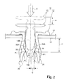
Fig. 3 is a side cross-sectional view showing a state wherein the fastener is inserted into attachment holes of a fastening member and a fastened member according to one embodiment of the present invention. -
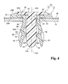
Fig. 4 is a side cross-sectional view showing a state wherein the fastening member and the fastened member are fastened by the fastener according to one embodiment of the present invention. -
Fig. 5 is a perspective view showing a grommet of the fastener according to one embodiment of the present invention. -
Fig. 6 is a front view showing the grommet of the fastener viewed from an end side in a shaft direction according to one embodiment of the present invention. -
Fig. 7 is a side view showing a pin of the fastener whose half is in a cross section according to one embodiment of the present invention. -
Fig. 8 is a front view showing the pin of the fastener viewed from an end side in a shaft direction according to one embodiment of the present invention. -
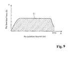
Fig. 9 is a graph showing a relationship between a moving distance of the pin and an insertion force of the pin in the fastener according to one embodiment of the present invention. - Next, one embodiment of a fastener of the present invention will be explained according to
Fig. 1 to Fig. 9 . - Incidentally, in figures, the same symbols are assigned to members (structure elements) having the same or corresponding functions, and their explanations are arbitrarily omitted.
- As shown in
Fig. 3 andFig. 4 , afastener 10 of the present embodiment comprises a grommet 12 (a first member) as the first member, and a pin 14 (a second member) as the second member so as to become a so-called push-and-rivet-type two-piece clip. Then, by thefastener 10, for example, a fastenedmember 18 such as an interior part and the like can be fastened to a fasteningmember 16 such as a panel part of an automobile and the like. - As shown in
Fig. 5 , in thegrommet 12, there is formed aflange portion 26 having approximately a circular disc shape in one end portion in a shaft direction. An outer diameter of theflange portion 26 is larger than each hole diameter of anattachment hole 20 formed in thefastening member 16, and anattachment hole 22 formed in the fastened member 18 (seeFig. 3 ). Also, in alower face 26A of theflange portion 26, there is formed aleg portion 28 extending downward (a downward direction inFig. 5 ). Inside theleg portion 28 of thegrommet 12, there is formed a pin insertion hole 32 (an insertion hole) as the insertion hole opened at anupper face 26B of theflange portion 26. Moreover, theleg portion 28 is provided with fourleg pieces 34. - As shown in
Fig. 6 , eachleg piece 34 of theleg portion 28 of thegrommet 12 is divided around a shaft line by two shaft flat surfaces of thegrommet 12 which are mutually orthogonal. Also,slits 40 having a predetermined width are formed between therespective leg pieces 34 next to each other, and in thelower face 26A of theflange portion 26, there are formedgrooves 30 along an outer circumferential portion of therespective leg pieces 34. - As shown in
Fig. 4 , a vicinity of a base portion of eachleg piece 34 of thegrommet 12 becomes ahinge portion 36 when eachleg piece 34 opens. - As shown in
Fig. 3 , thepin insertion hole 32 extends inside theleg portion 28 of thegrommet 12, and there is formed abottom portion 32A of thepin insertion hole 32 having approximately a bowl shape. Also, at positions having equal distances from thelower face 26A of theflange portion 26 inside therespective leg pieces 34 in thegrommet 12, there are formed guidedportions 42 to protrude toward ashaft line 12A of thegrommet 12. - As shown in
Fig. 7 , in one end in a shaft direction of thepin 14, there is formed ahead portion 50 having approximately a circular disc shape. An outer diameter of thehead portion 50 of thepin 14 is larger than an inner diameter of thepin insertion hole 32 opened at theflange portion 26 of the grommet 12 (seeFig. 5 ). Also, in alower face 50A of thehead portion 50, there is formed ashaft portion 52 extending downward (a downward direction inFig. 7 ). - In an end side (a lower side in
Fig. 7 ) of theshaft portion 52 in thepin 14, there is formed aguide portion 56. Also, on a base portion side of theshaft portion 52, there is formed abase portion 58 extending from thelower face 50A of thehead portion 50. Theguide portion 56 and thebase portion 58 are provided in the same straight line through anintermediate portion 59 formed approximately in a column shape. An outer diameter of theintermediate portion 59 is smaller than outer diameters of both alower end edge 58A of thebase portion 58 and anupper end edge 56A of theguide portion 56. Then, theupper end edge 56A of theguide portion 56 is formed along a circumferential direction of thepin 14. - Incidentally, as shown in
Fig. 4 , when thepin 14 is completely inserted into thegrommet 12, and a pull-in force is sufficiently enhanced, the guidedportion 42 of theleg piece 34 of thegrommet 12 is engaged with theupper end edge 56A of theguide portion 56 of thepin 14. - As shown in
Fig. 1 , an end portion of thepin 14 is formed in a circular truncated cone shape, and anend 14A has a flat surface orthogonal to ashaft line 14B of thepin 14. Also, theguide portion 56 of thepin 14 has a curved surface having a tangent angle (inclination angle) θ changing relative to theshaft line 14B at a contact point P1 with the guidedportion 42 from an outer circumferential edge of theend 14A of thepin 14 toward theupper end edge 56A. Thereby, when Young's modulus of theleg piece 34 of theleg portion 28 of thegrommet 12 is presumed to be constant, and a frictional force between thegrommet 12 and thepin 14 at the contact point P1 is presumed to be 0, an insertion force S is held approximately constant. - More specifically, as shown in
Fig. 2 , in a case wherein thepin 14 is pressed into thegrommet 12 for a predetermined volume as shown by solid lines from a position shown by two-dot chain lines, an opening volume (a deflection volume) of theleg piece 34 of thegrommet 12 at the contact point P1 with the guidedportion 42 of theguide portion 56 is V. Also, as shown inFig. 1 , the tangent angle relative to theshaft line 14B at the contact point P1 is θ. Then, when the Young's modulus of theleg piece 34 of theleg portion 28 of thegrommet 12 is presumed to be constant, and the frictional force between thegrommet 12 and thepin 14 at the contact point P1 is presumed to be 0, a relationship of V sin θ = constant (H) is established at the arbitrary point P1 on acurved surface 56B of theguide portion 56. - Incidentally, if a value of H is reduced, a length Y (see
Fig. 1 ) of theguide portion 56 of thepin 14 increases, so that the value of H is determined in view of the length Y of theguide portion 56 of thepin 14. - More specifically, as shown in
Fig. 1 , if E is the Young's modulus of thegrommet 12, I is a second moment of area for thegrommet 12, and L is a deflection length (seeFig. 2 ), a reaction force F from the guidedportion 42 of theleg piece 34 of thegrommet 12 vertically acted on the curved surface of theguide portion 56 is:
- Incidentally, the reference symbol "m" in
Fig. 2 represents a moving distance of thepin 14. - Here, although the Young's modulus E is a variable due to a distortion, if the Young's modulus E is presumed to be constant, 3 · E · I / L3 becomes a constant K (F = K · V), and as for the reaction force F, the opening volume of the
leg piece 34 of thegrommet 12 is proportional to V. - Also, as shown in
Fig. 1 , if µ is a friction coefficient, a component Fy in a Y direction of the reaction force F, and a component My in the Y direction of a frictional force M along the curved surface acted between theguide portion 56 and the guidedportion 42 are:

- As a result, the insertion force S of the pin is S = Fy + My = F · sin θ + µF · cos θ.
- Here, if the component My in the Y direction of the frictional force M is disregarded, the insertion force S of the
pin 14 is S = K · V · sin θ, and the insertion force S is proportional to V · sin θ. Consequently, the curved surface of theguide portion 56 can be the curved surface having the tangent angle θ such that the insertion force S becomes constant relative to a change of the opening volume (the deflection volume) V of theleg piece 34 at each contact point P1 from an end side toward a base portion side. - As shown in
Fig. 7 and Fig. 8 , in thepin 14, there are formed four pieces ofribs 60 at equal intervals provided on a shaft flat surface around a shaft line of thebase portion 58. Then, in thefastener 10, eachrib 60 of thepin 14 is inserted into each slit 40 formed between theleg pieces 34 next to each other in thegrommet 12, so that thegrommet 12 is rotated to be locked relative to thepin 14. Incidentally, as shown inFig. 3 , thefastener 10 is shipped from a factory in a state wherein thegrommet 12 and thepin 14 are assembled, and is mounted into theattachment hole 20 of thefastening member 16 and theattachment hole 22 of the fastenedmember 18. - Next, an operation and an effect of the present embodiment will be explained.
- As shown in
Fig. 3 , thefastener 10 of the present embodiment is inserted into theattachment hole 20 and theattachment hole 22 in a state wherein the fastenedmember 18 is overlapped with thefastening member 16, and theattachment hole 22 is matched to theattachment hole 20. After that, as shown inFig. 4 , thepin 14 is pressed into thegrommet 12, so that theguide portion 56 formed on the end side of thepin 14 contacts with the guidedportion 42 of thegrommet 12, and eachleg piece 34 of theleg portion 28 of thegrommet 12 bends and is expanded. Then, when the guidedportion 42 of eachleg piece 34 is engaged with theupper end edge 56A of theguide portion 56 of thepin 14, the pull-in force (an axial force) is generated in thefastener 10 by the reaction force of a deflection of thegrommet 12, so that thefastening member 16 and the fastenedmember 18 are fastened. - At that time, as shown in
Fig. 1 andFig. 2 , in thefastener 10 of the present embodiment, theguide portion 56 of thepin 14 has the curved surface having the tangent angle θ changing relative to theshaft line 14B at each contact point P1 with the guidedportion 42 from an outer circumferential portion of theend 14A of thepin 14 toward theupper end edge 56A. Also, the insertion force S into thegrommet 12 of thepin 14 is held approximately constant. - Namely, the Young's modulus of each
leg piece 34 of theleg portion 28 is constant, and due to a reduction of the Young's modulus, an increase of the frictional force is negated in some measure, so that if the frictional force at the contact point P1 is presumed to be 0, and the opening volume of theleg piece 34 of thegrommet 12 at the contact point P1 with the guidedportion 42 of theguide portion 56 is V, and the tangent angle relative to theshaft line 14B of thepin 14 at the contact point P1 is θ, the relationship of V sin θ = constant is established at the arbitrary point P1 on thecurved surface 56B of theguide portion 56. - Therefore, as shown in
Fig. 9 , when thepin 14 is pressed into thegrommet 12, and an insertion volume m is increased, an increase of the insertion force S into thegrommet 12 of thepin 14 is controlled so as to become approximately constant. Consequently, in a second half of an insertion into thegrommet 12 of thepin 14, the increase of the insertion force can be controlled so as to improve operability. - As a result, in the
fastener 10 of the present embodiment, thepin 14 is smoothly inserted into thegrommet 12 without rapidly changing the insertion force S into thegrommet 12 of thepin 14, and the insertion force in the second half of the insertion of thepin 14 into thegrommet 12 does not increase, so that an operator does not have to feel long until the insertion is completed. - Incidentally, as shown by diagonal lines in
Fig. 9 , the pull-in force of thefastener 10 of the present embodiment is shown by an area of a portion surrounded by a curved line C1, an X-axis, and X = m showing a relationship between the insertion volume m of thepin 14 and the insertion force S of thepin 14. As a result, by increasing the insertion volume m of thepin 14, after ensuring a sufficient pull-in force, the increase of the insertion force in the second half of the insertion of thepin 14 is controlled. - Also, in the
fastener 10 of the present embodiment, the length Y (seeFig. 1 ) of theguide portion 56 of thepin 14 is determined by the value of V sin θ = constant (H). Also, V sin θ can approximate the insertion force S. Consequently, a comparison of a value of each V sin θ = constant (H) in a plurality offasteners 10 can provide an indication of the insertion force S of thepin 14 in eachfastener 10. As a result, thefastener 10, in which the insertion force S of thepin 14 and the length Y of theguide portion 56 of thepin 14 are predicted, can be designed. - In the above, specific embodiments of the present invention have been explained in detail. However, the present invention is not limited to the embodiments described hereinabove, and it is obvious for a person skilled in the art that other various embodiments can be carried out within a range of the present invention. For example, in the embodiments described hereinabove, the
fastener 10 comprising thegrommet 12 as the first member and thepin 14 as the second member has been explained. However, the fastener of the present invention can be applied to other fasteners in which the guide portion of the second member contacts with the guided portion of the first member by pressing the second member into the first member so that the leg portion of the first member bends and is expanded. - Also, in the embodiments, the Young's modulus of the
leg piece 34 of theleg portion 28 of thegrommet 12 is presumed to be constant, and the frictional force at the contact point P1 is presumed to be 0. In place of that, the increase of the frictional force and the reduction of the Young's modulus associated with the increase of the insertion volume of thepin 14 may be considered. Incidentally, the increase of the frictional force and the reduction of the Young's modulus negate each other in some measure, and change by a material of thefastener 10 or a thickness of thefastening member 16, so that a change of the Young's modulus of theleg piece 34 and weighting of the frictional force may be added.
Claims (2)
- A fastener, comprising:a first member including a flange portion, and a leg portion extending from the flange portion, forming an insertion hole opening at the flange portion, divided around a shaft line, and formed with a guided portion in an inner circumferential portion of the insertion hole; anda second member having a guide portion from a vicinity of an end toward a base direction, and pressed into the insertion hole of the first member so as to contact the guide portion with the guided portion and to expand the leg portion,wherein the guide portion has a curved surface having a tangent angle changing relative to a shaft line at a contact point with the guided portion from an end side toward a base portion side, and an insertion force into the first member at each contact point is held approximately constant.
- A fastener according to claim 2, wherein when Young's modulus of the leg portion is presumed to be constant, and a frictional force at the contact point is presumed to be 0, and an opening volume of the leg portion at an arbitrary point on the curved surface is V and the tangent angle is θ, a relationship of V sin θ = constant is established at the arbitrary point on the curved surface.
Applications Claiming Priority (2)
| Application Number | Priority Date | Filing Date | Title |
|---|---|---|---|
| JP2011203340A JP5901195B2 (en) | 2011-09-16 | 2011-09-16 | Fastener |
| PCT/JP2012/073357 WO2013039115A1 (en) | 2011-09-16 | 2012-09-12 | Fastener |
Publications (3)
| Publication Number | Publication Date |
|---|---|
| EP2757274A1 true EP2757274A1 (en) | 2014-07-23 |
| EP2757274A4 EP2757274A4 (en) | 2015-07-01 |
| EP2757274B1 EP2757274B1 (en) | 2017-08-09 |
Family
ID=47883340
Family Applications (1)
| Application Number | Title | Priority Date | Filing Date |
|---|---|---|---|
| EP12832135.3A Active EP2757274B1 (en) | 2011-09-16 | 2012-09-12 | Fastener |
Country Status (9)
| Country | Link |
|---|---|
| US (1) | US9341210B2 (en) |
| EP (1) | EP2757274B1 (en) |
| JP (1) | JP5901195B2 (en) |
| KR (1) | KR101880329B1 (en) |
| CN (1) | CN103827517B (en) |
| BR (1) | BR112014006325B1 (en) |
| MX (1) | MX352561B (en) |
| RU (1) | RU2563766C1 (en) |
| WO (1) | WO2013039115A1 (en) |
Families Citing this family (12)
| Publication number | Priority date | Publication date | Assignee | Title |
|---|---|---|---|---|
| US9528540B2 (en) * | 2014-08-12 | 2016-12-27 | Newfrey Llc | Insertion-locking pin and grommet and related methods |
| US9222749B1 (en) * | 2014-12-03 | 2015-12-29 | Magpul Industries, Corp. | Cover kit for a firearm handguard |
| JP6281514B2 (en) | 2015-03-26 | 2018-02-21 | トヨタ自動車株式会社 | Mounting clip and attachment mounting structure using the same |
| JP6229687B2 (en) * | 2015-03-26 | 2017-11-15 | トヨタ自動車株式会社 | Mounting clip and attachment mounting structure using the same |
| KR102295273B1 (en) * | 2018-07-06 | 2021-08-27 | 일리노이즈 툴 워크스 인코포레이티드 | Fastener assembly |
| US11592050B2 (en) | 2019-01-09 | 2023-02-28 | Illinois Tool Works Inc. | Apparatus for a captured fastener assembly with expanding grommet |
| DE102020110407B4 (en) * | 2020-04-16 | 2026-04-23 | Illinois Tool Works Inc. | Fastening device for attaching a component to a supporting component |
| WO2022114297A1 (en) * | 2020-11-27 | 2022-06-02 | 유한회사 지에스코리아 농업회사법인 | Flowerpot to which fastening members are fastened |
| JP7663884B2 (en) * | 2021-04-30 | 2025-04-17 | 国立研究開発法人宇宙航空研究開発機構 | Connecting material |
| US20220373015A1 (en) * | 2021-05-19 | 2022-11-24 | Rudor M. Teich | Fixed Engagement Anchor |
| CN115653981A (en) * | 2022-09-27 | 2023-01-31 | 上海宝鹿车业有限公司 | Automobile ornament mounting buckle |
| CN118793679A (en) * | 2023-04-13 | 2024-10-18 | 伊利诺斯工具制品有限公司 | Fastening piece |
Family Cites Families (13)
| Publication number | Priority date | Publication date | Assignee | Title |
|---|---|---|---|---|
| JPH0417859Y2 (en) * | 1987-09-14 | 1992-04-21 | ||
| JP2578069Y2 (en) * | 1991-03-11 | 1998-08-06 | 株式会社 ニフコ | Grommet |
| JP4201217B2 (en) * | 1998-03-23 | 2008-12-24 | 株式会社ニフコ | clip |
| JP3914710B2 (en) * | 2001-01-15 | 2007-05-16 | 株式会社ニフコ | Fastener |
| JP2005337312A (en) * | 2004-05-25 | 2005-12-08 | Piolax Inc | Stop |
| DE102004036621B4 (en) * | 2004-07-28 | 2007-04-26 | A. Raymond Et Cie | Spreizniet |
| JP4679871B2 (en) | 2004-10-08 | 2011-05-11 | トヨタ自動車株式会社 | Fastener |
| JP4520920B2 (en) * | 2005-08-22 | 2010-08-11 | 株式会社ニフコ | clip |
| JP5145129B2 (en) * | 2008-06-24 | 2013-02-13 | 株式会社ニフコ | clip |
| DE202008012698U1 (en) * | 2008-09-24 | 2009-02-05 | Trw Automotive Electronics & Components Gmbh | fastening device |
| JP5336284B2 (en) * | 2009-07-15 | 2013-11-06 | 株式会社ニフコ | 2 piece clip |
| JP5307053B2 (en) * | 2010-03-03 | 2013-10-02 | 株式会社ニフコ | Grommet |
| JP5701593B2 (en) * | 2010-12-24 | 2015-04-15 | 株式会社ニフコ | 2 piece clip |
-
2011
- 2011-09-16 JP JP2011203340A patent/JP5901195B2/en active Active
-
2012
- 2012-09-12 RU RU2014113431/12A patent/RU2563766C1/en not_active IP Right Cessation
- 2012-09-12 BR BR112014006325-7A patent/BR112014006325B1/en not_active IP Right Cessation
- 2012-09-12 US US14/344,717 patent/US9341210B2/en active Active
- 2012-09-12 WO PCT/JP2012/073357 patent/WO2013039115A1/en not_active Ceased
- 2012-09-12 MX MX2014003233A patent/MX352561B/en active IP Right Grant
- 2012-09-12 KR KR1020147007891A patent/KR101880329B1/en active Active
- 2012-09-12 CN CN201280044866.1A patent/CN103827517B/en active Active
- 2012-09-12 EP EP12832135.3A patent/EP2757274B1/en active Active
Also Published As
| Publication number | Publication date |
|---|---|
| BR112014006325B1 (en) | 2020-07-07 |
| BR112014006325A2 (en) | 2017-04-11 |
| JP5901195B2 (en) | 2016-04-06 |
| EP2757274A4 (en) | 2015-07-01 |
| MX352561B (en) | 2017-11-29 |
| KR20140061465A (en) | 2014-05-21 |
| MX2014003233A (en) | 2015-02-05 |
| CN103827517A (en) | 2014-05-28 |
| EP2757274B1 (en) | 2017-08-09 |
| KR101880329B1 (en) | 2018-07-19 |
| RU2563766C1 (en) | 2015-09-20 |
| CN103827517B (en) | 2016-03-30 |
| WO2013039115A1 (en) | 2013-03-21 |
| US9341210B2 (en) | 2016-05-17 |
| US20140341674A1 (en) | 2014-11-20 |
| JP2013064444A (en) | 2013-04-11 |
Similar Documents
| Publication | Publication Date | Title |
|---|---|---|
| EP2757274A1 (en) | Fastener | |
| JP4649120B2 (en) | clip | |
| US8613414B2 (en) | Fastening clip and associated fastener | |
| EP1876361B1 (en) | Clip | |
| US9982700B2 (en) | Fastener | |
| JP6255033B2 (en) | Stop | |
| JP5128546B2 (en) | Fastener | |
| WO2007122834A1 (en) | Article installation device | |
| EP3187375B1 (en) | Tether clip and structure for mounting tether clip to pillar garnish | |
| EP3135925A1 (en) | Rivet | |
| EP3364051B1 (en) | A method for mounting a sheet like member onto a mounted member by utilizing a fastening device and mounting structure | |
| JP2020153517A (en) | Rivet-type fastener | |
| US20010002965A1 (en) | Structure for mounting to steering wheel | |
| JP6196096B2 (en) | Clip mounting seat for interior parts or exterior parts | |
| JP2010007808A (en) | Clip | |
| US20190177034A1 (en) | Can lid | |
| JP5980582B2 (en) | Fastener | |
| JP4712672B2 (en) | clip | |
| JP5859919B2 (en) | Clip and fastener with the clip | |
| JP4679871B2 (en) | Fastener | |
| JP6192479B2 (en) | Airbag device for passenger seat | |
| WO2014104356A1 (en) | Clip | |
| JP7280813B2 (en) | Fastener | |
| JP2017046441A (en) | Clamp and electric wire with clamp | |
| JP2018135010A (en) | Interior parts for vehicles |
Legal Events
| Date | Code | Title | Description |
|---|---|---|---|
| PUAI | Public reference made under article 153(3) epc to a published international application that has entered the european phase |
Free format text: ORIGINAL CODE: 0009012 |
|
| 17P | Request for examination filed |
Effective date: 20140314 |
|
| AK | Designated contracting states |
Kind code of ref document: A1 Designated state(s): AL AT BE BG CH CY CZ DE DK EE ES FI FR GB GR HR HU IE IS IT LI LT LU LV MC MK MT NL NO PL PT RO RS SE SI SK SM TR |
|
| DAX | Request for extension of the european patent (deleted) | ||
| RIC1 | Information provided on ipc code assigned before grant |
Ipc: F16B 19/10 20060101AFI20150513BHEP Ipc: F16B 5/00 20060101ALI20150513BHEP |
|
| RA4 | Supplementary search report drawn up and despatched (corrected) |
Effective date: 20150601 |
|
| RIC1 | Information provided on ipc code assigned before grant |
Ipc: F16B 19/10 20060101AFI20150522BHEP Ipc: F16B 5/00 20060101ALI20150522BHEP |
|
| 17Q | First examination report despatched |
Effective date: 20160622 |
|
| GRAP | Despatch of communication of intention to grant a patent |
Free format text: ORIGINAL CODE: EPIDOSNIGR1 |
|
| INTG | Intention to grant announced |
Effective date: 20170314 |
|
| GRAS | Grant fee paid |
Free format text: ORIGINAL CODE: EPIDOSNIGR3 |
|
| GRAA | (expected) grant |
Free format text: ORIGINAL CODE: 0009210 |
|
| AK | Designated contracting states |
Kind code of ref document: B1 Designated state(s): AL AT BE BG CH CY CZ DE DK EE ES FI FR GB GR HR HU IE IS IT LI LT LU LV MC MK MT NL NO PL PT RO RS SE SI SK SM TR |
|
| RAP1 | Party data changed (applicant data changed or rights of an application transferred) |
Owner name: NIFCO INC. |
|
| REG | Reference to a national code |
Ref country code: GB Ref legal event code: FG4D |
|
| RIN1 | Information on inventor provided before grant (corrected) |
Inventor name: HIRANO, YOICHI |
|
| REG | Reference to a national code |
Ref country code: CH Ref legal event code: EP Ref country code: AT Ref legal event code: REF Ref document number: 917189 Country of ref document: AT Kind code of ref document: T Effective date: 20170815 |
|
| REG | Reference to a national code |
Ref country code: IE Ref legal event code: FG4D |
|
| REG | Reference to a national code |
Ref country code: DE Ref legal event code: R096 Ref document number: 602012035793 Country of ref document: DE Ref country code: FR Ref legal event code: PLFP Year of fee payment: 6 |
|
| REG | Reference to a national code |
Ref country code: NL Ref legal event code: MP Effective date: 20170809 |
|
| REG | Reference to a national code |
Ref country code: LT Ref legal event code: MG4D |
|
| REG | Reference to a national code |
Ref country code: AT Ref legal event code: MK05 Ref document number: 917189 Country of ref document: AT Kind code of ref document: T Effective date: 20170809 |
|
| PG25 | Lapsed in a contracting state [announced via postgrant information from national office to epo] |
Ref country code: NL Free format text: LAPSE BECAUSE OF FAILURE TO SUBMIT A TRANSLATION OF THE DESCRIPTION OR TO PAY THE FEE WITHIN THE PRESCRIBED TIME-LIMIT Effective date: 20170809 Ref country code: FI Free format text: LAPSE BECAUSE OF FAILURE TO SUBMIT A TRANSLATION OF THE DESCRIPTION OR TO PAY THE FEE WITHIN THE PRESCRIBED TIME-LIMIT Effective date: 20170809 Ref country code: NO Free format text: LAPSE BECAUSE OF FAILURE TO SUBMIT A TRANSLATION OF THE DESCRIPTION OR TO PAY THE FEE WITHIN THE PRESCRIBED TIME-LIMIT Effective date: 20171109 Ref country code: AT Free format text: LAPSE BECAUSE OF FAILURE TO SUBMIT A TRANSLATION OF THE DESCRIPTION OR TO PAY THE FEE WITHIN THE PRESCRIBED TIME-LIMIT Effective date: 20170809 Ref country code: SE Free format text: LAPSE BECAUSE OF FAILURE TO SUBMIT A TRANSLATION OF THE DESCRIPTION OR TO PAY THE FEE WITHIN THE PRESCRIBED TIME-LIMIT Effective date: 20170809 Ref country code: LT Free format text: LAPSE BECAUSE OF FAILURE TO SUBMIT A TRANSLATION OF THE DESCRIPTION OR TO PAY THE FEE WITHIN THE PRESCRIBED TIME-LIMIT Effective date: 20170809 Ref country code: HR Free format text: LAPSE BECAUSE OF FAILURE TO SUBMIT A TRANSLATION OF THE DESCRIPTION OR TO PAY THE FEE WITHIN THE PRESCRIBED TIME-LIMIT Effective date: 20170809 |
|
| PG25 | Lapsed in a contracting state [announced via postgrant information from national office to epo] |
Ref country code: RS Free format text: LAPSE BECAUSE OF FAILURE TO SUBMIT A TRANSLATION OF THE DESCRIPTION OR TO PAY THE FEE WITHIN THE PRESCRIBED TIME-LIMIT Effective date: 20170809 Ref country code: BG Free format text: LAPSE BECAUSE OF FAILURE TO SUBMIT A TRANSLATION OF THE DESCRIPTION OR TO PAY THE FEE WITHIN THE PRESCRIBED TIME-LIMIT Effective date: 20171109 Ref country code: PL Free format text: LAPSE BECAUSE OF FAILURE TO SUBMIT A TRANSLATION OF THE DESCRIPTION OR TO PAY THE FEE WITHIN THE PRESCRIBED TIME-LIMIT Effective date: 20170809 Ref country code: ES Free format text: LAPSE BECAUSE OF FAILURE TO SUBMIT A TRANSLATION OF THE DESCRIPTION OR TO PAY THE FEE WITHIN THE PRESCRIBED TIME-LIMIT Effective date: 20170809 Ref country code: GR Free format text: LAPSE BECAUSE OF FAILURE TO SUBMIT A TRANSLATION OF THE DESCRIPTION OR TO PAY THE FEE WITHIN THE PRESCRIBED TIME-LIMIT Effective date: 20171110 Ref country code: LV Free format text: LAPSE BECAUSE OF FAILURE TO SUBMIT A TRANSLATION OF THE DESCRIPTION OR TO PAY THE FEE WITHIN THE PRESCRIBED TIME-LIMIT Effective date: 20170809 Ref country code: IS Free format text: LAPSE BECAUSE OF FAILURE TO SUBMIT A TRANSLATION OF THE DESCRIPTION OR TO PAY THE FEE WITHIN THE PRESCRIBED TIME-LIMIT Effective date: 20171209 |
|
| PG25 | Lapsed in a contracting state [announced via postgrant information from national office to epo] |
Ref country code: DK Free format text: LAPSE BECAUSE OF FAILURE TO SUBMIT A TRANSLATION OF THE DESCRIPTION OR TO PAY THE FEE WITHIN THE PRESCRIBED TIME-LIMIT Effective date: 20170809 Ref country code: CZ Free format text: LAPSE BECAUSE OF FAILURE TO SUBMIT A TRANSLATION OF THE DESCRIPTION OR TO PAY THE FEE WITHIN THE PRESCRIBED TIME-LIMIT Effective date: 20170809 Ref country code: RO Free format text: LAPSE BECAUSE OF FAILURE TO SUBMIT A TRANSLATION OF THE DESCRIPTION OR TO PAY THE FEE WITHIN THE PRESCRIBED TIME-LIMIT Effective date: 20170809 |
|
| REG | Reference to a national code |
Ref country code: CH Ref legal event code: PL |
|
| REG | Reference to a national code |
Ref country code: DE Ref legal event code: R097 Ref document number: 602012035793 Country of ref document: DE |
|
| PG25 | Lapsed in a contracting state [announced via postgrant information from national office to epo] |
Ref country code: SK Free format text: LAPSE BECAUSE OF FAILURE TO SUBMIT A TRANSLATION OF THE DESCRIPTION OR TO PAY THE FEE WITHIN THE PRESCRIBED TIME-LIMIT Effective date: 20170809 Ref country code: EE Free format text: LAPSE BECAUSE OF FAILURE TO SUBMIT A TRANSLATION OF THE DESCRIPTION OR TO PAY THE FEE WITHIN THE PRESCRIBED TIME-LIMIT Effective date: 20170809 Ref country code: IT Free format text: LAPSE BECAUSE OF FAILURE TO SUBMIT A TRANSLATION OF THE DESCRIPTION OR TO PAY THE FEE WITHIN THE PRESCRIBED TIME-LIMIT Effective date: 20170809 Ref country code: MC Free format text: LAPSE BECAUSE OF FAILURE TO SUBMIT A TRANSLATION OF THE DESCRIPTION OR TO PAY THE FEE WITHIN THE PRESCRIBED TIME-LIMIT Effective date: 20170809 Ref country code: SM Free format text: LAPSE BECAUSE OF FAILURE TO SUBMIT A TRANSLATION OF THE DESCRIPTION OR TO PAY THE FEE WITHIN THE PRESCRIBED TIME-LIMIT Effective date: 20170809 |
|
| PLBE | No opposition filed within time limit |
Free format text: ORIGINAL CODE: 0009261 |
|
| STAA | Information on the status of an ep patent application or granted ep patent |
Free format text: STATUS: NO OPPOSITION FILED WITHIN TIME LIMIT |
|
| REG | Reference to a national code |
Ref country code: IE Ref legal event code: MM4A |
|
| REG | Reference to a national code |
Ref country code: BE Ref legal event code: MM Effective date: 20170930 |
|
| PG25 | Lapsed in a contracting state [announced via postgrant information from national office to epo] |
Ref country code: LU Free format text: LAPSE BECAUSE OF NON-PAYMENT OF DUE FEES Effective date: 20170912 |
|
| 26N | No opposition filed |
Effective date: 20180511 |
|
| PG25 | Lapsed in a contracting state [announced via postgrant information from national office to epo] |
Ref country code: IE Free format text: LAPSE BECAUSE OF NON-PAYMENT OF DUE FEES Effective date: 20170912 Ref country code: CH Free format text: LAPSE BECAUSE OF NON-PAYMENT OF DUE FEES Effective date: 20170930 Ref country code: LI Free format text: LAPSE BECAUSE OF NON-PAYMENT OF DUE FEES Effective date: 20170930 |
|
| REG | Reference to a national code |
Ref country code: FR Ref legal event code: PLFP Year of fee payment: 7 |
|
| PG25 | Lapsed in a contracting state [announced via postgrant information from national office to epo] |
Ref country code: BE Free format text: LAPSE BECAUSE OF NON-PAYMENT OF DUE FEES Effective date: 20170930 Ref country code: SI Free format text: LAPSE BECAUSE OF FAILURE TO SUBMIT A TRANSLATION OF THE DESCRIPTION OR TO PAY THE FEE WITHIN THE PRESCRIBED TIME-LIMIT Effective date: 20170809 |
|
| PG25 | Lapsed in a contracting state [announced via postgrant information from national office to epo] |
Ref country code: MT Free format text: LAPSE BECAUSE OF NON-PAYMENT OF DUE FEES Effective date: 20170912 |
|
| PG25 | Lapsed in a contracting state [announced via postgrant information from national office to epo] |
Ref country code: HU Free format text: LAPSE BECAUSE OF FAILURE TO SUBMIT A TRANSLATION OF THE DESCRIPTION OR TO PAY THE FEE WITHIN THE PRESCRIBED TIME-LIMIT; INVALID AB INITIO Effective date: 20120912 |
|
| PG25 | Lapsed in a contracting state [announced via postgrant information from national office to epo] |
Ref country code: CY Free format text: LAPSE BECAUSE OF NON-PAYMENT OF DUE FEES Effective date: 20170809 |
|
| PGFP | Annual fee paid to national office [announced via postgrant information from national office to epo] |
Ref country code: FR Payment date: 20190815 Year of fee payment: 8 |
|
| PG25 | Lapsed in a contracting state [announced via postgrant information from national office to epo] |
Ref country code: MK Free format text: LAPSE BECAUSE OF FAILURE TO SUBMIT A TRANSLATION OF THE DESCRIPTION OR TO PAY THE FEE WITHIN THE PRESCRIBED TIME-LIMIT Effective date: 20170809 |
|
| PGFP | Annual fee paid to national office [announced via postgrant information from national office to epo] |
Ref country code: GB Payment date: 20190912 Year of fee payment: 8 |
|
| PG25 | Lapsed in a contracting state [announced via postgrant information from national office to epo] |
Ref country code: TR Free format text: LAPSE BECAUSE OF FAILURE TO SUBMIT A TRANSLATION OF THE DESCRIPTION OR TO PAY THE FEE WITHIN THE PRESCRIBED TIME-LIMIT Effective date: 20170809 |
|
| PG25 | Lapsed in a contracting state [announced via postgrant information from national office to epo] |
Ref country code: PT Free format text: LAPSE BECAUSE OF FAILURE TO SUBMIT A TRANSLATION OF THE DESCRIPTION OR TO PAY THE FEE WITHIN THE PRESCRIBED TIME-LIMIT Effective date: 20170809 |
|
| PG25 | Lapsed in a contracting state [announced via postgrant information from national office to epo] |
Ref country code: AL Free format text: LAPSE BECAUSE OF FAILURE TO SUBMIT A TRANSLATION OF THE DESCRIPTION OR TO PAY THE FEE WITHIN THE PRESCRIBED TIME-LIMIT Effective date: 20170809 |
|
| GBPC | Gb: european patent ceased through non-payment of renewal fee |
Effective date: 20200912 |
|
| PG25 | Lapsed in a contracting state [announced via postgrant information from national office to epo] |
Ref country code: FR Free format text: LAPSE BECAUSE OF NON-PAYMENT OF DUE FEES Effective date: 20200930 |
|
| PG25 | Lapsed in a contracting state [announced via postgrant information from national office to epo] |
Ref country code: GB Free format text: LAPSE BECAUSE OF NON-PAYMENT OF DUE FEES Effective date: 20200912 |
|
| PGFP | Annual fee paid to national office [announced via postgrant information from national office to epo] |
Ref country code: DE Payment date: 20250730 Year of fee payment: 14 |