EP2757254B1 - Wind turbine blade - Google Patents
Wind turbine blade Download PDFInfo
- Publication number
- EP2757254B1 EP2757254B1 EP13382022.5A EP13382022A EP2757254B1 EP 2757254 B1 EP2757254 B1 EP 2757254B1 EP 13382022 A EP13382022 A EP 13382022A EP 2757254 B1 EP2757254 B1 EP 2757254B1
- Authority
- EP
- European Patent Office
- Prior art keywords
- blade
- actuators
- wind turbine
- trailing edge
- actuator
- Prior art date
- Legal status (The legal status is an assumption and is not a legal conclusion. Google has not performed a legal analysis and makes no representation as to the accuracy of the status listed.)
- Active
Links
- 239000000463 material Substances 0.000 claims description 25
- 238000011144 upstream manufacturing Methods 0.000 claims description 12
- 230000004913 activation Effects 0.000 claims description 5
- 238000000034 method Methods 0.000 claims description 5
- 230000003213 activating effect Effects 0.000 claims description 2
- 230000007423 decrease Effects 0.000 description 3
- 230000000694 effects Effects 0.000 description 3
- 239000002131 composite material Substances 0.000 description 2
- 238000010276 construction Methods 0.000 description 2
- 230000009471 action Effects 0.000 description 1
- 238000005452 bending Methods 0.000 description 1
- 230000008859 change Effects 0.000 description 1
- 230000002301 combined effect Effects 0.000 description 1
- 230000003247 decreasing effect Effects 0.000 description 1
- 230000005684 electric field Effects 0.000 description 1
- 230000005611 electricity Effects 0.000 description 1
- 239000003562 lightweight material Substances 0.000 description 1
- 238000004519 manufacturing process Methods 0.000 description 1
- 230000004048 modification Effects 0.000 description 1
- 238000012986 modification Methods 0.000 description 1
- 230000007935 neutral effect Effects 0.000 description 1
- 230000037311 normal skin Effects 0.000 description 1
- 238000000926 separation method Methods 0.000 description 1
- 239000002520 smart material Substances 0.000 description 1
Images


Classifications
-
- F—MECHANICAL ENGINEERING; LIGHTING; HEATING; WEAPONS; BLASTING
- F03—MACHINES OR ENGINES FOR LIQUIDS; WIND, SPRING, OR WEIGHT MOTORS; PRODUCING MECHANICAL POWER OR A REACTIVE PROPULSIVE THRUST, NOT OTHERWISE PROVIDED FOR
- F03D—WIND MOTORS
- F03D7/00—Controlling wind motors
- F03D7/02—Controlling wind motors the wind motors having rotation axis substantially parallel to the air flow entering the rotor
- F03D7/022—Adjusting aerodynamic properties of the blades
- F03D7/0236—Adjusting aerodynamic properties of the blades by changing the active surface of the wind engaging parts, e.g. reefing or furling
-
- F—MECHANICAL ENGINEERING; LIGHTING; HEATING; WEAPONS; BLASTING
- F03—MACHINES OR ENGINES FOR LIQUIDS; WIND, SPRING, OR WEIGHT MOTORS; PRODUCING MECHANICAL POWER OR A REACTIVE PROPULSIVE THRUST, NOT OTHERWISE PROVIDED FOR
- F03D—WIND MOTORS
- F03D7/00—Controlling wind motors
- F03D7/02—Controlling wind motors the wind motors having rotation axis substantially parallel to the air flow entering the rotor
- F03D7/022—Adjusting aerodynamic properties of the blades
- F03D7/0232—Adjusting aerodynamic properties of the blades with flaps or slats
-
- F—MECHANICAL ENGINEERING; LIGHTING; HEATING; WEAPONS; BLASTING
- F03—MACHINES OR ENGINES FOR LIQUIDS; WIND, SPRING, OR WEIGHT MOTORS; PRODUCING MECHANICAL POWER OR A REACTIVE PROPULSIVE THRUST, NOT OTHERWISE PROVIDED FOR
- F03D—WIND MOTORS
- F03D1/00—Wind motors with rotation axis substantially parallel to the air flow entering the rotor
- F03D1/06—Rotors
- F03D1/065—Rotors characterised by their construction elements
- F03D1/0675—Rotors characterised by their construction elements of the blades
-
- F—MECHANICAL ENGINEERING; LIGHTING; HEATING; WEAPONS; BLASTING
- F03—MACHINES OR ENGINES FOR LIQUIDS; WIND, SPRING, OR WEIGHT MOTORS; PRODUCING MECHANICAL POWER OR A REACTIVE PROPULSIVE THRUST, NOT OTHERWISE PROVIDED FOR
- F03D—WIND MOTORS
- F03D7/00—Controlling wind motors
- F03D7/02—Controlling wind motors the wind motors having rotation axis substantially parallel to the air flow entering the rotor
- F03D7/022—Adjusting aerodynamic properties of the blades
-
- F—MECHANICAL ENGINEERING; LIGHTING; HEATING; WEAPONS; BLASTING
- F03—MACHINES OR ENGINES FOR LIQUIDS; WIND, SPRING, OR WEIGHT MOTORS; PRODUCING MECHANICAL POWER OR A REACTIVE PROPULSIVE THRUST, NOT OTHERWISE PROVIDED FOR
- F03D—WIND MOTORS
- F03D7/00—Controlling wind motors
- F03D7/02—Controlling wind motors the wind motors having rotation axis substantially parallel to the air flow entering the rotor
- F03D7/0244—Controlling wind motors the wind motors having rotation axis substantially parallel to the air flow entering the rotor for braking
- F03D7/0252—Controlling wind motors the wind motors having rotation axis substantially parallel to the air flow entering the rotor for braking with aerodynamic drag devices on the blades
-
- F—MECHANICAL ENGINEERING; LIGHTING; HEATING; WEAPONS; BLASTING
- F03—MACHINES OR ENGINES FOR LIQUIDS; WIND, SPRING, OR WEIGHT MOTORS; PRODUCING MECHANICAL POWER OR A REACTIVE PROPULSIVE THRUST, NOT OTHERWISE PROVIDED FOR
- F03D—WIND MOTORS
- F03D7/00—Controlling wind motors
- F03D7/02—Controlling wind motors the wind motors having rotation axis substantially parallel to the air flow entering the rotor
- F03D7/04—Automatic control; Regulation
- F03D7/041—Automatic control; Regulation by means of a mechanical governor
-
- F—MECHANICAL ENGINEERING; LIGHTING; HEATING; WEAPONS; BLASTING
- F03—MACHINES OR ENGINES FOR LIQUIDS; WIND, SPRING, OR WEIGHT MOTORS; PRODUCING MECHANICAL POWER OR A REACTIVE PROPULSIVE THRUST, NOT OTHERWISE PROVIDED FOR
- F03D—WIND MOTORS
- F03D7/00—Controlling wind motors
- F03D7/02—Controlling wind motors the wind motors having rotation axis substantially parallel to the air flow entering the rotor
- F03D7/04—Automatic control; Regulation
- F03D7/042—Automatic control; Regulation by means of an electrical or electronic controller
-
- F—MECHANICAL ENGINEERING; LIGHTING; HEATING; WEAPONS; BLASTING
- F05—INDEXING SCHEMES RELATING TO ENGINES OR PUMPS IN VARIOUS SUBCLASSES OF CLASSES F01-F04
- F05B—INDEXING SCHEME RELATING TO WIND, SPRING, WEIGHT, INERTIA OR LIKE MOTORS, TO MACHINES OR ENGINES FOR LIQUIDS COVERED BY SUBCLASSES F03B, F03D AND F03G
- F05B2240/00—Components
- F05B2240/20—Rotors
- F05B2240/30—Characteristics of rotor blades, i.e. of any element transforming dynamic fluid energy to or from rotational energy and being attached to a rotor
- F05B2240/31—Characteristics of rotor blades, i.e. of any element transforming dynamic fluid energy to or from rotational energy and being attached to a rotor of changeable form or shape
- F05B2240/311—Characteristics of rotor blades, i.e. of any element transforming dynamic fluid energy to or from rotational energy and being attached to a rotor of changeable form or shape flexible or elastic
-
- F—MECHANICAL ENGINEERING; LIGHTING; HEATING; WEAPONS; BLASTING
- F05—INDEXING SCHEMES RELATING TO ENGINES OR PUMPS IN VARIOUS SUBCLASSES OF CLASSES F01-F04
- F05B—INDEXING SCHEME RELATING TO WIND, SPRING, WEIGHT, INERTIA OR LIKE MOTORS, TO MACHINES OR ENGINES FOR LIQUIDS COVERED BY SUBCLASSES F03B, F03D AND F03G
- F05B2260/00—Function
- F05B2260/40—Transmission of power
- F05B2260/407—Transmission of power through piezoelectric conversion
-
- Y—GENERAL TAGGING OF NEW TECHNOLOGICAL DEVELOPMENTS; GENERAL TAGGING OF CROSS-SECTIONAL TECHNOLOGIES SPANNING OVER SEVERAL SECTIONS OF THE IPC; TECHNICAL SUBJECTS COVERED BY FORMER USPC CROSS-REFERENCE ART COLLECTIONS [XRACs] AND DIGESTS
- Y02—TECHNOLOGIES OR APPLICATIONS FOR MITIGATION OR ADAPTATION AGAINST CLIMATE CHANGE
- Y02E—REDUCTION OF GREENHOUSE GAS [GHG] EMISSIONS, RELATED TO ENERGY GENERATION, TRANSMISSION OR DISTRIBUTION
- Y02E10/00—Energy generation through renewable energy sources
- Y02E10/70—Wind energy
- Y02E10/72—Wind turbines with rotation axis in wind direction
Definitions
- the present application relates to wind turbine blades comprising at least one deformable trailing edge section and wind turbines comprising such blades. It further relates to methods of controlling loads on such wind turbine blades.
- Wind turbines are commonly used to supply electricity into the electrical grid.
- Wind turbines generally comprise a rotor with a rotor hub and a plurality of blades.
- the rotor is set into rotation under the influence of the wind on the blades.
- the rotation of the rotor shaft drives the generator rotor either directly (“directly driven") or through the use of a gearbox.
- the gearbox (if present), the generator and other systems are usually mounted in a nacelle on top of a wind turbine tower.
- Pitch systems are normally employed for adapting the position of the blades to varying wind conditions.
- it is known to rotate the position of each blade along its longitudinal axis in such a way that lift and drag are changed to reduce torque.
- the torque transmitted by the rotor to the generator remains substantially the same.
- Using pitch systems may be particularly suitable for adapting the wind turbine blade to a varying wind speed.
- the control of the pitch systems may be rather slow and may not be suitable to react to a sudden wind gust or any other high rate changing wind conditions.
- Some systems change the aerodynamics of a wind turbine blade by providing the blade with a trailing edge flap hinged to a main body.
- deflecting the aerodynamic surface about a hinged point may lead to flow separation which may cause abrupt aerodynamic changes thus decreasing load alleviation and reducing efficiency of the wind turbine.
- Document WO2004/088130 describes the control of aerodynamic forces substantially instantaneously and locally along the blades of a wind turbine rotor by continuous variation of the airfoil geometry in the leading edge region and trailing edge region along part or the whole blade span. It further describes the use of smart materials or mechanical actuators integrated in a deformable material changing the outer geometry in the leading and trailing edge region and thereby changing the blade section aerodynamic forces.
- a wind turbine blade comprising at least one deformable trailing edge section having a plurality of actuators consecutively arranged substantially downstream from one another and a control system for controlling the actuators, wherein a downstream end of one actuator is connected by a substantially rigid link with an upstream end of the next actuator; and the plurality of actuators comprises an upper actuator being mounted above a chord line of the blade section and a lower actuator being mounted below a chord line of the blade section.
- At least one upper actuator and at least one lower actuator are provided inside the trailing edge section. This ensures at least two degrees of freedom to the control system. Furthermore, the fact that two consecutive actuators are connected to each other by a rigid link ensures a leverage effect between them. The actuators may thus reinforce each other, or at least partially cancel one another's effects. The blade's trailing edge shape may thus be widely changed upon activation of the actuators. This modifies the aerodynamic surface of the blade so that it can be used to e.g. mitigate the loads acting on the blades. All this may be achieved without excessively complicating a wind turbine blade structure.
- At least one upper actuator may be mounted close to an inner surface of a suction side of a skin of the blade trailing edge section and at least one lower actuator may be mounted close to an inner surface of a pressure side of a skin of the blade trailing edge section. Mounting the actuators close to opposite inner surfaces of the blade' skin improves the shape of the deflected trailing edge and the leverage action between consecutive actuators can be increased. In some of these cases, the at least one upper actuator may be mounted directly to the inner surface of the suction side of the blade skin and the at least one lower actuator may be mounted directly to the inner surface of the pressure side of the blade skin.
- the rigid links connected to the upstream end of the actuators may be mounted substantially perpendicular to the blade skin. This way, the aerodynamic profile may be changed in a very smooth manner, e.g. reducing or avoiding local bulging of a profile.
- Another aspect provides a wind turbine comprising at least one blade substantially as hereinbefore described.
- a further aspect provides a method of controlling a wind turbine blade substantially as hereinbefore described, the method comprising activating at least one upper and/or at least one lower actuator such that a structural shape of the blade trailing edge changes in at least two degrees of freedom, e.g. flap angle and chord length.
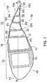
- Figure 1 shows a cross-sectional view of a wind turbine blade 10 having a skin 11.
- the blade section may comprise a deformable trailing edge portion 12 and a substantially non-deformable portion 13.
- Figure 1 shows two states of the blade section: an initial shape indicated by dotted lines 12a where the trailing edge is non-deformed and a deformed shape indicated by solid lines where the trailing edge portion 12 is deformed.
- the deformable trailing edge may extend on the total length of the blade or it may extend on at least one section of the blade, e.g. on substantially one third of the total length, in particular the portion closest to the tip of the blade. In other cases, a plurality of deformable trailing edge sections may also be provided.
- a spar box 14 may be arranged inside the substantially non-deformable portion 13 of the blade in order to maintain the distance between an inner surface of a suction side 15 of the blade and an inner surface of a pressure side 16 of the blade.
- the spar box 14 may support wind loads acting on the blades, and in particular the blade bending loads.
- a rigid structure 17 may further be arranged inside the substantially non-deformable portion 13 of the blade. Such a structure 17 may support at least in part the loads derived from the deformable trailing edge 12 and may have a substantially C-shaped cross-section, the upper and lower parts of the C supporting the blade skin.
- the embodiment shown in figure 1 may comprise five piezoelectric actuators P1-P5 arranged inside the trailing edge portion 12.
- Actuators P1, P3 and P5 may be mounted below a chord line A-A of the blade cross-section thus being lower actuators and actuators P2 and P4 may be mounted above the chord line A-A of the blade thus being upper actuators.
- the lower actuators may be mounted substantially tangential to an inner surface of a pressure side 16 of the blade skin and the upper actuators may be mounted substantially tangential to an inner surface of a suction side 15 of the blade skin.
- Rigid links 20-23 may further be provided for connecting each actuator to the next consecutive actuator.
- the rigid links may be structural elements, e.g. beams, having a sufficient stiffness such as not to deform, in particular under the influence of the actuators.
- rigid link 20 may connect a downstream end (arrow D) of actuator P1 with an upstream end (arrow U) of actuator P2
- rigid link 21 may connect a downstream end of actuator P2 with an upstream end of actuator P3
- rigid link 22 may connect a downstream end of actuator P3 with an upstream end of actuator P4
- rigid link 23 may connect a downstream end of actuator P4 with an upstream end of actuator P5.
- an upstream end of actuator P1 may be connected to the rigid structure 17 provided in the non-deformable portion 13 and a downstream end of actuator P5 may be connected to the blade skin at the trailing edge end 18 by a relatively rigid structure 24.
- skin areas 19 of the trailing edge portion 12 that are not supporting the actuators P1-P5, the rigid links 20-23 or the rigid structure 24 may be made of a relatively flexible material. This ensures deformability and smoothness of the blade surface upon actuation of any actuator. Elastic or elastomeric materials are example of materials conferring the needed flexibility so that cracks due to fatigue loads are reduced.
- the rest 191 of the blade skin may be made out of any known composite material typically used in wind turbine blades construction in order to maintain blade's high rigidity and resistance to fatigue and wear while not compromising its weight.
- the skin areas supporting the rigid links may be made from the same relatively flexible material (see figure 2d ), since the rigid links may give sufficient support by themselves.
- a control system for controlling the actuators may also be provided.
- the control system may apply an electrical field on the piezoelectric elements so as to generate a mechanical strain (deformation) on the surface (blade skin) on which the actuators are being mounted.
- each actuator converts the input signal received from the control system into an internal mechanical deformation of the piezoelectric element thus deforming the surface of the blade on which it is mounted.
- the rigid links ensure a combined effect between the actuators. Loads acting on the blade may thus be easily compensated by adapting the shape of the blade.
- each of the piezoelectric elements may be deformed in an upwards manner, a downwards manner or may be maintained in the default neutral position.
- a very large number of combinations of flap angle and/or chord length of the blade may be available to adjust lift (and drag and pitch moment) to adapt to changing wind loads.
- chord line is the imaginary straight line defined between the leading and trailing edge when the flap angle is zero.
- actuating the trailing edge portion towards its positive position increases the lift.
- the loads on a blade may thus be increased, but this may be acceptable and/or desirable, in accordance with circumstances (e.g. sudden temporary decrease in wind speed).
- the increase of the lift increases the aerodynamic torque of the rotor.
- actuating a trailing edge portion towards its negative position decreases the lift.
- the decrease in lift reduces the aerodynamic torque and the loads on the blade in general. Deforming the trailing edge towards suction side may thus be used to counteract e.g. temporary high loads on a blade (sudden wind gusts).
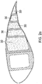
- FIGS 2a-2d show alternative embodiments. The same reference numbers will be used for matching parts.
- inner areas 30 of the blade trailing edge portion 12 may be filled with a material with a honeycomb structure.
- This kind of material may be relatively lightweight and display a desirable anisotropic behavior: it may be relatively stiff in a direction substantially perpendicular to the chord line, i.e. it is stiff so as to maintain the airfoil thickness and not deform under aerodynamic pressure. At the same time, it may be more flexible in a direction substantially parallel to the chord line, thus allowing proper movement of the actuators.
- a honeycomb structure material instead of a honeycomb structure material, other kinds of lightweight materials having such anisotropic properties so as to permit an internal structural behavior may also be used.
- FIG 2b differs from that of figure 2a in that the rigid links 20-23 may be mounted substantially perpendicular to the blade skin at their end 20u, 21 u, 22u and 23u connecting upstream ends U of actuators P2-P5.
- the rigid links 20-23 may be mounted substantially perpendicular to the blade skin at their end 20u, 21 u, 22u and 23u connecting upstream ends U of actuators P2-P5.
- FIG 2c differs from that of figure 1 in that those inner areas 31 of the blade trailing edge portion 12 which are immediately next to the flexible material used for skin areas 19 of the trailing edge portion may comprise a honeycomb structure material (or similar) lying over the flexible material.
- the skin surface may thus be particularly stiff to withstand aerodynamic loads, but more easily allow deformation of the skin in a direction perpendicular to that. If e.g. the most upstream lower actuator is activated, the rigid link between this actuator and the consecutive upper actuator will move axially.
- An anisotropic material such as the one described may be particularly suitable.
- actuators P2-P4 although being respectively upper or lower actuators as explained in connection with figure 1 , are not mounted tangential to the blade skin but they may be horizontally mounted in between two rigid links, i.e. P2 may be mounted in between rigid links 20 and 21, P3 in between rigid links 21 and 22 and P4 in between rigid links 22 and 23a.
- a suction side 15 of the blade skin along almost the whole trailing edge 12 may be made of a substantially flexible material 19' (with the exception of the trailing edge end 18 and the area on which structural element 24 rests) and a pressure side 16 of the blade skin along almost the whole trailing edge 12 (with the exception of the areas on which actuators P1 and P5 and rigid link 20 rest) may also be made of a flexible material 19".
- the alternative illustrated in figure 2d may comprise inner areas 30 of the blade trailing edge portion 12 that may be filled with a honeycomb structure material as explained above in connection with figure 2a .
- the rigid links are not supported by "normal” skin material i.e. any known composite material typically used in wind turbine blades construction. Because of the rigidity of the links, no stiff skin material is needed and thus manufacture of the blade may be simplified. Alternatively, the rigid links may be supported by normal skin material.
- Figure 3 shows a cross-sectional view of a wind turbine blade 10' according to another embodiment.
- the same reference numbers will be used for matching parts.
- the embodiment of figure 3 may comprise two piezoelectric actuators P1' and P2' that may be arranged respectively below (lower actuator) and above (upper actuator) a chord line (not shown) of the blade section.
- a substantially rigid element in the form of a rigid beam 17' may emerge from the spar box 14 towards the trailing edge end 18.
- the lower actuator P1' may be mounted in between such a rigid beam 17' and a rigid link 20' connecting a downstream end D1 of actuator P1' with an upstream end U2 of actuator P2' and a downstream end D2 of actuator P2' may be connected to a further structural element 24' connected to the trailing edge end 18.
- inner areas 30' of the blade trailing edge portion 12 may also be filled with a honeycomb structure material.
- the blade skin of almost the whole trailing edge portion 12 may be made of a flexible material 19"' with the exception of the trailing edge end 18 and that area on which structural element 24' rests.
- the basic principle lies on having at least two actuators arranged substantially downstream from one another and connected to each other by a substantially rigid link conforming an internal structure arranged inside a trailing edge portion of a blade section such that upon activation of any of the actuators a structural shape of the trailing edge portion changes.
- actuators described are piezoelectric elements, it should be understood that other type of actuators having a substantially instantaneously lineal behavior such as bistable elements or mechanical actuators such as pneumatic or hydraulic cylinders may also be foreseen. Furthermore, other combinations and/or quantity of actuators are also possible as long as there are at least two actuators, one being an upper actuator and the other being a lower actuator. This way, whenever three or more actuators are being used a substantially zig-zag shape can be defined.
Landscapes
- Engineering & Computer Science (AREA)
- Life Sciences & Earth Sciences (AREA)
- Sustainable Development (AREA)
- Sustainable Energy (AREA)
- Chemical & Material Sciences (AREA)
- Combustion & Propulsion (AREA)
- Mechanical Engineering (AREA)
- General Engineering & Computer Science (AREA)
- Physics & Mathematics (AREA)
- Fluid Mechanics (AREA)
- Wind Motors (AREA)
Description
- The present application relates to wind turbine blades comprising at least one deformable trailing edge section and wind turbines comprising such blades. It further relates to methods of controlling loads on such wind turbine blades.
- Modern wind turbines are commonly used to supply electricity into the electrical grid. Wind turbines generally comprise a rotor with a rotor hub and a plurality of blades. The rotor is set into rotation under the influence of the wind on the blades. The rotation of the rotor shaft drives the generator rotor either directly ("directly driven") or through the use of a gearbox. The gearbox (if present), the generator and other systems are usually mounted in a nacelle on top of a wind turbine tower.
- Pitch systems are normally employed for adapting the position of the blades to varying wind conditions. In this respect, it is known to rotate the position of each blade along its longitudinal axis in such a way that lift and drag are changed to reduce torque. This way, even though the wind speed increases, the torque transmitted by the rotor to the generator remains substantially the same. Using pitch systems may be particularly suitable for adapting the wind turbine blade to a varying wind speed. However, the control of the pitch systems may be rather slow and may not be suitable to react to a sudden wind gust or any other high rate changing wind conditions.
- Some systems change the aerodynamics of a wind turbine blade by providing the blade with a trailing edge flap hinged to a main body. However, deflecting the aerodynamic surface about a hinged point may lead to flow separation which may cause abrupt aerodynamic changes thus decreasing load alleviation and reducing efficiency of the wind turbine.
- Document
WO2004/088130 describes the control of aerodynamic forces substantially instantaneously and locally along the blades of a wind turbine rotor by continuous variation of the airfoil geometry in the leading edge region and trailing edge region along part or the whole blade span. It further describes the use of smart materials or mechanical actuators integrated in a deformable material changing the outer geometry in the leading and trailing edge region and thereby changing the blade section aerodynamic forces. - It is an object of the present disclosure to provide an improved blade allowing variation of airfoil geometry.
- In a first aspect a wind turbine blade is provided. The blade comprises at least one deformable trailing edge section having a plurality of actuators consecutively arranged substantially downstream from one another and a control system for controlling the actuators, wherein a downstream end of one actuator is connected by a substantially rigid link with an upstream end of the next actuator; and the plurality of actuators comprises an upper actuator being mounted above a chord line of the blade section and a lower actuator being mounted below a chord line of the blade section.
- According to this aspect, at least one upper actuator and at least one lower actuator are provided inside the trailing edge section. This ensures at least two degrees of freedom to the control system. Furthermore, the fact that two consecutive actuators are connected to each other by a rigid link ensures a leverage effect between them. The actuators may thus reinforce each other, or at least partially cancel one another's effects. The blade's trailing edge shape may thus be widely changed upon activation of the actuators. This modifies the aerodynamic surface of the blade so that it can be used to e.g. mitigate the loads acting on the blades. All this may be achieved without excessively complicating a wind turbine blade structure.
- In some embodiments, at least one upper actuator may be mounted close to an inner surface of a suction side of a skin of the blade trailing edge section and at least one lower actuator may be mounted close to an inner surface of a pressure side of a skin of the blade trailing edge section. Mounting the actuators close to opposite inner surfaces of the blade' skin improves the shape of the deflected trailing edge and the leverage action between consecutive actuators can be increased. In some of these cases, the at least one upper actuator may be mounted directly to the inner surface of the suction side of the blade skin and the at least one lower actuator may be mounted directly to the inner surface of the pressure side of the blade skin.
- In some embodiments, the rigid links connected to the upstream end of the actuators may be mounted substantially perpendicular to the blade skin. This way, the aerodynamic profile may be changed in a very smooth manner, e.g. reducing or avoiding local bulging of a profile.
- Another aspect provides a wind turbine comprising at least one blade substantially as hereinbefore described.
- A further aspect provides a method of controlling a wind turbine blade substantially as hereinbefore described, the method comprising activating at least one upper and/or at least one lower actuator such that a structural shape of the blade trailing edge changes in at least two degrees of freedom, e.g. flap angle and chord length.
- Additional objects, advantages and features of embodiments of the present invention will become apparent to those skilled in the art upon examination of the description, or may be learned by practice of the invention.
- Particular embodiments of the present invention will be described in the following by way of non-limiting examples, with reference to the appended drawings, in which:
-
Figure 1 shows a cross-sectional view of a wind turbine blade according to an embodiment; -
Figures 2a-2d show cross-sectional views of wind turbine blades according to other embodiments; and -
Figure 3 shows a cross-sectional view of a wind turbine blade according to yet another embodiment. -
Figure 1 shows a cross-sectional view of awind turbine blade 10 having askin 11. The blade section may comprise a deformabletrailing edge portion 12 and a substantiallynon-deformable portion 13.Figure 1 shows two states of the blade section: an initial shape indicated bydotted lines 12a where the trailing edge is non-deformed and a deformed shape indicated by solid lines where the trailingedge portion 12 is deformed. - The deformable trailing edge may extend on the total length of the blade or it may extend on at least one section of the blade, e.g. on substantially one third of the total length, in particular the portion closest to the tip of the blade. In other cases, a plurality of deformable trailing edge sections may also be provided.
- A
spar box 14 may be arranged inside the substantiallynon-deformable portion 13 of the blade in order to maintain the distance between an inner surface of asuction side 15 of the blade and an inner surface of a pressure side 16 of the blade. Thespar box 14 may support wind loads acting on the blades, and in particular the blade bending loads. Arigid structure 17 may further be arranged inside the substantiallynon-deformable portion 13 of the blade. Such astructure 17 may support at least in part the loads derived from thedeformable trailing edge 12 and may have a substantially C-shaped cross-section, the upper and lower parts of the C supporting the blade skin. - The embodiment shown in
figure 1 may comprise five piezoelectric actuators P1-P5 arranged inside the trailingedge portion 12. Actuators P1, P3 and P5 may be mounted below a chord line A-A of the blade cross-section thus being lower actuators and actuators P2 and P4 may be mounted above the chord line A-A of the blade thus being upper actuators. According to this embodiment, the lower actuators may be mounted substantially tangential to an inner surface of a pressure side 16 of the blade skin and the upper actuators may be mounted substantially tangential to an inner surface of asuction side 15 of the blade skin. - Rigid links 20-23 may further be provided for connecting each actuator to the next consecutive actuator. It should be understood that the rigid links may be structural elements, e.g. beams, having a sufficient stiffness such as not to deform, in particular under the influence of the actuators.
- In
figure 1 ,rigid link 20 may connect a downstream end (arrow D) of actuator P1 with an upstream end (arrow U) of actuator P2,rigid link 21 may connect a downstream end of actuator P2 with an upstream end of actuator P3,rigid link 22 may connect a downstream end of actuator P3 with an upstream end of actuator P4 andrigid link 23 may connect a downstream end of actuator P4 with an upstream end of actuator P5. Furthermore, an upstream end of actuator P1 may be connected to therigid structure 17 provided in thenon-deformable portion 13 and a downstream end of actuator P5 may be connected to the blade skin at the trailingedge end 18 by a relativelyrigid structure 24. - In addition,
skin areas 19 of the trailingedge portion 12 that are not supporting the actuators P1-P5, the rigid links 20-23 or therigid structure 24 may be made of a relatively flexible material. This ensures deformability and smoothness of the blade surface upon actuation of any actuator. Elastic or elastomeric materials are example of materials conferring the needed flexibility so that cracks due to fatigue loads are reduced. Therest 191 of the blade skin may be made out of any known composite material typically used in wind turbine blades construction in order to maintain blade's high rigidity and resistance to fatigue and wear while not compromising its weight. - In an alternative example, the skin areas supporting the rigid links may be made from the same relatively flexible material (see
figure 2d ), since the rigid links may give sufficient support by themselves. - A control system for controlling the actuators may also be provided. In the example illustrated in
figure 1 the control system may apply an electrical field on the piezoelectric elements so as to generate a mechanical strain (deformation) on the surface (blade skin) on which the actuators are being mounted. Based on the reverse piezoelectric effect, each actuator converts the input signal received from the control system into an internal mechanical deformation of the piezoelectric element thus deforming the surface of the blade on which it is mounted. The rigid links ensure a combined effect between the actuators. Loads acting on the blade may thus be easily compensated by adapting the shape of the blade. - In the example of
figure 1 , many combinations of piezoelectric activation may be possible: each of the piezoelectric elements may be deformed in an upwards manner, a downwards manner or may be maintained in the default neutral position. Using the plurality of actuators, a very large number of combinations of flap angle and/or chord length of the blade may be available to adjust lift (and drag and pitch moment) to adapt to changing wind loads. - As used herein the chord line is the imaginary straight line defined between the leading and trailing edge when the flap angle is zero. Considering a sign convention in which a minus sign is used for deformation of the trailing edge towards the suction side and a plus sign is used for a deformation of the trailing edge towards the pressure side, the following cases are only some of several possible combinations available for the embodiment of
figure 1 : - Case 1: actuators P1, P3 and P5 may be deformed towards the pressure side and actuators P2 and P4 may be deformed towards the suction side, then the flap angle may be substantially maintained but the chord length may be extended. The lift coefficient may thus be slightly modified with a larger chord length. This may provide higher lift.
- Case 2: actuators P1, P3 and P5 may be deformed towards the suction side and actuators P2 and P4 may be deformed towards the pressure side, then the flap angle may be substantially maintained and the chord length may be reduced. The lift coefficient may thus be slightly modified with a shorter chord length. This may provide lower lift.
- Case 3: actuators P1, P3, P4 and P5 may be deformed towards the suction side and actuator P2 may be deformed towards the pressure side, the flap angle may thus be reduced while the chord length may be only slightly modified. The lift may be lowered.
- Case 4: actuators P1, P3, P4 and P5 may be deformed towards the pressure side and actuator P2 may be deformed towards the suction side, the flap angle may thus be increased while the chord length may be only slightly modified. The lift may be increased.
- Case 5: only actuator P1 may be deformed. In this case, the deformable trailing edge may act substantially as a hinged flap.
- Case 6: all actuators may be deformed towards the pressure side. In this case, the chord length may remain substantially the same and the lift may be increased.
- Clearly, many other options are available.
- In general for blades having a positive angle of attack, actuating the trailing edge portion towards its positive position (pressure side) increases the lift. The loads on a blade may thus be increased, but this may be acceptable and/or desirable, in accordance with circumstances (e.g. sudden temporary decrease in wind speed). The increase of the lift increases the aerodynamic torque of the rotor. Furthermore, actuating a trailing edge portion towards its negative position (suction side) decreases the lift. The decrease in lift reduces the aerodynamic torque and the loads on the blade in general. Deforming the trailing edge towards suction side may thus be used to counteract e.g. temporary high loads on a blade (sudden wind gusts).
-
Figures 2a-2d show alternative embodiments. The same reference numbers will be used for matching parts. - The alternative illustrated in
figure 2a differs from that offigure 1 in thatinner areas 30 of the blade trailingedge portion 12 may be filled with a material with a honeycomb structure. This kind of material may be relatively lightweight and display a desirable anisotropic behavior: it may be relatively stiff in a direction substantially perpendicular to the chord line, i.e. it is stiff so as to maintain the airfoil thickness and not deform under aerodynamic pressure. At the same time, it may be more flexible in a direction substantially parallel to the chord line, thus allowing proper movement of the actuators. In other implementations, instead of a honeycomb structure material, other kinds of lightweight materials having such anisotropic properties so as to permit an internal structural behavior may also be used. - The alternative illustrated in
figure 2b differs from that offigure 2a in that the rigid links 20-23 may be mounted substantially perpendicular to the blade skin at theirend - The alternative illustrated in
figure 2c differs from that offigure 1 in that thoseinner areas 31 of the blade trailingedge portion 12 which are immediately next to the flexible material used forskin areas 19 of the trailing edge portion may comprise a honeycomb structure material (or similar) lying over the flexible material. The skin surface may thus be particularly stiff to withstand aerodynamic loads, but more easily allow deformation of the skin in a direction perpendicular to that. If e.g. the most upstream lower actuator is activated, the rigid link between this actuator and the consecutive upper actuator will move axially. An anisotropic material such as the one described may be particularly suitable. - The alternative illustrated in
figure 2d differs from that offigure 2a in that actuators P2-P4 although being respectively upper or lower actuators as explained in connection withfigure 1 , are not mounted tangential to the blade skin but they may be horizontally mounted in between two rigid links, i.e. P2 may be mounted in betweenrigid links rigid links rigid links 22 and 23a. With this internal structure, asuction side 15 of the blade skin along almost the whole trailingedge 12 may be made of a substantially flexible material 19' (with the exception of the trailingedge end 18 and the area on whichstructural element 24 rests) and a pressure side 16 of the blade skin along almost the whole trailing edge 12 (with the exception of the areas on which actuators P1 and P5 andrigid link 20 rest) may also be made of aflexible material 19". Furthermore, the alternative illustrated infigure 2d may compriseinner areas 30 of the blade trailingedge portion 12 that may be filled with a honeycomb structure material as explained above in connection withfigure 2a . - Contrary to previous examples, the rigid links are not supported by "normal" skin material i.e. any known composite material typically used in wind turbine blades construction. Because of the rigidity of the links, no stiff skin material is needed and thus manufacture of the blade may be simplified. Alternatively, the rigid links may be supported by normal skin material.
-
Figure 3 shows a cross-sectional view of a wind turbine blade 10' according to another embodiment. The same reference numbers will be used for matching parts. - The embodiment of
figure 3 may comprise two piezoelectric actuators P1' and P2' that may be arranged respectively below (lower actuator) and above (upper actuator) a chord line (not shown) of the blade section. In this case a substantially rigid element in the form of a rigid beam 17' may emerge from thespar box 14 towards the trailingedge end 18. In order to arrange both actuators P1' and P2' substantially downstream from one another, the lower actuator P1' may be mounted in between such a rigid beam 17' and a rigid link 20' connecting a downstream end D1 of actuator P1' with an upstream end U2 of actuator P2' and a downstream end D2 of actuator P2' may be connected to a further structural element 24' connected to the trailingedge end 18. In this case inner areas 30' of the blade trailingedge portion 12 may also be filled with a honeycomb structure material. Furthermore, the blade skin of almost the wholetrailing edge portion 12 may be made of aflexible material 19"' with the exception of the trailingedge end 18 and that area on which structural element 24' rests. - As explained above, the basic principle lies on having at least two actuators arranged substantially downstream from one another and connected to each other by a substantially rigid link conforming an internal structure arranged inside a trailing edge portion of a blade section such that upon activation of any of the actuators a structural shape of the trailing edge portion changes.
- Although the actuators described are piezoelectric elements, it should be understood that other type of actuators having a substantially instantaneously lineal behavior such as bistable elements or mechanical actuators such as pneumatic or hydraulic cylinders may also be foreseen. Furthermore, other combinations and/or quantity of actuators are also possible as long as there are at least two actuators, one being an upper actuator and the other being a lower actuator. This way, whenever three or more actuators are being used a substantially zig-zag shape can be defined.
- Although only a number of particular embodiments and examples of the invention have been disclosed herein, it will be understood by those skilled in the art that other alternative embodiments and/or uses of the invention and obvious modifications and equivalents thereof are possible. Furthermore, the present invention covers all possible combinations of the particular embodiments described. Thus, the scope of the present invention should not be limited by particular embodiments, but should be determined only by a fair reading of the claims that follow.
Claims (16)
- Wind turbine blade (10; 10') comprising at least one deformable trailing edge section (12) having
a plurality of actuators (P1, P2, P3, P4, P5; P1', P2') and a control system for controlling the actuators, the plurality of actuators (P1, P2, P3, P4, P5; P1', P2') comprises an upper actuator (P2, P4; P2') being mounted above a chord line (A-A) of the blade section and a lower actuator (P1, P3, P5; P1') being mounted below a chord line (A-A) of the blade section,
characterized in that the plurality of actuators (P1, P2, P3, P4, P5; P1', P2') is consecutively arranged substantially downstream from one another and in that a downstream end (D; D1, D2) of one actuator is connected by a substantially rigid link (20, 21, 22, 23; 20') with an upstream end (U; U2) of the next actuator. - Wind turbine blade according to claim 1, wherein the actuators (P1, P2, P3, P4, P5; P1', P2') are alternatingly upper and lower actuators.
- Wind turbine blade according to any of claims 1 or 2, wherein the actuators (P1, P2, P3, P4, P5; P1', P2') are linked such that upon activation of at least one upper (P2, P4; P2') and/or at least one lower (P1, P3, P5; P1') actuator a structural shape of the blade trailing edge section (12) changes in at least two degrees of freedom.
- Wind turbine blade according to claim 3, wherein the actuators (P1, P2, P3, P4, P5; P1', P2') are linked such that upon activation of at least one upper (P2, P4; P2') and/or at least one lower (P1, P3, P5; P1') actuator at least one of a flap angle and a chord length of the blade is changed.
- Wind turbine blade according to any of claims 1-4, wherein at least one upper actuator (P2, P4) is mounted close to an inner surface of a suction side (15) of a skin of the blade trailing edge section and at least one lower actuator (P1, P3, P5) is mounted close to an inner surface of a pressure side (16) of a skin of the blade trailing edge section.
- Wind turbine blade according to claim 5, wherein the actuators (P1, P2, P3, P4, P5; P1', P2') are mounted substantially parallel to the blade skin.
- Wind turbine blade according to any of claims 1-6, wherein the rigid links (20, 21, 22, 23) connected to the upstream end (U) of the actuators are mounted substantially perpendicular to the blade skin.
- Wind turbine blade according to any of claims 1-7, wherein the actuators (P1, P2, P3, P4, P5; P1', P2') are selected among a group consisting of piezoelectric elements, bistable elements and pneumatic or hydraulic actuators.
- Wind turbine blade according to any of claims 1-8, wherein the deformable trailing edge section (12) extends on one third of the total length of the blade, towards a tip (18) of the blade.
- Wind turbine blade according to any of claims 1-9, wherein the deformable trailing edge section (12) spans on a range between 30% and 40% of the chord line (A-A) of the blade section.
- Wind turbine blade according to any of claims 1-10, wherein at least portions of a skin (19; 19', 19") of the blade trailing edge section, not supporting the actuators, nor the rigid links, are made of a relatively flexible material.
- Wind turbine blade according to claim 11, wherein substantially the whole blade trailing edge section skin is made of a relatively flexible material.
- Wind turbine blade according to any of claims 11-12, wherein at least inner areas (30; 31) of the blade trailing edge section (12) next to the flexible material are filled with an anisotropic material.
- Wind turbine blade according to claim 13, wherein the anisotropic material is a honeycomb structure.
- Wind turbine comprising at least one blade (10; 10') according to any of claims 1-14.
- Method of controlling loads on a wind turbine blade according to any of claims 1-14, wherein the method comprises activating at least one upper (P2, P4; P2') and/or at least one lower actuator (P1, P3, P5; P1') such that a structural shape of the blade trailing edge section (12) changes in at least two degrees of freedom.
Priority Applications (4)
| Application Number | Priority Date | Filing Date | Title |
|---|---|---|---|
| DK13382022.5T DK2757254T3 (en) | 2013-01-21 | 2013-01-21 | Wind turbine blade |
| EP13382022.5A EP2757254B1 (en) | 2013-01-21 | 2013-01-21 | Wind turbine blade |
| PCT/EP2014/051061 WO2014111585A1 (en) | 2013-01-21 | 2014-01-20 | Wind turbine blade |
| US14/762,031 US9759191B2 (en) | 2013-01-21 | 2014-01-20 | Wind turbine blade |
Applications Claiming Priority (1)
| Application Number | Priority Date | Filing Date | Title |
|---|---|---|---|
| EP13382022.5A EP2757254B1 (en) | 2013-01-21 | 2013-01-21 | Wind turbine blade |
Publications (2)
| Publication Number | Publication Date |
|---|---|
| EP2757254A1 EP2757254A1 (en) | 2014-07-23 |
| EP2757254B1 true EP2757254B1 (en) | 2016-06-01 |
Family
ID=47631396
Family Applications (1)
| Application Number | Title | Priority Date | Filing Date |
|---|---|---|---|
| EP13382022.5A Active EP2757254B1 (en) | 2013-01-21 | 2013-01-21 | Wind turbine blade |
Country Status (4)
| Country | Link |
|---|---|
| US (1) | US9759191B2 (en) |
| EP (1) | EP2757254B1 (en) |
| DK (1) | DK2757254T3 (en) |
| WO (1) | WO2014111585A1 (en) |
Cited By (1)
| Publication number | Priority date | Publication date | Assignee | Title |
|---|---|---|---|---|
| DE102018115476A1 (en) | 2018-06-27 | 2020-01-02 | Deutsches Zentrum für Luft- und Raumfahrt e.V. | profile body |
Families Citing this family (6)
| Publication number | Priority date | Publication date | Assignee | Title |
|---|---|---|---|---|
| WO2016145435A1 (en) * | 2015-03-12 | 2016-09-15 | Rensselaer Polytechnic Institute | Modular active structural vibration suppression for wind turbine blades |
| CA3016039C (en) * | 2016-02-29 | 2023-09-26 | Flexsys, Inc. | Edge morphing arrangement for an airfoil |
| US10442525B2 (en) * | 2016-05-07 | 2019-10-15 | Optivector Ltd | Rotor or propeller blade with dynamically variable geometry and other properties |
| GB201620543D0 (en) | 2016-12-02 | 2017-01-18 | Act Blade Ltd | Wind turbine blade |
| CN107559154B (en) * | 2017-09-27 | 2019-02-26 | 山东科技大学 | It is a kind of based on piezoelectricity feedback wind energy conversion system wave Flutter Suppression intelligence pitch-controlled system |
| WO2019210330A1 (en) | 2018-04-28 | 2019-10-31 | The Research Foundation For The State University Of New York | Flexible wind turbine blade with actively variable twist distribution |
Family Cites Families (17)
| Publication number | Priority date | Publication date | Assignee | Title |
|---|---|---|---|---|
| US5224826A (en) * | 1989-07-26 | 1993-07-06 | Massachusetts Institute Of Technology | Piezoelectric helicopter blade flap actuator |
| DE10009157B4 (en) * | 2000-02-26 | 2004-09-23 | Eads Deutschland Gmbh | Fluidic actuator for level actuating movements |
| US6375127B1 (en) * | 2000-07-07 | 2002-04-23 | Kari Appa | Active control surface modal system for aircraft buffet and gust load alleviation and flutter suppression |
| DE10055961B4 (en) * | 2000-11-11 | 2004-09-09 | Eads Deutschland Gmbh | Variable wing area with adjustable profile shape that extends in the span direction |
| ES2561389T3 (en) * | 2003-03-31 | 2016-02-25 | Technical University Of Denmark | Control of the power, loads and / or stability of a horizontal axis wind turbine by using a variable blade geometry control |
| WO2008003330A1 (en) * | 2006-07-07 | 2008-01-10 | Danmarks Tekniske Universitet (Technical University Of Denmark) | Variable trailing edge section geometry for wind turbine blade |
| US9039372B2 (en) * | 2007-04-30 | 2015-05-26 | Vestas Wind Systems A/S | Wind turbine blade |
| WO2008131800A1 (en) * | 2007-04-30 | 2008-11-06 | Vestas Wind Systems A/S | A wind turbine blade |
| US20090097976A1 (en) * | 2007-10-15 | 2009-04-16 | General Electric Company | Active damping of wind turbine blades |
| US20100259046A1 (en) * | 2007-11-06 | 2010-10-14 | Sridhar Kota | Active control surfaces for wind turbine blades |
| US8678324B2 (en) * | 2008-02-21 | 2014-03-25 | Cornerstone Research Group, Inc. | Passive adaptive structures |
| DK200900420A (en) * | 2009-03-26 | 2010-09-27 | Vestas Wind Sys As | A wind turbine blade comprising a trailing edge flap and a piezoelectric actuator |
| GB2473448A (en) * | 2009-09-09 | 2011-03-16 | Vestas Wind Sys As | Wind Turbine Rotor Blade With Undulating Flap Hinge Panel |
| GB2475694A (en) * | 2009-11-25 | 2011-06-01 | Vestas Wind Sys As | Flap control for wind turbine blades |
| US20130224024A1 (en) * | 2010-09-01 | 2013-08-29 | Vestas Wind Systems A/S | Rotor blade for wind turbine with movable control surface |
| EP2628946B1 (en) * | 2012-02-20 | 2017-09-27 | GE Renewable Technologies | Aerodynamic blade and method of controlling the lift of such a blade |
| DE102013011915A1 (en) * | 2013-07-17 | 2015-01-22 | Airbus Defence and Space GmbH | Changeable sash profile |
-
2013
- 2013-01-21 DK DK13382022.5T patent/DK2757254T3/en active
- 2013-01-21 EP EP13382022.5A patent/EP2757254B1/en active Active
-
2014
- 2014-01-20 US US14/762,031 patent/US9759191B2/en active Active
- 2014-01-20 WO PCT/EP2014/051061 patent/WO2014111585A1/en active Application Filing
Cited By (2)
| Publication number | Priority date | Publication date | Assignee | Title |
|---|---|---|---|---|
| DE102018115476A1 (en) | 2018-06-27 | 2020-01-02 | Deutsches Zentrum für Luft- und Raumfahrt e.V. | profile body |
| DE102018115476B4 (en) | 2018-06-27 | 2022-05-19 | Deutsches Zentrum für Luft- und Raumfahrt e.V. | profile body |
Also Published As
| Publication number | Publication date |
|---|---|
| EP2757254A1 (en) | 2014-07-23 |
| WO2014111585A1 (en) | 2014-07-24 |
| DK2757254T3 (en) | 2016-09-05 |
| US20150354536A1 (en) | 2015-12-10 |
| US9759191B2 (en) | 2017-09-12 |
Similar Documents
| Publication | Publication Date | Title |
|---|---|---|
| EP2757254B1 (en) | Wind turbine blade | |
| CN105980701B (en) | Device for relieving strain on a rotor blade of a wind turbine | |
| US10451037B2 (en) | Wind turbine blade | |
| EP2153059B2 (en) | A wind turbine blade | |
| EP2318702B1 (en) | Wind turbine rotor blade with extension portion having a skin located over a framework | |
| EP2526288B1 (en) | Segmented rotor blade extension portion | |
| EP2019203B2 (en) | Wind turbine blade with cambering flaps | |
| EP2899395B1 (en) | Wind turbine blades | |
| EP2085609B1 (en) | Wind turbine blade with cambering flaps controlled by surface pressure changes | |
| EP2034178A2 (en) | Wind turbine blade with deflectable flaps | |
| GB2464163A (en) | Variable leading edge wind turbine blade | |
| EP2998571B1 (en) | Lift influencing device for a rotor blade of a wind turbine | |
| EP2937558B1 (en) | Flow deflection device of a wind turbine and method | |
| WO2012103891A2 (en) | A wind turbine blade having a flap | |
| US10422318B2 (en) | Wind turbine blade | |
| EP3673171B1 (en) | A wind turbine blade and a method of operating such a wind turbine blade | |
| EP2577050B1 (en) | Method for reducing fluid flow induced forces produced by vortex shedding on a wind turbine rotor blade | |
| WO2024209197A1 (en) | Turbine blade | |
| DK201270436A (en) | Wind turbine blade having a flap |
Legal Events
| Date | Code | Title | Description |
|---|---|---|---|
| PUAI | Public reference made under article 153(3) epc to a published international application that has entered the european phase |
Free format text: ORIGINAL CODE: 0009012 |
|
| 17P | Request for examination filed |
Effective date: 20130121 |
|
| AK | Designated contracting states |
Kind code of ref document: A1 Designated state(s): AL AT BE BG CH CY CZ DE DK EE ES FI FR GB GR HR HU IE IS IT LI LT LU LV MC MK MT NL NO PL PT RO RS SE SI SK SM TR |
|
| AX | Request for extension of the european patent |
Extension state: BA ME |
|
| R17P | Request for examination filed (corrected) |
Effective date: 20150123 |
|
| RBV | Designated contracting states (corrected) |
Designated state(s): AL AT BE BG CH CY CZ DE DK EE ES FI FR GB GR HR HU IE IS IT LI LT LU LV MC MK MT NL NO PL PT RO RS SE SI SK SM TR |
|
| GRAP | Despatch of communication of intention to grant a patent |
Free format text: ORIGINAL CODE: EPIDOSNIGR1 |
|
| INTG | Intention to grant announced |
Effective date: 20151222 |
|
| GRAS | Grant fee paid |
Free format text: ORIGINAL CODE: EPIDOSNIGR3 |
|
| GRAA | (expected) grant |
Free format text: ORIGINAL CODE: 0009210 |
|
| AK | Designated contracting states |
Kind code of ref document: B1 Designated state(s): AL AT BE BG CH CY CZ DE DK EE ES FI FR GB GR HR HU IE IS IT LI LT LU LV MC MK MT NL NO PL PT RO RS SE SI SK SM TR |
|
| REG | Reference to a national code |
Ref country code: GB Ref legal event code: FG4D |
|
| REG | Reference to a national code |
Ref country code: CH Ref legal event code: EP Ref country code: AT Ref legal event code: REF Ref document number: 804039 Country of ref document: AT Kind code of ref document: T Effective date: 20160615 |
|
| REG | Reference to a national code |
Ref country code: IE Ref legal event code: FG4D |
|
| REG | Reference to a national code |
Ref country code: DE Ref legal event code: R096 Ref document number: 602013008186 Country of ref document: DE |
|
| REG | Reference to a national code |
Ref country code: DK Ref legal event code: T3 Effective date: 20160901 |
|
| REG | Reference to a national code |
Ref country code: LT Ref legal event code: MG4D |
|
| REG | Reference to a national code |
Ref country code: NL Ref legal event code: MP Effective date: 20160601 |
|
| RAP2 | Party data changed (patent owner data changed or rights of a patent transferred) |
Owner name: ALSTOM RENEWABLE TECHNOLOGIES |
|
| PG25 | Lapsed in a contracting state [announced via postgrant information from national office to epo] |
Ref country code: LT Free format text: LAPSE BECAUSE OF FAILURE TO SUBMIT A TRANSLATION OF THE DESCRIPTION OR TO PAY THE FEE WITHIN THE PRESCRIBED TIME-LIMIT Effective date: 20160601 Ref country code: FI Free format text: LAPSE BECAUSE OF FAILURE TO SUBMIT A TRANSLATION OF THE DESCRIPTION OR TO PAY THE FEE WITHIN THE PRESCRIBED TIME-LIMIT Effective date: 20160601 Ref country code: NO Free format text: LAPSE BECAUSE OF FAILURE TO SUBMIT A TRANSLATION OF THE DESCRIPTION OR TO PAY THE FEE WITHIN THE PRESCRIBED TIME-LIMIT Effective date: 20160901 |
|
| REG | Reference to a national code |
Ref country code: AT Ref legal event code: MK05 Ref document number: 804039 Country of ref document: AT Kind code of ref document: T Effective date: 20160601 |
|
| PG25 | Lapsed in a contracting state [announced via postgrant information from national office to epo] |
Ref country code: RS Free format text: LAPSE BECAUSE OF FAILURE TO SUBMIT A TRANSLATION OF THE DESCRIPTION OR TO PAY THE FEE WITHIN THE PRESCRIBED TIME-LIMIT Effective date: 20160601 Ref country code: LV Free format text: LAPSE BECAUSE OF FAILURE TO SUBMIT A TRANSLATION OF THE DESCRIPTION OR TO PAY THE FEE WITHIN THE PRESCRIBED TIME-LIMIT Effective date: 20160601 Ref country code: SE Free format text: LAPSE BECAUSE OF FAILURE TO SUBMIT A TRANSLATION OF THE DESCRIPTION OR TO PAY THE FEE WITHIN THE PRESCRIBED TIME-LIMIT Effective date: 20160601 Ref country code: NL Free format text: LAPSE BECAUSE OF FAILURE TO SUBMIT A TRANSLATION OF THE DESCRIPTION OR TO PAY THE FEE WITHIN THE PRESCRIBED TIME-LIMIT Effective date: 20160601 Ref country code: ES Free format text: LAPSE BECAUSE OF FAILURE TO SUBMIT A TRANSLATION OF THE DESCRIPTION OR TO PAY THE FEE WITHIN THE PRESCRIBED TIME-LIMIT Effective date: 20160601 Ref country code: HR Free format text: LAPSE BECAUSE OF FAILURE TO SUBMIT A TRANSLATION OF THE DESCRIPTION OR TO PAY THE FEE WITHIN THE PRESCRIBED TIME-LIMIT Effective date: 20160601 Ref country code: GR Free format text: LAPSE BECAUSE OF FAILURE TO SUBMIT A TRANSLATION OF THE DESCRIPTION OR TO PAY THE FEE WITHIN THE PRESCRIBED TIME-LIMIT Effective date: 20160902 |
|
| PG25 | Lapsed in a contracting state [announced via postgrant information from national office to epo] |
Ref country code: IT Free format text: LAPSE BECAUSE OF FAILURE TO SUBMIT A TRANSLATION OF THE DESCRIPTION OR TO PAY THE FEE WITHIN THE PRESCRIBED TIME-LIMIT Effective date: 20160601 Ref country code: SK Free format text: LAPSE BECAUSE OF FAILURE TO SUBMIT A TRANSLATION OF THE DESCRIPTION OR TO PAY THE FEE WITHIN THE PRESCRIBED TIME-LIMIT Effective date: 20160601 Ref country code: RO Free format text: LAPSE BECAUSE OF FAILURE TO SUBMIT A TRANSLATION OF THE DESCRIPTION OR TO PAY THE FEE WITHIN THE PRESCRIBED TIME-LIMIT Effective date: 20160601 Ref country code: IS Free format text: LAPSE BECAUSE OF FAILURE TO SUBMIT A TRANSLATION OF THE DESCRIPTION OR TO PAY THE FEE WITHIN THE PRESCRIBED TIME-LIMIT Effective date: 20161001 Ref country code: EE Free format text: LAPSE BECAUSE OF FAILURE TO SUBMIT A TRANSLATION OF THE DESCRIPTION OR TO PAY THE FEE WITHIN THE PRESCRIBED TIME-LIMIT Effective date: 20160601 Ref country code: CZ Free format text: LAPSE BECAUSE OF FAILURE TO SUBMIT A TRANSLATION OF THE DESCRIPTION OR TO PAY THE FEE WITHIN THE PRESCRIBED TIME-LIMIT Effective date: 20160601 |
|
| PG25 | Lapsed in a contracting state [announced via postgrant information from national office to epo] |
Ref country code: PT Free format text: LAPSE BECAUSE OF FAILURE TO SUBMIT A TRANSLATION OF THE DESCRIPTION OR TO PAY THE FEE WITHIN THE PRESCRIBED TIME-LIMIT Effective date: 20161003 Ref country code: AT Free format text: LAPSE BECAUSE OF FAILURE TO SUBMIT A TRANSLATION OF THE DESCRIPTION OR TO PAY THE FEE WITHIN THE PRESCRIBED TIME-LIMIT Effective date: 20160601 Ref country code: PL Free format text: LAPSE BECAUSE OF FAILURE TO SUBMIT A TRANSLATION OF THE DESCRIPTION OR TO PAY THE FEE WITHIN THE PRESCRIBED TIME-LIMIT Effective date: 20160601 Ref country code: SM Free format text: LAPSE BECAUSE OF FAILURE TO SUBMIT A TRANSLATION OF THE DESCRIPTION OR TO PAY THE FEE WITHIN THE PRESCRIBED TIME-LIMIT Effective date: 20160601 Ref country code: BE Free format text: LAPSE BECAUSE OF FAILURE TO SUBMIT A TRANSLATION OF THE DESCRIPTION OR TO PAY THE FEE WITHIN THE PRESCRIBED TIME-LIMIT Effective date: 20160601 |
|
| REG | Reference to a national code |
Ref country code: DE Ref legal event code: R097 Ref document number: 602013008186 Country of ref document: DE |
|
| PLBE | No opposition filed within time limit |
Free format text: ORIGINAL CODE: 0009261 |
|
| STAA | Information on the status of an ep patent application or granted ep patent |
Free format text: STATUS: NO OPPOSITION FILED WITHIN TIME LIMIT |
|
| 26N | No opposition filed |
Effective date: 20170302 |
|
| PG25 | Lapsed in a contracting state [announced via postgrant information from national office to epo] |
Ref country code: SI Free format text: LAPSE BECAUSE OF FAILURE TO SUBMIT A TRANSLATION OF THE DESCRIPTION OR TO PAY THE FEE WITHIN THE PRESCRIBED TIME-LIMIT Effective date: 20160601 |
|
| REG | Reference to a national code |
Ref country code: CH Ref legal event code: PL |
|
| GBPC | Gb: european patent ceased through non-payment of renewal fee |
Effective date: 20170121 |
|
| PG25 | Lapsed in a contracting state [announced via postgrant information from national office to epo] |
Ref country code: MC Free format text: LAPSE BECAUSE OF FAILURE TO SUBMIT A TRANSLATION OF THE DESCRIPTION OR TO PAY THE FEE WITHIN THE PRESCRIBED TIME-LIMIT Effective date: 20160601 |
|
| REG | Reference to a national code |
Ref country code: FR Ref legal event code: ST Effective date: 20170929 |
|
| PG25 | Lapsed in a contracting state [announced via postgrant information from national office to epo] |
Ref country code: FR Free format text: LAPSE BECAUSE OF NON-PAYMENT OF DUE FEES Effective date: 20170131 Ref country code: LI Free format text: LAPSE BECAUSE OF NON-PAYMENT OF DUE FEES Effective date: 20170131 Ref country code: CH Free format text: LAPSE BECAUSE OF NON-PAYMENT OF DUE FEES Effective date: 20170131 |
|
| REG | Reference to a national code |
Ref country code: IE Ref legal event code: MM4A |
|
| REG | Reference to a national code |
Ref country code: DE Ref legal event code: R081 Ref document number: 602013008186 Country of ref document: DE Owner name: ALSTOM RENEWABLE TECHNOLOGIES, FR Free format text: FORMER OWNER: ALSTOM WIND, S.L.U., BARCELONA, ES |
|
| PG25 | Lapsed in a contracting state [announced via postgrant information from national office to epo] |
Ref country code: LU Free format text: LAPSE BECAUSE OF NON-PAYMENT OF DUE FEES Effective date: 20170121 Ref country code: GB Free format text: LAPSE BECAUSE OF NON-PAYMENT OF DUE FEES Effective date: 20170121 |
|
| PG25 | Lapsed in a contracting state [announced via postgrant information from national office to epo] |
Ref country code: IE Free format text: LAPSE BECAUSE OF NON-PAYMENT OF DUE FEES Effective date: 20170121 |
|
| PG25 | Lapsed in a contracting state [announced via postgrant information from national office to epo] |
Ref country code: MT Free format text: LAPSE BECAUSE OF NON-PAYMENT OF DUE FEES Effective date: 20170121 |
|
| PG25 | Lapsed in a contracting state [announced via postgrant information from national office to epo] |
Ref country code: AL Free format text: LAPSE BECAUSE OF FAILURE TO SUBMIT A TRANSLATION OF THE DESCRIPTION OR TO PAY THE FEE WITHIN THE PRESCRIBED TIME-LIMIT Effective date: 20160601 |
|
| PG25 | Lapsed in a contracting state [announced via postgrant information from national office to epo] |
Ref country code: HU Free format text: LAPSE BECAUSE OF FAILURE TO SUBMIT A TRANSLATION OF THE DESCRIPTION OR TO PAY THE FEE WITHIN THE PRESCRIBED TIME-LIMIT; INVALID AB INITIO Effective date: 20130121 |
|
| PG25 | Lapsed in a contracting state [announced via postgrant information from national office to epo] |
Ref country code: BG Free format text: LAPSE BECAUSE OF FAILURE TO SUBMIT A TRANSLATION OF THE DESCRIPTION OR TO PAY THE FEE WITHIN THE PRESCRIBED TIME-LIMIT Effective date: 20160601 |
|
| PG25 | Lapsed in a contracting state [announced via postgrant information from national office to epo] |
Ref country code: CY Free format text: LAPSE BECAUSE OF NON-PAYMENT OF DUE FEES Effective date: 20160601 |
|
| PG25 | Lapsed in a contracting state [announced via postgrant information from national office to epo] |
Ref country code: MK Free format text: LAPSE BECAUSE OF FAILURE TO SUBMIT A TRANSLATION OF THE DESCRIPTION OR TO PAY THE FEE WITHIN THE PRESCRIBED TIME-LIMIT Effective date: 20160601 |
|
| PG25 | Lapsed in a contracting state [announced via postgrant information from national office to epo] |
Ref country code: TR Free format text: LAPSE BECAUSE OF FAILURE TO SUBMIT A TRANSLATION OF THE DESCRIPTION OR TO PAY THE FEE WITHIN THE PRESCRIBED TIME-LIMIT Effective date: 20160601 |
|
| P01 | Opt-out of the competence of the unified patent court (upc) registered |
Effective date: 20230522 |
|
| PGFP | Annual fee paid to national office [announced via postgrant information from national office to epo] |
Ref country code: DK Payment date: 20231219 Year of fee payment: 12 |
|
| PGFP | Annual fee paid to national office [announced via postgrant information from national office to epo] |
Ref country code: DE Payment date: 20231219 Year of fee payment: 12 |