EP2757062A1 - Fiber bundle supply device - Google Patents
Fiber bundle supply device Download PDFInfo
- Publication number
- EP2757062A1 EP2757062A1 EP12832445.6A EP12832445A EP2757062A1 EP 2757062 A1 EP2757062 A1 EP 2757062A1 EP 12832445 A EP12832445 A EP 12832445A EP 2757062 A1 EP2757062 A1 EP 2757062A1
- Authority
- EP
- European Patent Office
- Prior art keywords
- fiber bundle
- bobbin
- unwound
- turntable
- wound around
- Prior art date
- Legal status (The legal status is an assumption and is not a legal conclusion. Google has not performed a legal analysis and makes no representation as to the accuracy of the status listed.)
- Granted
Links
Images





Classifications
-
- B—PERFORMING OPERATIONS; TRANSPORTING
- B65—CONVEYING; PACKING; STORING; HANDLING THIN OR FILAMENTARY MATERIAL
- B65H—HANDLING THIN OR FILAMENTARY MATERIAL, e.g. SHEETS, WEBS, CABLES
- B65H49/00—Unwinding or paying-out filamentary material; Supporting, storing or transporting packages from which filamentary material is to be withdrawn or paid-out
- B65H49/18—Methods or apparatus in which packages rotate
- B65H49/20—Package-supporting devices
- B65H49/32—Stands or frameworks
-
- B—PERFORMING OPERATIONS; TRANSPORTING
- B29—WORKING OF PLASTICS; WORKING OF SUBSTANCES IN A PLASTIC STATE IN GENERAL
- B29C—SHAPING OR JOINING OF PLASTICS; SHAPING OF MATERIAL IN A PLASTIC STATE, NOT OTHERWISE PROVIDED FOR; AFTER-TREATMENT OF THE SHAPED PRODUCTS, e.g. REPAIRING
- B29C31/00—Handling, e.g. feeding of the material to be shaped, storage of plastics material before moulding; Automation, i.e. automated handling lines in plastics processing plants, e.g. using manipulators or robots
- B29C31/04—Feeding of the material to be moulded, e.g. into a mould cavity
-
- B—PERFORMING OPERATIONS; TRANSPORTING
- B29—WORKING OF PLASTICS; WORKING OF SUBSTANCES IN A PLASTIC STATE IN GENERAL
- B29C—SHAPING OR JOINING OF PLASTICS; SHAPING OF MATERIAL IN A PLASTIC STATE, NOT OTHERWISE PROVIDED FOR; AFTER-TREATMENT OF THE SHAPED PRODUCTS, e.g. REPAIRING
- B29C53/00—Shaping by bending, folding, twisting, straightening or flattening; Apparatus therefor
- B29C53/80—Component parts, details or accessories; Auxiliary operations
- B29C53/8008—Component parts, details or accessories; Auxiliary operations specially adapted for winding and joining
- B29C53/8016—Storing, feeding or applying winding materials, e.g. reels, thread guides, tensioners
-
- B—PERFORMING OPERATIONS; TRANSPORTING
- B65—CONVEYING; PACKING; STORING; HANDLING THIN OR FILAMENTARY MATERIAL
- B65H—HANDLING THIN OR FILAMENTARY MATERIAL, e.g. SHEETS, WEBS, CABLES
- B65H57/00—Guides for filamentary materials; Supports therefor
- B65H57/04—Guiding surfaces within slots or grooves
-
- B—PERFORMING OPERATIONS; TRANSPORTING
- B65—CONVEYING; PACKING; STORING; HANDLING THIN OR FILAMENTARY MATERIAL
- B65H—HANDLING THIN OR FILAMENTARY MATERIAL, e.g. SHEETS, WEBS, CABLES
- B65H67/00—Replacing or removing cores, receptacles, or completed packages at paying-out, winding, or depositing stations
- B65H67/02—Arrangements for removing spent cores or receptacles and replacing by supply packages at paying-out stations
-
- B—PERFORMING OPERATIONS; TRANSPORTING
- B65—CONVEYING; PACKING; STORING; HANDLING THIN OR FILAMENTARY MATERIAL
- B65H—HANDLING THIN OR FILAMENTARY MATERIAL, e.g. SHEETS, WEBS, CABLES
- B65H67/00—Replacing or removing cores, receptacles, or completed packages at paying-out, winding, or depositing stations
- B65H67/04—Arrangements for removing completed take-up packages and or replacing by cores, formers, or empty receptacles at winding or depositing stations; Transferring material between adjacent full and empty take-up elements
- B65H67/044—Continuous winding apparatus for winding on two or more winding heads in succession
- B65H67/048—Continuous winding apparatus for winding on two or more winding heads in succession having winding heads arranged on rotary capstan head
-
- B—PERFORMING OPERATIONS; TRANSPORTING
- B29—WORKING OF PLASTICS; WORKING OF SUBSTANCES IN A PLASTIC STATE IN GENERAL
- B29C—SHAPING OR JOINING OF PLASTICS; SHAPING OF MATERIAL IN A PLASTIC STATE, NOT OTHERWISE PROVIDED FOR; AFTER-TREATMENT OF THE SHAPED PRODUCTS, e.g. REPAIRING
- B29C53/00—Shaping by bending, folding, twisting, straightening or flattening; Apparatus therefor
- B29C53/56—Winding and joining, e.g. winding spirally
- B29C53/58—Winding and joining, e.g. winding spirally helically
- B29C53/60—Winding and joining, e.g. winding spirally helically using internal forming surfaces, e.g. mandrels
- B29C53/602—Winding and joining, e.g. winding spirally helically using internal forming surfaces, e.g. mandrels for tubular articles having closed or nearly closed ends, e.g. vessels, tanks, containers
-
- B—PERFORMING OPERATIONS; TRANSPORTING
- B65—CONVEYING; PACKING; STORING; HANDLING THIN OR FILAMENTARY MATERIAL
- B65H—HANDLING THIN OR FILAMENTARY MATERIAL, e.g. SHEETS, WEBS, CABLES
- B65H2701/00—Handled material; Storage means
- B65H2701/30—Handled filamentary material
- B65H2701/31—Textiles threads or artificial strands of filaments
Definitions
- the present invention relates to a technique of a fiber bundle supply device.
- a filament winding device which winds fiber bundles around the outer periphery surface of a liner.
- the filament winding device is provided with a fiber bundle supply part, and a plurality of bobbins around which the fiber bundle is wound are arranged in the fiber bundle supply part (for example, see Patent Literature 1).
- the fiber bundle is unwound from each bobbin arranged in the fiber bundle supply part, and the said fiber bundles are wound around the outer periphery surface of the liner.
- Patent Literature 1 the Japanese Patent Laid Open Gazette 2010-23481
- An object of the present invention is to provide a technique in which if a fiber bundle wound around one bobbin has been unwound and little remains, unwinding of a fiber bundle wound around the other bobbin is started, whereby the fiber bundle is continuously supplied.
- a first aspect of the present invention is a fiber bundle supply device including: plural bobbin holder shafts each of which supports a bobbin around which a fiber bundle is wound; and a turntable on which the bobbin holder shafts are arranged in a concentric pattern and which rotates around the central axis of said concentric circle.
- the bobbin holder shafts are configured from at least a first bobbin holder shaft which supports a first bobbin, and a second bobbin holder shaft which supports a second bobbin.
- a second aspect of the present invention is the fiber bundle supply device according to the first aspect which includes a first fiber bundle guide and a second fiber bundle guide which are installed on the turntable and which rotate with the turntable.
- the first fiber bundle guide guides the fiber bundle unwound from the first bobbin to be restricted in a prescribed trajectory.
- the second fiber bundle guide superposes the end portion of the fiber bundle wound around the second bobbin on the fiber bundle unwound from the first bobbin.
- a third aspect of the present invention is the fiber bundle supply device according to the first or the second aspect which includes a splicing device which splices the fiber bundle of the first bobbin and the fiber bundle of the second bobbin together.
- the splicing device splices the overlapped portion of the fiber bundle of the first bobbin and the fiber bundle of the second bobbin.
- a fourth aspect of the present invention is the fiber bundle supply device according to any one of the first to the third aspect which includes a cutter device which cuts the fiber bundle unwound from the first bobbin.
- the cutter device cuts the fiber bundle unwound from the first bobbin such that necessary and sufficient bonding strength is obtained when all of the overlapped portion of the fiber bundle is spliced.
- the present invention exerts effects described below.
- the fiber bundle wound around a first bobbin has been unwound and little remains, unwinding of the fiber bundle wound around a second bobbin is started, whereby the fiber bundle is continuously supplied.
- the fiber bundle can be continuously supplied.
- the end portion of the fiber bundle wound around the second bobbin can be overlapped with the fiber bundle unwound from the first bobbin and restricted in the prescribed trajectory.
- the fiber bundle of the first bobbin can be spliced with the fiber bundle of the second bobbin.
- the overlapped portion of the fiber bundle of the first bobbin and the fiber bundle of the second bobbin can be spliced.
- the fiber bundle of the first bobbin can be surely spliced with the fiber bundle of the second bobbin.
- necessary and sufficient bonding strength can be obtained with respect to the splicing portion of the fiber bundle of the first bobbin and the fiber bundle of the second bobbin. As such, required bonding strength can be secured for the splicing portion, and time required for splicing can be shortened.
- a fiber bundle supply device 32 according to the embodiment of the present invention is included in a fiber bundle supply part 30 which configures a filament winding device 100. Therefore, first of all, a brief explanation will be given of an overall configuration of the filament winding device 100 (Hereinafter referred to as "FW device 100").
- FIG. 1 illustrates the overall configuration of the FW device 100.
- An arrow D in the drawing indicates a transfer direction of a liner 1.
- the direction in parallel to the transfer direction of the liner 1 is regarded as the longitudinal direction of the FW device 100, and one direction of transferring the liner 1 and other direction opposite thereto are respectively defined as the front side and the rear side.
- the FW device 100 reciprocates the liner 1 in the longitudinal direction, whereby the front side and the rear side is defined depending on the transfer direction of the liner 1.
- the FW device 100 winds a fiber bundle F around the outer periphery surface of the liner 1.
- the FW device 100 mainly includes a liner transfer part 10, a helical winding part 20, and the fiber bundle supply part 30.
- the liner transfer part 10 transfers the liner 1 while rotating it.
- the liner 1 is rotated about the longitudinal direction of the FW device 100 as a center axis, and is transferred in the longitudinal direction of the FW device 100 by the liner transfer part 10.
- the liner transfer part 10 mainly includes a pedestal 11, liner support frames 12, and a rotational shaft 13.
- the pedestal 11 is placed on a pair of rails extending in the longitudinal direction of the FW device 100.
- the pedestal 11 is provided with the pair of liner support frames 12 and the rotational shaft 13.
- the liner 1 is attached to the rotational shaft 13 and is rotated one direction via a power mechanism (not shown).
- the liner 1 is rotated about the longitudinal direction of the FW device 100 as a center axis, and is transferred in the longitudinal direction of the FW device 100 by the liner transfer part 10.
- the helical winding part 20 winds the fiber bundles F around the outer periphery surface of the liner 1.
- the helical winding part 20 performs so-called helical winding in which the winding angle of the fiber bundle F is set to be a prescribed value relative to the longitudinal direction of the FW device 100.
- the helical winding part 20 mainly includes a pedestal 21 and a helical head 22.
- the pedestal 21 is provided with the helical head 22.
- the helical head 22 is provided with a plurality of guides 23 each of which guides the fiber bundle F.
- the fiber bundle F guided by each guide 23 is wound around the outer periphery surface of the liner 1 passing through while rotating.
- the helical winding part 20 performs so-called helical winding, where the winding angle of the fiber bundle F is set to be the prescribed value relative to the longitudinal direction of the FW device 100.
- the fiber bundle supply part 30 supplies the fiber bundles F to the helical winding part.
- the fiber bundle supply part 30 supplies the fiber bundle F to each guide 23 of the helical head 22 included in the helical winding part 20.
- the fiber bundle supply part 30 mainly includes a rack 31 and the fiber bundle supply devices 32.
- the rack 31 is provided with the plurality of fiber bundle supply devices 32.
- the fiber bundle supply device 32 supports bobbins B around which the fiber bundle F is wound. And the fiber bundle F wound around each bobbin B is supplied to the corresponding respective guide 23 through a guide member (not shown).
- the fiber bundle F is fed to each guide 23 of the helical head 22 included in the helical winding part 20 by the fiber bundle supply part 30.
- FIG. 2 illustrates the configuration of the fiber bundle supply device 32.
- explanation will be given by using the case of two-shaft type fiber bundle supply device which has two bobbin holder shafts 321, 322 each of which supports the bobbin B.
- the same object and effects according to the present invention can be achieved.
- the scope of the present invention also encompasses such a modification.
- the fiber bundle supply device 32 mainly includes the first bobbin holder shaft 321, the second bobbin holder shaft 322, a turntable 323, a first fiber bundle guide 324, and a second fiber bundle guide 325.
- the bobbin B supported by the first bobbin holder shaft 321 is defined as the first bobbin B1
- the bobbin B supported by the second bobbin holder shaft 322 is defined as the second bobbin B2.
- the first bobbin holder shaft 321 rotatably supports the first bobbin B1.
- the first bobbin B1 rotates, whereby the fiber bundle F is unwound.
- the fiber bundle F wound around the first bobbin B1 is unwound (see the black arrows in FIG. 3 ).
- the fiber bundle F unwound from the first bobbin B1 is supplied to the corresponding guide 23 of the helical head 22.
- the second bobbin holder shaft 322 rotatably supports the second bobbin B2.
- the second bobbin B2 rotates, whereby the fiber bundle F is unwound.
- the fiber bundle F wound around the second bobbin B2 is unwound (see the black arrows in FIG. 9 ).
- the fiber bundle F unwound from the second bobbin B2 is supplied to the corresponding guide 23 of the helical head 22.
- the defined discrimination between the first bobbin holder shaft 321 and the second bobbin holder shaft 322 is made for the purpose of illustration, and each of these shafts has the same configuration.
- the first bobbin holder shaft 321 and the second bobbin holder shaft 322 are arranged on a concentric circle on the turntable 323, and the turntable 323 rotates around the central axis C of said concentric circle.
- the turntable 323 is rotated around the central axis C by about 180°, the position of the first bobbin holder shaft 321 at the unwinding position P1 and the position of the second bobbin holder shaft 322 at a standby position P2 are switched with each other (see FIG. 5 ).
- the first fiber bundle guide 324 is installed on the turntable 323 and is rotated with the turntable 323.
- the first fiber bundle guide 324 guides the fiber bundle F unwound from the first bobbin B1 to be restricted in a prescribed trajectory (see FIG. 4 , FIG. 11 ).
- the first bobbin holder shaft 321 is at the standby position P2 and the first bobbin holder shaft 321 is exchanged with the second bobbin holder shaft 322 which is at the unwinding position P1
- the end portion of the fiber bundle F wound around the first bobbin B1 is superposed on the fiber bundle F unwound from the second bobbin B2. Specific configuration will be explained later.
- the second fiber bundle guide 325 is installed on the turntable 323 and is rotated with the turntable 323.
- the second fiber bundle guide 325 superposes the end portion of the fiber bundle F wound around the second bobbin B2 on the fiber bundle F unwound from the first bobbin B1 (see FIG. 5 , FIG. 12 ).
- the second bobbin holder shaft 322 is at the unwinding position P1 and the second bobbin holder shaft 322 is switched with the first bobbin holder shaft 321 which is at the standby position P2, the fiber bundle F unwound from the second bobbin B2 is guided to be restricted in the prescribed trajectory. Specific configuration will be explained later.
- the defined discrimination between the first fiber bundle guide 324 and the second fiber bundle guide 325 is made for the purpose of illustration, and each of these guides each has the same configuration.
- FIG. 3 to FIG. 10 illustrate an example of operation of the fiber bundle supply device 32 at the time of changing a bobbin.
- the black arrows in the drawings indicate the rotation direction of the first bobbin B1 and the second bobbin B2 and the sending-out direction of the fiber bundle F.
- the white arrows in the drawings indicate the rotation direction of the turntable 323.
- explanation will be given by assuming the case in which the first bobbin holder shaft 321 is at the unwinding position P1 and the second bobbin holder shaft 322 is at the standby position P2.
- FIG. 3 illustrates a state in which the fiber bundle F wound around the first bobbin B1 is unwound.
- the first bobbin B1 rotates, whereby the fiber bundle F is unwound. Since the fiber bundle F is momentarily unwound from the first bobbin B1, the remaining amount of the fiber bundle F wound around the first bobbin B1 gradually decreases. Therefore, the first bobbin B1 has to be changed to the second bobbin B2 before all of the fiber bundle F wound around the first bobbin B1 is unwound and the first bobbin B1 becomes empty.
- FIG. 4 illustrates a state in which the turntable 323 starts rotation.
- the first fiber bundle guide 324 pushes up the fiber bundle F unwound from the first bobbin B1.
- the first fiber bundle guide 324 guides the fiber bundle F unwound from the first bobbin B1 to be restricted in the prescribed trajectory.
- the first fiber bundle guide 324 includes a pair of guide walls 324a which gradually become narrow along the feeding direction of the fiber bundle F.
- the guide walls 324a lead the fiber bundle F to a bottom wall 324b.
- the fiber bundle F unwound from the first bobbin B1 is guided by the guide walls 324a and the bottom wall 324b and sent out from a fiber bundle passage 324c which is arranged at an end portion.
- the first fiber bundle guide 324 guides the fiber bundle F traversed (see "T" in the drawing) in the shaft direction of the first bobbin B1 to be restricted in the prescribed trajectory.
- FIG. 5 illustrates a state in which the rotation of the turntable 323 is terminated.
- the second fiber bundle guide 325 comes in contact with the fiber bundle F unwound from the first bobbin B1.
- the second fiber bundle guide 325 superposes the end portion of the fiber bundle F wound around the second bobbin B2 on the fiber bundle F unwound from the first bobbin B1.
- the second fiber bundle guide 325 includes a holder 325d which holds the tip end portion of the fiber bundle F.
- the holder 325d retains the fiber bundle F wound around the second bobbin B2 in such a state to run along a bottom wall 325b.
- the fiber bundle F wound around the second bobbin B2 is guided in such a state to run along the fiber bundle F unwound from the first bobbin B1.
- the second fiber bundle guide 325 superposes the end portion of the fiber bundle F wound around the second bobbin B2 on the fiber bundle F unwound from the first bobbin B1.
- the end portion of the fiber bundle F wound around the second bobbin B2 is overlapped with the fiber bundle F unwound from the first bobbin B1 and restricted in the prescribed trajectory by the present fiber bundle supply device 32.
- the fiber bundle F of the first bobbin B1 can be spliced with the fiber bundle F of the second bobbin B2.
- FIG. 6 illustrates a state where overlapped portions of the fiber bundle F are spliced by a splicing device 326.
- the overlapped portion of the fiber bundle F is nipped and held by the splicing device 326 and the second fiber bundle guide 325. Then the splicing device 326 applies heat to the overlapped portion of the fiber bundles F, whereby these fiber bundles F are spliced.
- the splicing device 326 includes a heater part 326a which becomes hot due to a flow of electric current.
- the heater part 326a applies heat to the overlapped portion of the fiber bundles F, whereby each of the fiber bundles F are thermally-cured and spliced.
- the fiber bundle F of the first bobbin B1 can be surely spliced with the fiber bundle F of the second bobbin B2 by the splicing device 326 with a simple configuration.
- the overlapped portion of the fiber bundles F may be depressed and spliced by the splicing device 326. Moreover, the overlapped portion of the fiber bundles F may be stitched up and spliced by the splicing device 326. As such, the fiber bundle F of the first bobbin B1 can be surely spliced with the fiber bundle F of the second bobbin B2 by the splicing device 326 with a simple configuration. Also, each of the fiber bundles F may be spliced by using other methods such as confounding etc.
- the fiber bundle F of the first bobbin B1 and the fiber bundle F of the second bobbin B2 are spliced by the fiber bundle supply device 32. Accordingly, the fiber bundle F of the first bobbin B1 can be surely spliced with the fiber bundle F of the second bobbin B2.
- the fiber bundle supply device 32 sends out the fiber bundle F while splicing the fiber bundle F of the first bobbin B1 and the fiber bundle F of the second bobbin B2. This makes it possible to easily change the length of the splicing portion and the splicing pattern. As such, it is also possible to secure the flexibility of the splicing portion by intermittently splicing the overlapped portion of the fiber bundle F.
- FIG. 7 illustrates a state where the fiber bundle F unwound from the first bobbin B1 is cut by a cutter device 327. As shown in FIG. 7 , the cutter device 327 divides the fiber bundle F unwound from the first bobbin B1 between the first bobbin B1 and the second bobbin B2.
- the cutter device 327 includes a cutter 327a which cuts the fiber bundle F.
- the fiber bundle F unwound from the first bobbin B1 spanned between the first bobbin B1 and the second bobbin B2 is divided by the cutter 327a.
- the time that the fiber bundle F is cut is determined based on the bonding strength required for the splicing portion. That is to say, the fiber bundle F is cut by the cutter device 327 such that the fiber bundle F would not separate even when the tensile load is applied to the fiber bundle F when all of the overlapped portion of the fiber bundle F is spliced, and prevent the length of the splicing portion from being longer than necessary.
- FIG. 8 illustrates a state where rotation of the turntable 323 to the reverse direction is terminated.
- the second fiber bundle guide 325 is rotated to the reverse direction with the turntable 323, whereby the second fiber bundle guide 325 is separated from the fiber bundle F of the second bobbin B2.
- FIG. 9 illustrates a state where the fiber bundle F wound around the second bobbin B2 is unwound.
- the second bobbin B2 rotates, whereby the fiber bundle F is unwound. Since the fiber bundle F is momentarily unwound from the second bobbin B2, the remaining amount of the fiber bundle F wound around the second bobbin B2, gradually decreases. Therefore, the second bobbin B2 has to be changed to the first bobbin B1 by fitting a new bobbin B (first bobbin B1) to the first bobbin holder shaft 321 before all of the fiber bundle F wound around the second bobbin B2 is unwound and the second bobbin B2 becomes an empty bobbin.
- FIG. 10 illustrates a state where a new bobbin B (first bobbin B1) is fitted to the first bobbin holder shaft 321.
- the bobbin B (first bobbin B1) can be kept at a standby.
- the fiber bundle F wound around the second bobbin B2 has been unwound and little remains, unwinding of the fiber bundle F wound around the new bobbin B (first bobbin B1) is started, whereby the fiber bundle F is continuously supplied.
- the fiber bundle supply device 32 As described above, with respect to the fiber bundle supply device 32 according to the embodiment of the present invention, if the fiber bundle F wound around the first bobbin B1 has been unwound and little remains, unwinding of the fiber bundle F wound around the second bobbin B2 is started, whereby the fiber bundle F is continuously supplied. And if the fiber bundle F wound around the second bobbin B2 has been unwound and little remains, unwinding of the fiber bundle F wound around the first bobbin B1 is started, whereby the fiber bundle F is continuously supplied. As such, the fiber bundle F can be continuously supplied.
- the present invention can be utilized to a technique of a fiber bundle supply device.
Landscapes
- Engineering & Computer Science (AREA)
- Mechanical Engineering (AREA)
- Robotics (AREA)
- Moulding By Coating Moulds (AREA)
- Guides For Winding Or Rewinding, Or Guides For Filamentary Materials (AREA)
- Replacing, Conveying, And Pick-Finding For Filamentary Materials (AREA)
- Unwinding Of Filamentary Materials (AREA)
Abstract
Description
- The present invention relates to a technique of a fiber bundle supply device.
- Conventionally, a filament winding device which winds fiber bundles around the outer periphery surface of a liner has been known. The filament winding device is provided with a fiber bundle supply part, and a plurality of bobbins around which the fiber bundle is wound are arranged in the fiber bundle supply part (for example, see Patent Literature 1). With regard to the filament winding device, the fiber bundle is unwound from each bobbin arranged in the fiber bundle supply part, and the said fiber bundles are wound around the outer periphery surface of the liner.
- However, with regard to the conventional filament winding device, when one bobbin arranged in the fiber bundle supply part becomes empty, there is a need to stop the fiber bundle winding operation and change the bobbin. Accordingly, there is a problem that the fiber bundle winding operation is interrupted frequently, and thus productivity is reduced.
- Patent Literature 1: the Japanese Patent Laid Open Gazette
2010-23481 - The present invention is made in order to solve the above-described problems. An object of the present invention is to provide a technique in which if a fiber bundle wound around one bobbin has been unwound and little remains, unwinding of a fiber bundle wound around the other bobbin is started, whereby the fiber bundle is continuously supplied.
- A first aspect of the present invention is a fiber bundle supply device including: plural bobbin holder shafts each of which supports a bobbin around which a fiber bundle is wound; and a turntable on which the bobbin holder shafts are arranged in a concentric pattern and which rotates around the central axis of said concentric circle. The bobbin holder shafts are configured from at least a first bobbin holder shaft which supports a first bobbin, and a second bobbin holder shaft which supports a second bobbin. If the fiber bundle wound around the first bobbin has been unwound and little remains, by rotating the turntable and splicing the fiber bundle of the first bobbin and the fiber bundle of the second bobbin, unwinding of the fiber bundle wound around the second bobbin is started.
- A second aspect of the present invention is the fiber bundle supply device according to the first aspect which includes a first fiber bundle guide and a second fiber bundle guide which are installed on the turntable and which rotate with the turntable. When the turntable starts rotation, the first fiber bundle guide guides the fiber bundle unwound from the first bobbin to be restricted in a prescribed trajectory. And when the rotation of the turntable is terminated, the second fiber bundle guide superposes the end portion of the fiber bundle wound around the second bobbin on the fiber bundle unwound from the first bobbin.
- A third aspect of the present invention is the fiber bundle supply device according to the first or the second aspect which includes a splicing device which splices the fiber bundle of the first bobbin and the fiber bundle of the second bobbin together. The splicing device splices the overlapped portion of the fiber bundle of the first bobbin and the fiber bundle of the second bobbin.
- A fourth aspect of the present invention is the fiber bundle supply device according to any one of the first to the third aspect which includes a cutter device which cuts the fiber bundle unwound from the first bobbin. The cutter device cuts the fiber bundle unwound from the first bobbin such that necessary and sufficient bonding strength is obtained when all of the overlapped portion of the fiber bundle is spliced.
- The present invention exerts effects described below.
- According to the first aspect, if the fiber bundle wound around a first bobbin has been unwound and little remains, unwinding of the fiber bundle wound around a second bobbin is started, whereby the fiber bundle is continuously supplied. As such, the fiber bundle can be continuously supplied.
- According to the second aspect, the end portion of the fiber bundle wound around the second bobbin can be overlapped with the fiber bundle unwound from the first bobbin and restricted in the prescribed trajectory. As such, the fiber bundle of the first bobbin can be spliced with the fiber bundle of the second bobbin.
- According to the third aspect, the overlapped portion of the fiber bundle of the first bobbin and the fiber bundle of the second bobbin can be spliced. As such, the fiber bundle of the first bobbin can be surely spliced with the fiber bundle of the second bobbin.
- According to the fourth aspect, necessary and sufficient bonding strength can be obtained with respect to the splicing portion of the fiber bundle of the first bobbin and the fiber bundle of the second bobbin. As such, required bonding strength can be secured for the splicing portion, and time required for splicing can be shortened.
-
- [
FIG. 1 ] It is a figure illustrating an overall configuration of afilament winding device 100. - [
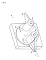
FIG. 2 ] It is a figure illustrating a configuration of a fiberbundle supply device 32. - [
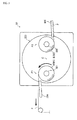
FIG. 3 ] It is a figure illustrating a state in which a fiber bundle F wound around a first bobbin B1 is unwound. - [
Fig. 4 ] It is a figure illustrating a state in which rotation of aturntable 323 is started. - [
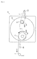
Fig. 5 ] It is a figure illustrating a state in which rotation of theturntable 323 is terminated. - [
Fig. 6 ] It is a figure illustrating a state in which an overlapped portion of the fiber bundle F is spliced by asplicing device 326. - [
Fig. 7 ] It is a figure illustrating a state in which the fiber bundle F unwound from the first bobbin B1 is cut by acutter device 327. - [
Fig. 8 ] It is a figure illustrating a state in which rotation of theturntable 323 to the reverse direction is terminated. - [
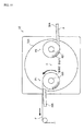
Fig. 9 ] It is a figure illustrating a state in which the fiber bundle F wound around a second bobbin B2 is unwound. - [
Fig. 10 ] It is a figure illustrating a state in which a new bobbin B is fitted to a firstbobbin holder shaft 321. - [
Fig. 11 ] It is a figure illustrating a state in which the fiber bundle F is restricted in a prescribed trajectory. - [
Fig. 12 ] It is a figure illustrating a state in which the fiber bundle F of the first bobbin B1 is superposed on the fiber bundle F of the second bobbin B2. -
- 1
- liner
- 10
- liner transfer part
- 11
- pedestal
- 12
- liner support frame
- 13
- rotational shaft
- 20
- helical winding part
- 21
- pedestal
- 22
- helical head
- 23
- guide
- 30
- fiber bundle supply part
- 31
- rack
- 32
- fiber bundle supply device
- 321
- first bobbin holder shaft
- 322
- second bobbin holder shaft
- 323
- turntable
- 324
- first fiber bundle guide
- 325
- second fiber bundle guide
- B
- bobbin
- B1
- first bobbin
- B2
- second bobbin
- C
- central axis
- F
- fiber bundle
- P1
- unwinding position
- P2
- standby position
- Next, an explanation will be given of embodiments of the present invention.
- A fiber
bundle supply device 32 according to the embodiment of the present invention is included in a fiberbundle supply part 30 which configures afilament winding device 100. Therefore, first of all, a brief explanation will be given of an overall configuration of the filament winding device 100 (Hereinafter referred to as "FW device 100"). -
FIG. 1 illustrates the overall configuration of theFW device 100. An arrow D in the drawing indicates a transfer direction of a liner 1. The direction in parallel to the transfer direction of the liner 1 is regarded as the longitudinal direction of theFW device 100, and one direction of transferring the liner 1 and other direction opposite thereto are respectively defined as the front side and the rear side. TheFW device 100 reciprocates the liner 1 in the longitudinal direction, whereby the front side and the rear side is defined depending on the transfer direction of the liner 1. - The
FW device 100 winds a fiber bundle F around the outer periphery surface of the liner 1. TheFW device 100 mainly includes aliner transfer part 10, a helical windingpart 20, and the fiberbundle supply part 30. - The
liner transfer part 10 transfers the liner 1 while rotating it. In particular, the liner 1 is rotated about the longitudinal direction of theFW device 100 as a center axis, and is transferred in the longitudinal direction of theFW device 100 by theliner transfer part 10. Theliner transfer part 10 mainly includes a pedestal 11, liner support frames 12, and arotational shaft 13. - The pedestal 11 is placed on a pair of rails extending in the longitudinal direction of the
FW device 100. The pedestal 11 is provided with the pair of liner support frames 12 and therotational shaft 13. The liner 1 is attached to therotational shaft 13 and is rotated one direction via a power mechanism (not shown). - Because of this configuration, it is possible that the liner 1 is rotated about the longitudinal direction of the
FW device 100 as a center axis, and is transferred in the longitudinal direction of theFW device 100 by theliner transfer part 10. - The helical winding
part 20 winds the fiber bundles F around the outer periphery surface of the liner 1. In particular, the helical windingpart 20 performs so-called helical winding in which the winding angle of the fiber bundle F is set to be a prescribed value relative to the longitudinal direction of theFW device 100. The helical windingpart 20 mainly includes apedestal 21 and ahelical head 22. - The
pedestal 21 is provided with thehelical head 22. Thehelical head 22 is provided with a plurality ofguides 23 each of which guides the fiber bundle F. The fiber bundle F guided by eachguide 23 is wound around the outer periphery surface of the liner 1 passing through while rotating. - Because of this configuration, it is possible that the helical winding
part 20 performs so-called helical winding, where the winding angle of the fiber bundle F is set to be the prescribed value relative to the longitudinal direction of theFW device 100. - The fiber
bundle supply part 30 supplies the fiber bundles F to the helical winding part. In particular, the fiberbundle supply part 30 supplies the fiber bundle F to each guide 23 of thehelical head 22 included in the helical windingpart 20. The fiberbundle supply part 30 mainly includes arack 31 and the fiberbundle supply devices 32. - The
rack 31 is provided with the plurality of fiberbundle supply devices 32. The fiberbundle supply device 32 supports bobbins B around which the fiber bundle F is wound. And the fiber bundle F wound around each bobbin B is supplied to the correspondingrespective guide 23 through a guide member (not shown). - Because of this configuration, it is possible that the fiber bundle F is fed to each guide 23 of the
helical head 22 included in the helical windingpart 20 by the fiberbundle supply part 30. - Next, a detailed explanation will be given of the configuration of the fiber
bundle supply device 32. -
FIG. 2 illustrates the configuration of the fiberbundle supply device 32. Here, explanation will be given by using the case of two-shaft type fiber bundle supply device which has twobobbin holder shafts - If the fiber bundle F wound around one bobbin B has been unwound and little remains, the fiber
bundle supply device 32 starts unwinding of the fiber bundle F wound around the other bobbin B, whereby the fiber bundle F is continuously supplied. The fiberbundle supply device 32 mainly includes the firstbobbin holder shaft 321, the secondbobbin holder shaft 322, aturntable 323, a firstfiber bundle guide 324, and a secondfiber bundle guide 325. Here, the bobbin B supported by the firstbobbin holder shaft 321 is defined as the first bobbin B1, whereas the bobbin B supported by the secondbobbin holder shaft 322 is defined as the second bobbin B2. - The first
bobbin holder shaft 321 rotatably supports the first bobbin B1. When the fiber bundle F is pulled, the first bobbin B1 rotates, whereby the fiber bundle F is unwound. When the firstbobbin holder shaft 321 is at an unwinding position P1, the fiber bundle F wound around the first bobbin B1 is unwound (see the black arrows inFIG. 3 ). And, as explained above, the fiber bundle F unwound from the first bobbin B1 is supplied to thecorresponding guide 23 of thehelical head 22. - The second
bobbin holder shaft 322 rotatably supports the second bobbin B2. When the fiber bundle F is pulled, the second bobbin B2 rotates, whereby the fiber bundle F is unwound. When the secondbobbin holder shaft 322 is at the unwinding position P1, the fiber bundle F wound around the second bobbin B2 is unwound (see the black arrows inFIG. 9 ). And, as explained above, the fiber bundle F unwound from the second bobbin B2 is supplied to thecorresponding guide 23 of thehelical head 22. - The defined discrimination between the first
bobbin holder shaft 321 and the secondbobbin holder shaft 322 is made for the purpose of illustration, and each of these shafts has the same configuration. - The first
bobbin holder shaft 321 and the secondbobbin holder shaft 322 are arranged on a concentric circle on theturntable 323, and theturntable 323 rotates around the central axis C of said concentric circle. When theturntable 323 is rotated around the central axis C by about 180°, the position of the firstbobbin holder shaft 321 at the unwinding position P1 and the position of the secondbobbin holder shaft 322 at a standby position P2 are switched with each other (seeFIG. 5 ). When the secondbobbin holder shaft 322 is at the unwinding position P1 and the firstbobbin holder shaft 321 is at the standby position P2, the position of the secondbobbin holder shaft 322 at the unwinding position P1 and the position of the firstbobbin holder shaft 321 at the standby position P2 are exchanged with each other. - The first
fiber bundle guide 324 is installed on theturntable 323 and is rotated with theturntable 323. When theturntable 323 starts rotation, the firstfiber bundle guide 324 guides the fiber bundle F unwound from the first bobbin B1 to be restricted in a prescribed trajectory (seeFIG. 4 ,FIG. 11 ). When the firstbobbin holder shaft 321 is at the standby position P2 and the firstbobbin holder shaft 321 is exchanged with the secondbobbin holder shaft 322 which is at the unwinding position P1, the end portion of the fiber bundle F wound around the first bobbin B1 is superposed on the fiber bundle F unwound from the second bobbin B2. Specific configuration will be explained later. - The second
fiber bundle guide 325 is installed on theturntable 323 and is rotated with theturntable 323. When the rotation of theturntable 323 is terminated, the secondfiber bundle guide 325 superposes the end portion of the fiber bundle F wound around the second bobbin B2 on the fiber bundle F unwound from the first bobbin B1 (seeFIG. 5 ,FIG. 12 ). When the secondbobbin holder shaft 322 is at the unwinding position P1 and the secondbobbin holder shaft 322 is switched with the firstbobbin holder shaft 321 which is at the standby position P2, the fiber bundle F unwound from the second bobbin B2 is guided to be restricted in the prescribed trajectory. Specific configuration will be explained later. - The defined discrimination between the first
fiber bundle guide 324 and the secondfiber bundle guide 325 is made for the purpose of illustration, and each of these guides each has the same configuration. - Next, explanation will be given of an operation mode of the fiber
bundle supply device 32 at the time of changing a bobbin. -
FIG. 3 to FIG. 10 illustrate an example of operation of the fiberbundle supply device 32 at the time of changing a bobbin. The black arrows in the drawings indicate the rotation direction of the first bobbin B1 and the second bobbin B2 and the sending-out direction of the fiber bundle F. The white arrows in the drawings indicate the rotation direction of theturntable 323. Here, explanation will be given by assuming the case in which the firstbobbin holder shaft 321 is at the unwinding position P1 and the secondbobbin holder shaft 322 is at the standby position P2. -
FIG. 3 illustrates a state in which the fiber bundle F wound around the first bobbin B1 is unwound. As shown inFIG. 3 , when the fiber bundle F is pulled, the first bobbin B1 rotates, whereby the fiber bundle F is unwound. Since the fiber bundle F is momentarily unwound from the first bobbin B1, the remaining amount of the fiber bundle F wound around the first bobbin B1 gradually decreases. Therefore, the first bobbin B1 has to be changed to the second bobbin B2 before all of the fiber bundle F wound around the first bobbin B1 is unwound and the first bobbin B1 becomes empty. -
FIG. 4 illustrates a state in which theturntable 323 starts rotation. As shown inFIG. 4 , when theturntable 323 starts rotation, the firstfiber bundle guide 324 pushes up the fiber bundle F unwound from the first bobbin B1. At this time, the firstfiber bundle guide 324 guides the fiber bundle F unwound from the first bobbin B1 to be restricted in the prescribed trajectory. - Specifically, as shown in
FIG. 11 , the firstfiber bundle guide 324 includes a pair ofguide walls 324a which gradually become narrow along the feeding direction of the fiber bundle F. When the fiber bundle F is pushed up, theguide walls 324a lead the fiber bundle F to abottom wall 324b. Then, the fiber bundle F unwound from the first bobbin B1 is guided by theguide walls 324a and thebottom wall 324b and sent out from afiber bundle passage 324c which is arranged at an end portion. Thus, the firstfiber bundle guide 324 guides the fiber bundle F traversed (see "T" in the drawing) in the shaft direction of the first bobbin B1 to be restricted in the prescribed trajectory. -
FIG. 5 illustrates a state in which the rotation of theturntable 323 is terminated. As shown inFIG. 5 , when the rotation of theturntable 323 is terminated, the secondfiber bundle guide 325 comes in contact with the fiber bundle F unwound from the first bobbin B1. At this time, the secondfiber bundle guide 325 superposes the end portion of the fiber bundle F wound around the second bobbin B2 on the fiber bundle F unwound from the first bobbin B1. - Specifically, as shown in
FIG. 12 , the secondfiber bundle guide 325 includes aholder 325d which holds the tip end portion of the fiber bundle F. Theholder 325d retains the fiber bundle F wound around the second bobbin B2 in such a state to run along abottom wall 325b. Then, by rotating theturntable 323, the fiber bundle F wound around the second bobbin B2 is guided in such a state to run along the fiber bundle F unwound from the first bobbin B1. As such, the secondfiber bundle guide 325 superposes the end portion of the fiber bundle F wound around the second bobbin B2 on the fiber bundle F unwound from the first bobbin B1. - Because of this configuration, it is possible that the end portion of the fiber bundle F wound around the second bobbin B2 is overlapped with the fiber bundle F unwound from the first bobbin B1 and restricted in the prescribed trajectory by the present fiber
bundle supply device 32. As such, the fiber bundle F of the first bobbin B1 can be spliced with the fiber bundle F of the second bobbin B2. -
FIG. 6 illustrates a state where overlapped portions of the fiber bundle F are spliced by asplicing device 326. As shown inFIG. 6 , with respect to thesplicing device 326, the overlapped portion of the fiber bundle F is nipped and held by thesplicing device 326 and the secondfiber bundle guide 325. Then thesplicing device 326 applies heat to the overlapped portion of the fiber bundles F, whereby these fiber bundles F are spliced. - Specifically, the
splicing device 326 includes aheater part 326a which becomes hot due to a flow of electric current. Theheater part 326a applies heat to the overlapped portion of the fiber bundles F, whereby each of the fiber bundles F are thermally-cured and spliced. As such, the fiber bundle F of the first bobbin B1 can be surely spliced with the fiber bundle F of the second bobbin B2 by thesplicing device 326 with a simple configuration. - As other component, the overlapped portion of the fiber bundles F may be depressed and spliced by the
splicing device 326. Moreover, the overlapped portion of the fiber bundles F may be stitched up and spliced by thesplicing device 326. As such, the fiber bundle F of the first bobbin B1 can be surely spliced with the fiber bundle F of the second bobbin B2 by thesplicing device 326 with a simple configuration. Also, each of the fiber bundles F may be spliced by using other methods such as confounding etc. - Because of this configuration, it is possible that the overlapped portion of the fiber bundle F of the first bobbin B1 and the fiber bundle F of the second bobbin B2 are spliced by the fiber
bundle supply device 32. Accordingly, the fiber bundle F of the first bobbin B1 can be surely spliced with the fiber bundle F of the second bobbin B2. - Furthermore, the fiber
bundle supply device 32 sends out the fiber bundle F while splicing the fiber bundle F of the first bobbin B1 and the fiber bundle F of the second bobbin B2. This makes it possible to easily change the length of the splicing portion and the splicing pattern. As such, it is also possible to secure the flexibility of the splicing portion by intermittently splicing the overlapped portion of the fiber bundle F. -
FIG. 7 illustrates a state where the fiber bundle F unwound from the first bobbin B1 is cut by acutter device 327. As shown inFIG. 7 , thecutter device 327 divides the fiber bundle F unwound from the first bobbin B1 between the first bobbin B1 and the second bobbin B2. - Specifically, the
cutter device 327 includes acutter 327a which cuts the fiber bundle F. The fiber bundle F unwound from the first bobbin B1 spanned between the first bobbin B1 and the second bobbin B2 is divided by thecutter 327a. The time that the fiber bundle F is cut is determined based on the bonding strength required for the splicing portion. That is to say, the fiber bundle F is cut by thecutter device 327 such that the fiber bundle F would not separate even when the tensile load is applied to the fiber bundle F when all of the overlapped portion of the fiber bundle F is spliced, and prevent the length of the splicing portion from being longer than necessary. - Because of this configuration, it is possible that necessary and sufficient bonding strength is secured with respect to the splicing portion of the fiber bundle F of the first bobbin B1 and the fiber bundle F of the second bobbin B2 by the fiber
bundle supply device 32. Accordingly, required bonding strength can be secured for the splicing portion, and time required for splicing can be shortened. -
FIG. 8 illustrates a state where rotation of theturntable 323 to the reverse direction is terminated. As shown inFIG. 8 , the secondfiber bundle guide 325 is rotated to the reverse direction with theturntable 323, whereby the secondfiber bundle guide 325 is separated from the fiber bundle F of the second bobbin B2. -
FIG. 9 illustrates a state where the fiber bundle F wound around the second bobbin B2 is unwound. As shown inFIG. 9 , when the fiber bundle F is pulled, the second bobbin B2, rotates, whereby the fiber bundle F is unwound. Since the fiber bundle F is momentarily unwound from the second bobbin B2, the remaining amount of the fiber bundle F wound around the second bobbin B2, gradually decreases. Therefore, the second bobbin B2 has to be changed to the first bobbin B1 by fitting a new bobbin B (first bobbin B1) to the firstbobbin holder shaft 321 before all of the fiber bundle F wound around the second bobbin B2 is unwound and the second bobbin B2 becomes an empty bobbin. -
FIG. 10 illustrates a state where a new bobbin B (first bobbin B1) is fitted to the firstbobbin holder shaft 321. As shown inFIG. 10 , by fitting the new bobbin B (first bobbin B1) to the firstbobbin holder shaft 321, the bobbin B (first bobbin B1) can be kept at a standby. As such, if the fiber bundle F wound around the second bobbin B2 has been unwound and little remains, unwinding of the fiber bundle F wound around the new bobbin B (first bobbin B1) is started, whereby the fiber bundle F is continuously supplied. - As described above, with respect to the fiber
bundle supply device 32 according to the embodiment of the present invention, if the fiber bundle F wound around the first bobbin B1 has been unwound and little remains, unwinding of the fiber bundle F wound around the second bobbin B2 is started, whereby the fiber bundle F is continuously supplied. And if the fiber bundle F wound around the second bobbin B2 has been unwound and little remains, unwinding of the fiber bundle F wound around the first bobbin B1 is started, whereby the fiber bundle F is continuously supplied. As such, the fiber bundle F can be continuously supplied. - The present invention can be utilized to a technique of a fiber bundle supply device.
Claims (4)
- A fiber bundle supply device comprising:plural bobbin holder shafts each of which supports a bobbin around which a fiber bundle is wound; anda turntable on which the bobbin holder shafts are arranged in a concentric pattern and which rotates around the central axis of said concentric circle,characterized in thatthe bobbin holder shafts are configured from at least a first bobbin holder shaft which supports a first bobbin, and a second bobbin holder shaft which supports a second bobbin, whereinif the fiber bundle wound around the first bobbin has been unwound and little remains, by rotating the turntable and splicing the fiber bundle of the first bobbin and the fiber bundle of the second bobbin, unwinding of the fiber bundle wound around the second bobbin is started.
- The fiber bundle supply device according to Claim 1, characterized by comprising a first fiber bundle guide and a second fiber bundle guide which are installed on the turntable and which rotate with the turntable, wherein
when the turntable starts rotation, the first fiber bundle guide guides the fiber bundle unwound from the first bobbin to be restricted in a prescribed trajectory,
and when the rotation of the turntable is terminated, the second fiber bundle guide superposes the end portion of the fiber bundle wound around the second bobbin on the fiber bundle unwound from the first bobbin. - The fiber bundle supply device according to Claim 1 or Claim 2 characterized by comprising a splicing device which splices the fiber bundle of the first bobbin and the fiber bundle of the second bobbin together, wherein
the splicing device splices the overlapped portion of the fiber bundle of the first bobbin and the fiber bundle of the second bobbin. - The fiber bundle supply device according to any one of Claim 1 to Claim 3, characterized by comprising a cutter device which cuts the fiber bundle unwound from the first bobbin, wherein
the cutter device cuts the fiber bundle unwound from the first bobbin such that necessary and sufficient bonding strength is obtained when all of the overlapped portion of the fiber bundle is spliced.
Applications Claiming Priority (2)
| Application Number | Priority Date | Filing Date | Title |
|---|---|---|---|
| JP2011203683A JP5809899B2 (en) | 2011-09-16 | 2011-09-16 | Fiber bundle feeder |
| PCT/JP2012/073490 WO2013039157A1 (en) | 2011-09-16 | 2012-09-13 | Fiber bundle supply device |
Publications (4)
| Publication Number | Publication Date |
|---|---|
| EP2757062A1 true EP2757062A1 (en) | 2014-07-23 |
| EP2757062A4 EP2757062A4 (en) | 2015-04-22 |
| EP2757062B1 EP2757062B1 (en) | 2017-03-22 |
| EP2757062B8 EP2757062B8 (en) | 2017-05-31 |
Family
ID=47883374
Family Applications (1)
| Application Number | Title | Priority Date | Filing Date |
|---|---|---|---|
| EP12832445.6A Active EP2757062B8 (en) | 2011-09-16 | 2012-09-13 | Fiber bundle supply device |
Country Status (5)
| Country | Link |
|---|---|
| US (1) | US20140346270A1 (en) |
| EP (1) | EP2757062B8 (en) |
| JP (1) | JP5809899B2 (en) |
| CN (1) | CN103796939B (en) |
| WO (1) | WO2013039157A1 (en) |
Cited By (6)
| Publication number | Priority date | Publication date | Assignee | Title |
|---|---|---|---|---|
| WO2017065784A1 (en) * | 2015-10-16 | 2017-04-20 | Avent, Inc. | Method and system for splicing nose wire in a facemask manufacturing process |
| US10786020B2 (en) | 2015-10-16 | 2020-09-29 | O&M Halyard, Inc. | Method and system for placing pre-cut nose wires in a facemask manufacturing process |
| US10828842B2 (en) | 2015-10-16 | 2020-11-10 | O&M Halyard, Inc. | Method and system for cutting and placing nose wires in a facemask manufacturing process |
| US10882715B2 (en) | 2015-10-16 | 2021-01-05 | O&M Halyard, Inc. | Method and system for splicing nose wire in a facemask manufacturing process |
| US10913559B2 (en) | 2015-10-16 | 2021-02-09 | O&M Halyard, Inc. | Method and system for automated stacking and loading wrapped facemasks into a carton in a manufacturing line |
| US11059690B2 (en) | 2015-10-16 | 2021-07-13 | O&M Halyard, Inc. | Method and system for automated stacking and loading of wrapped facemasks into a carton in a manufacturing line |
Families Citing this family (10)
| Publication number | Priority date | Publication date | Assignee | Title |
|---|---|---|---|---|
| CN105293189A (en) * | 2014-08-02 | 2016-02-03 | 博尔富(江苏)实业有限公司 | Thermal treatment double-station uninterrupted unwinding device |
| CN104444564B (en) * | 2014-12-11 | 2017-12-05 | 遵义天义利威机电有限责任公司 | It is a kind of to be applied to put device dividing for copper wire |
| DE102017200535A1 (en) * | 2016-01-20 | 2017-07-20 | Adient Luxembourg Holding S.à.r.l. | Method for producing a component |
| CN105619772A (en) * | 2016-03-14 | 2016-06-01 | 东南大学 | Rod-shaped carbon fibre winding mechanism device with hollow wheel structure |
| JP6954018B2 (en) | 2017-11-09 | 2021-10-27 | トヨタ自動車株式会社 | Equipment and method for joining the first fiber impregnated with resin and the second fiber |
| JP7078908B2 (en) * | 2019-04-17 | 2022-06-01 | トヨタ自動車株式会社 | Fiber bundle supply device |
| CN112441467B (en) * | 2020-11-25 | 2023-02-17 | 国网山东省电力公司东平县供电公司 | BV line unwrapping wire ware |
| US12583193B2 (en) | 2021-03-26 | 2026-03-24 | Mitsui Chemicals, Inc. | Production apparatus for producing a fiber-reinforced resin and a production method for producing a fiber-reinforced resin |
| EP4316767A4 (en) * | 2021-03-26 | 2025-03-19 | Mitsui Chemicals, Inc. | Apparatus for producing a fiber-reinforced resin and method for producing a fiber-reinforced resin |
| CN117735338A (en) * | 2023-12-22 | 2024-03-22 | 五河群英纺织品有限公司 | A winding machine with automatic bobbin changing |
Family Cites Families (14)
| Publication number | Priority date | Publication date | Assignee | Title |
|---|---|---|---|---|
| JPS6029190A (en) * | 1983-07-23 | 1985-02-14 | 蛇の目ミシン工業株式会社 | Yarn connecting method and apparatus of sewing machine |
| US4887649A (en) * | 1987-06-25 | 1989-12-19 | Sulzer Brothers Limited | Weft bobbin changer for a loom |
| DE3808957A1 (en) * | 1988-03-17 | 1989-09-28 | Mayer Fa Karl | SPECIAL REELING MACHINE |
| JPH0455002Y2 (en) * | 1989-08-14 | 1992-12-24 | ||
| JPH04100954A (en) * | 1990-08-10 | 1992-04-02 | Tsudakoma Corp | Changing of weft in loom |
| JPH04241140A (en) * | 1991-01-16 | 1992-08-28 | Toyota Autom Loom Works Ltd | Yarn feeding stand in shuttle-less weaving machine |
| JPH0733203B2 (en) * | 1992-08-04 | 1995-04-12 | 宮崎鉄工株式会社 | Pick-up wire feeder |
| JPH09176942A (en) * | 1995-12-26 | 1997-07-08 | Murata Mach Ltd | Treating system for yarn |
| DE10029492C2 (en) * | 2000-06-15 | 2003-04-24 | Mayer Textilmaschf | Warping plant and warping process |
| EP1496003B1 (en) * | 2003-07-11 | 2006-03-22 | Schärer Schweiter Mettler AG | Automatic bobbin changer for an automatic winding machine |
| JP2005154104A (en) * | 2003-11-27 | 2005-06-16 | Murata Mach Ltd | Thread take-up device and sensor with needle |
| JP4292285B2 (en) * | 2004-07-02 | 2009-07-08 | サカイオーベックス株式会社 | Belt-like weft supply device and method |
| JP2009155066A (en) * | 2007-12-27 | 2009-07-16 | Toray Ind Inc | Revolving type yarn winding method and apparatus |
| JP5578304B2 (en) * | 2008-06-20 | 2014-08-27 | 村田機械株式会社 | Fiber bundle tension management system and filament bundle tension management method in filament winding apparatus |
-
2011
- 2011-09-16 JP JP2011203683A patent/JP5809899B2/en active Active
-
2012
- 2012-09-13 WO PCT/JP2012/073490 patent/WO2013039157A1/en not_active Ceased
- 2012-09-13 CN CN201280044823.3A patent/CN103796939B/en active Active
- 2012-09-13 EP EP12832445.6A patent/EP2757062B8/en active Active
- 2012-09-13 US US14/345,077 patent/US20140346270A1/en not_active Abandoned
Cited By (7)
| Publication number | Priority date | Publication date | Assignee | Title |
|---|---|---|---|---|
| WO2017065784A1 (en) * | 2015-10-16 | 2017-04-20 | Avent, Inc. | Method and system for splicing nose wire in a facemask manufacturing process |
| US10494221B2 (en) | 2015-10-16 | 2019-12-03 | O&M Halyard, Inc. | Method and system for splicing nose wire in a facemask manufacturing process |
| US10786020B2 (en) | 2015-10-16 | 2020-09-29 | O&M Halyard, Inc. | Method and system for placing pre-cut nose wires in a facemask manufacturing process |
| US10828842B2 (en) | 2015-10-16 | 2020-11-10 | O&M Halyard, Inc. | Method and system for cutting and placing nose wires in a facemask manufacturing process |
| US10882715B2 (en) | 2015-10-16 | 2021-01-05 | O&M Halyard, Inc. | Method and system for splicing nose wire in a facemask manufacturing process |
| US10913559B2 (en) | 2015-10-16 | 2021-02-09 | O&M Halyard, Inc. | Method and system for automated stacking and loading wrapped facemasks into a carton in a manufacturing line |
| US11059690B2 (en) | 2015-10-16 | 2021-07-13 | O&M Halyard, Inc. | Method and system for automated stacking and loading of wrapped facemasks into a carton in a manufacturing line |
Also Published As
| Publication number | Publication date |
|---|---|
| EP2757062B1 (en) | 2017-03-22 |
| JP5809899B2 (en) | 2015-11-11 |
| JP2013063823A (en) | 2013-04-11 |
| WO2013039157A1 (en) | 2013-03-21 |
| CN103796939B (en) | 2016-05-11 |
| EP2757062A4 (en) | 2015-04-22 |
| EP2757062B8 (en) | 2017-05-31 |
| CN103796939A (en) | 2014-05-14 |
| US20140346270A1 (en) | 2014-11-27 |
Similar Documents
| Publication | Publication Date | Title |
|---|---|---|
| EP2757062B1 (en) | Fiber bundle supply device | |
| KR101453231B1 (en) | Method for producing hollow fiber membrane sheet-like object, method for producing hollow fiber membrane module, and device for producing hollow fiber membrane sheet-like object | |
| EP2684827A2 (en) | A drum inter-storage of yarn at an operating unit of a textile machine and method of controlling it | |
| US10087027B2 (en) | Tape supplying method and tape supplying device | |
| EP2186765B1 (en) | Take-up winding facility | |
| US10007079B2 (en) | Optical fiber unit and optical fiber cable | |
| US10266363B2 (en) | Microduct-tube winder, double station winder, processing system for empty plastics microduct tubes and method for winding up such tubes | |
| EP2671830B1 (en) | Textile machine, standby position determining method of driven member of winding unit, and winding unit | |
| EP2644548B1 (en) | Take-up apparatus and take-up facility | |
| CN107161800B (en) | Produce the Yarn twisting device of the station of the weaving loom of cross winding bobbin | |
| CN106465569B (en) | Tape spool turret arrangement for tape-and-reel machines | |
| EP3168665A1 (en) | Optical fiber unit manufacturing method and manufacturing device | |
| US9469066B2 (en) | Filament winding apparatus | |
| EP2757063B1 (en) | Bobbin unwinding device of filament winding device | |
| CN107735192A (en) | The manufacture method of wire rod twisting device and twisted wire | |
| EP3369543B1 (en) | Wire replacement device and wire replacement method | |
| CN107954270A (en) | Pallet distributor | |
| JP2014227249A (en) | Yarn winder | |
| TWI548583B (en) | Tape supply device | |
| CN105555693B (en) | The manufacture method of fibre bundle | |
| EP3663244A1 (en) | Paper sheet storage device | |
| JP6170953B2 (en) | Tape supply method and tape supply apparatus | |
| US10338333B2 (en) | Device and method for inserting an optical fiber onto a bobbin | |
| JP5363553B2 (en) | Partial warping machine for patterned warp | |
| US9522505B2 (en) | Fiber bundle processing device |
Legal Events
| Date | Code | Title | Description |
|---|---|---|---|
| PUAI | Public reference made under article 153(3) epc to a published international application that has entered the european phase |
Free format text: ORIGINAL CODE: 0009012 |
|
| 17P | Request for examination filed |
Effective date: 20140320 |
|
| AK | Designated contracting states |
Kind code of ref document: A1 Designated state(s): AL AT BE BG CH CY CZ DE DK EE ES FI FR GB GR HR HU IE IS IT LI LT LU LV MC MK MT NL NO PL PT RO RS SE SI SK SM TR |
|
| DAX | Request for extension of the european patent (deleted) | ||
| RA4 | Supplementary search report drawn up and despatched (corrected) |
Effective date: 20150319 |
|
| RIC1 | Information provided on ipc code assigned before grant |
Ipc: B65H 49/32 20060101ALI20150313BHEP Ipc: B29C 70/16 20060101ALI20150313BHEP Ipc: B65H 49/16 20060101ALI20150313BHEP Ipc: B29C 53/60 20060101ALI20150313BHEP Ipc: B65H 57/04 20060101ALI20150313BHEP Ipc: B65H 57/06 20060101ALI20150313BHEP Ipc: B65H 67/048 20060101ALI20150313BHEP Ipc: B65H 49/28 20060101AFI20150313BHEP Ipc: B65H 67/02 20060101ALI20150313BHEP Ipc: B29C 31/04 20060101ALI20150313BHEP Ipc: B29C 53/80 20060101ALI20150313BHEP |
|
| GRAP | Despatch of communication of intention to grant a patent |
Free format text: ORIGINAL CODE: EPIDOSNIGR1 |
|
| INTG | Intention to grant announced |
Effective date: 20161012 |
|
| RIN1 | Information on inventor provided before grant (corrected) |
Inventor name: TANIGAWA MOTOHIRO Inventor name: HATTA KEN Inventor name: NAKAMURA DAIGORO |
|
| GRAS | Grant fee paid |
Free format text: ORIGINAL CODE: EPIDOSNIGR3 |
|
| GRAA | (expected) grant |
Free format text: ORIGINAL CODE: 0009210 |
|
| AK | Designated contracting states |
Kind code of ref document: B1 Designated state(s): AL AT BE BG CH CY CZ DE DK EE ES FI FR GB GR HR HU IE IS IT LI LT LU LV MC MK MT NL NO PL PT RO RS SE SI SK SM TR |
|
| REG | Reference to a national code |
Ref country code: GB Ref legal event code: FG4D |
|
| REG | Reference to a national code |
Ref country code: CH Ref legal event code: EP |
|
| REG | Reference to a national code |
Ref country code: AT Ref legal event code: REF Ref document number: 877512 Country of ref document: AT Kind code of ref document: T Effective date: 20170415 |
|
| RAP2 | Party data changed (patent owner data changed or rights of a patent transferred) |
Owner name: TOYOTA JIDOSHA KABUSHIKI KAISHA Owner name: MURATA MACHINERY, LTD. |
|
| REG | Reference to a national code |
Ref country code: IE Ref legal event code: FG4D |
|
| REG | Reference to a national code |
Ref country code: DE Ref legal event code: R096 Ref document number: 602012030273 Country of ref document: DE |
|
| REG | Reference to a national code |
Ref country code: NL Ref legal event code: MP Effective date: 20170322 |
|
| PG25 | Lapsed in a contracting state [announced via postgrant information from national office to epo] |
Ref country code: GR Free format text: LAPSE BECAUSE OF FAILURE TO SUBMIT A TRANSLATION OF THE DESCRIPTION OR TO PAY THE FEE WITHIN THE PRESCRIBED TIME-LIMIT Effective date: 20170623 Ref country code: FI Free format text: LAPSE BECAUSE OF FAILURE TO SUBMIT A TRANSLATION OF THE DESCRIPTION OR TO PAY THE FEE WITHIN THE PRESCRIBED TIME-LIMIT Effective date: 20170322 Ref country code: HR Free format text: LAPSE BECAUSE OF FAILURE TO SUBMIT A TRANSLATION OF THE DESCRIPTION OR TO PAY THE FEE WITHIN THE PRESCRIBED TIME-LIMIT Effective date: 20170322 Ref country code: NO Free format text: LAPSE BECAUSE OF FAILURE TO SUBMIT A TRANSLATION OF THE DESCRIPTION OR TO PAY THE FEE WITHIN THE PRESCRIBED TIME-LIMIT Effective date: 20170622 Ref country code: LT Free format text: LAPSE BECAUSE OF FAILURE TO SUBMIT A TRANSLATION OF THE DESCRIPTION OR TO PAY THE FEE WITHIN THE PRESCRIBED TIME-LIMIT Effective date: 20170322 |
|
| REG | Reference to a national code |
Ref country code: LT Ref legal event code: MG4D |
|
| REG | Reference to a national code |
Ref country code: AT Ref legal event code: MK05 Ref document number: 877512 Country of ref document: AT Kind code of ref document: T Effective date: 20170322 |
|
| PG25 | Lapsed in a contracting state [announced via postgrant information from national office to epo] |
Ref country code: LV Free format text: LAPSE BECAUSE OF FAILURE TO SUBMIT A TRANSLATION OF THE DESCRIPTION OR TO PAY THE FEE WITHIN THE PRESCRIBED TIME-LIMIT Effective date: 20170322 Ref country code: RS Free format text: LAPSE BECAUSE OF FAILURE TO SUBMIT A TRANSLATION OF THE DESCRIPTION OR TO PAY THE FEE WITHIN THE PRESCRIBED TIME-LIMIT Effective date: 20170322 Ref country code: BG Free format text: LAPSE BECAUSE OF FAILURE TO SUBMIT A TRANSLATION OF THE DESCRIPTION OR TO PAY THE FEE WITHIN THE PRESCRIBED TIME-LIMIT Effective date: 20170622 Ref country code: SE Free format text: LAPSE BECAUSE OF FAILURE TO SUBMIT A TRANSLATION OF THE DESCRIPTION OR TO PAY THE FEE WITHIN THE PRESCRIBED TIME-LIMIT Effective date: 20170322 |
|
| PG25 | Lapsed in a contracting state [announced via postgrant information from national office to epo] |
Ref country code: NL Free format text: LAPSE BECAUSE OF FAILURE TO SUBMIT A TRANSLATION OF THE DESCRIPTION OR TO PAY THE FEE WITHIN THE PRESCRIBED TIME-LIMIT Effective date: 20170322 |
|
| PG25 | Lapsed in a contracting state [announced via postgrant information from national office to epo] |
Ref country code: SK Free format text: LAPSE BECAUSE OF FAILURE TO SUBMIT A TRANSLATION OF THE DESCRIPTION OR TO PAY THE FEE WITHIN THE PRESCRIBED TIME-LIMIT Effective date: 20170322 Ref country code: CZ Free format text: LAPSE BECAUSE OF FAILURE TO SUBMIT A TRANSLATION OF THE DESCRIPTION OR TO PAY THE FEE WITHIN THE PRESCRIBED TIME-LIMIT Effective date: 20170322 Ref country code: ES Free format text: LAPSE BECAUSE OF FAILURE TO SUBMIT A TRANSLATION OF THE DESCRIPTION OR TO PAY THE FEE WITHIN THE PRESCRIBED TIME-LIMIT Effective date: 20170322 Ref country code: IT Free format text: LAPSE BECAUSE OF FAILURE TO SUBMIT A TRANSLATION OF THE DESCRIPTION OR TO PAY THE FEE WITHIN THE PRESCRIBED TIME-LIMIT Effective date: 20170322 Ref country code: RO Free format text: LAPSE BECAUSE OF FAILURE TO SUBMIT A TRANSLATION OF THE DESCRIPTION OR TO PAY THE FEE WITHIN THE PRESCRIBED TIME-LIMIT Effective date: 20170322 Ref country code: AT Free format text: LAPSE BECAUSE OF FAILURE TO SUBMIT A TRANSLATION OF THE DESCRIPTION OR TO PAY THE FEE WITHIN THE PRESCRIBED TIME-LIMIT Effective date: 20170322 Ref country code: EE Free format text: LAPSE BECAUSE OF FAILURE TO SUBMIT A TRANSLATION OF THE DESCRIPTION OR TO PAY THE FEE WITHIN THE PRESCRIBED TIME-LIMIT Effective date: 20170322 |
|
| PG25 | Lapsed in a contracting state [announced via postgrant information from national office to epo] |
Ref country code: IS Free format text: LAPSE BECAUSE OF FAILURE TO SUBMIT A TRANSLATION OF THE DESCRIPTION OR TO PAY THE FEE WITHIN THE PRESCRIBED TIME-LIMIT Effective date: 20170722 Ref country code: PT Free format text: LAPSE BECAUSE OF FAILURE TO SUBMIT A TRANSLATION OF THE DESCRIPTION OR TO PAY THE FEE WITHIN THE PRESCRIBED TIME-LIMIT Effective date: 20170724 Ref country code: PL Free format text: LAPSE BECAUSE OF FAILURE TO SUBMIT A TRANSLATION OF THE DESCRIPTION OR TO PAY THE FEE WITHIN THE PRESCRIBED TIME-LIMIT Effective date: 20170322 Ref country code: SM Free format text: LAPSE BECAUSE OF FAILURE TO SUBMIT A TRANSLATION OF THE DESCRIPTION OR TO PAY THE FEE WITHIN THE PRESCRIBED TIME-LIMIT Effective date: 20170322 |
|
| REG | Reference to a national code |
Ref country code: DE Ref legal event code: R097 Ref document number: 602012030273 Country of ref document: DE |
|
| PLBE | No opposition filed within time limit |
Free format text: ORIGINAL CODE: 0009261 |
|
| STAA | Information on the status of an ep patent application or granted ep patent |
Free format text: STATUS: NO OPPOSITION FILED WITHIN TIME LIMIT |
|
| PG25 | Lapsed in a contracting state [announced via postgrant information from national office to epo] |
Ref country code: DK Free format text: LAPSE BECAUSE OF FAILURE TO SUBMIT A TRANSLATION OF THE DESCRIPTION OR TO PAY THE FEE WITHIN THE PRESCRIBED TIME-LIMIT Effective date: 20170322 |
|
| 26N | No opposition filed |
Effective date: 20180102 |
|
| PG25 | Lapsed in a contracting state [announced via postgrant information from national office to epo] |
Ref country code: SI Free format text: LAPSE BECAUSE OF FAILURE TO SUBMIT A TRANSLATION OF THE DESCRIPTION OR TO PAY THE FEE WITHIN THE PRESCRIBED TIME-LIMIT Effective date: 20170322 |
|
| REG | Reference to a national code |
Ref country code: CH Ref legal event code: PL |
|
| GBPC | Gb: european patent ceased through non-payment of renewal fee |
Effective date: 20170913 |
|
| PG25 | Lapsed in a contracting state [announced via postgrant information from national office to epo] |
Ref country code: MC Free format text: LAPSE BECAUSE OF FAILURE TO SUBMIT A TRANSLATION OF THE DESCRIPTION OR TO PAY THE FEE WITHIN THE PRESCRIBED TIME-LIMIT Effective date: 20170322 |
|
| REG | Reference to a national code |
Ref country code: IE Ref legal event code: MM4A |
|
| REG | Reference to a national code |
Ref country code: BE Ref legal event code: MM Effective date: 20170930 |
|
| PG25 | Lapsed in a contracting state [announced via postgrant information from national office to epo] |
Ref country code: LU Free format text: LAPSE BECAUSE OF NON-PAYMENT OF DUE FEES Effective date: 20170913 |
|
| REG | Reference to a national code |
Ref country code: FR Ref legal event code: ST Effective date: 20180531 |
|
| PG25 | Lapsed in a contracting state [announced via postgrant information from national office to epo] |
Ref country code: IE Free format text: LAPSE BECAUSE OF NON-PAYMENT OF DUE FEES Effective date: 20170913 Ref country code: LI Free format text: LAPSE BECAUSE OF NON-PAYMENT OF DUE FEES Effective date: 20170930 Ref country code: GB Free format text: LAPSE BECAUSE OF NON-PAYMENT OF DUE FEES Effective date: 20170913 Ref country code: CH Free format text: LAPSE BECAUSE OF NON-PAYMENT OF DUE FEES Effective date: 20170930 |
|
| PG25 | Lapsed in a contracting state [announced via postgrant information from national office to epo] |
Ref country code: FR Free format text: LAPSE BECAUSE OF NON-PAYMENT OF DUE FEES Effective date: 20171002 Ref country code: BE Free format text: LAPSE BECAUSE OF NON-PAYMENT OF DUE FEES Effective date: 20170930 |
|
| PG25 | Lapsed in a contracting state [announced via postgrant information from national office to epo] |
Ref country code: MT Free format text: LAPSE BECAUSE OF NON-PAYMENT OF DUE FEES Effective date: 20170913 |
|
| PG25 | Lapsed in a contracting state [announced via postgrant information from national office to epo] |
Ref country code: HU Free format text: LAPSE BECAUSE OF FAILURE TO SUBMIT A TRANSLATION OF THE DESCRIPTION OR TO PAY THE FEE WITHIN THE PRESCRIBED TIME-LIMIT; INVALID AB INITIO Effective date: 20120913 |
|
| PG25 | Lapsed in a contracting state [announced via postgrant information from national office to epo] |
Ref country code: CY Free format text: LAPSE BECAUSE OF NON-PAYMENT OF DUE FEES Effective date: 20170322 |
|
| PG25 | Lapsed in a contracting state [announced via postgrant information from national office to epo] |
Ref country code: MK Free format text: LAPSE BECAUSE OF FAILURE TO SUBMIT A TRANSLATION OF THE DESCRIPTION OR TO PAY THE FEE WITHIN THE PRESCRIBED TIME-LIMIT Effective date: 20170322 |
|
| PG25 | Lapsed in a contracting state [announced via postgrant information from national office to epo] |
Ref country code: TR Free format text: LAPSE BECAUSE OF FAILURE TO SUBMIT A TRANSLATION OF THE DESCRIPTION OR TO PAY THE FEE WITHIN THE PRESCRIBED TIME-LIMIT Effective date: 20170322 |
|
| PG25 | Lapsed in a contracting state [announced via postgrant information from national office to epo] |
Ref country code: AL Free format text: LAPSE BECAUSE OF FAILURE TO SUBMIT A TRANSLATION OF THE DESCRIPTION OR TO PAY THE FEE WITHIN THE PRESCRIBED TIME-LIMIT Effective date: 20170322 |
|
| PGFP | Annual fee paid to national office [announced via postgrant information from national office to epo] |
Ref country code: DE Payment date: 20250730 Year of fee payment: 14 |
|
| REG | Reference to a national code |
Ref country code: DE Ref legal event code: R084 Ref document number: 602012030273 Country of ref document: DE |