EP2757048A1 - Lid cover for rolled cylinder storage box and rolled cylinder storage device - Google Patents
Lid cover for rolled cylinder storage box and rolled cylinder storage device Download PDFInfo
- Publication number
- EP2757048A1 EP2757048A1 EP20110872332 EP11872332A EP2757048A1 EP 2757048 A1 EP2757048 A1 EP 2757048A1 EP 20110872332 EP20110872332 EP 20110872332 EP 11872332 A EP11872332 A EP 11872332A EP 2757048 A1 EP2757048 A1 EP 2757048A1
- Authority
- EP
- European Patent Office
- Prior art keywords
- flap
- storage case
- roll storage
- cover
- front plate
- Prior art date
- Legal status (The legal status is an assumption and is not a legal conclusion. Google has not performed a legal analysis and makes no representation as to the accuracy of the status listed.)
- Withdrawn
Links
Images




Classifications
-
- B—PERFORMING OPERATIONS; TRANSPORTING
- B65—CONVEYING; PACKING; STORING; HANDLING THIN OR FILAMENTARY MATERIAL
- B65H—HANDLING THIN OR FILAMENTARY MATERIAL, e.g. SHEETS, WEBS, CABLES
- B65H35/00—Delivering articles from cutting or line-perforating machines; Article or web delivery apparatus incorporating cutting or line-perforating devices, e.g. adhesive tape dispensers
- B65H35/0006—Article or web delivery apparatus incorporating cutting or line-perforating devices
- B65H35/002—Hand-held or table apparatus
-
- B—PERFORMING OPERATIONS; TRANSPORTING
- B65—CONVEYING; PACKING; STORING; HANDLING THIN OR FILAMENTARY MATERIAL
- B65D—CONTAINERS FOR STORAGE OR TRANSPORT OF ARTICLES OR MATERIALS, e.g. BAGS, BARRELS, BOTTLES, BOXES, CANS, CARTONS, CRATES, DRUMS, JARS, TANKS, HOPPERS, FORWARDING CONTAINERS; ACCESSORIES, CLOSURES, OR FITTINGS THEREFOR; PACKAGING ELEMENTS; PACKAGES
- B65D25/00—Details of other kinds or types of rigid or semi-rigid containers
- B65D25/38—Devices for discharging contents
- B65D25/52—Devices for discharging successive articles or portions of contents
-
- B—PERFORMING OPERATIONS; TRANSPORTING
- B65—CONVEYING; PACKING; STORING; HANDLING THIN OR FILAMENTARY MATERIAL
- B65D—CONTAINERS FOR STORAGE OR TRANSPORT OF ARTICLES OR MATERIALS, e.g. BAGS, BARRELS, BOTTLES, BOXES, CANS, CARTONS, CRATES, DRUMS, JARS, TANKS, HOPPERS, FORWARDING CONTAINERS; ACCESSORIES, CLOSURES, OR FITTINGS THEREFOR; PACKAGING ELEMENTS; PACKAGES
- B65D25/00—Details of other kinds or types of rigid or semi-rigid containers
- B65D25/20—External fittings
-
- B—PERFORMING OPERATIONS; TRANSPORTING
- B65—CONVEYING; PACKING; STORING; HANDLING THIN OR FILAMENTARY MATERIAL
- B65D—CONTAINERS FOR STORAGE OR TRANSPORT OF ARTICLES OR MATERIALS, e.g. BAGS, BARRELS, BOTTLES, BOXES, CANS, CARTONS, CRATES, DRUMS, JARS, TANKS, HOPPERS, FORWARDING CONTAINERS; ACCESSORIES, CLOSURES, OR FITTINGS THEREFOR; PACKAGING ELEMENTS; PACKAGES
- B65D83/00—Containers or packages with special means for dispensing contents
- B65D83/08—Containers or packages with special means for dispensing contents for dispensing thin flat articles in succession
- B65D83/0805—Containers or packages with special means for dispensing contents for dispensing thin flat articles in succession through an aperture in a wall
- B65D83/0811—Containers or packages with special means for dispensing contents for dispensing thin flat articles in succession through an aperture in a wall with means for assisting dispensing
- B65D83/0841—Containers or packages with special means for dispensing contents for dispensing thin flat articles in succession through an aperture in a wall with means for assisting dispensing and for cutting interconnected articles
-
- B—PERFORMING OPERATIONS; TRANSPORTING
- B65—CONVEYING; PACKING; STORING; HANDLING THIN OR FILAMENTARY MATERIAL
- B65D—CONTAINERS FOR STORAGE OR TRANSPORT OF ARTICLES OR MATERIALS, e.g. BAGS, BARRELS, BOTTLES, BOXES, CANS, CARTONS, CRATES, DRUMS, JARS, TANKS, HOPPERS, FORWARDING CONTAINERS; ACCESSORIES, CLOSURES, OR FITTINGS THEREFOR; PACKAGING ELEMENTS; PACKAGES
- B65D85/00—Containers, packaging elements or packages, specially adapted for particular articles or materials
- B65D85/67—Containers, packaging elements or packages, specially adapted for particular articles or materials for web or tape-like material
- B65D85/671—Containers, packaging elements or packages, specially adapted for particular articles or materials for web or tape-like material wound in flat spiral form
- B65D85/672—Containers, packaging elements or packages, specially adapted for particular articles or materials for web or tape-like material wound in flat spiral form on cores
-
- B—PERFORMING OPERATIONS; TRANSPORTING
- B65—CONVEYING; PACKING; STORING; HANDLING THIN OR FILAMENTARY MATERIAL
- B65H—HANDLING THIN OR FILAMENTARY MATERIAL, e.g. SHEETS, WEBS, CABLES
- B65H35/00—Delivering articles from cutting or line-perforating machines; Article or web delivery apparatus incorporating cutting or line-perforating devices, e.g. adhesive tape dispensers
- B65H35/0006—Article or web delivery apparatus incorporating cutting or line-perforating devices
- B65H35/006—Article or web delivery apparatus incorporating cutting or line-perforating devices with means for delivering a predetermined length of tape
- B65H35/0066—Article or web delivery apparatus incorporating cutting or line-perforating devices with means for delivering a predetermined length of tape this length being adjustable
-
- B—PERFORMING OPERATIONS; TRANSPORTING
- B65—CONVEYING; PACKING; STORING; HANDLING THIN OR FILAMENTARY MATERIAL
- B65H—HANDLING THIN OR FILAMENTARY MATERIAL, e.g. SHEETS, WEBS, CABLES
- B65H35/00—Delivering articles from cutting or line-perforating machines; Article or web delivery apparatus incorporating cutting or line-perforating devices, e.g. adhesive tape dispensers
- B65H35/04—Delivering articles from cutting or line-perforating machines; Article or web delivery apparatus incorporating cutting or line-perforating devices, e.g. adhesive tape dispensers from or with transverse cutters or perforators
- B65H35/06—Delivering articles from cutting or line-perforating machines; Article or web delivery apparatus incorporating cutting or line-perforating devices, e.g. adhesive tape dispensers from or with transverse cutters or perforators from or with blade, e.g. shear-blade, cutters or perforators
-
- Y—GENERAL TAGGING OF NEW TECHNOLOGICAL DEVELOPMENTS; GENERAL TAGGING OF CROSS-SECTIONAL TECHNOLOGIES SPANNING OVER SEVERAL SECTIONS OF THE IPC; TECHNICAL SUBJECTS COVERED BY FORMER USPC CROSS-REFERENCE ART COLLECTIONS [XRACs] AND DIGESTS
- Y10—TECHNICAL SUBJECTS COVERED BY FORMER USPC
- Y10T—TECHNICAL SUBJECTS COVERED BY FORMER US CLASSIFICATION
- Y10T225/00—Severing by tearing or breaking
- Y10T225/20—Severing by manually forcing against fixed edge
- Y10T225/238—With housing for work supply
- Y10T225/243—Blade on pivoted closure for housing
Definitions
- the present invention relates to a flap (lid) cover for a roll storage case and a roll storage apparatus which store a roll around which film for food packaging such as plastic wrap, aluminum foil, or cooking paper is wound.
- a roll storage case 100 has a rectangular parallelepiped-like case 101 normally shaped generally like a rectangular parallelepiped and including an open upper surface and a flap 102 that covers the open upper surface of the case 101.
- the flap 102 has an upper surface portion 103, a front surface portion 104, and side surface portions 105 located on opposite sides of the flap 102 in a longitudinal direction thereof.
- a rear end side 103a of the upper surface portion 103 is connected to the case 101.
- the flap 102 can move rotationally using the rear end side 103a as an axis to open and close the open upper surface of the case 101.
- a cutting edge 106 that cuts film is provided at a lower end portion of the front surface portion 104.
- the flap 102 When film for the roll storage case 100 is used, the flap 102 is opened, and a necessary amount of film 108 on a roll 107 is drawn out. Then, the flap 102 is closed, and with tension applied to the film 108, the film 108 is cut into a desired length using the cutting edge 106 of the front surface portion 104.
- the film 108 is cut a number of times before the film 108 is used up.
- the front surface portion 104 or upper surface portion 103 of the flap 102, on which a load is placed may be deformed.
- the roll storage case 100 is often used in a place with much moisture such as a kitchen, and is thus likely to be deformed by absorbing the moisture.
- the flap 102 with the cutting edge 106 is deformed, the film 108 fails to be properly cut and may be torn. Furthermore, hooking a user's finger on the roll storage case 100 is difficult, and thus, the flap 102 is difficult to open and close.
- the film 108 may be drawn out with the flap 102 imperfectly opened and hence come into contact with the cutting edge 106, causing the film 108 to be torn.
- the film 108 may be cut with the flap 102 imperfectly closed and hence wound back around the roll 107. Then, the roll storage case 100 may be difficult to use.
- a flap reinforcing cover that covers the flap has been proposed (see Patent Document 2).
- the flap reinforcing cover is attached to a surface of the flap of the roll storage case, and is held and rotationally moved to open and close the flap.
- the flap reinforcing cover needs to hold the flap.
- the holding is achieved by forming a tongue-like elastic body on a side surface of the flap reinforcing cover and pressing the tongue-like elastic body against the side surface portion of the flap, which is located inside the tongue-like elastic body.
- the side surface portion of the flap is also pressed against the side surface portion on the inside of the case.
- the side surface portion of the flap is sandwiched between the tongue-like elastic body and the side surface portion of the case, making the flap difficult to open. Furthermore, opening and closing the flap many times gradually reduces the pressing force of the tongue-like elastic body.
- the flap reinforcing cover may slip off from the flap.
- the present invention provides a flap cover removably installed on a flap of a roll storage case storing a roll around which film is wound, the flap cover including an upper plate covering an upper surface portion of the flap, a front plate covering a front surface portion of the flap, and a pair of side plates covering opposite side surface portions of the flap, wherein each of the side plates is provided with a locking portion which projects inward from the side plate and which is able to be locked on a lower end surface of the side surface portion of the flap.
- the flap is held by the flap cover by locking the locking portion of each of the side plates of the flap cover on the lower end surface of the corresponding side surface portion of the flap. This prevents the side surface portion of the flap from being pressed inward as in the case of the conventional technique, increasing the easiness with which the flap is opened. Furthermore, the flap cover can be prevented from slipping off from the flap even when the flap is opened and closed many times.
- the front plate may include a projecting portion projecting forward and extending in a lateral direction.
- a user's thumb can be hooked on the projecting portion to rotationally move the flap cover.
- the flap can be easily opened and closed by a reduced force.
- the projecting portion may be recessed in a center thereof. In such a case, for example, the user's thumb can be easily hooked on the projecting portion to more easily open and close the flap.
- the locking portion may have a horizontal upper surface formed along a front-back direction of the side plate. In such a case, the locking portion is suitably locked on the horizontal lower end surface of the side surface portion of the flap.
- the front plate may include a cutting edge formed on a lower end portion of the front plate to cut film.
- the flap cover can be used for a simple roll storage case with no cutting edge attached thereto.
- the cutting edge may be formed on a part of the lower end portion of the front plate.
- the cutting edge can form in film just a scratch that serves as a start point of cutting. This makes it possible for the film to be cut by extending the scratch.
- a cut end surface of the film is prevented from being notched, restraining the film from being torn in a longitudinal direction thereof.
- the cutting edge may be formed by forming recesses and protrusions on a back surface of the lower end portion of the front plate.
- the user's finger can be restrained from coming into touch with the cutting edge while the roll storage case is in use. Furthermore, even upon coming into touch with the cutting edge, the user's finger is prevented from being hurt.
- the front plate may include an edge cover covering the cutting edge of the flap.
- the user's finger can be prevented from coming into touch with the cutting edge of the flap while the roll storage case is in use.
- Each of the side plates may extend downward from the locking portion.
- the roll storage case can be stably placed longitudinally on a flat surface (placed with one of the side plates of the roll storage case on a flat surface).
- each of the side plates may extend downward from a bottom surface of the roll storage case. In such a case, the roll storage case can be more stably placed longitudinally on a flat surface.
- the bottom surface of the roll storage case is disposed in such a manner as to hang in the air, hindering heat from being transmitted to the film inside the roll storage case even when the roll storage case is positioned in a place that becomes hot, for example, on a microwave oven. This enables possible alteration of the film to be suppressed.
- the front plate may have a replaceable structure.
- the front plate may selectively have a favorable shape or pattern.
- the front plate portion can be exclusively replaced when the cutting function is degraded.
- Another aspect of the present invention provides a roll storage apparatus having a roll storage case and a flap cover for the roll storage case which is able to be attached to the roll storage case.
- the aspects of the present invention allow the flap of the roll storage case to be easily opened and closed and can prevent the flap cover from slipping off from the flap of the roll storage case even when the flap is opened and closed many times.
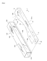
- FIG. 1 is a perspective view of a roll storage apparatus A in which a flap cover 1 is installed on a roll storage case 100.
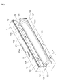
- FIG. 2 is a perspective view showing that the flap cover 1 has not been installed in the roll storage case 100 yet.
- the flap cover 1 is removably installed on a flap 102 of the roll storage case 100, for example, as shown in FIG. 1 and FIG. 2 .
- the flap cover 1 has an upper plate 10 shaped generally like a rectangular parallelepiped and covering an upper surface portion 103 of the flap 102, a front plate 11 shaped generally like a rectangular parallelepiped and covering a front surface portion 104 of the flap 102, and a pair of square side plates 12 covering respective opposite side surface portions 105 of the flap 102.
- a rear surface side and a bottom surface side of the flap cover 1 are open.
- a circular arc-like cutout 20 may be formed in the longitudinal (lateral direction X) center of a rear end side 10a of the upper plate 10.
- the front plate 11 is formed to be shorter than the front surface portion 104 of the flap 102 in the vertical direction so as to expose a cutting edge 106 of the flap 102.
- a hooking portion for a user's finger is preferably formed in the center of the front plate 11 in the lateral direction X.
- the hooking portion may be, for example, a projecting portion 21 projecting forward and extending in the lateral direction X.
- the hooking portion may further include a recess portion formed therein and in which the user's finger can be placed.
- the projecting portion 21 is shaped to appear like a wave in a plan view and includes a recess 21 a formed in the center of the projecting portion 21 in the lateral direction X.
- the projecting portion 21 may be formed exclusively in a central portion of the front plate 1 or all over the front plate 11 in the lateral direction X.
- the projecting portion 21 preferably has a projection length of, for example, 20 mm or less.
- the projecting portion 21 may appear to have another shape in a plan view such as a circular arc or a rectangle.
- the wave shape is more preferable because the user's finger can be more appropriately hooked on the wave-like projecting portion 21 to easily apply a force to the flap cover, thus allowing the flap 102 to be smoothly opened and closed.
- inward projecting locking portion 22 is formed on a lower end portion of each of the side plates 12.
- the locking portion 22 projects inward from the lower end portion of the side plate 12 and at right angle to the side plate 12.
- the locking portion 22 includes a horizontal upper surface 22a formed as an upper surface thereof.
- the side plate 12 and the locking portion 22 form an L shape.
- the flap cover 1 When the flap cover 1 is installed on the flap 102, the side surface portion 105 of the flap 102 is placed on the horizontal upper surface 22a as shown in FIG. 4 .
- the locking portion 22 is locked on the lower end surface of the side surface portion 105 of the flap 102.
- the locking portion 22 is hooked on the lower end surface of the side surface portion 105 of the flap 102 to lift the side surface portion 105 to open the flap 102.
- the flap cover 1 is formed of a material having a higher strength than a material for the roll storage case 100.
- the flap cover 1 is formed using a material having an appropriate rigidity and an appropriate elasticity, for example, plastics or aluminum.
- plastics include ABS, polystyrene, PC, an acrylic resin, polypropylene, and a polyethylene resin.
- ABS, polystyrene, PC, an acrylic resin, and the like are more preferable which are very rigid resins.
- a well-known antimicrobial agent may be added to these resins.
- the flap cover 1 may be designed by coloring or printing or may be transparent. If the flap cover 1 is transparent, characters or pictures on the surface of the roll storage case 100 are visible even when the flap cover 1 is installed.
- the flap cover 1 is placed in front of the roll storage case 100.
- the flap cover 1 is installed on the flap 102 by being inserted over the flap 102 from a front side so that the locking portion 22 of the flap cover 1 is placed under the lower end surface of the side surface portion 105 of the flap 102.
- the upper surface portion 103, the front surface portion 104, and the side surface portions 105 of the flap 102 are covered by the flap cover 1.
- the flap 102 is locked on the flap cover 1 by the locking portion 22.
- the flap cover 1 is gripped so that the user's palm is positioned near the cutout 20.
- the flap cover 1 is rotationally moved to open the flap 102.
- a predetermined amount of film 108 in the roll storage case 100 is drawn out.
- the flap cover 1 closes the flap 102, and the film 108 is tensed.
- the film 108 kept under tension, is cut into a predetermined length with the cutting edge 106.
- the flap cover 1 is removed from the flap 102. At this time, the flap cover 1 is removed by being pulled out forward from the flap 102 in a direction opposite to the direction in which the flap cover 1 is moved during installation so that locking portion 22 of the flap cover 1 slips out from under the lower end surface of the side surface portion 105 of the flap 102. Then, the flap cover 1 is attached to the flap 102 of a next roll storage case 100 containing new film 108.
- the flap 102 is held by the flap cover 1 by locking the locking portion 22 of each of the side plates 12 of the flap cover 1 on the lower end surface of the corresponding side surface portion 105 of the flap 102.
- the flap cover 1 is prevented from being pressed against the flap 102 as is the case with the conventional technique, allowing the flap 102 to be more easily opened.
- the flap cover 1 can be prevented from slipping off from the flap 102.
- the front plate 11 includes the projecting portion 21 formed thereon and projecting forward and extending in the lateral direction X, for example, the user's thumb can be hooked on the projecting portion 21 to rotationally move the flap cover 1.
- the flap 102 can be easily opened and closed by a weaker force.
- the projecting portion 21 is recessed in the center thereof, for example, the user's thumb can be easily hooked on the projecting portion 21. Furthermore, the user's thumb is guided to the center of the projecting portion 21, and thus, the flap cover 1 can be rotationally moved with the center of the flap cover 1 held by the user's thumb. Hence, the flap 102 can be easily opened and closed by a weaker force.
- the locking portion 22 has the horizontal upper surface 22a formed along the front-back direction of the side plate 12, the locking portion 22 is suitably locked on the horizontal lower end surface of the side surface portion 105 of the flap 102. Furthermore, the flap cover 1 can be suitably installed on and removed from the flap 102 by sliding the flap cover 1 in the horizontal direction to move the horizontal upper surface 22a of the locking portion 22 to and from under the lower end surface of the side surface portion 105 of the flap 102.
- a cutting edge 30 that cuts the film 108 may be formed on the lower end portion of the front plate 11 as shown in FIG. 6 .
- the front plate 11 is formed to be longer than the lower end portion of the front surface portion 104 of the flap 102 so that the film 108 can be entirely cut in a width direction thereof with the cutting edge 30 of the flap cover 1.
- the flap cover 1 can be used in a simple roll storage case with no cutting edge.
- the cutting edge 30 of the flap cover 1 may be formed by attaching a metal cutting edge to the flap cover 1 or forming recesses and protrusions 30a on a back surface 11a of the lower end portion of the front plate 11 as shown in FIG. 7 and FIG. 8 .
- the recesses and protrusions 30a are linearly and contiguously formed on the lower end portion of the back surface 11a of the front plate 11. In such a case, since the cutting edge 30 is provided on the back surface 11a, the user's finger can be restrained from coming into touch with the cutting edge 30 while the roll storage case is in use. Additionally, since the cutting edge 30 includes the recesses and protrusions 30a, the user's finger can be restrained from being hurt even when coming into touch with the cutting edge 30.
- the cutting edge 30 of the flap cover 1 may be formed exclusively on a part of the lower end portion of the front plate 11 as shown in FIG. 9 .
- the cutting edge 30 enables a start point for cutting of the film 108 to be formed so that the film can be cut by propagation of a tear.
- the film 108 can be cut by a weaker force.
- the film 108 is prevented from being notched at a cut end surface thereof. Consequently, the film 108 can be prevented from being longitudinally torn.
- the cutting edge 30 when the cutting edge 30 is formed on a part of the lower end portion of the flap cover 1, if, for example, the edge of the lower end portion is linear or arched in shape (the edge protrudes upward) the cutting edge 30 may be formed exclusively at opposite ends of the lower end portion. If the edge of the lower end portion is V shaped (the edge protrudes downward), the cutting edge may be formed exclusively at a tip portion of the center of the V shape.
- the front plate 11 includes an edge cover 40 that covers the cutting edge 106 of the flap 102 as shown in FIG. 10 .
- the edge cover 40 is formed like, for example, a flexible, pliable sheet and is attached to the vicinity of the lower end portion of the front plate 11.
- the edge cover 40 normally covers the cutting edge 106 and bends according to the angle at which the film 108 is drawn out to be cut. According to this example, the user's finger can be prevented from coming into touch with the cutting edge 106 of the flap 102.
- the edge cover 40 need not necessarily be formed like a sheet but may have another configuration.
- the lower end portion side of the front plate 11 may be extended, and a hinge portion may be provided in the middle of the extended lower end portion side so that the lower end portion is bendable and so that the bent portion can be used as an edge cover.
- the front plate 11 may be formed to be thin enough to be bendable in the vicinity of the lower end portion of the front plate 11 so that the bent portion can be used as an edge cover.
- the lower end portion 23 of each of the side plates 12 may be extended downward from the locking portion 22 to enlarge the side plate 12.
- a step on the side surface side of the roll storage case 100 is eliminated which is formed when the flap cover 1 is installed. Consequently, the roll storage case 100 can be stably placed longitudinally on a flat surface as shown in FIG. 13 .
- the lower end portion 23 of the side plate 12 is located at the same position as that where a bottom surface 110 of the roll storage case 100 is located.
- each of the side plates 12 may be projected from the bottom surface 110 of the roll storage case 100 as shown in FIG. 14 .
- the roll storage case 100 with the flap cover 1 installed thereon can be more stably placed longitudinally on a flat surface.
- the bottom surface 110 of the roll storage case 100 is disposed in such a manner as to hang in the air, hindering heat from being transmitted to the roll 107 inside the roll storage case even when the roll storage case is positioned in a place that becomes hot, for example, on a microwave oven. This enables possible alteration of the film to be suppressed.
- the roll storage case 100 is a plastic wrap storage case, the difficulty with which heat is transmitted to the internal plastic wrap allows a force needed to draw out the plastic wrap to be restrained from being increased by heat.
- the front plate 11 of the flap cover 1 may have a replaceable structure.
- the front plate 11 has, for example, a front plate main body 50 and a front plate replacement portion 51 that is removable from the front plate main body 50, for example, as shown in FIG. 15 .
- the front plate replacement portion 51 is shaped like a square including the lower end portion of the front plate 11.
- the front plate main body 50 is shaped generally like an inverse recess corresponding to the remaining portion of the front plate 11.
- the front plate main body 50 includes such a projecting portion 52 as shown in FIG. 16 which is formed along three sides of an inner edge portion of the front plate main body 50.
- the front plate replacement portion 51 includes a groove portion 54 formed along three sides (an upper surface portion and side surface portions) of an outer edge portion of the front plate replacement portion 51 and fitted over the projecting portion 52.
- the front plate replacement portion 51 can be installed on and removed from the front plate main body 50 by sliding the front plate replacement portion 51 up and down relative to the front plate main body 50 as shown in FIG. 15 .
- the front plate 11 may selectively have a preferable shape or pattern.
- the front plate replacement portion 51 may be exclusively replaced if, for example, the cutting performance of the cutting edge is degraded.
- the front plate 11 may be partly replaceable as in this example or wholly replaceable.
- the front plate replacement portion 51 (front plate main body 50) may have another shape.
- the removal structure need not necessarily be formed like a slide, but any other structure may be used.
- the edge of the lower end portion of the front plate 11 in the above-described embodiment may have a linear shape, an arched shape (an upward protrusion), or V shape (a downward protrusion) so as to be able to deal with any cutting edge shape for linear cutting or central cutting.
- the edge may be formed to conform to the shape of any other cutting edge.
- the locking portion 22 need not necessarily be shaped to project like a horizontal plate as in the case of the above-described embodiment.
- the locking portion 22 may have another shape, for example, the locking portion 22 may project in the horizontal direction and then be curved or bent upward.
- the present invention is not limited to plastic wrap, aluminum foil, and cooking paper but is applicable to a flap cover for a roll storage case storing a roll around which any other film is wound.
- a measurement method and an evaluation method used in an example and a comparative example are as follows.
- a draw-out force is an indicator for a draw-out property, and a smaller value of the draw-out force indicates that the film can be drawn out by a weaker force.
- the draw-out force is measured by the following method. Plastic wrap adjusted to a film width of 30 cm and wound around a paper tube is set in a roll-like jig that can be easily rotated by a very weak force. An end of the film is fixed to a jig with a width of 330 mm which is coupled directly to a load cell of a tensile tester. Then, the maximum value of stress generated when the film is drawn out at a speed of 1,000 mm/min is measured. The measurement is carried out at a constant temperature of 23° C and a constant humidity of 50%. The measurement is carried out ten times, and the resultant average value is adopted. Evaluation criteria are as follows.
- a flap cover 1 with a length Y of 50 mm to the lower end portion 23 of the side plate 12 shown in FIG. 13 was installed on a roll storage case for Saran Wrap (manufactured by Asahi Kasei Home Products Corporation; 30 cm x 20 m).
- the roll storage case was placed on a hot plate with the temperature thereof adjusted to 100°C so that the lower end portion 23 of the side plate 12 contacted the hot plate, whereas the bottom surface 110 of the roll storage case 100 avoided contacting the hot plate.
- the roll storage case was left untreated for 30 minutes.
- the internal wrap was removed from the roll storage case, which was left untreated at a constant temperature of 23°C and a constant humidity of 50% for 30 minutes.
- the draw-out force was measured.
- the draw-out force was 50 cN, and the film was successfully easily drawn out by a weak force of 50 cN.
- a tin cutting edge was removed from a roll storage case for Saran Wrap (manufactured by Asahi Kasei Home Products Corporation; 30 cm x 20 m).
- Saran Wrap manufactured by Asahi Kasei Home Products Corporation; 30 cm x 20 m.
- About 30 cm of the plastic wrap inside the roll storage case was drawn out and cut. Then, the plastic wrap was flawed at a widthwise end thereof, and using the flaw as a start point, a tear of the plastic wrap propagated to the opposite widthwise end of the wrap.
- the plastic wrap was successfully cut by a weak force.
- the present invention is useful in allowing a flap of a roll storage case to be easily opened and closed using a flap cover and in preventing the flap cover from slipping off from the flap of the roll storage case even when the flap is opened and closed many times.
Landscapes
- Engineering & Computer Science (AREA)
- Mechanical Engineering (AREA)
- Details Of Rigid Or Semi-Rigid Containers (AREA)
- Closures For Containers (AREA)
- Cartons (AREA)
Abstract
Description
- The present invention relates to a flap (lid) cover for a roll storage case and a roll storage apparatus which store a roll around which film for food packaging such as plastic wrap, aluminum foil, or cooking paper is wound.
- Film for food packaging such as plastic wrap, aluminum foil, or cooking paper, when in use, is wound around a cylindrical roll, which is stored in a roll storage case formed of paper (see Patent Document 1). As shown in
FIG. 11 , aroll storage case 100 has a rectangular parallelepiped-like case 101 normally shaped generally like a rectangular parallelepiped and including an open upper surface and aflap 102 that covers the open upper surface of thecase 101. Theflap 102 has anupper surface portion 103, afront surface portion 104, andside surface portions 105 located on opposite sides of theflap 102 in a longitudinal direction thereof. Arear end side 103a of theupper surface portion 103 is connected to thecase 101. Theflap 102 can move rotationally using therear end side 103a as an axis to open and close the open upper surface of thecase 101. Acutting edge 106 that cuts film is provided at a lower end portion of thefront surface portion 104. - When film for the
roll storage case 100 is used, theflap 102 is opened, and a necessary amount offilm 108 on aroll 107 is drawn out. Then, theflap 102 is closed, and with tension applied to thefilm 108, thefilm 108 is cut into a desired length using thecutting edge 106 of thefront surface portion 104. - About 5 m to 50 m of
film 108 is wound around theroll 107, and thus, thefilm 108 is cut a number of times before thefilm 108 is used up. Thus, each time thefilm 108 is cut, thefront surface portion 104 orupper surface portion 103 of theflap 102, on which a load is placed, may be deformed. In particular, theroll storage case 100 is often used in a place with much moisture such as a kitchen, and is thus likely to be deformed by absorbing the moisture. When theflap 102 with thecutting edge 106 is deformed, thefilm 108 fails to be properly cut and may be torn. Furthermore, hooking a user's finger on theroll storage case 100 is difficult, and thus, theflap 102 is difficult to open and close. Consequently, thefilm 108 may be drawn out with theflap 102 imperfectly opened and hence come into contact with thecutting edge 106, causing thefilm 108 to be torn. In another case, thefilm 108 may be cut with theflap 102 imperfectly closed and hence wound back around theroll 107. Then, theroll storage case 100 may be difficult to use. - Thus, in order to prevent the flap of the roll storage case from being deformed, a flap reinforcing cover that covers the flap has been proposed (see Patent Document 2). The flap reinforcing cover is attached to a surface of the flap of the roll storage case, and is held and rotationally moved to open and close the flap. When the flap of the roll storage case is opened or closed, the flap reinforcing cover needs to hold the flap. The holding is achieved by forming a tongue-like elastic body on a side surface of the flap reinforcing cover and pressing the tongue-like elastic body against the side surface portion of the flap, which is located inside the tongue-like elastic body.
- [Patent Document 1]
JP-A-2003-160141 - [Patent Document 2]
JP-A-2004-352356 - However, when the tongue-like elastic body of the flap reinforcing cover is pressed and held against the side surface portion of the flap as described above, the side surface portion of the flap is also pressed against the side surface portion on the inside of the case. The side surface portion of the flap is sandwiched between the tongue-like elastic body and the side surface portion of the case, making the flap difficult to open. Furthermore, opening and closing the flap many times gradually reduces the pressing force of the tongue-like elastic body. The flap reinforcing cover may slip off from the flap.
- In view of these problems, it is an object of the present invention to provide a flap cover for a roll storage case and a roll storage apparatus which allow the flap of the roll storage case to be easily opened and closed and which can prevent the flap cover from slipping off from the flap of the roll storage case even when the flap is opened and closed many times.
- To accomplish the object, the present invention provides a flap cover removably installed on a flap of a roll storage case storing a roll around which film is wound, the flap cover including an upper plate covering an upper surface portion of the flap, a front plate covering a front surface portion of the flap, and a pair of side plates covering opposite side surface portions of the flap, wherein each of the side plates is provided with a locking portion which projects inward from the side plate and which is able to be locked on a lower end surface of the side surface portion of the flap.
- According to the present invention, the flap is held by the flap cover by locking the locking portion of each of the side plates of the flap cover on the lower end surface of the corresponding side surface portion of the flap. This prevents the side surface portion of the flap from being pressed inward as in the case of the conventional technique, increasing the easiness with which the flap is opened. Furthermore, the flap cover can be prevented from slipping off from the flap even when the flap is opened and closed many times.
- The front plate may include a projecting portion projecting forward and extending in a lateral direction. In such a case, for example, a user's thumb can be hooked on the projecting portion to rotationally move the flap cover. Thus, the flap can be easily opened and closed by a reduced force.
- The projecting portion may be recessed in a center thereof. In such a case, for example, the user's thumb can be easily hooked on the projecting portion to more easily open and close the flap.
- The locking portion may have a horizontal upper surface formed along a front-back direction of the side plate. In such a case, the locking portion is suitably locked on the horizontal lower end surface of the side surface portion of the flap.
- The front plate may include a cutting edge formed on a lower end portion of the front plate to cut film. In such a case, the flap cover can be used for a simple roll storage case with no cutting edge attached thereto.
- The cutting edge may be formed on a part of the lower end portion of the front plate. In such a case, the cutting edge can form in film just a scratch that serves as a start point of cutting. This makes it possible for the film to be cut by extending the scratch. In such a case, a cut end surface of the film is prevented from being notched, restraining the film from being torn in a longitudinal direction thereof.
- The cutting edge may be formed by forming recesses and protrusions on a back surface of the lower end portion of the front plate. In such a case, for example, the user's finger can be restrained from coming into touch with the cutting edge while the roll storage case is in use. Furthermore, even upon coming into touch with the cutting edge, the user's finger is prevented from being hurt.
- The front plate may include an edge cover covering the cutting edge of the flap. In such a case, for example, the user's finger can be prevented from coming into touch with the cutting edge of the flap while the roll storage case is in use.
- Each of the side plates may extend downward from the locking portion. In such a case, the roll storage case can be stably placed longitudinally on a flat surface (placed with one of the side plates of the roll storage case on a flat surface). Furthermore, each of the side plates may extend downward from a bottom surface of the roll storage case. In such a case, the roll storage case can be more stably placed longitudinally on a flat surface. Additionally, when the roll storage case is placed transversely on a flat surface (placed with an upper plate of the roll storage case facing upward), the bottom surface of the roll storage case is disposed in such a manner as to hang in the air, hindering heat from being transmitted to the film inside the roll storage case even when the roll storage case is positioned in a place that becomes hot, for example, on a microwave oven. This enables possible alteration of the film to be suppressed.
- The front plate may have a replaceable structure. In such a case, the front plate may selectively have a favorable shape or pattern. Furthermore, if the front plate has a function to cut film, the front plate portion can be exclusively replaced when the cutting function is degraded.
- Another aspect of the present invention provides a roll storage apparatus having a roll storage case and a flap cover for the roll storage case which is able to be attached to the roll storage case.
- The aspects of the present invention allow the flap of the roll storage case to be easily opened and closed and can prevent the flap cover from slipping off from the flap of the roll storage case even when the flap is opened and closed many times.
-
-
FIG. 1 is a perspective view of a flap cover according to an embodiment installed in a roll storage case; -
FIG. 2 is a perspective view showing that the flap cover has not been installed in the roll storage case yet; -
FIG. 3 is a rear view of the flap cover; -
FIG. 4 is a vertical cross-sectional view of the periphery of a side plate of the flap cover; -
FIG. 5 is a perspective view showing that a flap of a roll storage case is opened using the flap cover; -
FIG. 6 is a front view showing a flap cover with a cutting edge; -
FIG. 7 is a front view showing a flap cover with a cutting edge on a back surface of a front plate; -
FIG. 8 is a vertical cross-sectional view showing recesses and protrusions of the cutting edge on the front plate of the flap cover; -
FIG. 9 is a front view of a flap cover with a cutting edge on a part of a lower end portion of the front plate; -
FIG. 10 is a perspective view showing a flap cover with an edge cover; -
FIG. 11 is a perspective view of a roll storage case; -
FIG. 12 is a front view of a flap cover installed on the roll storage case and having a side plate extending downward from a locking portion; -
FIG. 13 is a diagram illustrating that the roll storage case on which the flap cover with the extended side plates is installed is placed longitudinally on a flat surface; -
FIG. 14 is a front view of a flap cover installed on the roll storage case and having side plates extending from a bottom surface of the roll storage case; -
FIG. 15 is a front view showing a flap cover configured to have a replaceable front plate; and -
FIG. 16 is a cross-sectional view showing a mating structure for a front plate main body of the front plate and a front plate replacement portion. - A preferred embodiment of the present invention will be described below with reference to the drawings.
FIG. 1 is a perspective view of a roll storage apparatus A in which aflap cover 1 is installed on aroll storage case 100.FIG. 2 is a perspective view showing that theflap cover 1 has not been installed in theroll storage case 100 yet. - The
flap cover 1 is removably installed on aflap 102 of theroll storage case 100, for example, as shown inFIG. 1 andFIG. 2 . Theflap cover 1 has anupper plate 10 shaped generally like a rectangular parallelepiped and covering anupper surface portion 103 of theflap 102, afront plate 11 shaped generally like a rectangular parallelepiped and covering afront surface portion 104 of theflap 102, and a pair ofsquare side plates 12 covering respective oppositeside surface portions 105 of theflap 102. As shown inFIG. 3 , a rear surface side and a bottom surface side of theflap cover 1 are open. - As shown in
FIG. 1 andFIG. 2 , a circular arc-like cutout 20 may be formed in the longitudinal (lateral direction X) center of arear end side 10a of theupper plate 10. Thefront plate 11 is formed to be shorter than thefront surface portion 104 of theflap 102 in the vertical direction so as to expose acutting edge 106 of theflap 102. A hooking portion for a user's finger is preferably formed in the center of thefront plate 11 in the lateral direction X. The hooking portion may be, for example, a projectingportion 21 projecting forward and extending in the lateral direction X. The hooking portion may further include a recess portion formed therein and in which the user's finger can be placed. For example, the projectingportion 21 is shaped to appear like a wave in a plan view and includes arecess 21 a formed in the center of the projectingportion 21 in the lateral direction X. The projectingportion 21 may be formed exclusively in a central portion of thefront plate 1 or all over thefront plate 11 in the lateral direction X. The projectingportion 21 preferably has a projection length of, for example, 20 mm or less. Furthermore, the projectingportion 21 may appear to have another shape in a plan view such as a circular arc or a rectangle. However, the wave shape is more preferable because the user's finger can be more appropriately hooked on the wave-like projectingportion 21 to easily apply a force to the flap cover, thus allowing theflap 102 to be smoothly opened and closed. - As shown in
FIG. 3 , inward projecting lockingportion 22 is formed on a lower end portion of each of theside plates 12. The lockingportion 22, for example, projects inward from the lower end portion of theside plate 12 and at right angle to theside plate 12. The lockingportion 22 includes a horizontalupper surface 22a formed as an upper surface thereof. Theside plate 12 and the lockingportion 22 form an L shape. When theflap cover 1 is installed on theflap 102, theside surface portion 105 of theflap 102 is placed on the horizontalupper surface 22a as shown inFIG. 4 . Thus, the lockingportion 22 is locked on the lower end surface of theside surface portion 105 of theflap 102. When theflap cover 1 is rotationally moved, the lockingportion 22 is hooked on the lower end surface of theside surface portion 105 of theflap 102 to lift theside surface portion 105 to open theflap 102. - The
flap cover 1 is formed of a material having a higher strength than a material for theroll storage case 100. Theflap cover 1 is formed using a material having an appropriate rigidity and an appropriate elasticity, for example, plastics or aluminum. Examples of the plastics include ABS, polystyrene, PC, an acrylic resin, polypropylene, and a polyethylene resin. Among these plastics, ABS, polystyrene, PC, an acrylic resin, and the like are more preferable which are very rigid resins. A well-known antimicrobial agent may be added to these resins. Furthermore, theflap cover 1 may be designed by coloring or printing or may be transparent. If theflap cover 1 is transparent, characters or pictures on the surface of theroll storage case 100 are visible even when theflap cover 1 is installed. - Now, an example of a usage of the
flap cover 1 configured as described above will be described. First, as shown inFIG. 2 , theflap cover 1 is placed in front of theroll storage case 100. Theflap cover 1 is installed on theflap 102 by being inserted over theflap 102 from a front side so that the lockingportion 22 of theflap cover 1 is placed under the lower end surface of theside surface portion 105 of theflap 102. Thus, as shown inFIG. 1 , theupper surface portion 103, thefront surface portion 104, and theside surface portions 105 of theflap 102 are covered by theflap cover 1. Furthermore, theflap 102 is locked on theflap cover 1 by the lockingportion 22. - Then, the user's thumb is hooked on the projecting
portion 21, and theflap cover 1 is gripped so that the user's palm is positioned near thecutout 20. As shown inFIG. 5 , theflap cover 1 is rotationally moved to open theflap 102. Subsequently, a predetermined amount offilm 108 in theroll storage case 100 is drawn out. Then, theflap cover 1 closes theflap 102, and thefilm 108 is tensed. Thefilm 108, kept under tension, is cut into a predetermined length with thecutting edge 106. - When the
film 108 is cut a number of times and all of thefilm 108 on aroll 107 is used up, theflap cover 1 is removed from theflap 102. At this time, theflap cover 1 is removed by being pulled out forward from theflap 102 in a direction opposite to the direction in which theflap cover 1 is moved during installation so that lockingportion 22 of theflap cover 1 slips out from under the lower end surface of theside surface portion 105 of theflap 102. Then, theflap cover 1 is attached to theflap 102 of a nextroll storage case 100 containingnew film 108. - According to the above-described embodiment, the
flap 102 is held by theflap cover 1 by locking the lockingportion 22 of each of theside plates 12 of theflap cover 1 on the lower end surface of the correspondingside surface portion 105 of theflap 102. Thus, theflap cover 1 is prevented from being pressed against theflap 102 as is the case with the conventional technique, allowing theflap 102 to be more easily opened. Furthermore, even when theflap 102 is opened and closed a number of times, theflap cover 1 can be prevented from slipping off from theflap 102. - Since the
front plate 11 includes the projectingportion 21 formed thereon and projecting forward and extending in the lateral direction X, for example, the user's thumb can be hooked on the projectingportion 21 to rotationally move theflap cover 1. Thus, theflap 102 can be easily opened and closed by a weaker force. - Since the projecting
portion 21 is recessed in the center thereof, for example, the user's thumb can be easily hooked on the projectingportion 21. Furthermore, the user's thumb is guided to the center of the projectingportion 21, and thus, theflap cover 1 can be rotationally moved with the center of theflap cover 1 held by the user's thumb. Hence, theflap 102 can be easily opened and closed by a weaker force. - Since the locking
portion 22 has the horizontalupper surface 22a formed along the front-back direction of theside plate 12, the lockingportion 22 is suitably locked on the horizontal lower end surface of theside surface portion 105 of theflap 102. Furthermore, theflap cover 1 can be suitably installed on and removed from theflap 102 by sliding theflap cover 1 in the horizontal direction to move the horizontalupper surface 22a of the lockingportion 22 to and from under the lower end surface of theside surface portion 105 of theflap 102. - In the
flap cover 1 in the above-described embodiment, acutting edge 30 that cuts thefilm 108 may be formed on the lower end portion of thefront plate 11 as shown inFIG. 6 . In such a case, thefront plate 11 is formed to be longer than the lower end portion of thefront surface portion 104 of theflap 102 so that thefilm 108 can be entirely cut in a width direction thereof with thecutting edge 30 of theflap cover 1. According to this example, theflap cover 1 can be used in a simple roll storage case with no cutting edge. - Furthermore, the
cutting edge 30 of theflap cover 1 may be formed by attaching a metal cutting edge to theflap cover 1 or forming recesses andprotrusions 30a on aback surface 11a of the lower end portion of thefront plate 11 as shown inFIG. 7 andFIG. 8 . The recesses andprotrusions 30a are linearly and contiguously formed on the lower end portion of theback surface 11a of thefront plate 11. In such a case, since thecutting edge 30 is provided on theback surface 11a, the user's finger can be restrained from coming into touch with thecutting edge 30 while the roll storage case is in use. Additionally, since thecutting edge 30 includes the recesses andprotrusions 30a, the user's finger can be restrained from being hurt even when coming into touch with thecutting edge 30. - In this case, the
cutting edge 30 of theflap cover 1 may be formed exclusively on a part of the lower end portion of thefront plate 11 as shown inFIG. 9 . In such a case, thecutting edge 30 enables a start point for cutting of thefilm 108 to be formed so that the film can be cut by propagation of a tear. Thus, thefilm 108 can be cut by a weaker force. Furthermore, since thefilm 108 is cut by the propagation, thefilm 108 is prevented from being notched at a cut end surface thereof. Consequently, thefilm 108 can be prevented from being longitudinally torn. Additionally, when thecutting edge 30 is formed on a part of the lower end portion of theflap cover 1, if, for example, the edge of the lower end portion is linear or arched in shape (the edge protrudes upward) thecutting edge 30 may be formed exclusively at opposite ends of the lower end portion. If the edge of the lower end portion is V shaped (the edge protrudes downward), the cutting edge may be formed exclusively at a tip portion of the center of the V shape. - In the
flap cover 1 in the above-described embodiment, thefront plate 11 includes anedge cover 40 that covers thecutting edge 106 of theflap 102 as shown inFIG. 10 . Theedge cover 40 is formed like, for example, a flexible, pliable sheet and is attached to the vicinity of the lower end portion of thefront plate 11. Theedge cover 40 normally covers thecutting edge 106 and bends according to the angle at which thefilm 108 is drawn out to be cut. According to this example, the user's finger can be prevented from coming into touch with thecutting edge 106 of theflap 102. Theedge cover 40 need not necessarily be formed like a sheet but may have another configuration. For example, the lower end portion side of thefront plate 11 may be extended, and a hinge portion may be provided in the middle of the extended lower end portion side so that the lower end portion is bendable and so that the bent portion can be used as an edge cover. Alternatively, thefront plate 11 may be formed to be thin enough to be bendable in the vicinity of the lower end portion of thefront plate 11 so that the bent portion can be used as an edge cover. - Furthermore, as shown in
FIG. 12 , thelower end portion 23 of each of theside plates 12 may be extended downward from the lockingportion 22 to enlarge theside plate 12. Thus, a step on the side surface side of theroll storage case 100 is eliminated which is formed when theflap cover 1 is installed. Consequently, theroll storage case 100 can be stably placed longitudinally on a flat surface as shown inFIG. 13 . This prevents the roll storage case from occupying a large space in the kitchen and allows the roll storage case to be stored in a narrow place. In this example, thelower end portion 23 of theside plate 12 is located at the same position as that where abottom surface 110 of theroll storage case 100 is located. - Alternatively, the
lower end portion 23 of each of theside plates 12 may be projected from thebottom surface 110 of theroll storage case 100 as shown inFIG. 14 . In such a case, theroll storage case 100 with theflap cover 1 installed thereon can be more stably placed longitudinally on a flat surface. Additionally, when theroll storage case 100 is placed transversely on a flat surface, thebottom surface 110 of theroll storage case 100 is disposed in such a manner as to hang in the air, hindering heat from being transmitted to theroll 107 inside the roll storage case even when the roll storage case is positioned in a place that becomes hot, for example, on a microwave oven. This enables possible alteration of the film to be suppressed. In particular, when theroll storage case 100 is a plastic wrap storage case, the difficulty with which heat is transmitted to the internal plastic wrap allows a force needed to draw out the plastic wrap to be restrained from being increased by heat. - Furthermore, the
front plate 11 of theflap cover 1 may have a replaceable structure. In such a case, thefront plate 11 has, for example, a front platemain body 50 and a frontplate replacement portion 51 that is removable from the front platemain body 50, for example, as shown inFIG. 15 . The frontplate replacement portion 51 is shaped like a square including the lower end portion of thefront plate 11. The front platemain body 50 is shaped generally like an inverse recess corresponding to the remaining portion of thefront plate 11. The front platemain body 50 includes such a projectingportion 52 as shown inFIG. 16 which is formed along three sides of an inner edge portion of the front platemain body 50. The frontplate replacement portion 51 includes a groove portion 54 formed along three sides (an upper surface portion and side surface portions) of an outer edge portion of the frontplate replacement portion 51 and fitted over the projectingportion 52. Hence, the frontplate replacement portion 51 can be installed on and removed from the front platemain body 50 by sliding the frontplate replacement portion 51 up and down relative to the front platemain body 50 as shown inFIG. 15 . In such a case, thefront plate 11 may selectively have a preferable shape or pattern. Additionally, when the frontplate replacement portion 51 includes thecutting edge 30 at the lower end thereof as shown inFIG. 15 , the frontplate replacement portion 51 may be exclusively replaced if, for example, the cutting performance of the cutting edge is degraded. Thefront plate 11 may be partly replaceable as in this example or wholly replaceable. Alternatively, the front plate replacement portion 51 (front plate main body 50) may have another shape. In addition, the removal structure need not necessarily be formed like a slide, but any other structure may be used. - The preferred embodiment of the present invention has been described with reference to the attached drawings. However, the present invention is not limited to such an example. Obviously, those skilled in the art may arrive at various changes or modifications without departing from the scope of the concepts set forth in the claims. It is appreciated that such changes or modifications belong to the technical scope of the present invention.
- For example, the edge of the lower end portion of the
front plate 11 in the above-described embodiment may have a linear shape, an arched shape (an upward protrusion), or V shape (a downward protrusion) so as to be able to deal with any cutting edge shape for linear cutting or central cutting. The edge may be formed to conform to the shape of any other cutting edge. - Furthermore, the locking
portion 22 need not necessarily be shaped to project like a horizontal plate as in the case of the above-described embodiment. The lockingportion 22 may have another shape, for example, the lockingportion 22 may project in the horizontal direction and then be curved or bent upward. The present invention is not limited to plastic wrap, aluminum foil, and cooking paper but is applicable to a flap cover for a roll storage case storing a roll around which any other film is wound. - A measurement method and an evaluation method used in an example and a comparative example are as follows.
- A draw-out force is an indicator for a draw-out property, and a smaller value of the draw-out force indicates that the film can be drawn out by a weaker force. The draw-out force is measured by the following method. Plastic wrap adjusted to a film width of 30 cm and wound around a paper tube is set in a roll-like jig that can be easily rotated by a very weak force. An end of the film is fixed to a jig with a width of 330 mm which is coupled directly to a load cell of a tensile tester. Then, the maximum value of stress generated when the film is drawn out at a speed of 1,000 mm/min is measured. The measurement is carried out at a constant temperature of 23° C and a constant humidity of 50%. The measurement is carried out ten times, and the resultant average value is adopted. Evaluation criteria are as follows.
- o (appropriate): less than 100 cN
- X (inappropriate): 100 cN or more
- A
flap cover 1 with a length Y of 50 mm to thelower end portion 23 of theside plate 12 shown inFIG. 13 was installed on a roll storage case for Saran Wrap (manufactured by Asahi Kasei Home Products Corporation; 30 cm x 20 m). The roll storage case was placed on a hot plate with the temperature thereof adjusted to 100°C so that thelower end portion 23 of theside plate 12 contacted the hot plate, whereas thebottom surface 110 of theroll storage case 100 avoided contacting the hot plate. The roll storage case was left untreated for 30 minutes. Then, the internal wrap was removed from the roll storage case, which was left untreated at a constant temperature of 23°C and a constant humidity of 50% for 30 minutes. Then, the draw-out force was measured. The draw-out force was 50 cN, and the film was successfully easily drawn out by a weak force of 50 cN. - A tin cutting edge was removed from a roll storage case for Saran Wrap (manufactured by Asahi Kasei Home Products Corporation; 30 cm x 20 m). Such a flap cover with cutting edges at respective opposite ends of a back surface of a front plate as shown in
FIG. 9 was installed on the roll storage case. About 30 cm of the plastic wrap inside the roll storage case was drawn out and cut. Then, the plastic wrap was flawed at a widthwise end thereof, and using the flaw as a start point, a tear of the plastic wrap propagated to the opposite widthwise end of the wrap. Thus, the plastic wrap was successfully cut by a weak force. - The present invention is useful in allowing a flap of a roll storage case to be easily opened and closed using a flap cover and in preventing the flap cover from slipping off from the flap of the roll storage case even when the flap is opened and closed many times.
-
- 1
- Flap cover
- 10
- Upper plate
- 11
- Front plate
- 12
- Side plate
- 21
- Projecting portion
- 22
- Locking portion
- 100
- Roll storage case
- 101
- Case
- 102
- Flap
- 103
- Upper surface portion
- 104
- Front surface portion
- 105
- Side surface portion
- 106
- Cutting edge
- 107
- Roll
- 108
- Film
- X
- Lateral direction
- A
- Roll storage apparatus
Claims (12)
- A flap cover for a roll storage case storing a roll around which film is wound, the flap cover being removably installed on a flap of the roll storage case,
the flap cover comprising:an upper plate covering an upper surface portion of the flap;a front plate covering a front surface portion of the flap; anda pair of side plates covering opposite side surface portions of the flap,wherein each of the side plates is provided with a locking portion which projects inward from the side plate and which is able to be locked on a lower end surface of the side surface portion of the flap. - The flap cover for a roll storage case according to claim 1, wherein the front plate comprises a projecting portion projecting forward and extending in a lateral direction.
- The flap cover for a roll storage case according to claim 2, wherein the projecting portion is recessed in a center thereof.
- The flap cover for a roll storage case according to any of claims 1 to 3, wherein the locking portion comprises a horizontal upper surface formed along a front-back direction of the side plate.
- The flap cover for a roll storage case according to any of claims 1 to 4, wherein the front plate comprises a cutting edge formed on a lower end portion of the front plate to cut film.
- The flap cover for a roll storage case according to claim 5, wherein the cutting edge is formed on a part of the lower end portion of the front plate.
- The flap cover for a roll storage case according to claim 5 or claim 6, wherein the cutting edge is formed by forming recesses and protrusions on a back surface of the lower end portion of the front plate.
- The flap cover for a roll storage case according to any of claims 1 to 7, wherein the front plate comprises an edge cover covering the cutting edge of the flap.
- The flap cover for a roll storage case according to any of claims 1 to 8, wherein each of the side plates extends downward from the locking portion.
- The flap cover for a roll storage case according to claim 9, wherein each of the side plates extends downward from a bottom surface of the roll storage case.
- The flap cover for a roll storage case according to any of claims 1 to 10, wherein the front plate has a replaceable structure.
- A roll storage apparatus comprising:a roll storage case; andthe flap cover for the roll storage case according to any of claims 1 to 11 which is able to be attached to the roll storage case.
Applications Claiming Priority (1)
| Application Number | Priority Date | Filing Date | Title |
|---|---|---|---|
| PCT/JP2011/071012 WO2013038522A1 (en) | 2011-09-14 | 2011-09-14 | Lid cover for rolled cylinder storage box and rolled cylinder storage device |
Publications (2)
| Publication Number | Publication Date |
|---|---|
| EP2757048A1 true EP2757048A1 (en) | 2014-07-23 |
| EP2757048A4 EP2757048A4 (en) | 2015-07-15 |
Family
ID=47882781
Family Applications (1)
| Application Number | Title | Priority Date | Filing Date |
|---|---|---|---|
| EP11872332.9A Withdrawn EP2757048A4 (en) | 2011-09-14 | 2011-09-14 | COVER COVER FOR ROLLER CYLINDER STORAGE BOX AND ROLLER CYLINDER STORAGE DEVICE |
Country Status (8)
| Country | Link |
|---|---|
| US (1) | US20140263527A1 (en) |
| EP (1) | EP2757048A4 (en) |
| JP (1) | JP5712297B2 (en) |
| KR (1) | KR101507264B1 (en) |
| CN (1) | CN103732505B (en) |
| IN (1) | IN2014CN01722A (en) |
| SG (1) | SG11201400231VA (en) |
| WO (1) | WO2013038522A1 (en) |
Families Citing this family (12)
| Publication number | Priority date | Publication date | Assignee | Title |
|---|---|---|---|---|
| US9221646B1 (en) * | 2013-02-11 | 2015-12-29 | Tony Simeon Amara | Combined aluminum and plastic food wrap and associated use thereof |
| JP6064302B2 (en) * | 2013-03-25 | 2017-01-25 | 大日本印刷株式会社 | Carton for wrap film |
| JP6064303B2 (en) * | 2013-03-25 | 2017-01-25 | 大日本印刷株式会社 | Carton for wrap film |
| JP6132138B2 (en) * | 2013-03-25 | 2017-05-24 | 大日本印刷株式会社 | Carton for wrap film |
| DE202014100610U1 (en) * | 2014-02-12 | 2014-03-11 | Cofresco Frischhalteprodukte Gmbh & Co. Kg | packaging |
| CN104386525A (en) * | 2014-10-31 | 2015-03-04 | 四川汇利实业有限公司 | Household foil packing box capable of realizing counting function and cutting function |
| JP6695734B2 (en) * | 2015-12-15 | 2020-05-20 | 旭化成株式会社 | Infection prevention film |
| WO2018012476A1 (en) * | 2016-07-12 | 2018-01-18 | 旭化成株式会社 | Box for housing pressure-sensitive - adhesive film therein, device including pressure-sensitive-adhesive film housed therein, and infection-preventing film |
| JP6684193B2 (en) * | 2016-10-03 | 2020-04-22 | 旭化成株式会社 | Infection prevention film |
| USD861477S1 (en) * | 2017-10-02 | 2019-10-01 | Reynolds Consumer Products LLC | Container |
| USD873129S1 (en) * | 2017-12-07 | 2020-01-21 | The Procter & Gamble Company | Container |
| JP6932286B2 (en) * | 2019-03-19 | 2021-09-08 | 株式会社クレハ | Cutting blades and packaging containers |
Family Cites Families (23)
| Publication number | Priority date | Publication date | Assignee | Title |
|---|---|---|---|---|
| US1991812A (en) * | 1933-09-28 | 1935-02-19 | Marcalus Nicholas | Dispensing box |
| US2314849A (en) * | 1940-12-16 | 1943-03-23 | Marathon Paper Mills Co | Dispensing carton |
| US2334757A (en) * | 1941-04-22 | 1943-11-23 | Wyatt H Ensminger | Sheet paper dispenser |
| US2474076A (en) * | 1946-12-17 | 1949-06-21 | Claude H Thompson | Dispensing container |
| US2893616A (en) * | 1957-10-25 | 1959-07-07 | Prec Metal Workers | Web dispenser |
| US3173590A (en) * | 1963-03-29 | 1965-03-16 | Georgia Pacific Corp | Dispenser for rolled material |
| US4196647A (en) * | 1978-08-15 | 1980-04-08 | Reynolds Metals Company | Carton for dispensing and cutting sheet material |
| US4307828A (en) * | 1980-06-19 | 1981-12-29 | The Dow Chemical Company | Dispensing carton |
| IT210047Z2 (en) * | 1987-03-19 | 1988-11-14 | Manuliplast Spa | CONTAINER PARTICULARLY DESIGNED FOR FILM, FOR THE PRESERVATION OF FOOD PRODUCTS. |
| US4899918A (en) * | 1987-04-20 | 1990-02-13 | Kurheha Chemical Industry Company Limited | Dispensing carton for a roll film |
| US4844310A (en) * | 1987-05-14 | 1989-07-04 | Geleziunas Rimas J | Dispenser for a roll of sheet material |
| US5511663A (en) * | 1993-12-15 | 1996-04-30 | Kureha Kagaku Kogyo Kabushiki Kaisha | Packaging case having improved sidewall structure |
| US5620128A (en) * | 1995-02-17 | 1997-04-15 | Robert K. Dingman | Dispenser for rolled sheet material |
| US5630563A (en) * | 1995-06-05 | 1997-05-20 | Reynolds Metals Company | Apparatus for dispensing a controlled length of sheet material from a roll |
| JP2000033951A (en) * | 1998-07-21 | 2000-02-02 | Emuka:Kk | Wrap film for food packaging and cutter for aluminum foil |
| JP3707389B2 (en) * | 1999-05-14 | 2005-10-19 | 義一 高山 | Wrap film feeder |
| US6405913B1 (en) * | 1999-12-22 | 2002-06-18 | Green Bay Packaging, Inc. | Paperboard dispenser carton with plastic cutting blade |
| JP2003160141A (en) | 2001-11-26 | 2003-06-03 | Asahi Sekkei Kogyo:Kk | Box structure of food wrap film wrapped with a blade deformation holding plate. |
| US20030178462A1 (en) * | 2002-03-19 | 2003-09-25 | Johnson Huang | Film wrapper cutting device |
| JP2004352356A (en) * | 2003-05-27 | 2004-12-16 | Masao Kosuge | Lid body reinforcement cover for paper carton encasing wrap film |
| CN2717901Y (en) * | 2004-08-09 | 2005-08-17 | 毛秀清 | Box for dispensing fresh-keeping membrane |
| JP4333739B2 (en) * | 2006-12-16 | 2009-09-16 | 真由美 木下 | Roll storage case cover |
| JP3158113U (en) * | 2009-12-02 | 2010-03-18 | 肇 楠本 | Removable wrap film paper box reinforcement equipment |
-
2011
- 2011-09-14 JP JP2013533397A patent/JP5712297B2/en active Active
- 2011-09-14 EP EP11872332.9A patent/EP2757048A4/en not_active Withdrawn
- 2011-09-14 WO PCT/JP2011/071012 patent/WO2013038522A1/en not_active Ceased
- 2011-09-14 US US14/343,986 patent/US20140263527A1/en not_active Abandoned
- 2011-09-14 KR KR1020137031625A patent/KR101507264B1/en active Active
- 2011-09-14 CN CN201180072753.8A patent/CN103732505B/en active Active
- 2011-09-14 SG SG11201400231VA patent/SG11201400231VA/en unknown
- 2011-09-14 IN IN1722CHN2014 patent/IN2014CN01722A/en unknown
Also Published As
| Publication number | Publication date |
|---|---|
| EP2757048A4 (en) | 2015-07-15 |
| KR20140004237A (en) | 2014-01-10 |
| CN103732505A (en) | 2014-04-16 |
| SG11201400231VA (en) | 2014-08-28 |
| HK1195538A1 (en) | 2014-11-14 |
| CN103732505B (en) | 2015-04-29 |
| US20140263527A1 (en) | 2014-09-18 |
| JPWO2013038522A1 (en) | 2015-03-23 |
| KR101507264B1 (en) | 2015-03-30 |
| IN2014CN01722A (en) | 2015-05-29 |
| WO2013038522A1 (en) | 2013-03-21 |
| JP5712297B2 (en) | 2015-05-07 |
Similar Documents
| Publication | Publication Date | Title |
|---|---|---|
| US20140263527A1 (en) | Flap cover for roll storage case and roll storage apparatus | |
| CN103395083B (en) | Cutting assembly | |
| EP0913336A1 (en) | Closing device with automatic opening | |
| JP6101628B2 (en) | Winding body storage box and storage box with winding body | |
| KR102295791B1 (en) | Sheet material dispenser | |
| US20190269284A1 (en) | Dispenser for flexible sheets | |
| JP6101308B2 (en) | Cover cover for winding cylinder storage box | |
| KR101427297B1 (en) | A Wrap Holder | |
| EP0915025A1 (en) | Closing device with automatic opening | |
| CA2868181A1 (en) | Flexible container with dispensing opening | |
| HK1195538B (en) | Lid cover for rolled cylinder storage box and rolled cylinder storage device | |
| JP4081382B2 (en) | Wrap cutting holder | |
| JPH08694U (en) | Wrap case that makes it easy to pull out wrap film | |
| JPH11165776A (en) | Lid with sheet member take-out opening and container having lid with sheet member take-out opening | |
| JP4573206B2 (en) | Roll paper feeding container | |
| EP3296221A1 (en) | Film storage container, film, film roll, and film storage body | |
| JP2018177277A (en) | Interdental brush package | |
| KR102304855B1 (en) | Cutting apparatus for package bag | |
| JP7135574B2 (en) | Image forming device and recording material loading device | |
| KR200392331Y1 (en) | Wrap Cutter | |
| JPH074187Y2 (en) | Storage container for packaging sheets | |
| JP2021031084A (en) | Winder storage box and storage device | |
| JP2003081279A (en) | Wrapping film storage case | |
| JPH092461A (en) | Dispenser for wrapping film, etc. | |
| JP2021031083A (en) | Winder storage box and storage device |
Legal Events
| Date | Code | Title | Description |
|---|---|---|---|
| PUAI | Public reference made under article 153(3) epc to a published international application that has entered the european phase |
Free format text: ORIGINAL CODE: 0009012 |
|
| 17P | Request for examination filed |
Effective date: 20140313 |
|
| AK | Designated contracting states |
Kind code of ref document: A1 Designated state(s): AL AT BE BG CH CY CZ DE DK EE ES FI FR GB GR HR HU IE IS IT LI LT LU LV MC MK MT NL NO PL PT RO RS SE SI SK SM TR |
|
| DAX | Request for extension of the european patent (deleted) | ||
| RA4 | Supplementary search report drawn up and despatched (corrected) |
Effective date: 20150617 |
|
| RIC1 | Information provided on ipc code assigned before grant |
Ipc: B65D 83/08 20060101ALI20150611BHEP Ipc: B65D 85/672 20060101ALI20150611BHEP Ipc: B65D 25/20 20060101AFI20150611BHEP |
|
| 17Q | First examination report despatched |
Effective date: 20150630 |
|
| STAA | Information on the status of an ep patent application or granted ep patent |
Free format text: STATUS: THE APPLICATION IS DEEMED TO BE WITHDRAWN |
|
| 18D | Application deemed to be withdrawn |
Effective date: 20151111 |