EP2756930A2 - Robot - Google Patents
Robot Download PDFInfo
- Publication number
- EP2756930A2 EP2756930A2 EP14151051.1A EP14151051A EP2756930A2 EP 2756930 A2 EP2756930 A2 EP 2756930A2 EP 14151051 A EP14151051 A EP 14151051A EP 2756930 A2 EP2756930 A2 EP 2756930A2
- Authority
- EP
- European Patent Office
- Prior art keywords
- rotation axis
- wrist
- motor
- upper arm
- robot
- Prior art date
- Legal status (The legal status is an assumption and is not a legal conclusion. Google has not performed a legal analysis and makes no representation as to the accuracy of the status listed.)
- Granted
Links
Images


Classifications
-
- B—PERFORMING OPERATIONS; TRANSPORTING
- B25—HAND TOOLS; PORTABLE POWER-DRIVEN TOOLS; MANIPULATORS
- B25J—MANIPULATORS; CHAMBERS PROVIDED WITH MANIPULATION DEVICES
- B25J17/00—Joints
- B25J17/02—Wrist joints
-
- B—PERFORMING OPERATIONS; TRANSPORTING
- B25—HAND TOOLS; PORTABLE POWER-DRIVEN TOOLS; MANIPULATORS
- B25J—MANIPULATORS; CHAMBERS PROVIDED WITH MANIPULATION DEVICES
- B25J19/00—Accessories fitted to manipulators, e.g. for monitoring, for viewing; Safety devices combined with or specially adapted for use in connection with manipulators
- B25J19/0025—Means for supplying energy to the end effector
-
- B—PERFORMING OPERATIONS; TRANSPORTING
- B25—HAND TOOLS; PORTABLE POWER-DRIVEN TOOLS; MANIPULATORS
- B25J—MANIPULATORS; CHAMBERS PROVIDED WITH MANIPULATION DEVICES
- B25J9/00—Program-controlled manipulators
- B25J9/0009—Constructional details, e.g. manipulator supports, bases
- B25J9/0024—Wrist motors at rear part of the upper arm
-
- B—PERFORMING OPERATIONS; TRANSPORTING
- B25—HAND TOOLS; PORTABLE POWER-DRIVEN TOOLS; MANIPULATORS
- B25J—MANIPULATORS; CHAMBERS PROVIDED WITH MANIPULATION DEVICES
- B25J9/00—Program-controlled manipulators
- B25J9/02—Program-controlled manipulators characterised by movement of the arms, e.g. cartesian coordinate type
- B25J9/04—Program-controlled manipulators characterised by movement of the arms, e.g. cartesian coordinate type by rotating at least one arm, excluding the head movement itself, e.g. cylindrical coordinate type or polar coordinate type
- B25J9/046—Revolute coordinate type
- B25J9/047—Revolute coordinate type the pivoting axis of the first arm being offset to the vertical axis
-
- B—PERFORMING OPERATIONS; TRANSPORTING
- B25—HAND TOOLS; PORTABLE POWER-DRIVEN TOOLS; MANIPULATORS
- B25J—MANIPULATORS; CHAMBERS PROVIDED WITH MANIPULATION DEVICES
- B25J15/00—Gripping heads and other end effectors
- B25J15/0052—Gripping heads and other end effectors multiple gripper units or multiple end effectors
- B25J15/0066—Gripping heads and other end effectors multiple gripper units or multiple end effectors with different types of end effectors, e.g. gripper and welding gun
-
- Y—GENERAL TAGGING OF NEW TECHNOLOGICAL DEVELOPMENTS; GENERAL TAGGING OF CROSS-SECTIONAL TECHNOLOGIES SPANNING OVER SEVERAL SECTIONS OF THE IPC; TECHNICAL SUBJECTS COVERED BY FORMER USPC CROSS-REFERENCE ART COLLECTIONS [XRACs] AND DIGESTS
- Y10—TECHNICAL SUBJECTS COVERED BY FORMER USPC
- Y10T—TECHNICAL SUBJECTS COVERED BY FORMER US CLASSIFICATION
- Y10T74/00—Machine element or mechanism
- Y10T74/20—Control lever and linkage systems
- Y10T74/20207—Multiple controlling elements for single controlled element
- Y10T74/20305—Robotic arm
- Y10T74/20329—Joint between elements
- Y10T74/20335—Wrist
Definitions
- the embodiment discussed herein is directed to a robot.
- a known industrial robot includes, for example, a lower arm, an upper arm connected rotatably relative to the lower arm, and a wrist connected rotatably relative to the upper arm, the wrist and the like being rotatable by an actuator (see, for example, Japanese Patent No. 4529456 ).
- an actuator (the "R-axis motor 8" in Japanese Patent No. 4529456 ) that rotationally drives a wrist is attached to a posterior side of an upper arm; specifically, let a side of the upper arm to which the wrist is connected be an anterior side, the actuator is attached to a posterior side.
- the abovementioned actuator has a rotor shaft extending in a longitudinal direction and the rotor shaft is disposed so as to extend in parallel with the longitudinal direction of the upper arm. The actuator is thus disposed so as to protrude rearwardly from the upper arm.
- a device of a type depending on work performed by a robot is disposed on the posterior side of the upper arm. Specifically, if, for example, the robot performs an arc welding job, a feeder that feeds a torch wire to a leading end of the robot is disposed.
- the actuator is mounted on the upper arm so as to protrude relatively massively toward a rear from the upper arm. This results in, for example, the feeder being offset rearwardly up to a position at which the feeder does not interfere with the actuator. This can increase the entire robot in size and a space requirement for a robot installation.
- An embodiment has been made in view of the foregoing situation and it is an object of the embodiment to provide a robot that can achieve reduction in size of the entire robot and require a small space for installation.
- a robot includes a lower arm, an upper arm, a wrist, and an actuator.
- the upper arm is connected to the lower arm rotatably about a first rotation axis.
- the wrist is connected to the upper arm rotatably about a second rotation axis perpendicular to the first rotation axis.
- the actuator is attached to the upper arm, the actuator rotationally drives the wrist.
- the actuator is disposed so that a rotation axis of the actuator is perpendicular to the second rotation axis and is attached to the upper arm so as to extend in a direction of the first rotation axis.
- the entire robot can be reduced in size and the mounting space requirements of the robot can be minimized.
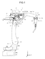
- FIG. 1 is a side view illustrating a robot according to an embodiment.
- FIG. 1 includes a three-dimensional rectangular coordinate system having the Z axis of which the upward vertical direction is defined as the positive direction and the downward vertical direction is defined as the negative direction, the Y axis defined as the horizontal direction on the paper, and the X axis defined as the frontward direction from the back side of the paper.
- Such a rectangular coordinate system is shown in some other drawings used for the description below.
- the description below explains a structure of the robot using the expressions "X axis direction”, “Y axis direction”, and “Z axis direction”. It should be noted that the "X axis direction”, “Y axis direction”, and “Z axis direction” are applied only where the robot is in the posture illustrated in each drawing and are not intended to limit the directions of the robot.
- a robot 1 is an industrial robot for arc welding having a torch 2 for arc welding, for example, attached to an end thereof as an end effector.
- the robot 1 is also an articulated robot including a plurality of joint axes (hereinafter also referred to "rotation axes") Ja to Jf.
- the robot 1 includes a base 10, a rotary section 11, a lower arm 12, an upper arm 13, and a wrist section 14 consisting of a first wrist 14a, a second wrist 14b, and a third wrist 14c, each of which is rotatably connected to each other.
- the rotary section 11 is connected to the base 10 rotatably around the rotation axis Ja
- the lower arm 12 is connected to the rotary section 11 rotatably around the rotation axis Jb that is perpendicular to the rotation axis Ja
- the upper arm 13 is connected to the lower arm 12 rotatably around the rotation axis (a first rotation axis) Jc that is parallel with the rotation axis Jb
- the first wrist 14a is connected to the upper arm 13 rotatably around the rotation axis (a second rotation axis) Jd that is perpendicular to the rotation axis Jc.
- the upper arm 13 corresponds to arm means for rotating about the rotation axis (first rotation axis) Jc
- the first wrist 14a corresponds to wrist means for rotating about the rotation axis (second rotation axis) Jd that is perpendicular to the rotation axis (first rotation axis) Jc.
- the second wrist 14b is connected to the first wrist 14a rotatably around the rotation axis Je that is perpendicular to the rotation axis Jd
- the third wrist 14c is connected to the second wrist 14b rotatably around the rotation axis Jf that is perpendicular to the rotation axis Je.
- the first wrist 14a is connected to the second wrist 14b at a single location to maintain what is called a cantilever structure (see FIG. 2 ).
- perpendicular and parallel in the description above as well as “horizontal” in the description below are not intended to require stringent accuracy in a mathematical sense but shall allow substantial tolerances and errors.
- perpendicular herein used is intended to mean cases where the relation between two straight lines (rotation axes) are skew lines as well as cases where two straight lines (rotation axes) are perpendicular to each other on a plane.
- the robot 1 includes actuators Ma to Mf that rotationally drive the rotary section 11, the lower arm 12, the upper arm 13, the first wrist 14a, the second wrist 14b, and the third wrist 14c described above.
- Each of the actuators Ma to Mf is a servo motor, for example, in concrete terms.
- actuators Ma to Mf are servo motors in the description above, the actuators Ma to Mf should not be limited to servo motors but may be other kind of motors such as hydraulic motors.
- the actuators will be referred to as "motors" in the description below.
- the motor Ma attached to the base 10 is connected to the rotary section 11 to rotationally drive the rotary section 11.
- the motor Mb attached to the rotary section 11 is connected to the lower arm 12 to rotationally drive the lower arm 12.
- the motor Mc attached to the lower arm 12 is connected to the upper arm 13 to rotationally drive the upper arm 13.
- the motor Md is attached to the posterior side of the upper arm 13; specifically, let the side in the upper arm 13 to which the first wrist 14a is connected be the anterior side, the motor Md is attached to the posterior side (the negative side in the Y-axis direction in FIG. 1 ).
- the motor Md is connected to the wrist section 14, specifically, to the first wrist 14a and rotationally drives the first wrist 14a of the wrist section 14 relative to the upper arm 13. The motor Md will be described in detail later.
- the motor Me and the motor Mf both are attached to the first wrist 14a.
- the motor Me is connected to the second wrist 14b via, for example, a pulley not illustrated and rotationally drives the second wrist 14b.
- the motor Mf is connected to the third wrist 14c via, for example, a pulley not illustrated and rotationally drives the third wrist 14c.
- the third wrist 14c includes a wrist flange 14c1 to which the torch 2 described above is attached.
- Input into the motors Ma to Mf described above is a signal representing an operation instruction from a controller (not illustrated). Based on the signal, the operation is controlled. With the operation of the motor Ma to Mf controlled, the robot 1 brings the torch 2 near the object to be welded and generates an arc from the torch 2 while changing the position, the angle, and other conditions of the torch 2, for example, to perform arc welding.
- the robot 1 further includes a feeder 20 that feeds a torch wire (not illustrated in FIG. 1 ) serving as a welding material for arc welding to the torch 2.
- the feeder 20 is disposed on the rear side of the upper arm 13 that is also the upper side in the perpendicular direction of the lower arm 12 (the positive side of the Z axis direction in FIG. 1 ). More specifically, disposed on the upper side in the perpendicular direction of the lower arm 12 is a table 21 including a mounting face that is parallel with the XY axis plane.
- the feeder 20 is attached to the mounting face of the table 21.
- the motor Md is also disposed on the posterior side of the upper arm 13 on which the feeder 20 is disposed. If the motor Md is disposed so as to protrude relatively massively toward the rear from the upper arm 13, therefore, the feeder 20 needs to be offset largely to the rear (in the negative direction of the Y-axis) to a position at which the feeder 20 does not interfere with (contact) the motor Md.
- the robot 1 becomes massive in the longitudinal direction of the upper arm 13, specifically, toward the rear along the rotation axis Jd that is coaxial with the longitudinal direction of the upper arm 13. This may involve an enlarged space for installing the robot 1.
- the motor Md is disposed so that the rotation axis thereof is perpendicular to the rotation axis Jd of the first wrist 14a and is attached to the upper arm 13 so as to extend in the direction of the rotation axis Jc.
- the feeder 20 can be disposed closer to the upper arm 13 side by a reduction in the protruding amount of the motor Md. As a result, the entire robot 1 can be reduced in size and mounting space requirements of the robot 1 can be minimized.
- the robot 1 includes a cable 30 that supplies electric power from a power supply not illustrated to, for example, each of the motors Ma to Mf.
- the cable 30 includes, for example, a plurality of electric wires.
- the cable 30 extending from the power supply is wired inside, for example, the base 10, the rotary section 11, and the lower arm 12 and supplies electric power to, for example, the motors Ma to Mf.
- the cable 30 is wired so as to be once exposed on the outside at an area near a connection in the lower arm 12 to the upper arm 13; thereafter, the cable 30 extends toward a storage 31 disposed on a side surface 13a of the upper arm 13 and is wired to the inside of the upper arm 13.
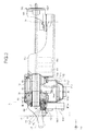
- FIG. 2 is a partial sectional top view illustrating only a vicinity of the upper arm 13, the first wrist 14a, the second wrist 14b, and the third wrist 14c illustrated in FIG. 1 .
- FIG. 2 omits the lower arm 12, the feeder 20, the torch 2, and the like.
- the second wrist 14b having been rotated by 90 degrees around the rotation axis Je to be horizontal, that is, in the posture that the rotation axis Jd is coaxial with the rotation axis Jf.
- the storage 31 includes a storage case 31a and a cover 31b.
- the storage case 31a is disposed on the side surface 13a of the upper arm 13, the storage case 31a having therein a space 32 in which the cable 30 can be stored. Additionally, the storage case 31a has an opening 31a1 formed therein and the cable 30 passes through the opening 31a1.
- the cover 31b has a cutout 31b1 cut out so as to allow the cable 30 to pass therethrough.
- the cover 31b is attached as illustrated in FIG. 2 so as to close the opening 31a1 in the storage case 31a.
- the storage 31, being configured as described above, is formed so as to protrude horizontally from the side surface 13a of the upper arm 13, specifically, so as to protrude to the positive direction in the X-axis direction.
- the cable 30 extending from the lower arm 12 extends past the cutout 31b1 in the cover 31b and is stored in the space 32 by way of the opening 31a1 in the storage case 31a.
- one electric wire 30a is connected to the motor Md and supplies electric power thereto.
- the cable 30 is then wired to extend to the first wrist 14a and connected to the motors Me, Mf disposed at the first wrist 14a to supply electric power thereto.
- the storage 31 that stores therein the cable 30 that extends from the lower arm 12 to the wrist section 14, specifically, to the first wrist 14a is disposed on the side surface 13a of the upper arm 13.
- the cable 30 has so far been described exemplarily as electric wires; nonetheless, the cable may, for example, be one that transmits signals to the motors Ma to Mf or one that transmits signals from encoders disposed at the motors Ma to Mf to a controller.
- FIG. 3 is an end face view taken along line III-III of FIG. 2 .
- FIG. 3 illustrates only the motor Md, the upper arm 13, and a reduction gear to be described later, omitting any other members.
- the motor Md includes an output shaft 40.
- the motor Md exhibits a shape such that the output shaft 40 has a rotation axis Md1 extending in the longitudinal direction of the motor Md.
- a reduction gear 50 is connected to the output shaft 40 of the motor Md. The reduction gear 50 reduces a speed of a driving force of the motor Md and the driving force with the reduced speed is transmitted to the first wrist 14a.
- the output shaft 40 of the motor Md has a bevel gear 41 at a distal end thereof.
- the reduction gear 50 includes an input shaft 51, a main unit 52, and an output shaft 53.
- the input shaft 51 of the reduction gear 50 has a bevel gear 54 mounted at a distal end thereof.
- the bevel gear 54 meshes with the bevel gear 41.
- the main unit 52 houses a reduction mechanism (not illustrated) inserted between the input shaft 51 and the output shaft 53.
- the first wrist 14a is connected to a distal end of the output shaft 53 of the reduction gear 50.
- the driving force of the motor Md is applied via the output shaft 40, the bevel gear 41, and the bevel gear 54 to the input shaft 51 and has its speed reduced by the reduction mechanism.
- the resultant driving force is output to the first wrist 14a from the output shaft 53, so that the first wrist 14a is rotationally drive about the rotation axis Jd.
- the input shaft 51, the main unit 52, the bevel gear 54, the output shaft 53 of the reduction gear 50, and the first to third wrists 14a to 14c are each formed into a hollow shape.
- a conduit cable 60 extending from the feeder 20 to the torch 2 is passed through the inside of the hollow shape.
- the motor Md will be further described.
- the motor Md is disposed so that the rotation axis Md1 of the motor Md is perpendicular to the rotation axis Jd (the second rotation axis) and is attached to the upper arm 13 so as to extend in the direction of the rotation axis Jc (the first rotation axis).
- the motor Md is mounted on the upper arm 13 at a position at which the rotation axis Md1 as the longitudinal direction of the motor Md is perpendicular to the rotation axis Jd and is parallel with the rotation axis Jc.
- the motor Md is disposed on the side surface 13a of the upper arm 13 on the side on which the storage 31 is disposed.
- the motor Md is mounted on the upper arm 13 such that the longitudinal direction thereof protrudes to the positive side in the X-axis direction.
- the motor Md corresponds to drive means for outputting a driving force to rotate the first wrist (the wrist means) 14a, the drive means being attached to the upper arm (the arm means) 13 and having the rotation axis Md1 that is parallel with the rotation axis (the first rotation axis) Jc and is perpendicular to the rotation axis (the second rotation axis) Jd.
- the foregoing arrangements reduce the amount of the motor Md protruding rearwardly from the upper arm 13.
- the feeder 20 can thus be disposed closer to the upper arm 13 side, which reduces the entire robot 1 in size and minimizes the mounting space requirements of the robot 1. Furthermore, disposing the feeder 20 closer to the upper arm 13 side enables a surrounding interfering space in the rear of the robot 1 to be kept small during operation.
- the motor Md is mounted such that the longitudinal direction thereof extends in parallel with the rotation axis Jc in the upper arm 13. To state the foregoing differently, the motor Md is mounted so as to protrude from a side surface, which enhances maintainability. Specifically, while the feeder 20 is disposed on the rear side of the upper arm 13, the motor Md is mounted so as to protrude laterally (on the positive side in the X-axis direction), not toward the rear side on which the feeder 20 is disposed. This facilitates performance of a service job including, for example, replacement of the motor Md with a new one.
- the motor Md is mounted on the storage 31 side in the upper arm 13.
- the motor Md is hidden behind the storage 31. This allows the storage 31 to prevent, for example, a worker from inadvertently contacting the motor Md from the positive side in the Y-axis direction, thus protecting the motor Md.
- the motor Md is attached to the upper arm 13 at a position close to the storage 31. Specifically, the motor Md is disposed so as to be spaced a predetermined slight distance away from a rear side surface of the storage case 31a of the storage 31. To state the foregoing differently, the motor Md is disposed close to, but not in contact with, the side surface of the storage case 31a.
- the motor Md is disposed in an area A (indicated by a dash-double-dot line in FIGS. 1 and 2 ) between the rotation axis (the first rotation axis) Jc and the storage 31. This allows the feeder 20 to be brought to a position close to the area A, even closer to the upper arm 13 side, as illustrated in FIG. 1 , so that the entire robot 1 can be reduced even further in size.
- the motor Md is disposed so that the rotation axis Md1 of the motor Md crosses the rotation axis Jd. This allows the output shaft 40 of the motor Md and the first wrist 14a to be connected to each other with a simple configuration of the bevel gears 41, 54.
- the output shaft 40 of the motor Md and the first wrist 14a require a special gear such as a spiral bevel gear, which complicates the configuration.
- Disposing the motor Md such that the rotation axis Md1 of the motor Md crosses the rotation axis Jd as described above connects the output shaft 40 of the motor Md and the first wrist 14a through the bevel gears 41, 54, which are commonly available, thus achieving a simple configuration.
- the motor Md is disposed so that the rotation axis Md1 of the motor Md extends horizontally, or to state the foregoing differently, extends along the X-axis direction. This allows, for example, the output shaft 40 of the motor Md and the bevel gear 54 of the input shaft 51 of the reduction gear 50 to be lubricated properly.
- the bevel gear 41 and the bevel gear 54 are housed in a gear case 70.
- the gear case 70 has an internal space 70a in which lubricant (not illustrated) is packed.
- the internal space 70a includes an air layer provided in consideration of thermal expansion of the lubricant.
- a sealing member 71 is inserted between the gear case 70 and the motor Md, which seals the internal space 70a of the gear case 70 water-tightly.
- the motor Md has a flat plate 72 inserted between the main unit of the motor Md and the sealing member 71.
- the flat plate 72 detects leakage of the lubricant as will be later described.
- FIG. 4 is a cross-sectional view taken along line IV-IV of FIG. 2 , illustrating the flat plate 72.
- FIG. 4 illustrates only the flat plate 72 and the output shaft 40 of the motor Md.
- the flat plate 72 exhibits a rectangular shape as viewed in the X-axis direction.
- the flat plate 72 has a pass-through hole 72a pierced at a central portion thereof, the pass-through hole 72a receiving the output shaft 40 passed therethrough.
- the flat plate 72 further has a plurality of (e.g., four) flow paths 72b extending radially from the center of the pass-through hole 72a. Specifically, the four flow paths 72b are formed to be spaced at intervals of 90 degrees apart from each other.
- the flat plate 72 is disposed so that at least one of the flow paths 72b has a flow direction extending in parallel with the vertical direction (Z-axis direction).
- the rotation axis Md1 does not extend horizontally, parts of the bevel gear 41 and the bevel gear 54 may not be lubricated by the lubricant depending on the position of the air layer in the internal space 70a.
- the rotation axis Md1 does not extend horizontally, but extends in parallel with the vertical direction, and if the lubricant leaks out from the sealing member 71, the leaked lubricant flows from the output shaft 40 to the main unit of the motor Md, which may cause the motor Md to malfunction.
- disposing the motor Md with the rotation axis Md1 extending horizontally allows the bevel gear 41 and the bevel gear 54 to be evenly wet in the lubricant, so that the gears can be lubricated appropriately.
- the leaked lubricant flows from the output shaft 40 to the flat plate 72 and out via the flow paths 72b in the flat plate 72. This eliminates the likelihood that the leaked lubricant will flow from the output shaft 40 to the main unit of the motor Md and will be a cause of a motor Md malfunction. Additionally, an inspector of the robot 1, for example, can easily check for a possible leak of lubricant by simply visually checking outlets of the flow paths 72b of the flat plate 72.
- the flat plate 72 does not need to be shaped as illustrated in FIG. 4 , but may be shaped differently.
- the flow paths 72b of the flat plate 72 do not need to be oriented as illustrated in FIG. 4 , but may be oriented at a predetermined angle relative to the Z-axis direction. Additionally, in the embodiment, the flat plate 72 has four flow paths 72b; nonetheless, the flat plate 72 may have, for example, three or less, or five or more, flow paths 72b.
- the motor Md is disposed so that the rotation axis Md1 of the motor Md is perpendicular to the rotation axis Jd of the first wrist 14a and is attached to the upper arm 13 so as to extend in the direction of the rotation axis Jc of the upper arm 13. This reduces the entire robot 1 in size and minimizes the mounting space requirements of the robot 1.
- connection part between the first wrist 14a and the second wrist 14b has a cantilever structure.
- the embodiment is not limited thereto.
- the first wrist 14a and the second wrist 14b may be connected as illustrated in FIG. 5 .
- the connection part between the first wrist 14a and the second wrist 14b may form a center impeller structure in which the first wrist 14a is formed into a fork shape on one side to which the second wrist 14b is connected and the fork-shaped region rotatably supports the second wrist 14b from both sides, as illustrated in FIG. 5 .
- the robot 1 is configured as a robot for arc welding. However, the embodiment is not limited to such a configuration.
- the robot 1 may be other type of robot.
- the robot 1 includes the torch 2 as an end effecter in the configuration described above, the robot may include a hand for holding a workpiece or an suction section for sucking and retaining a workpiece as an end effector and perform operations such as delivery of the workpiece using the hand or other part.
- a control box that houses therein a valve and the like used for controlling the hand or the suction section is disposed in the rear of the upper arm 13.
- the robot 1 has been described as a six-axis robot. However, the embodiment is not limited to such a configuration. A robot that has a structure other than a six-axis structure, for example, a seven-axis or an eight-axis robot may be used.
Landscapes
- Engineering & Computer Science (AREA)
- Robotics (AREA)
- Mechanical Engineering (AREA)
- Manipulator (AREA)
Abstract
Description
- The embodiment discussed herein is directed to a robot.
- A known industrial robot includes, for example, a lower arm, an upper arm connected rotatably relative to the lower arm, and a wrist connected rotatably relative to the upper arm, the wrist and the like being rotatable by an actuator (see, for example, Japanese Patent No.
4529456 - In the technique disclosed in Japanese Patent No.
4529456 4529456 - A device of a type depending on work performed by a robot is disposed on the posterior side of the upper arm. Specifically, if, for example, the robot performs an arc welding job, a feeder that feeds a torch wire to a leading end of the robot is disposed.
- In the technique disclosed in Japanese Patent No.
4529456 - An embodiment has been made in view of the foregoing situation and it is an object of the embodiment to provide a robot that can achieve reduction in size of the entire robot and require a small space for installation.
- According to one aspect of an embodiment, a robot includes a lower arm, an upper arm, a wrist, and an actuator. The upper arm is connected to the lower arm rotatably about a first rotation axis. The wrist is connected to the upper arm rotatably about a second rotation axis perpendicular to the first rotation axis. The actuator is attached to the upper arm, the actuator rotationally drives the wrist. The actuator is disposed so that a rotation axis of the actuator is perpendicular to the second rotation axis and is attached to the upper arm so as to extend in a direction of the first rotation axis.
- According to one aspect of the embodiment, the entire robot can be reduced in size and the mounting space requirements of the robot can be minimized.
- A more complete appreciation of the invention and many of the attendant advantages thereof will be readily obtained as the same becomes better understood by reference to the following detailed description when considered in connection with the accompanying drawings, wherein:
-
FIG. 1 is a side view illustrating a robot according to an embodiment; -
FIG. 2 is a partial sectional top view illustrating only a vicinity of an upper arm, a first wrist, a second wrist, and a third wrist illustrated inFIG. 1 ; -
FIG. 3 is an end face view taken along line III-III ofFIG. 2 ; -
FIG. 4 is a cross-sectional view taken along line IV-IV ofFIG. 2 ; and -
FIG. 5 is a partial sectional top view illustrating only a vicinity of an upper arm, a first wrist, a second wrist, and a third wrist in a modification of the robot according to the embodiment. -
FIG. 1 is a side view illustrating a robot according to an embodiment. For the sake of explanation,FIG. 1 includes a three-dimensional rectangular coordinate system having the Z axis of which the upward vertical direction is defined as the positive direction and the downward vertical direction is defined as the negative direction, the Y axis defined as the horizontal direction on the paper, and the X axis defined as the frontward direction from the back side of the paper. Such a rectangular coordinate system is shown in some other drawings used for the description below. In addition, the description below explains a structure of the robot using the expressions "X axis direction", "Y axis direction", and "Z axis direction". It should be noted that the "X axis direction", "Y axis direction", and "Z axis direction" are applied only where the robot is in the posture illustrated in each drawing and are not intended to limit the directions of the robot. - As illustrated in
FIG. 1 , a robot 1 is an industrial robot for arc welding having atorch 2 for arc welding, for example, attached to an end thereof as an end effector. The robot 1 is also an articulated robot including a plurality of joint axes (hereinafter also referred to "rotation axes") Ja to Jf. The robot 1 includes abase 10, arotary section 11, alower arm 12, anupper arm 13, and awrist section 14 consisting of afirst wrist 14a, asecond wrist 14b, and athird wrist 14c, each of which is rotatably connected to each other. - Specifically, the
rotary section 11 is connected to thebase 10 rotatably around the rotation axis Ja, and thelower arm 12 is connected to therotary section 11 rotatably around the rotation axis Jb that is perpendicular to the rotation axis Ja. Theupper arm 13 is connected to thelower arm 12 rotatably around the rotation axis (a first rotation axis) Jc that is parallel with the rotation axis Jb, and thefirst wrist 14a is connected to theupper arm 13 rotatably around the rotation axis (a second rotation axis) Jd that is perpendicular to the rotation axis Jc. As such, theupper arm 13 corresponds to arm means for rotating about the rotation axis (first rotation axis) Jc. Similarly, thefirst wrist 14a corresponds to wrist means for rotating about the rotation axis (second rotation axis) Jd that is perpendicular to the rotation axis (first rotation axis) Jc. - The
second wrist 14b is connected to thefirst wrist 14a rotatably around the rotation axis Je that is perpendicular to the rotation axis Jd, and thethird wrist 14c is connected to thesecond wrist 14b rotatably around the rotation axis Jf that is perpendicular to the rotation axis Je. Thefirst wrist 14a is connected to thesecond wrist 14b at a single location to maintain what is called a cantilever structure (seeFIG. 2 ). - It should be noted that the terms "perpendicular" and "parallel" in the description above as well as "horizontal" in the description below are not intended to require stringent accuracy in a mathematical sense but shall allow substantial tolerances and errors. In addition, the term "perpendicular" herein used is intended to mean cases where the relation between two straight lines (rotation axes) are skew lines as well as cases where two straight lines (rotation axes) are perpendicular to each other on a plane.
- The robot 1 includes actuators Ma to Mf that rotationally drive the
rotary section 11, thelower arm 12, theupper arm 13, thefirst wrist 14a, thesecond wrist 14b, and thethird wrist 14c described above. Each of the actuators Ma to Mf is a servo motor, for example, in concrete terms. - Although the actuators Ma to Mf are servo motors in the description above, the actuators Ma to Mf should not be limited to servo motors but may be other kind of motors such as hydraulic motors. The actuators will be referred to as "motors" in the description below.
- To explain each of the motors Ma to Mf, the motor Ma attached to the
base 10 is connected to therotary section 11 to rotationally drive therotary section 11. The motor Mb attached to therotary section 11 is connected to thelower arm 12 to rotationally drive thelower arm 12. The motor Mc attached to thelower arm 12 is connected to theupper arm 13 to rotationally drive theupper arm 13. - The motor Md is attached to the posterior side of the
upper arm 13; specifically, let the side in theupper arm 13 to which thefirst wrist 14a is connected be the anterior side, the motor Md is attached to the posterior side (the negative side in the Y-axis direction inFIG. 1 ). The motor Md is connected to thewrist section 14, specifically, to thefirst wrist 14a and rotationally drives thefirst wrist 14a of thewrist section 14 relative to theupper arm 13. The motor Md will be described in detail later. - The motor Me and the motor Mf both are attached to the
first wrist 14a. The motor Me is connected to thesecond wrist 14b via, for example, a pulley not illustrated and rotationally drives thesecond wrist 14b. Similarly, the motor Mf is connected to thethird wrist 14c via, for example, a pulley not illustrated and rotationally drives thethird wrist 14c. Thethird wrist 14c includes a wrist flange 14c1 to which thetorch 2 described above is attached. - Input into the motors Ma to Mf described above is a signal representing an operation instruction from a controller (not illustrated). Based on the signal, the operation is controlled. With the operation of the motor Ma to Mf controlled, the robot 1 brings the
torch 2 near the object to be welded and generates an arc from thetorch 2 while changing the position, the angle, and other conditions of thetorch 2, for example, to perform arc welding. - The robot 1 further includes a
feeder 20 that feeds a torch wire (not illustrated inFIG. 1 ) serving as a welding material for arc welding to thetorch 2. Thefeeder 20 is disposed on the rear side of theupper arm 13 that is also the upper side in the perpendicular direction of the lower arm 12 (the positive side of the Z axis direction inFIG. 1 ). More specifically, disposed on the upper side in the perpendicular direction of thelower arm 12 is a table 21 including a mounting face that is parallel with the XY axis plane. Thefeeder 20 is attached to the mounting face of the table 21. - As described earlier, the motor Md is also disposed on the posterior side of the
upper arm 13 on which thefeeder 20 is disposed. If the motor Md is disposed so as to protrude relatively massively toward the rear from theupper arm 13, therefore, thefeeder 20 needs to be offset largely to the rear (in the negative direction of the Y-axis) to a position at which thefeeder 20 does not interfere with (contact) the motor Md. - In the foregoing case, the robot 1 becomes massive in the longitudinal direction of the
upper arm 13, specifically, toward the rear along the rotation axis Jd that is coaxial with the longitudinal direction of theupper arm 13. This may involve an enlarged space for installing the robot 1. - Thus, in the robot 1 according to the embodiment, the motor Md is disposed so that the rotation axis thereof is perpendicular to the rotation axis Jd of the
first wrist 14a and is attached to theupper arm 13 so as to extend in the direction of the rotation axis Jc. - This prevents the motor Md from protruding relatively massively rearwardly from the
upper arm 13 and reduces a rearward protruding amount. Thus, for example, thefeeder 20 can be disposed closer to theupper arm 13 side by a reduction in the protruding amount of the motor Md. As a result, the entire robot 1 can be reduced in size and mounting space requirements of the robot 1 can be minimized. - Descriptions with reference to
FIG. 1 will continue. The robot 1 includes acable 30 that supplies electric power from a power supply not illustrated to, for example, each of the motors Ma to Mf. Thecable 30 includes, for example, a plurality of electric wires. - Although not illustrated, the
cable 30 extending from the power supply is wired inside, for example, thebase 10, therotary section 11, and thelower arm 12 and supplies electric power to, for example, the motors Ma to Mf. Referring toFIG. 1 , thecable 30 is wired so as to be once exposed on the outside at an area near a connection in thelower arm 12 to theupper arm 13; thereafter, thecable 30 extends toward astorage 31 disposed on aside surface 13a of theupper arm 13 and is wired to the inside of theupper arm 13. -
FIG. 2 is a partial sectional top view illustrating only a vicinity of theupper arm 13, thefirst wrist 14a, thesecond wrist 14b, and thethird wrist 14c illustrated inFIG. 1 . For simplification purpose,FIG. 2 omits thelower arm 12, thefeeder 20, thetorch 2, and the like. Furthermore, illustrated inFIG. 2 is thesecond wrist 14b having been rotated by 90 degrees around the rotation axis Je to be horizontal, that is, in the posture that the rotation axis Jd is coaxial with the rotation axis Jf. - As illustrated in
FIG. 2 , thestorage 31 includes astorage case 31a and acover 31b. Thestorage case 31a is disposed on theside surface 13a of theupper arm 13, thestorage case 31a having therein aspace 32 in which thecable 30 can be stored. Additionally, thestorage case 31a has an opening 31a1 formed therein and thecable 30 passes through the opening 31a1. Thecover 31b has a cutout 31b1 cut out so as to allow thecable 30 to pass therethrough. Thecover 31b is attached as illustrated inFIG. 2 so as to close the opening 31a1 in thestorage case 31a. - The
storage 31, being configured as described above, is formed so as to protrude horizontally from theside surface 13a of theupper arm 13, specifically, so as to protrude to the positive direction in the X-axis direction. - The
cable 30 extending from thelower arm 12 extends past the cutout 31b1 in thecover 31b and is stored in thespace 32 by way of the opening 31a1 in thestorage case 31a. Of the electric wires constituting thecable 30, oneelectric wire 30a is connected to the motor Md and supplies electric power thereto. Thecable 30 is then wired to extend to thefirst wrist 14a and connected to the motors Me, Mf disposed at thefirst wrist 14a to supply electric power thereto. - As described above, the
storage 31 that stores therein thecable 30 that extends from thelower arm 12 to thewrist section 14, specifically, to thefirst wrist 14a is disposed on theside surface 13a of theupper arm 13. Thecable 30 has so far been described exemplarily as electric wires; nonetheless, the cable may, for example, be one that transmits signals to the motors Ma to Mf or one that transmits signals from encoders disposed at the motors Ma to Mf to a controller. - The motor Md will be described in detail below.
FIG. 3 is an end face view taken along line III-III ofFIG. 2 . For simplification purpose,FIG. 3 illustrates only the motor Md, theupper arm 13, and a reduction gear to be described later, omitting any other members. - The motor Md includes an
output shaft 40. The motor Md exhibits a shape such that theoutput shaft 40 has a rotation axis Md1 extending in the longitudinal direction of the motor Md. Areduction gear 50 is connected to theoutput shaft 40 of the motor Md. Thereduction gear 50 reduces a speed of a driving force of the motor Md and the driving force with the reduced speed is transmitted to thefirst wrist 14a. - Specifically, the
output shaft 40 of the motor Md has abevel gear 41 at a distal end thereof. Meanwhile, thereduction gear 50 includes aninput shaft 51, amain unit 52, and anoutput shaft 53. Theinput shaft 51 of thereduction gear 50 has abevel gear 54 mounted at a distal end thereof. Thebevel gear 54 meshes with thebevel gear 41. Themain unit 52 houses a reduction mechanism (not illustrated) inserted between theinput shaft 51 and theoutput shaft 53. Additionally, thefirst wrist 14a is connected to a distal end of theoutput shaft 53 of thereduction gear 50. - Thus, the driving force of the motor Md is applied via the
output shaft 40, thebevel gear 41, and thebevel gear 54 to theinput shaft 51 and has its speed reduced by the reduction mechanism. The resultant driving force is output to thefirst wrist 14a from theoutput shaft 53, so that thefirst wrist 14a is rotationally drive about the rotation axis Jd. - As illustrated in
FIG. 2 , theinput shaft 51, themain unit 52, thebevel gear 54, theoutput shaft 53 of thereduction gear 50, and the first tothird wrists 14a to 14c are each formed into a hollow shape. Aconduit cable 60 extending from thefeeder 20 to thetorch 2 is passed through the inside of the hollow shape. - The motor Md will be further described. The motor Md is disposed so that the rotation axis Md1 of the motor Md is perpendicular to the rotation axis Jd (the second rotation axis) and is attached to the
upper arm 13 so as to extend in the direction of the rotation axis Jc (the first rotation axis). To state the foregoing differently, the motor Md is mounted on theupper arm 13 at a position at which the rotation axis Md1 as the longitudinal direction of the motor Md is perpendicular to the rotation axis Jd and is parallel with the rotation axis Jc. Additionally, the motor Md is disposed on theside surface 13a of theupper arm 13 on the side on which thestorage 31 is disposed. As such, the motor Md is mounted on theupper arm 13 such that the longitudinal direction thereof protrudes to the positive side in the X-axis direction. Specifically, the motor Md corresponds to drive means for outputting a driving force to rotate the first wrist (the wrist means) 14a, the drive means being attached to the upper arm (the arm means) 13 and having the rotation axis Md1 that is parallel with the rotation axis (the first rotation axis) Jc and is perpendicular to the rotation axis (the second rotation axis) Jd. - The foregoing arrangements reduce the amount of the motor Md protruding rearwardly from the
upper arm 13. Thefeeder 20 can thus be disposed closer to theupper arm 13 side, which reduces the entire robot 1 in size and minimizes the mounting space requirements of the robot 1. Furthermore, disposing thefeeder 20 closer to theupper arm 13 side enables a surrounding interfering space in the rear of the robot 1 to be kept small during operation. - The motor Md is mounted such that the longitudinal direction thereof extends in parallel with the rotation axis Jc in the
upper arm 13. To state the foregoing differently, the motor Md is mounted so as to protrude from a side surface, which enhances maintainability. Specifically, while thefeeder 20 is disposed on the rear side of theupper arm 13, the motor Md is mounted so as to protrude laterally (on the positive side in the X-axis direction), not toward the rear side on which thefeeder 20 is disposed. This facilitates performance of a service job including, for example, replacement of the motor Md with a new one. - In addition, the motor Md is mounted on the
storage 31 side in theupper arm 13. Thus, when viewed from the positive side in the Y-axis direction, the motor Md is hidden behind thestorage 31. This allows thestorage 31 to prevent, for example, a worker from inadvertently contacting the motor Md from the positive side in the Y-axis direction, thus protecting the motor Md. - The motor Md is attached to the
upper arm 13 at a position close to thestorage 31. Specifically, the motor Md is disposed so as to be spaced a predetermined slight distance away from a rear side surface of thestorage case 31a of thestorage 31. To state the foregoing differently, the motor Md is disposed close to, but not in contact with, the side surface of thestorage case 31a. - This enlarges a space rearward of the
upper arm 13, so that thefeeder 20 can be disposed even closer to theupper arm 13 side. The entire robot 1 can thereby be reduced further in size. - The motor Md is disposed in an area A (indicated by a dash-double-dot line in
FIGS. 1 and2 ) between the rotation axis (the first rotation axis) Jc and thestorage 31. This allows thefeeder 20 to be brought to a position close to the area A, even closer to theupper arm 13 side, as illustrated inFIG. 1 , so that the entire robot 1 can be reduced even further in size. - As illustrated in
FIG. 3 , the motor Md is disposed so that the rotation axis Md1 of the motor Md crosses the rotation axis Jd. This allows theoutput shaft 40 of the motor Md and thefirst wrist 14a to be connected to each other with a simple configuration of the bevel gears 41, 54. - Specifically, if the rotation axis Md1 of the motor Md is arranged so as not to cross the rotation axis Jd, the
output shaft 40 of the motor Md and thefirst wrist 14a (theinput shaft 51 of thereduction gear 50 to be more precise) require a special gear such as a spiral bevel gear, which complicates the configuration. Disposing the motor Md such that the rotation axis Md1 of the motor Md crosses the rotation axis Jd as described above connects theoutput shaft 40 of the motor Md and thefirst wrist 14a through the bevel gears 41, 54, which are commonly available, thus achieving a simple configuration. - The motor Md is disposed so that the rotation axis Md1 of the motor Md extends horizontally, or to state the foregoing differently, extends along the X-axis direction. This allows, for example, the
output shaft 40 of the motor Md and thebevel gear 54 of theinput shaft 51 of thereduction gear 50 to be lubricated properly. - More specifically, referring to
FIG. 2 , thebevel gear 41 and thebevel gear 54 are housed in agear case 70. Thegear case 70 has aninternal space 70a in which lubricant (not illustrated) is packed. Theinternal space 70a includes an air layer provided in consideration of thermal expansion of the lubricant. - A sealing
member 71 is inserted between thegear case 70 and the motor Md, which seals theinternal space 70a of thegear case 70 water-tightly. The motor Md has aflat plate 72 inserted between the main unit of the motor Md and the sealingmember 71. Theflat plate 72 detects leakage of the lubricant as will be later described. -
FIG. 4 is a cross-sectional view taken along line IV-IV ofFIG. 2 , illustrating theflat plate 72. For simplification purpose,FIG. 4 illustrates only theflat plate 72 and theoutput shaft 40 of the motor Md. As illustrated inFIG. 4 , theflat plate 72 exhibits a rectangular shape as viewed in the X-axis direction. Theflat plate 72 has a pass-throughhole 72a pierced at a central portion thereof, the pass-throughhole 72a receiving theoutput shaft 40 passed therethrough. Theflat plate 72 further has a plurality of (e.g., four)flow paths 72b extending radially from the center of the pass-throughhole 72a. Specifically, the fourflow paths 72b are formed to be spaced at intervals of 90 degrees apart from each other. Theflat plate 72 is disposed so that at least one of theflow paths 72b has a flow direction extending in parallel with the vertical direction (Z-axis direction). - In the motor Md having the arrangements as described above, if, for example, the rotation axis Md1 does not extend horizontally, parts of the
bevel gear 41 and thebevel gear 54 may not be lubricated by the lubricant depending on the position of the air layer in theinternal space 70a. In addition, in the motor Md, if, for example, the rotation axis Md1 does not extend horizontally, but extends in parallel with the vertical direction, and if the lubricant leaks out from the sealingmember 71, the leaked lubricant flows from theoutput shaft 40 to the main unit of the motor Md, which may cause the motor Md to malfunction. - Thus, in the embodiment, disposing the motor Md with the rotation axis Md1 extending horizontally allows the
bevel gear 41 and thebevel gear 54 to be evenly wet in the lubricant, so that the gears can be lubricated appropriately. - Should the lubricant in the
gear case 70 leak from the sealingmember 71, the leaked lubricant flows from theoutput shaft 40 to theflat plate 72 and out via theflow paths 72b in theflat plate 72. This eliminates the likelihood that the leaked lubricant will flow from theoutput shaft 40 to the main unit of the motor Md and will be a cause of a motor Md malfunction. Additionally, an inspector of the robot 1, for example, can easily check for a possible leak of lubricant by simply visually checking outlets of theflow paths 72b of theflat plate 72. - The
flat plate 72 does not need to be shaped as illustrated inFIG. 4 , but may be shaped differently. Theflow paths 72b of theflat plate 72 do not need to be oriented as illustrated inFIG. 4 , but may be oriented at a predetermined angle relative to the Z-axis direction. Additionally, in the embodiment, theflat plate 72 has fourflow paths 72b; nonetheless, theflat plate 72 may have, for example, three or less, or five or more, flowpaths 72b. - As described above, the motor Md is disposed so that the rotation axis Md1 of the motor Md is perpendicular to the rotation axis Jd of the
first wrist 14a and is attached to theupper arm 13 so as to extend in the direction of the rotation axis Jc of theupper arm 13. This reduces the entire robot 1 in size and minimizes the mounting space requirements of the robot 1. - In the robot 1, the connection part between the
first wrist 14a and thesecond wrist 14b has a cantilever structure. However, the embodiment is not limited thereto. For example, thefirst wrist 14a and thesecond wrist 14b may be connected as illustrated inFIG. 5 . More specifically, the connection part between thefirst wrist 14a and thesecond wrist 14b may form a center impeller structure in which thefirst wrist 14a is formed into a fork shape on one side to which thesecond wrist 14b is connected and the fork-shaped region rotatably supports thesecond wrist 14b from both sides, as illustrated inFIG. 5 . - The robot 1 is configured as a robot for arc welding. However, the embodiment is not limited to such a configuration. The robot 1 may be other type of robot. Specifically, although the robot 1 includes the
torch 2 as an end effecter in the configuration described above, the robot may include a hand for holding a workpiece or an suction section for sucking and retaining a workpiece as an end effector and perform operations such as delivery of the workpiece using the hand or other part. In this case, in place of thefeeder 20, for example, a control box that houses therein a valve and the like used for controlling the hand or the suction section is disposed in the rear of theupper arm 13. - The robot 1 has been described as a six-axis robot. However, the embodiment is not limited to such a configuration. A robot that has a structure other than a six-axis structure, for example, a seven-axis or an eight-axis robot may be used.
Claims (5)
- A robot (1) comprising:a lower arm (12);an upper arm (13) connected to the lower arm (12) rotatably about a first rotation axis (Jc);a wrist (14) connected to the upper arm (13) rotatably about a second rotation axis (Jd) perpendicular to the first rotation axis (Jc); andan actuator (Md) attached to the upper arm (13), the actuator (Md) rotationally driving the wrist (14), whereinthe actuator (Md) is disposed so that a rotation axis (Md1) of the actuator (Md) is perpendicular to the second rotation axis (Jd) and is attached to the upper arm (13) so as to extend in a direction of the first rotation axis (Jc).
- The robot (1) according to claim 1, further comprising:a storage (31) disposed on a side surface (13a) of the upper arm (13), the storage (31) storing therein a cable (30) that extends from the lower arm (12) toward the wrist (14), whereinthe actuator (Md) is disposed on the side surface (13a) of the upper arm (13) on which the storage (31) is disposed.
- The robot (1) according to claim 1 or 2, wherein the actuator (Md) is disposed so that the rotation axis (Md1) of the actuator (Md) crosses the second rotation axis (Jd).
- The robot (1) according to claim 2 or 3, wherein the actuator (Md) is disposed in an area (A) between the first rotation axis (Jc) and the storage (31).
- The robot (1) according to any one of claims 2 to 4, wherein the actuator (Md) is attached to the upper arm (13) at a position close to the storage (31).
Applications Claiming Priority (1)
| Application Number | Priority Date | Filing Date | Title |
|---|---|---|---|
| JP2013005983A JP5413524B1 (en) | 2013-01-17 | 2013-01-17 | robot |
Publications (3)
| Publication Number | Publication Date |
|---|---|
| EP2756930A2 true EP2756930A2 (en) | 2014-07-23 |
| EP2756930A3 EP2756930A3 (en) | 2018-04-18 |
| EP2756930B1 EP2756930B1 (en) | 2019-07-24 |
Family
ID=49949537
Family Applications (1)
| Application Number | Title | Priority Date | Filing Date |
|---|---|---|---|
| EP14151051.1A Active EP2756930B1 (en) | 2013-01-17 | 2014-01-14 | Robot |
Country Status (4)
| Country | Link |
|---|---|
| US (1) | US9481095B2 (en) |
| EP (1) | EP2756930B1 (en) |
| JP (1) | JP5413524B1 (en) |
| CN (1) | CN103934832B (en) |
Cited By (1)
| Publication number | Priority date | Publication date | Assignee | Title |
|---|---|---|---|---|
| US10081101B2 (en) | 2016-04-04 | 2018-09-25 | Fanuc Corporation | Robot arm |
Families Citing this family (14)
| Publication number | Priority date | Publication date | Assignee | Title |
|---|---|---|---|---|
| JP5413524B1 (en) * | 2013-01-17 | 2014-02-12 | 株式会社安川電機 | robot |
| JP5928416B2 (en) | 2013-07-26 | 2016-06-01 | 株式会社安川電機 | Robot and robot manufacturing method |
| CN104339365B (en) * | 2013-07-26 | 2017-04-12 | 株式会社安川电机 | Robot and manufacturing method of same |
| JP5884785B2 (en) * | 2013-07-30 | 2016-03-15 | 株式会社安川電機 | robot |
| JP5975129B1 (en) | 2015-03-02 | 2016-08-23 | 株式会社安川電機 | robot |
| JP6572270B2 (en) * | 2017-09-08 | 2019-09-04 | ファナック株式会社 | Robot with hollow wrist element |
| JP2019048360A (en) * | 2017-09-12 | 2019-03-28 | セイコーエプソン株式会社 | Robot and robot system |
| JP2019084608A (en) * | 2017-11-06 | 2019-06-06 | セイコーエプソン株式会社 | Robot and robot system |
| JP6730352B2 (en) * | 2018-03-20 | 2020-07-29 | ファナック株式会社 | Cable clamps and robots |
| JP6810102B2 (en) * | 2018-07-04 | 2021-01-06 | ファナック株式会社 | Robot wrist structure |
| JP6978450B2 (en) * | 2019-01-29 | 2021-12-08 | ファナック株式会社 | robot |
| US11266366B2 (en) * | 2019-11-20 | 2022-03-08 | GE Precision Healthcare LLC | Methods and systems for C-arm cable management |
| CN114310959B (en) * | 2022-01-10 | 2024-09-20 | 南通大学 | Amphibious garbage cleaning robot |
| WO2025189425A1 (en) * | 2024-03-14 | 2025-09-18 | Abb Schweiz Ag | A wrist joint for an industrial robot |
Citations (1)
| Publication number | Priority date | Publication date | Assignee | Title |
|---|---|---|---|---|
| JP4529456B2 (en) | 2003-11-28 | 2010-08-25 | 株式会社安川電機 | Arm mechanism of industrial robot |
Family Cites Families (48)
| Publication number | Priority date | Publication date | Assignee | Title |
|---|---|---|---|---|
| JPS6020877A (en) * | 1983-07-13 | 1985-02-02 | 三菱電機株式会社 | Industrial robot |
| JPS6022293U (en) * | 1983-07-21 | 1985-02-15 | 大日機工株式会社 | Industrial robot wrist structure |
| DE3434899A1 (en) * | 1983-10-19 | 1985-05-23 | Kuka Schweissanlagen + Roboter Gmbh, 8900 Augsburg | DEVICE FOR OUTSIDE HOLDING AND LEADING SUPPLY CABLES TO MOVING TOOLS OF MANIPULATORS |
| JPS6144591A (en) * | 1984-08-07 | 1986-03-04 | 株式会社不二越 | Robot |
| JPH0645019Y2 (en) * | 1987-08-05 | 1994-11-16 | 株式会社ニフコ | Closure structure of lid |
| JPH0326487U (en) | 1989-07-20 | 1991-03-18 | ||
| JP2921132B2 (en) * | 1991-01-31 | 1999-07-19 | 株式会社安川電機 | Industrial robot wrist mechanism |
| SE514034C2 (en) * | 1994-01-26 | 2000-12-11 | Abb Ab | Wiring between junction boxes inside a robot for power transmission to motors and control systems |
| JP3480533B2 (en) * | 1995-08-30 | 2003-12-22 | 株式会社安川電機 | Robot joint mechanism |
| JPH10175188A (en) * | 1996-12-17 | 1998-06-30 | Fanuc Ltd | Robot structure |
| DE29814417U1 (en) * | 1998-08-11 | 1998-10-08 | Kuka Roboter GmbH, 86165 Augsburg | Hose holder |
| JP2002283275A (en) * | 2001-03-21 | 2002-10-03 | Fanuc Ltd | Wrist structure of robot |
| JP4142304B2 (en) * | 2001-10-22 | 2008-09-03 | 株式会社安川電機 | Arc welding robot |
| JP4099628B2 (en) * | 2001-10-29 | 2008-06-11 | 株式会社安川電機 | Industrial robot |
| JP2003305682A (en) * | 2002-04-11 | 2003-10-28 | Fanuc Ltd | Robot wrist drive mechanism |
| ATE495860T1 (en) * | 2003-02-07 | 2011-02-15 | Kawasaki Heavy Ind Ltd | MULTI-JOINT MANIPULATOR |
| JP4286684B2 (en) * | 2004-02-27 | 2009-07-01 | 株式会社ダイヘン | Cable arrangement structure for arc welding robot |
| JP4168008B2 (en) * | 2004-06-04 | 2008-10-22 | ファナック株式会社 | Striated structure of industrial robot |
| JP3987845B2 (en) * | 2004-08-13 | 2007-10-10 | ファナック株式会社 | Striated structure of industrial robot |
| JP2006150496A (en) * | 2004-11-29 | 2006-06-15 | Fanuc Ltd | Wire-shaped body supporting device for robot, and robot provided with wire-shaped body supporting device |
| JP4038217B2 (en) * | 2005-07-14 | 2008-01-23 | ファナック株式会社 | Striated structure of industrial robot |
| JP4233578B2 (en) * | 2006-08-10 | 2009-03-04 | ファナック株式会社 | Wrist drive structure of industrial robot |
| JP4326558B2 (en) * | 2006-08-24 | 2009-09-09 | ファナック株式会社 | Drive mechanism of industrial robot arm |
| ATE496739T1 (en) * | 2006-12-27 | 2011-02-15 | Abb Ab | INDUSTRIAL ROBOT WITH TUBE ELEMENT FOR A CABLE HARNESS |
| WO2008084737A1 (en) * | 2007-01-09 | 2008-07-17 | Kabushiki Kaisha Yaskawa Denki | Industrial robot |
| JP2008238320A (en) * | 2007-03-27 | 2008-10-09 | Fanuc Ltd | Robot having working tool |
| JP4280295B2 (en) * | 2007-06-20 | 2009-06-17 | ファナック株式会社 | Industrial robot |
| JP4261598B2 (en) * | 2007-07-30 | 2009-04-30 | ファナック株式会社 | Striated structure of industrial robot |
| JP5180621B2 (en) * | 2008-03-04 | 2013-04-10 | 本田技研工業株式会社 | Articulated robot |
| JP5115309B2 (en) * | 2008-04-28 | 2013-01-09 | 株式会社安川電機 | Industrial robot and method of operation |
| JP4565029B2 (en) * | 2008-08-13 | 2010-10-20 | ファナック株式会社 | Striated body motion restriction device and robot equipped with the device |
| FR2937269B1 (en) * | 2008-10-17 | 2010-10-29 | Staubli Sa Ets | ARTICULATED MULTI-AXIS ROBOT STRUCTURE AND ROBOT COMPRISING SUCH A STRUCTURE |
| DE102009043448A1 (en) * | 2009-09-29 | 2011-04-07 | Siemens Aktiengesellschaft | robotic assembly |
| CN102069493A (en) * | 2009-11-19 | 2011-05-25 | 鸿富锦精密工业(深圳)有限公司 | Arm part of robot and robot |
| CN102079089A (en) * | 2009-11-30 | 2011-06-01 | 鸿富锦精密工业(深圳)有限公司 | Robot |
| JP5457922B2 (en) * | 2010-04-14 | 2014-04-02 | 株式会社ダイヘン | Industrial robot |
| JP5450222B2 (en) * | 2010-04-14 | 2014-03-26 | 株式会社ダイヘン | Reference positioning method for arm of industrial robot and industrial robot |
| JP5450223B2 (en) * | 2010-04-14 | 2014-03-26 | 株式会社ダイヘン | Industrial robot |
| CN102259337B (en) * | 2010-05-28 | 2013-11-06 | 鸿富锦精密工业(深圳)有限公司 | Robot arm component |
| JP5344315B2 (en) * | 2010-11-04 | 2013-11-20 | 株式会社安川電機 | Robot wrist structure and robot |
| JP5387611B2 (en) * | 2011-04-19 | 2014-01-15 | 株式会社安川電機 | Drive mechanism and robot |
| WO2012157169A1 (en) * | 2011-05-13 | 2012-11-22 | 川崎重工業株式会社 | Multijoint industrial robot |
| JP5833836B2 (en) * | 2011-05-13 | 2015-12-16 | 川崎重工業株式会社 | Articulated industrial robot |
| JP5434991B2 (en) * | 2011-09-01 | 2014-03-05 | 株式会社安川電機 | robot |
| JP5423750B2 (en) * | 2011-09-27 | 2014-02-19 | 株式会社安川電機 | Gear unit and robot |
| CN103101058B (en) * | 2011-11-11 | 2016-01-06 | 鸿富锦精密工业(深圳)有限公司 | Robot arm |
| DE102012208448A1 (en) * | 2012-05-21 | 2013-11-21 | Kuka Roboter Gmbh | Industrial robot with drives in a base housing |
| JP5413524B1 (en) * | 2013-01-17 | 2014-02-12 | 株式会社安川電機 | robot |
-
2013
- 2013-01-17 JP JP2013005983A patent/JP5413524B1/en active Active
-
2014
- 2014-01-14 EP EP14151051.1A patent/EP2756930B1/en active Active
- 2014-01-16 CN CN201410020187.1A patent/CN103934832B/en active Active
- 2014-01-17 US US14/158,229 patent/US9481095B2/en active Active
Patent Citations (1)
| Publication number | Priority date | Publication date | Assignee | Title |
|---|---|---|---|---|
| JP4529456B2 (en) | 2003-11-28 | 2010-08-25 | 株式会社安川電機 | Arm mechanism of industrial robot |
Cited By (1)
| Publication number | Priority date | Publication date | Assignee | Title |
|---|---|---|---|---|
| US10081101B2 (en) | 2016-04-04 | 2018-09-25 | Fanuc Corporation | Robot arm |
Also Published As
| Publication number | Publication date |
|---|---|
| JP2014136280A (en) | 2014-07-28 |
| EP2756930A3 (en) | 2018-04-18 |
| CN103934832B (en) | 2016-05-11 |
| CN103934832A (en) | 2014-07-23 |
| US20140196563A1 (en) | 2014-07-17 |
| US9481095B2 (en) | 2016-11-01 |
| JP5413524B1 (en) | 2014-02-12 |
| EP2756930B1 (en) | 2019-07-24 |
Similar Documents
| Publication | Publication Date | Title |
|---|---|---|
| EP2756930B1 (en) | Robot | |
| JP5418704B1 (en) | robot | |
| JP6245096B2 (en) | Robot and robot system | |
| EP2450158A1 (en) | Robot wrist structure and robot | |
| CN104339366A (en) | Robot and manufacturing method of same | |
| EP2851164B1 (en) | Welding robot comprising a welding wire feeder placed on the forearm | |
| CN105290566B (en) | Robot | |
| JP2008238320A (en) | Robot having working tool | |
| KR20190103276A (en) | Articulated welding robot | |
| CN109940607A (en) | Robot system and method of constructing transport equipment | |
| JP2015027714A (en) | Robot | |
| WO2007037131A1 (en) | Multi-joint manipulator | |
| EP3020518A1 (en) | Laser machining robot | |
| US11141869B2 (en) | Robot-arm harness connection structure and multi-joined welding robot | |
| JP2008073833A (en) | Drive mechanism for industrial robot arm | |
| EP2977153A2 (en) | Robot joint mechanism and robot | |
| JP4822061B2 (en) | Double arm robot | |
| US20160023358A1 (en) | Robot | |
| EP2851163B1 (en) | Welding robot comprising a welding wire feeder placed on the forearm | |
| JP2017131969A (en) | robot | |
| JP7069757B2 (en) | Horizontal articulated robot | |
| JP2025099132A (en) | Vertical articulated robot and cover |
Legal Events
| Date | Code | Title | Description |
|---|---|---|---|
| PUAI | Public reference made under article 153(3) epc to a published international application that has entered the european phase |
Free format text: ORIGINAL CODE: 0009012 |
|
| 17P | Request for examination filed |
Effective date: 20140114 |
|
| AK | Designated contracting states |
Kind code of ref document: A2 Designated state(s): AL AT BE BG CH CY CZ DE DK EE ES FI FR GB GR HR HU IE IS IT LI LT LU LV MC MK MT NL NO PL PT RO RS SE SI SK SM TR |
|
| AX | Request for extension of the european patent |
Extension state: BA ME |
|
| PUAL | Search report despatched |
Free format text: ORIGINAL CODE: 0009013 |
|
| AK | Designated contracting states |
Kind code of ref document: A3 Designated state(s): AL AT BE BG CH CY CZ DE DK EE ES FI FR GB GR HR HU IE IS IT LI LT LU LV MC MK MT NL NO PL PT RO RS SE SI SK SM TR |
|
| AX | Request for extension of the european patent |
Extension state: BA ME |
|
| RIC1 | Information provided on ipc code assigned before grant |
Ipc: B25J 9/04 20060101AFI20180314BHEP Ipc: B25J 9/00 20060101ALI20180314BHEP Ipc: B25J 19/00 20060101ALI20180314BHEP |
|
| STAA | Information on the status of an ep patent application or granted ep patent |
Free format text: STATUS: REQUEST FOR EXAMINATION WAS MADE |
|
| R17P | Request for examination filed (corrected) |
Effective date: 20181016 |
|
| RBV | Designated contracting states (corrected) |
Designated state(s): AL AT BE BG CH CY CZ DE DK EE ES FI FR GB GR HR HU IE IS IT LI LT LU LV MC MK MT NL NO PL PT RO RS SE SI SK SM TR |
|
| GRAP | Despatch of communication of intention to grant a patent |
Free format text: ORIGINAL CODE: EPIDOSNIGR1 |
|
| STAA | Information on the status of an ep patent application or granted ep patent |
Free format text: STATUS: GRANT OF PATENT IS INTENDED |
|
| INTG | Intention to grant announced |
Effective date: 20190318 |
|
| GRAS | Grant fee paid |
Free format text: ORIGINAL CODE: EPIDOSNIGR3 |
|
| GRAA | (expected) grant |
Free format text: ORIGINAL CODE: 0009210 |
|
| STAA | Information on the status of an ep patent application or granted ep patent |
Free format text: STATUS: THE PATENT HAS BEEN GRANTED |
|
| AK | Designated contracting states |
Kind code of ref document: B1 Designated state(s): AL AT BE BG CH CY CZ DE DK EE ES FI FR GB GR HR HU IE IS IT LI LT LU LV MC MK MT NL NO PL PT RO RS SE SI SK SM TR |
|
| REG | Reference to a national code |
Ref country code: GB Ref legal event code: FG4D |
|
| REG | Reference to a national code |
Ref country code: CH Ref legal event code: EP |
|
| REG | Reference to a national code |
Ref country code: DE Ref legal event code: R096 Ref document number: 602014050331 Country of ref document: DE |
|
| REG | Reference to a national code |
Ref country code: AT Ref legal event code: REF Ref document number: 1157645 Country of ref document: AT Kind code of ref document: T Effective date: 20190815 |
|
| REG | Reference to a national code |
Ref country code: IE Ref legal event code: FG4D |
|
| REG | Reference to a national code |
Ref country code: NL Ref legal event code: MP Effective date: 20190724 |
|
| REG | Reference to a national code |
Ref country code: LT Ref legal event code: MG4D |
|
| REG | Reference to a national code |
Ref country code: AT Ref legal event code: MK05 Ref document number: 1157645 Country of ref document: AT Kind code of ref document: T Effective date: 20190724 |
|
| PG25 | Lapsed in a contracting state [announced via postgrant information from national office to epo] |
Ref country code: BG Free format text: LAPSE BECAUSE OF FAILURE TO SUBMIT A TRANSLATION OF THE DESCRIPTION OR TO PAY THE FEE WITHIN THE PRESCRIBED TIME-LIMIT Effective date: 20191024 Ref country code: SE Free format text: LAPSE BECAUSE OF FAILURE TO SUBMIT A TRANSLATION OF THE DESCRIPTION OR TO PAY THE FEE WITHIN THE PRESCRIBED TIME-LIMIT Effective date: 20190724 Ref country code: NO Free format text: LAPSE BECAUSE OF FAILURE TO SUBMIT A TRANSLATION OF THE DESCRIPTION OR TO PAY THE FEE WITHIN THE PRESCRIBED TIME-LIMIT Effective date: 20191024 Ref country code: NL Free format text: LAPSE BECAUSE OF FAILURE TO SUBMIT A TRANSLATION OF THE DESCRIPTION OR TO PAY THE FEE WITHIN THE PRESCRIBED TIME-LIMIT Effective date: 20190724 Ref country code: HR Free format text: LAPSE BECAUSE OF FAILURE TO SUBMIT A TRANSLATION OF THE DESCRIPTION OR TO PAY THE FEE WITHIN THE PRESCRIBED TIME-LIMIT Effective date: 20190724 Ref country code: FI Free format text: LAPSE BECAUSE OF FAILURE TO SUBMIT A TRANSLATION OF THE DESCRIPTION OR TO PAY THE FEE WITHIN THE PRESCRIBED TIME-LIMIT Effective date: 20190724 Ref country code: LT Free format text: LAPSE BECAUSE OF FAILURE TO SUBMIT A TRANSLATION OF THE DESCRIPTION OR TO PAY THE FEE WITHIN THE PRESCRIBED TIME-LIMIT Effective date: 20190724 Ref country code: PT Free format text: LAPSE BECAUSE OF FAILURE TO SUBMIT A TRANSLATION OF THE DESCRIPTION OR TO PAY THE FEE WITHIN THE PRESCRIBED TIME-LIMIT Effective date: 20191125 Ref country code: AT Free format text: LAPSE BECAUSE OF FAILURE TO SUBMIT A TRANSLATION OF THE DESCRIPTION OR TO PAY THE FEE WITHIN THE PRESCRIBED TIME-LIMIT Effective date: 20190724 |
|
| PG25 | Lapsed in a contracting state [announced via postgrant information from national office to epo] |
Ref country code: ES Free format text: LAPSE BECAUSE OF FAILURE TO SUBMIT A TRANSLATION OF THE DESCRIPTION OR TO PAY THE FEE WITHIN THE PRESCRIBED TIME-LIMIT Effective date: 20190724 Ref country code: AL Free format text: LAPSE BECAUSE OF FAILURE TO SUBMIT A TRANSLATION OF THE DESCRIPTION OR TO PAY THE FEE WITHIN THE PRESCRIBED TIME-LIMIT Effective date: 20190724 Ref country code: LV Free format text: LAPSE BECAUSE OF FAILURE TO SUBMIT A TRANSLATION OF THE DESCRIPTION OR TO PAY THE FEE WITHIN THE PRESCRIBED TIME-LIMIT Effective date: 20190724 Ref country code: RS Free format text: LAPSE BECAUSE OF FAILURE TO SUBMIT A TRANSLATION OF THE DESCRIPTION OR TO PAY THE FEE WITHIN THE PRESCRIBED TIME-LIMIT Effective date: 20190724 Ref country code: IS Free format text: LAPSE BECAUSE OF FAILURE TO SUBMIT A TRANSLATION OF THE DESCRIPTION OR TO PAY THE FEE WITHIN THE PRESCRIBED TIME-LIMIT Effective date: 20191124 Ref country code: GR Free format text: LAPSE BECAUSE OF FAILURE TO SUBMIT A TRANSLATION OF THE DESCRIPTION OR TO PAY THE FEE WITHIN THE PRESCRIBED TIME-LIMIT Effective date: 20191025 |
|
| PG25 | Lapsed in a contracting state [announced via postgrant information from national office to epo] |
Ref country code: TR Free format text: LAPSE BECAUSE OF FAILURE TO SUBMIT A TRANSLATION OF THE DESCRIPTION OR TO PAY THE FEE WITHIN THE PRESCRIBED TIME-LIMIT Effective date: 20190724 |
|
| PG25 | Lapsed in a contracting state [announced via postgrant information from national office to epo] |
Ref country code: RO Free format text: LAPSE BECAUSE OF FAILURE TO SUBMIT A TRANSLATION OF THE DESCRIPTION OR TO PAY THE FEE WITHIN THE PRESCRIBED TIME-LIMIT Effective date: 20190724 Ref country code: EE Free format text: LAPSE BECAUSE OF FAILURE TO SUBMIT A TRANSLATION OF THE DESCRIPTION OR TO PAY THE FEE WITHIN THE PRESCRIBED TIME-LIMIT Effective date: 20190724 Ref country code: PL Free format text: LAPSE BECAUSE OF FAILURE TO SUBMIT A TRANSLATION OF THE DESCRIPTION OR TO PAY THE FEE WITHIN THE PRESCRIBED TIME-LIMIT Effective date: 20190724 Ref country code: IT Free format text: LAPSE BECAUSE OF FAILURE TO SUBMIT A TRANSLATION OF THE DESCRIPTION OR TO PAY THE FEE WITHIN THE PRESCRIBED TIME-LIMIT Effective date: 20190724 Ref country code: DK Free format text: LAPSE BECAUSE OF FAILURE TO SUBMIT A TRANSLATION OF THE DESCRIPTION OR TO PAY THE FEE WITHIN THE PRESCRIBED TIME-LIMIT Effective date: 20190724 |
|
| PG25 | Lapsed in a contracting state [announced via postgrant information from national office to epo] |
Ref country code: SM Free format text: LAPSE BECAUSE OF FAILURE TO SUBMIT A TRANSLATION OF THE DESCRIPTION OR TO PAY THE FEE WITHIN THE PRESCRIBED TIME-LIMIT Effective date: 20190724 Ref country code: IS Free format text: LAPSE BECAUSE OF FAILURE TO SUBMIT A TRANSLATION OF THE DESCRIPTION OR TO PAY THE FEE WITHIN THE PRESCRIBED TIME-LIMIT Effective date: 20200224 Ref country code: SK Free format text: LAPSE BECAUSE OF FAILURE TO SUBMIT A TRANSLATION OF THE DESCRIPTION OR TO PAY THE FEE WITHIN THE PRESCRIBED TIME-LIMIT Effective date: 20190724 Ref country code: CZ Free format text: LAPSE BECAUSE OF FAILURE TO SUBMIT A TRANSLATION OF THE DESCRIPTION OR TO PAY THE FEE WITHIN THE PRESCRIBED TIME-LIMIT Effective date: 20190724 |
|
| REG | Reference to a national code |
Ref country code: DE Ref legal event code: R097 Ref document number: 602014050331 Country of ref document: DE |
|
| PLBE | No opposition filed within time limit |
Free format text: ORIGINAL CODE: 0009261 |
|
| STAA | Information on the status of an ep patent application or granted ep patent |
Free format text: STATUS: NO OPPOSITION FILED WITHIN TIME LIMIT |
|
| PG2D | Information on lapse in contracting state deleted |
Ref country code: IS |
|
| 26N | No opposition filed |
Effective date: 20200603 |
|
| PG25 | Lapsed in a contracting state [announced via postgrant information from national office to epo] |
Ref country code: MC Free format text: LAPSE BECAUSE OF FAILURE TO SUBMIT A TRANSLATION OF THE DESCRIPTION OR TO PAY THE FEE WITHIN THE PRESCRIBED TIME-LIMIT Effective date: 20190724 Ref country code: SI Free format text: LAPSE BECAUSE OF FAILURE TO SUBMIT A TRANSLATION OF THE DESCRIPTION OR TO PAY THE FEE WITHIN THE PRESCRIBED TIME-LIMIT Effective date: 20190724 |
|
| REG | Reference to a national code |
Ref country code: CH Ref legal event code: PL |
|
| GBPC | Gb: european patent ceased through non-payment of renewal fee |
Effective date: 20200114 |
|
| REG | Reference to a national code |
Ref country code: BE Ref legal event code: MM Effective date: 20200131 |
|
| PG25 | Lapsed in a contracting state [announced via postgrant information from national office to epo] |
Ref country code: LU Free format text: LAPSE BECAUSE OF NON-PAYMENT OF DUE FEES Effective date: 20200114 Ref country code: FR Free format text: LAPSE BECAUSE OF NON-PAYMENT OF DUE FEES Effective date: 20200131 Ref country code: GB Free format text: LAPSE BECAUSE OF NON-PAYMENT OF DUE FEES Effective date: 20200114 |
|
| PG25 | Lapsed in a contracting state [announced via postgrant information from national office to epo] |
Ref country code: BE Free format text: LAPSE BECAUSE OF NON-PAYMENT OF DUE FEES Effective date: 20200131 Ref country code: LI Free format text: LAPSE BECAUSE OF NON-PAYMENT OF DUE FEES Effective date: 20200131 Ref country code: CH Free format text: LAPSE BECAUSE OF NON-PAYMENT OF DUE FEES Effective date: 20200131 |
|
| PG25 | Lapsed in a contracting state [announced via postgrant information from national office to epo] |
Ref country code: IE Free format text: LAPSE BECAUSE OF NON-PAYMENT OF DUE FEES Effective date: 20200114 |
|
| PG25 | Lapsed in a contracting state [announced via postgrant information from national office to epo] |
Ref country code: MT Free format text: LAPSE BECAUSE OF FAILURE TO SUBMIT A TRANSLATION OF THE DESCRIPTION OR TO PAY THE FEE WITHIN THE PRESCRIBED TIME-LIMIT Effective date: 20190724 Ref country code: CY Free format text: LAPSE BECAUSE OF FAILURE TO SUBMIT A TRANSLATION OF THE DESCRIPTION OR TO PAY THE FEE WITHIN THE PRESCRIBED TIME-LIMIT Effective date: 20190724 |
|
| PG25 | Lapsed in a contracting state [announced via postgrant information from national office to epo] |
Ref country code: MK Free format text: LAPSE BECAUSE OF FAILURE TO SUBMIT A TRANSLATION OF THE DESCRIPTION OR TO PAY THE FEE WITHIN THE PRESCRIBED TIME-LIMIT Effective date: 20190724 |
|
| PGFP | Annual fee paid to national office [announced via postgrant information from national office to epo] |
Ref country code: DE Payment date: 20251203 Year of fee payment: 13 |