EP2756810A2 - Release tool for an end effector of surgical stapling apparatus - Google Patents
Release tool for an end effector of surgical stapling apparatus Download PDFInfo
- Publication number
- EP2756810A2 EP2756810A2 EP14151671.6A EP14151671A EP2756810A2 EP 2756810 A2 EP2756810 A2 EP 2756810A2 EP 14151671 A EP14151671 A EP 14151671A EP 2756810 A2 EP2756810 A2 EP 2756810A2
- Authority
- EP
- European Patent Office
- Prior art keywords
- end effector
- elongate body
- body member
- release tool
- release
- Prior art date
- Legal status (The legal status is an assumption and is not a legal conclusion. Google has not performed a legal analysis and makes no representation as to the accuracy of the status listed.)
- Withdrawn
Links
Images


Classifications
-
- A—HUMAN NECESSITIES
- A61—MEDICAL OR VETERINARY SCIENCE; HYGIENE
- A61B—DIAGNOSIS; SURGERY; IDENTIFICATION
- A61B17/00—Surgical instruments, devices or methods, e.g. tourniquets
- A61B17/064—Surgical staples, i.e. penetrating the tissue
-
- A—HUMAN NECESSITIES
- A61—MEDICAL OR VETERINARY SCIENCE; HYGIENE
- A61B—DIAGNOSIS; SURGERY; IDENTIFICATION
- A61B17/00—Surgical instruments, devices or methods, e.g. tourniquets
- A61B17/068—Surgical staplers, e.g. containing multiple staples or clamps
- A61B17/072—Surgical staplers, e.g. containing multiple staples or clamps for applying a row of staples in a single action, e.g. the staples being applied simultaneously
- A61B17/07207—Surgical staplers, e.g. containing multiple staples or clamps for applying a row of staples in a single action, e.g. the staples being applied simultaneously the staples being applied sequentially
-
- A—HUMAN NECESSITIES
- A61—MEDICAL OR VETERINARY SCIENCE; HYGIENE
- A61B—DIAGNOSIS; SURGERY; IDENTIFICATION
- A61B90/00—Instruments, implements or accessories specially adapted for surgery or diagnosis and not covered by any of the groups A61B1/00 - A61B50/00, e.g. for luxation treatment or for protecting wound edges
- A61B90/08—Accessories or related features not otherwise provided for
-
- A—HUMAN NECESSITIES
- A61—MEDICAL OR VETERINARY SCIENCE; HYGIENE
- A61B—DIAGNOSIS; SURGERY; IDENTIFICATION
- A61B17/00—Surgical instruments, devices or methods, e.g. tourniquets
- A61B2017/00367—Details of actuation of instruments, e.g. relations between pushing buttons, or the like, and activation of the tool, working tip, or the like
- A61B2017/00398—Details of actuation of instruments, e.g. relations between pushing buttons, or the like, and activation of the tool, working tip, or the like using powered actuators, e.g. stepper motors, solenoids
-
- A—HUMAN NECESSITIES
- A61—MEDICAL OR VETERINARY SCIENCE; HYGIENE
- A61B—DIAGNOSIS; SURGERY; IDENTIFICATION
- A61B17/00—Surgical instruments, devices or methods, e.g. tourniquets
- A61B2017/0046—Surgical instruments, devices or methods, e.g. tourniquets with a releasable handle; with handle and operating part separable
- A61B2017/00473—Distal part, e.g. tip or head
-
- A—HUMAN NECESSITIES
- A61—MEDICAL OR VETERINARY SCIENCE; HYGIENE
- A61B—DIAGNOSIS; SURGERY; IDENTIFICATION
- A61B17/00—Surgical instruments, devices or methods, e.g. tourniquets
- A61B2017/00477—Coupling
-
- A—HUMAN NECESSITIES
- A61—MEDICAL OR VETERINARY SCIENCE; HYGIENE
- A61B—DIAGNOSIS; SURGERY; IDENTIFICATION
- A61B17/00—Surgical instruments, devices or methods, e.g. tourniquets
- A61B17/068—Surgical staplers, e.g. containing multiple staples or clamps
- A61B17/072—Surgical staplers, e.g. containing multiple staples or clamps for applying a row of staples in a single action, e.g. the staples being applied simultaneously
- A61B2017/07214—Stapler heads
- A61B2017/07278—Stapler heads characterised by its sled or its staple holder
-
- A—HUMAN NECESSITIES
- A61—MEDICAL OR VETERINARY SCIENCE; HYGIENE
- A61B—DIAGNOSIS; SURGERY; IDENTIFICATION
- A61B90/00—Instruments, implements or accessories specially adapted for surgery or diagnosis and not covered by any of the groups A61B1/00 - A61B50/00, e.g. for luxation treatment or for protecting wound edges
- A61B90/70—Cleaning devices specially adapted for surgical instruments
Definitions
- the present disclosure relates to surgical devices and/or systems and their methods of use. More specifically, the present disclosure relates to release tools and assemblies configured for use with electromechanical, hand-held surgical apparatuses, devices and/or systems with end effectors for clamping, cutting and/or stapling tissue.
- Some electromechanical surgical devices may include end effectors with a pair of jaw members that support a plurality of fasteners. These jaw members cooperate to clamp, cut, and/or staple tissue disposed between the jaw members. On occasion, tissue may become undesirably entrapped between the jaw members during operation of these surgical staplers. In order to dislodge the entrapped tissue, typically the stapling devices are operated in reverse. However, in some instances, in order to dislodge the entrapped tissue, the tissue and the surgical stapling apparatus are often required to be manipulated in a manner requiring additional surgical steps on the entrapped and/or surrounding tissue. As such, it would be desirable to have a surgical device that can easily and effectively release tissue that is undesirably entrapped between the jaw members while limiting unnecessary tissue damage.
- the present disclosure relates to a release tool for an end effector with a pair of jaw members and a drive beam assembly configured for axial movement through the pair of jaw members.
- the release tool includes an elongate body member, a gripping assembly, and a release bar.
- the elongate body member has distal and proximal ends.
- the distal end of the elongate body member includes a distal hook member.
- the gripping assembly is secured to the elongate body member and is configured to secure the elongate body member to the end effector.
- the gripping assembly includes a panel that pivots relative to the elongate body member.
- the gripping assembly includes a first panel and a second panel that pivot in opposing directions relative to the elongate body member.
- the release bar is supported by the elongate body member and is axially movable relative to elongate body member.
- the release bar is configured to engage a beam of the drive beam assembly to retract the beam to a proximal position when the beam is disposed in a position distal of the proximal position.
- the release bar includes a beam engaging hook, a drive member, and a handle.
- the beam engaging hook is configured to engage the beam upon the proximal movement of the beam engaging hook so that the beam engaging hook retracts the beam to the proximal position.
- the drive member is secured to the beam engaging hook and is axially movable to axially move the beam engaging hook.
- the beam engaging hook is supported on a distal end of the drive member.
- the handle is supported on a proximal end of the drive member.
- the present disclosure relates to a release tool and end effector kit.
- the kit includes an end effector and a release tool.
- the end effector includes a pair of jaw members and a beam supported on a drive assembly configured for axial movement through the pair of jaw members.
- the release tool is selectively attachable to the end effector.
- the release tool includes an elongate body member, a gripping assembly, and a release bar including a beam engaging hook.
- the gripping assembly is secured to the elongate body member to secure the elongate body member to the end effector.
- the distal end of the elongate body member includes a hook member.
- the gripping assembly includes a panel that pivots or otherwise rotates relative to the elongate body member.
- the beam engaging hook of the release bar is supported by the elongate body member and is axially movable relative to the end effector when the elongate body member is secured to the end effector.
- the beam engaging hook is axially movable relative to the elongate body member.
- the beam engaging hook is engageable with the beam to retract the beam and drive beam assembly to a proximal position when the beam is disposed in a position distal of the proximal position.
- the pair of jaw members moves from a closed configuration to an open configuration when the beam engaging hook retracts the beam to the proximal position.
- the pair of jaw members includes an anvil member and a cartridge member.
- the cartridge member is configured to receive a cartridge that retains a plurality of fasteners.
- a surgical stapling kit includes a surgical stapling apparatus and a release tool.
- the surgical stapling apparatus including an end effector, the end effector including an anvil supporting member, a cartridge receiving member, and a beam supported on a drive beam assembly that moves axially through the anvil supporting member and the cartridge receiving member.
- the release tool is selectively attachable to the end effector and includes an elongate body member, a pair of panels, and a release bar including a beam engaging member.
- the pair of panels are secured to the elongate body member to secure the release tool to the end effector.
- the panels pivot relative to the elongate body member to secure the release tool to the end effector.
- the release bar is supported by the elongate body member and is axially movable relative to the end effector when the release tool is secured to the end effector.
- the beam engaging member of the release bar is axially movable relative to the elongate body member.
- the beam engaging member is engageable with the beam to retract the beam and the drive beam assembly to a proximal position when the beam is disposed in a position distal of the proximal position.
- the anvil supporting member and the cartridge receiving member of the end effector move from a closed configuration to an open configuration when the beam engaging member of the release tool retracts the beam and the drive beam assembly to the proximal position.
- the cartridge receiving member of the end effector defines a channel through a top surface thereof. A top portion of the beam axially translates through the channel upon the axial movement of the beam.
- the elongate body member of the release tool includes a distal hook member that is positionable within the channel. A proximal surface of the beam engaging member of the release bar contacts a distal surface of the top portion of the beam when the beam engaging member and the beam are engaged.
- a release tool or assembly 100 includes a release bar 110, an elongate body member 120, and a gripping assembly 130.
- Elongate body member 120 includes a body 122 that defines a longitudinal channel 122a which extends along a longitudinal axis defined by the body 122 between proximal and distal ends of the body 122.
- Body 122 includes a first half-section 122b, a second half-section 122c, and a distal hook member 124.
- First and second half-sections 122b, 122c are supported on opposing sides of the longitudinal channel 122a and may include top and/or bottom surfaces that may be arcuate.
- Distal hook member 124 is disposed on the distal end of the body 122 and includes a first surface 124a, a second surface 124b, and a third surface 124c.
- First, second, and third surfaces 124a, 124b, and 124c may have any suitable linear and/or curvilinear configuration and may be orientated at any suitable angle relative to the longitudinal axis and/or relative to each other.
- first surface 124a may be substantially perpendicular to the longitudinal axis
- second surface 124b may be substantially parallel to the longitudinal axis
- third surface 124c may be disposed at a substantially acute angle relative to the longitudinal axis.
- Release bar 110 includes a drive member 112, a beam engaging hook 114 supported on a distal end of drive member 112, and a handle 116 supported on a proximal end of drive member 112.
- Drive member 112 is axially movable, e.g., slidably supported, within the longitudinal channel 122a of elongate body member 120 so that beam engaging hook 114 extends from the longitudinal channel 112a at any suitable angle, for example, perpendicularly or substantially perpendicularly.
- Beam engaging hook 114 includes a trailing surface 114a, a bottom surface 114b, and a leading surface 114c that may have any suitable linear or curvilinear configuration and may be disposed at any suitable angle relative to the longitudinal axis, for example, an acute, perpendicular, or substantially perpendicular angles relative to the longitudinal axis.
- Handle 116 may have any suitable shape including ergonomic configurations.
- Gripping assembly 130 is supported on the upper surface of body 122 of elongate body member 120.
- Gripping assembly 130 includes a base 132 that pivotably supports a first panel 134 and a second panel 136 by a pair of pins 138a.
- base 132 defines a pair of channels 132a that extend between proximal and distal ends of base 132.
- Each channel 132a may be open at the proximal end of base 132 to receive one of pins 138a and closed at the distal end of base 132 to limit axial movement of the respective pin 138a within the respective channel 132a.
- First panel 134 includes a pivoting segment or spine 134c and a gripping segment 134b.
- Pivoting segment or spine 134c defines a pin passage 134a therethrough that receives one of pins 138a.
- second panel 136 includes a pivoting segment or spine 136c and a gripping segment 136b.
- Pivoting segment or spine 136c defines a pin passage 136a therethrough that receives the other pin 138a.
- an electromechanical, hand-held, powered surgical instrument 10 includes a handle assembly 20, a shaft assembly 30, and an end effector 40 that mechanically and electrically cooperate to manipulate tissue "T.”
- exemplary electromechanical, hand-held, powered surgical instrument 10 reference may be made to International Application No. PCT/US2008/077249, filed September 22, 2008 (Inter. Pub. No. WO 2009/039506 ) and U.S. Patent Application Serial No. 12/622,827, filed on November 20, 2009 , the entire contents of each of which are hereby incorporated herein by reference.
- end effector 40 is selectively attachable to shaft assembly 30 and includes a first jaw member or cartridge receiving assembly 50, a second jaw member or an anvil supporting assembly 60, a drive beam assembly 70, and a sled 80.
- Cartridge receiving assembly 50 is configured to receive a cartridge 54 including a plurality of fasteners that are formed by the anvil assembly 60 upon deployment from the cartridge 54 when the sled 80 is distally axially advanced with the drive beam assembly 70 through the cartridge 54.
- Cartridge receiving assembly 50 defines a channel 52 therethrough.
- Drive beam assembly 70 includes a beam 72 (e.g., an I-beam, E-beam, etc.) secured to a bar member 74.
- Beam 72 includes a top portion 72a, bottom portion 72b and a blade 72c supported between the top and bottom portions 72a, 72b.
- release tool or assembly 100 may be secured to end effector 40 after end effector 40 is detached from surgical stapling apparatus 10.
- release tool or assembly 100 is configured to retract drive beam assembly 70 to a proximal position relative to cartridge receiving and anvil supporting assemblies 50, 60 to enable end effector 40 to be repositioned from a closed configuration to an open configuration, as will be described in greater detail below.
- Release or tool assembly 100 is used when drive beam assembly 70 has become stuck or jammed during a firing of surgical stapling apparatus 10, and wherein drive beam assembly 70 may not be retracted using the retraction/opening commands/features of surgical stapling apparatus 10. With drive beam assembly 70 so stuck, upon the end effector 40 being detached from surgical stapling apparatus 10, release tool or assembly 100 is secured to end effector 40. Initially, distal hook member 124 of release tool or assembly 100 is inserted into a distal end of channel 52 of cartridge receiving assembly 50, specifically distally of beam 72, so that release tool or assembly 100 is disposed at an acute angle relative to end effector 40.
- release bar 110 With release bar 110 in an advanced or distal position, relative pivoting movement between release tool or assembly 100 about the distal end of release tool or assembly 100 (i.e., about distal hook member 124) approximates end effector 40 and release tool or assembly 100 so that release tool or assembly 100 is supported on end effector 40 in a parallel or substantially parallel relationship with end effector 40.
- distal hook member 124 secures a distal end of release tool or assembly 100 to end effector 40 so that beam engaging hook 114 is disposed distally of beam 72.
- first and second panels 134, 136 are pivoted about pins 138a relative to elongate body member 120.
- first and second panels 134, 136 pivot in opposing directions toward end effector 40 to secure release tool or assembly 100 to end effector 40.
- first and second panels 134, 136 secure release tool or assembly 100 to end effector 40.
- handle 116 of release bar 110 is then drawn proximally with sufficient force to retract beam engaging hook 124 so that trailing surface 114a of beam engaging hook 124 contacts a leading surface of top portion 72a of beam 72. Further proximal drawing of handle 116 retracts the stuck beam 72 proximally to a proximal position.
- Release or tool assembly 100 may then be removed by pivoting first and second panels 134, 136 away from end effector 40 and separating release assembly 100 from end effector 40.
- cartridge receiving assembly 50 and anvil supporting assembly 60 may be unapproximated to an open configuration to release any tissue entrapped between cartridge receiving assembly 50 and anvil supporting assembly 60.
Abstract
Description
- The present application claims priority to, and the benefit of,
U.S. Provisional Patent Application Serial No. 61/754,170, filed on January 18, 2013 - The present disclosure relates to surgical devices and/or systems and their methods of use. More specifically, the present disclosure relates to release tools and assemblies configured for use with electromechanical, hand-held surgical apparatuses, devices and/or systems with end effectors for clamping, cutting and/or stapling tissue.
- Some electromechanical surgical devices, surgical staplers for example, may include end effectors with a pair of jaw members that support a plurality of fasteners. These jaw members cooperate to clamp, cut, and/or staple tissue disposed between the jaw members. On occasion, tissue may become undesirably entrapped between the jaw members during operation of these surgical staplers. In order to dislodge the entrapped tissue, typically the stapling devices are operated in reverse. However, in some instances, in order to dislodge the entrapped tissue, the tissue and the surgical stapling apparatus are often required to be manipulated in a manner requiring additional surgical steps on the entrapped and/or surrounding tissue. As such, it would be desirable to have a surgical device that can easily and effectively release tissue that is undesirably entrapped between the jaw members while limiting unnecessary tissue damage.
- According to one aspect, the present disclosure relates to a release tool for an end effector with a pair of jaw members and a drive beam assembly configured for axial movement through the pair of jaw members. The release tool includes an elongate body member, a gripping assembly, and a release bar.
- The elongate body member has distal and proximal ends. The distal end of the elongate body member includes a distal hook member.
- The gripping assembly is secured to the elongate body member and is configured to secure the elongate body member to the end effector. The gripping assembly includes a panel that pivots relative to the elongate body member. In embodiments, the gripping assembly includes a first panel and a second panel that pivot in opposing directions relative to the elongate body member.
- The release bar is supported by the elongate body member and is axially movable relative to elongate body member. The release bar is configured to engage a beam of the drive beam assembly to retract the beam to a proximal position when the beam is disposed in a position distal of the proximal position. The release bar includes a beam engaging hook, a drive member, and a handle. The beam engaging hook is configured to engage the beam upon the proximal movement of the beam engaging hook so that the beam engaging hook retracts the beam to the proximal position. The drive member is secured to the beam engaging hook and is axially movable to axially move the beam engaging hook. The beam engaging hook is supported on a distal end of the drive member. The handle is supported on a proximal end of the drive member.
- According to another aspect, the present disclosure relates to a release tool and end effector kit. The kit includes an end effector and a release tool. The end effector includes a pair of jaw members and a beam supported on a drive assembly configured for axial movement through the pair of jaw members. The release tool is selectively attachable to the end effector. The release tool includes an elongate body member, a gripping assembly, and a release bar including a beam engaging hook.
- The gripping assembly is secured to the elongate body member to secure the elongate body member to the end effector. The distal end of the elongate body member includes a hook member. The gripping assembly includes a panel that pivots or otherwise rotates relative to the elongate body member.
- The beam engaging hook of the release bar is supported by the elongate body member and is axially movable relative to the end effector when the elongate body member is secured to the end effector. The beam engaging hook is axially movable relative to the elongate body member. The beam engaging hook is engageable with the beam to retract the beam and drive beam assembly to a proximal position when the beam is disposed in a position distal of the proximal position. The pair of jaw members moves from a closed configuration to an open configuration when the beam engaging hook retracts the beam to the proximal position. The pair of jaw members includes an anvil member and a cartridge member. The cartridge member is configured to receive a cartridge that retains a plurality of fasteners.
- According to yet another aspect, a surgical stapling kit includes a surgical stapling apparatus and a release tool.
- The surgical stapling apparatus including an end effector, the end effector including an anvil supporting member, a cartridge receiving member, and a beam supported on a drive beam assembly that moves axially through the anvil supporting member and the cartridge receiving member. The release tool is selectively attachable to the end effector and includes an elongate body member, a pair of panels, and a release bar including a beam engaging member.
- The pair of panels are secured to the elongate body member to secure the release tool to the end effector. The panels pivot relative to the elongate body member to secure the release tool to the end effector.
- The release bar is supported by the elongate body member and is axially movable relative to the end effector when the release tool is secured to the end effector. The beam engaging member of the release bar is axially movable relative to the elongate body member. The beam engaging member is engageable with the beam to retract the beam and the drive beam assembly to a proximal position when the beam is disposed in a position distal of the proximal position. The anvil supporting member and the cartridge receiving member of the end effector move from a closed configuration to an open configuration when the beam engaging member of the release tool retracts the beam and the drive beam assembly to the proximal position.
- The cartridge receiving member of the end effector defines a channel through a top surface thereof. A top portion of the beam axially translates through the channel upon the axial movement of the beam. The elongate body member of the release tool includes a distal hook member that is positionable within the channel. A proximal surface of the beam engaging member of the release bar contacts a distal surface of the top portion of the beam when the beam engaging member and the beam are engaged.
- The accompanying drawings, which are incorporated in and constitute a part of this specification, illustrate embodiments of the disclosure and, together with a general description of the disclosure given above, and the detailed description of the embodiment(s) given below, serve to explain the principles of the disclosure, wherein:
-
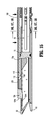
FIG. 1 is a perspective view of a release tool or assembly in accordance with the present disclosure; -
FIGS. 2 and3 are enlarged respective top and bottom perspective views of a distal end of the presently disclosed release tool or assembly; -
FIG. 4 is an enlarged cross-sectional view of the presently disclosed release tool or assembly taken along line 4-4 ofFIG. 2 ; -
FIG. 5 is a side view of the presently disclosed release tool or assembly; -
FIG. 6 is a longitudinal, cross-sectional view of the presently disclosed release tool or assembly taken along line 6-6 ofFIG. 1 ; -
FIG. 7 is a perspective view, with parts separated, of the presently disclosed release tool or assembly; -
FIG. 8 is an enlarged view of the indicated area of detail ofFIG. 7 ; -
FIG. 9 is a perspective view of an exemplary surgical stapling apparatus; -
FIG. 10 is a longitudinal, cross-sectional view of the end effector shown in a partially fired condition; -
FIG. 11 is a perspective view of a drive beam of the end effector; -
FIG. 12 is a perspective view of the presently disclosed release tool or assembly and an end effector of the surgical stapling apparatus, the end effector being shown in a partially fired condition while grasping tissue; -
FIGS. 13-18 are progressive cross-sectional views of the presently disclosed release tool or assembly being mounted on the end effector; -
FIGS. 19-20 are progressive cross-sectional views of the release tool or assembly retracting the drive beam of the end effector to a proximal position; and -
FIG. 21 is a perspective view illustrating the end effector releasing tissue after the drive beam of the end effector has been retracted to the proximal position. - Embodiments of the presently disclosed surgical devices are described in detail with reference to the drawings, in which like reference numerals designate identical or corresponding elements in each of the several views. The term "clinician", as used herein, refers to a surgeon or surgical nurse. The term "distal" refers to that portion of the device, or component thereof, which is farthest from the clinician during proper use of the device, while the term "proximal" refers to that portion of the device, or component thereof, which is closest to the clinician during proper use of the device.
- Referring initially to
FIGS. 1-8 , a release tool orassembly 100 includes arelease bar 110, anelongate body member 120, and agripping assembly 130. -
Elongate body member 120 includes abody 122 that defines alongitudinal channel 122a which extends along a longitudinal axis defined by thebody 122 between proximal and distal ends of thebody 122.Body 122 includes a first half-section 122b, a second half-section 122c, and adistal hook member 124. First and second half-sections longitudinal channel 122a and may include top and/or bottom surfaces that may be arcuate.Distal hook member 124 is disposed on the distal end of thebody 122 and includes afirst surface 124a, asecond surface 124b, and athird surface 124c. First, second, andthird surfaces first surface 124a may be substantially perpendicular to the longitudinal axis,second surface 124b may be substantially parallel to the longitudinal axis, andthird surface 124c may be disposed at a substantially acute angle relative to the longitudinal axis. -
Release bar 110 includes adrive member 112, abeam engaging hook 114 supported on a distal end ofdrive member 112, and ahandle 116 supported on a proximal end ofdrive member 112.Drive member 112 is axially movable, e.g., slidably supported, within thelongitudinal channel 122a ofelongate body member 120 so thatbeam engaging hook 114 extends from thelongitudinal channel 112a at any suitable angle, for example, perpendicularly or substantially perpendicularly.Beam engaging hook 114 includes a trailingsurface 114a, abottom surface 114b, and aleading surface 114c that may have any suitable linear or curvilinear configuration and may be disposed at any suitable angle relative to the longitudinal axis, for example, an acute, perpendicular, or substantially perpendicular angles relative to the longitudinal axis. - Handle 116 may have any suitable shape including ergonomic configurations.
- Gripping
assembly 130 is supported on the upper surface ofbody 122 ofelongate body member 120. Grippingassembly 130 includes a base 132 that pivotably supports afirst panel 134 and asecond panel 136 by a pair ofpins 138a. As seen inFig. 7 ,base 132 defines a pair ofchannels 132a that extend between proximal and distal ends ofbase 132. Eachchannel 132a may be open at the proximal end ofbase 132 to receive one ofpins 138a and closed at the distal end ofbase 132 to limit axial movement of therespective pin 138a within therespective channel 132a.First panel 134 includes a pivoting segment orspine 134c and agripping segment 134b. Pivoting segment orspine 134c defines apin passage 134a therethrough that receives one ofpins 138a. Similarly,second panel 136 includes a pivoting segment orspine 136c and agripping segment 136b. Pivoting segment orspine 136c defines apin passage 136a therethrough that receives theother pin 138a. - As shown in
FIGS. 9-11 , an electromechanical, hand-held, poweredsurgical instrument 10 includes ahandle assembly 20, ashaft assembly 30, and anend effector 40 that mechanically and electrically cooperate to manipulate tissue "T." For a detailed description of the construction and operation of exemplary electromechanical, hand-held, poweredsurgical instrument 10, reference may be made to International Application No.PCT/US2008/077249, filed September 22, 2008 (Inter. Pub. No.WO 2009/039506 ) andU.S. Patent Application Serial No. 12/622,827, filed on November 20, 2009 - Notably,
end effector 40 is selectively attachable toshaft assembly 30 and includes a first jaw member orcartridge receiving assembly 50, a second jaw member or ananvil supporting assembly 60, adrive beam assembly 70, and asled 80.Cartridge receiving assembly 50 is configured to receive acartridge 54 including a plurality of fasteners that are formed by theanvil assembly 60 upon deployment from thecartridge 54 when thesled 80 is distally axially advanced with thedrive beam assembly 70 through thecartridge 54.Cartridge receiving assembly 50 defines achannel 52 therethrough. Drivebeam assembly 70 includes a beam 72 (e.g., an I-beam, E-beam, etc.) secured to abar member 74.Beam 72 includes atop portion 72a,bottom portion 72b and ablade 72c supported between the top andbottom portions end effector 40, reference may be made toU.S. Patent Publication No. 2009/0314821, filed on August 31, 2009 , the entire contents of which are hereby incorporated by reference herein. - With reference to
FIGS. 12-15 , release tool orassembly 100 may be secured to endeffector 40 afterend effector 40 is detached fromsurgical stapling apparatus 10. Notably, release tool orassembly 100 is configured to retractdrive beam assembly 70 to a proximal position relative to cartridge receiving andanvil supporting assemblies end effector 40 to be repositioned from a closed configuration to an open configuration, as will be described in greater detail below. - Release or
tool assembly 100 is used whendrive beam assembly 70 has become stuck or jammed during a firing ofsurgical stapling apparatus 10, and whereindrive beam assembly 70 may not be retracted using the retraction/opening commands/features ofsurgical stapling apparatus 10. Withdrive beam assembly 70 so stuck, upon theend effector 40 being detached fromsurgical stapling apparatus 10, release tool orassembly 100 is secured to endeffector 40. Initially,distal hook member 124 of release tool orassembly 100 is inserted into a distal end ofchannel 52 ofcartridge receiving assembly 50, specifically distally ofbeam 72, so that release tool orassembly 100 is disposed at an acute angle relative to endeffector 40. Withrelease bar 110 in an advanced or distal position, relative pivoting movement between release tool orassembly 100 about the distal end of release tool or assembly 100 (i.e., about distal hook member 124) approximatesend effector 40 and release tool orassembly 100 so that release tool orassembly 100 is supported onend effector 40 in a parallel or substantially parallel relationship withend effector 40. In this regard,distal hook member 124 secures a distal end of release tool orassembly 100 to endeffector 40 so thatbeam engaging hook 114 is disposed distally ofbeam 72. - Referring also to
FIGS. 16-18 , upon or following approximating release tool orassembly 100 andend effector 40, first andsecond panels pins 138a relative to elongatebody member 120. In this regard, first andsecond panels end effector 40 to secure release tool orassembly 100 to endeffector 40. Upon being approximated into engagement withend effector 40, first andsecond panels assembly 100 to endeffector 40. - Turning now to
FIGS. 19-21 , withdistal hook member 124 held in position in a distal end ofchannel 52 ofcartridge receiving assembly 50, handle 116 ofrelease bar 110 is then drawn proximally with sufficient force to retractbeam engaging hook 124 so that trailingsurface 114a ofbeam engaging hook 124 contacts a leading surface oftop portion 72a ofbeam 72. Further proximal drawing ofhandle 116 retracts the stuckbeam 72 proximally to a proximal position. Release ortool assembly 100 may then be removed by pivoting first andsecond panels end effector 40 and separatingrelease assembly 100 fromend effector 40. In this regard,cartridge receiving assembly 50 andanvil supporting assembly 60 may be unapproximated to an open configuration to release any tissue entrapped betweencartridge receiving assembly 50 andanvil supporting assembly 60. - Persons skilled in the art will understand that the structures and methods specifically described herein and illustrated in the accompanying figures are non-limiting exemplary embodiments, and that the description, disclosure, and figures should be construed merely as exemplary of particular embodiments. It is to be understood, therefore, that the present disclosure is not limited to the precise embodiments described, and that various other changes and modifications may be effected by one skilled in the art without departing from the scope or spirit of the disclosure. Additionally, it is envisioned that the elements and features illustrated or described in connection with one exemplary embodiment may be combined with the elements and features of another without departing from the scope of the present disclosure, and that such modifications and variations are also intended to be included within the scope of the present disclosure. Accordingly, the subject matter of the present disclosure is not to be limited by what has been particularly shown and described.
- The invention may be described by reference to the following numbered paragraphs:-
- 1. A release tool for an end effector with a pair of jaw members and a drive beam assembly configured for axial movement through the pair of jaw members, the release tool comprising:
- an elongate body member having distal and proximal ends;
- a gripping assembly secured to the elongate body member and configured to secure the elongate body member to the end effector; and
- a release bar supported by the elongate body member and being axially movable relative to elongate body member, the release bar being configured to engage a beam of the drive beam assembly to retract the beam to a proximal position when the beam is disposed in a position distal of the proximal position.
- 2. The release tool of paragraph 1, wherein the distal end of the elongate body member includes a distal hook member.
- 3. The release tool of paragraph 1, wherein the release bar includes a beam engaging hook configured to engage the beam upon the proximal movement of the beam engaging hook so that the beam engaging hook retracts the beam to the proximal position.
- 4. The release tool of paragraph 3, wherein the release bar includes a drive member secured to the beam engaging hook, the drive member being axially movable to axially move the beam engaging hook.
- 5. The release tool of paragraph 4, wherein the release bar includes a handle, the handle being supported on a proximal end of the drive member, the beam engaging hook being supported on a distal end of the drive member.
- 6. The release tool of paragraph 1, wherein the gripping assembly includes a panel that pivots relative to the elongate body member.
- 7. The release tool of
paragraph 6, wherein the gripping assembly includes a first panel and a second panel that pivot in opposing directions relative to the elongate body member. - 8. A release tool and end effector kit, the kit comprising:
- an end effector including a pair of jaw members and a beam supported on a drive assembly configured for axial movement through the pair of jaw members; and
- a release tool that is selectively attachable to the end effector, the release tool including:
- an elongate body member;
- a gripping assembly secured to the elongate body member to secure the elongate body member to the end effector; and
- a release bar including a beam engaging hook supported by the elongate body member and being axially movable relative to the end effector when the elongate body member is secured to the end effector, the beam engaging hook of the release bar being engageable with the beam to retract the beam and drive beam assembly to a proximal position when the beam is disposed in a position distal of the proximal position.
- 9. The release tool and end effector kit of paragraph 8, wherein the pair of jaw members moves from a closed configuration to an open configuration when the beam engaging hook retracts the beam to the proximal position.
- 10. The release tool and end effector kit of paragraph 8, wherein the distal end of the elongate body member includes a hook member.
- 11. The release tool and end effector kit of paragraph 8, wherein the gripping assembly includes a panel that pivots relative to the elongate body member.
- 12. The release tool and end effector kit of paragraph 8, wherein the beam engaging hook is axially movable relative to the elongate body member.
- 13. The release tool and end effector kit of paragraph 8, wherein the pair of jaw members includes an anvil member and a cartridge member, the cartridge member being configured to receive a cartridge that retains a plurality of fasteners.
- 14. A surgical stapling kit, comprising:
- a surgical stapling apparatus including an end effector, the end effector including an anvil supporting member, a cartridge receiving member, and a beam supported on a drive beam assembly that moves axially through the anvil supporting member and the cartridge receiving member; and
- a release tool that is selectively attachable to the end effector, the release tool including:
- an elongate body member;
- a pair of panels secured to the elongate body member to secure the release tool to the end effector; and
- a release bar including a beam engaging member, the release bar being supported by the elongate body member and being axially movable relative to the end effector when the release tool is secured to the end effector, the beam engaging member of the release bar being engageable with the beam to retract the beam and the drive beam assembly to a proximal position when the beam is disposed in a position distal of the proximal position.
- 15. The surgical stapling kit of
paragraph 14, wherein the anvil supporting member and the cartridge receiving member of the end effector move from a closed configuration to an open configuration when the beam engaging member of the release tool retracts the beam and the drive beam assembly to the proximal position. - 16. The surgical stapling kit of
paragraph 14, wherein the elongate body member of the release tool includes a distal hook member. - 17. The surgical stapling kit of paragraph 16, wherein the cartridge receiving member of the end effector defines a channel through a top surface thereof, wherein a top portion of the beam axially translates through the channel upon the axial movement of the beam, the distal hook member of the elongate body member being positionable within the channel.
- 18. The surgical stapling kit of paragraph 17, wherein a proximal surface of the beam engaging member of the release bar contacts a distal surface of the top portion of the beam when the beam engaging member and the beam are engaged.
- 19. The surgical stapling kit of
paragraph 14, wherein the panels pivot relative to the elongate body member to secure the release tool to the end effector. - 20. The surgical stapling kit of
paragraph 14, wherein the beam engaging member of the release bar is axially movable relative to the elongate body member.
Claims (15)
- A release tool for an end effector with a pair of jaw members and a drive beam assembly configured for axial movement through the pair of jaw members, the release tool comprising:an elongate body member having distal and proximal ends;a gripping assembly secured to the elongate body member and configured to secure the elongate body member to the end effector; anda release bar supported by the elongate body member and being axially movable relative to elongate body member, the release bar being configured to engage a beam of the drive beam assembly to retract the beam to a proximal position when the beam is disposed in a position distal of the proximal position.
- The release tool of claim 1, wherein the distal end of the elongate body member includes a distal hook member and/or wherein the release bar includes a beam engaging hook configured to engage the beam upon the proximal movement of the beam engaging hook so that the beam engaging hook retracts the beam to the proximal position.
- The release tool of claim 2, wherein the release bar includes a drive member secured to the beam engaging hook, the drive member being axially movable to axially move the beam engaging hook, and/or wherein the release bar includes a handle, the handle being supported on a proximal end of the drive member, the beam engaging hook being supported on a distal end of the drive member.
- The release tool of any preceding claim, wherein the gripping assembly includes a panel that pivots relative to the elongate body member, preferably wherein the gripping assembly includes a first panel and a second panel that pivot in opposing directions relative to the elongate body member.
- A release tool and end effector kit, the kit comprising:an end effector including a pair of jaw members and a beam supported on a drive assembly configured for axial movement through the pair of jaw members; anda release tool that is selectively attachable to the end effector, the release tool including:an elongate body member;a gripping assembly secured to the elongate body member to secure the elongate body member to the end effector; anda release bar including a beam engaging hook supported by the elongate body member and being axially movable relative to the end effector when the elongate body member is secured to the end effector, the beam engaging hook of the release bar being engageable with the beam to retract the beam and drive beam assembly to a proximal position when the beam is disposed in a position distal of the proximal position.
- The release tool and end effector kit of claim 5, wherein the pair of jaw members moves from a closed configuration to an open configuration when the beam engaging hook retracts the beam to the proximal position, and/or wherein the distal end of the elongate body member includes a hook member.
- The release tool and end effector kit of claim 5 or claim 6, wherein the gripping assembly includes a panel that pivots relative to the elongate body member.
- The release tool and end effector kit of any of claims 5 to 7, wherein the beam engaging hook is axially movable relative to the elongate body member.
- The release tool and end effector kit of any of claims 5 to 8, wherein the pair of jaw members includes an anvil member and a cartridge member, the cartridge member being configured to receive a cartridge that retains a plurality of fasteners.
- A surgical stapling kit, comprising:a surgical stapling apparatus including an end effector, the end effector including an anvil supporting member, a cartridge receiving member, and a beam supported on a drive beam assembly that moves axially through the anvil supporting member and the cartridge receiving member; and
a release tool that is selectively attachable to the end effector, the release tool including:an elongate body member;a pair of panels secured to the elongate body member to secure the release tool to the end effector; anda release bar including a beam engaging member, the release bar being supported by the elongate body member and being axially movable relative to the end effector when the release tool is secured to the end effector, the beam engaging member of the release bar being engageable with the beam to retract the beam and the drive beam assembly to a proximal position when the beam is disposed in a position distal of the proximal position. - The surgical stapling kit of claim 10, wherein the anvil supporting member and the cartridge receiving member of the end effector move from a closed configuration to an open configuration when the beam engaging member of the release tool retracts the beam and the drive beam assembly to the proximal position.
- The surgical stapling kit of claim 10 or claim 11, wherein the elongate body member of the release tool includes a distal hook member.
- The surgical stapling kit of any of claims 10 to 12, wherein the cartridge receiving member of the end effector defines a channel through a top surface thereof, wherein a top portion of the beam axially translates through the channel upon the axial movement of the beam, the distal hook member of the elongate body member being positionable within the channel.
- The surgical stapling kit of any of claims 10 to 13, wherein a proximal surface of the beam engaging member of the release bar contacts a distal surface of the top portion of the beam when the beam engaging member and the beam are engaged.
- The surgical stapling kit of any of claims 10 to 14, wherein the panels pivot relative to the elongate body member to secure the release tool to the end effector, and/or wherein the beam engaging member of the release bar is axially movable relative to the elongate body member.
Applications Claiming Priority (2)
| Application Number | Priority Date | Filing Date | Title |
|---|---|---|---|
| US201361754170P | 2013-01-18 | 2013-01-18 | |
| US14/143,520 US9615825B2 (en) | 2013-01-18 | 2013-12-30 | Release tool for an end effector of a surgical stapling apparatus |
Publications (2)
| Publication Number | Publication Date |
|---|---|
| EP2756810A2 true EP2756810A2 (en) | 2014-07-23 |
| EP2756810A3 EP2756810A3 (en) | 2016-11-30 |
Family
ID=49955985
Family Applications (1)
| Application Number | Title | Priority Date | Filing Date |
|---|---|---|---|
| EP14151671.6A Withdrawn EP2756810A3 (en) | 2013-01-18 | 2014-01-17 | Release tool for an end effector of surgical stapling apparatus |
Country Status (4)
| Country | Link |
|---|---|
| US (1) | US9615825B2 (en) |
| EP (1) | EP2756810A3 (en) |
| AU (1) | AU2014200104A1 (en) |
| CA (1) | CA2839888A1 (en) |
Families Citing this family (129)
| Publication number | Priority date | Publication date | Assignee | Title |
|---|---|---|---|---|
| US9033204B2 (en) | 2011-03-14 | 2015-05-19 | Ethicon Endo-Surgery, Inc. | Circular stapling devices with tissue-puncturing anvil features |
| AU2013403917A1 (en) | 2013-11-04 | 2016-04-28 | Covidien Lp | Surgical fastener applying apparatus |
| EP3065648A1 (en) | 2013-11-04 | 2016-09-14 | Covidien LP | Surgical fastener applying apparatus |
| CN110063762B (en) | 2013-11-04 | 2022-04-15 | 柯惠Lp公司 | Surgical fastener applying apparatus |
| WO2015174985A1 (en) | 2014-05-15 | 2015-11-19 | Lp Covidien | Surgical fastener applying apparatus |
| US10039545B2 (en) | 2015-02-23 | 2018-08-07 | Covidien Lp | Double fire stapling |
| US10285698B2 (en) | 2015-02-26 | 2019-05-14 | Covidien Lp | Surgical apparatus |
| US10085749B2 (en) | 2015-02-26 | 2018-10-02 | Covidien Lp | Surgical apparatus with conductor strain relief |
| US10463368B2 (en) | 2015-04-10 | 2019-11-05 | Covidien Lp | Endoscopic stapler |
| US10349941B2 (en) | 2015-05-27 | 2019-07-16 | Covidien Lp | Multi-fire lead screw stapling device |
| US10172615B2 (en) | 2015-05-27 | 2019-01-08 | Covidien Lp | Multi-fire push rod stapling device |
| US10064622B2 (en) | 2015-07-29 | 2018-09-04 | Covidien Lp | Surgical stapling loading unit with stroke counter and lockout |
| US10045782B2 (en) | 2015-07-30 | 2018-08-14 | Covidien Lp | Surgical stapling loading unit with stroke counter and lockout |
| US10213204B2 (en) | 2015-10-02 | 2019-02-26 | Covidien Lp | Micro surgical instrument and loading unit for use therewith |
| US10772632B2 (en) | 2015-10-28 | 2020-09-15 | Covidien Lp | Surgical stapling device with triple leg staples |
| US10595864B2 (en) | 2015-11-24 | 2020-03-24 | Covidien Lp | Adapter assembly for interconnecting electromechanical surgical devices and surgical loading units, and surgical systems thereof |
| US10111660B2 (en) | 2015-12-03 | 2018-10-30 | Covidien Lp | Surgical stapler flexible distal tip |
| US10966717B2 (en) | 2016-01-07 | 2021-04-06 | Covidien Lp | Surgical fastener apparatus |
| US10660623B2 (en) | 2016-01-15 | 2020-05-26 | Covidien Lp | Centering mechanism for articulation joint |
| US10349937B2 (en) | 2016-02-10 | 2019-07-16 | Covidien Lp | Surgical stapler with articulation locking mechanism |
| US10420559B2 (en) | 2016-02-11 | 2019-09-24 | Covidien Lp | Surgical stapler with small diameter endoscopic portion |
| JP6938533B2 (en) * | 2016-04-01 | 2021-09-22 | エシコン エルエルシーEthicon LLC | Surgical staple fastening system |
| US10376263B2 (en) | 2016-04-01 | 2019-08-13 | Ethicon Llc | Anvil modification members for surgical staplers |
| US11284890B2 (en) | 2016-04-01 | 2022-03-29 | Cilag Gmbh International | Circular stapling system comprising an incisable tissue support |
| US10675021B2 (en) * | 2016-04-01 | 2020-06-09 | Ethicon Llc | Circular stapling system comprising rotary firing system |
| US10307159B2 (en) | 2016-04-01 | 2019-06-04 | Ethicon Llc | Surgical instrument handle assembly with reconfigurable grip portion |
| US10561419B2 (en) | 2016-05-04 | 2020-02-18 | Covidien Lp | Powered end effector assembly with pivotable channel |
| US11065022B2 (en) | 2016-05-17 | 2021-07-20 | Covidien Lp | Cutting member for a surgical instrument |
| US10631857B2 (en) | 2016-11-04 | 2020-04-28 | Covidien Lp | Loading unit for surgical instruments with low profile pushers |
| US11642126B2 (en) | 2016-11-04 | 2023-05-09 | Covidien Lp | Surgical stapling apparatus with tissue pockets |
| US10492784B2 (en) | 2016-11-08 | 2019-12-03 | Covidien Lp | Surgical tool assembly with compact firing assembly |
| US10463371B2 (en) | 2016-11-29 | 2019-11-05 | Covidien Lp | Reload assembly with spent reload indicator |
| US10709901B2 (en) | 2017-01-05 | 2020-07-14 | Covidien Lp | Implantable fasteners, applicators, and methods for brachytherapy |
| US10952767B2 (en) | 2017-02-06 | 2021-03-23 | Covidien Lp | Connector clip for securing an introducer to a surgical fastener applying apparatus |
| US20180235618A1 (en) | 2017-02-22 | 2018-08-23 | Covidien Lp | Loading unit for surgical instruments with low profile pushers |
| US11350915B2 (en) | 2017-02-23 | 2022-06-07 | Covidien Lp | Surgical stapler with small diameter endoscopic portion |
| US10849621B2 (en) | 2017-02-23 | 2020-12-01 | Covidien Lp | Surgical stapler with small diameter endoscopic portion |
| US10299790B2 (en) | 2017-03-03 | 2019-05-28 | Covidien Lp | Adapter with centering mechanism for articulation joint |
| US10660641B2 (en) | 2017-03-16 | 2020-05-26 | Covidien Lp | Adapter with centering mechanism for articulation joint |
| US10603035B2 (en) | 2017-05-02 | 2020-03-31 | Covidien Lp | Surgical loading unit including an articulating end effector |
| US11324502B2 (en) | 2017-05-02 | 2022-05-10 | Covidien Lp | Surgical loading unit including an articulating end effector |
| US10524784B2 (en) | 2017-05-05 | 2020-01-07 | Covidien Lp | Surgical staples with expandable backspan |
| US10390826B2 (en) | 2017-05-08 | 2019-08-27 | Covidien Lp | Surgical stapling device with elongated tool assembly and methods of use |
| US10420551B2 (en) | 2017-05-30 | 2019-09-24 | Covidien Lp | Authentication and information system for reusable surgical instruments |
| US10478185B2 (en) | 2017-06-02 | 2019-11-19 | Covidien Lp | Tool assembly with minimal dead space |
| US10624636B2 (en) | 2017-08-23 | 2020-04-21 | Covidien Lp | Surgical stapling device with floating staple cartridge |
| US10806452B2 (en) | 2017-08-24 | 2020-10-20 | Covidien Lp | Loading unit for a surgical stapling instrument |
| US10925603B2 (en) | 2017-11-14 | 2021-02-23 | Covidien Lp | Reload with articulation stabilization system |
| US10863987B2 (en) | 2017-11-16 | 2020-12-15 | Covidien Lp | Surgical instrument with imaging device |
| US10945732B2 (en) | 2018-01-17 | 2021-03-16 | Covidien Lp | Surgical stapler with self-returning assembly |
| US11369371B2 (en) | 2018-03-02 | 2022-06-28 | Covidien Lp | Surgical stapling instrument |
| US10849622B2 (en) | 2018-06-21 | 2020-12-01 | Covidien Lp | Articulated stapling with fire lock |
| US10736631B2 (en) | 2018-08-07 | 2020-08-11 | Covidien Lp | End effector with staple cartridge ejector |
| US10849620B2 (en) | 2018-09-14 | 2020-12-01 | Covidien Lp | Connector mechanisms for surgical stapling instruments |
| US11510669B2 (en) | 2020-09-29 | 2022-11-29 | Covidien Lp | Hand-held surgical instruments |
| US11090051B2 (en) | 2018-10-23 | 2021-08-17 | Covidien Lp | Surgical stapling device with floating staple cartridge |
| US11197673B2 (en) | 2018-10-30 | 2021-12-14 | Covidien Lp | Surgical stapling instruments and end effector assemblies thereof |
| CN111134752A (en) * | 2018-11-02 | 2020-05-12 | 逸思(苏州)医疗科技有限公司 | Safety mechanism ensuring single use of instrument |
| US10912563B2 (en) | 2019-01-02 | 2021-02-09 | Covidien Lp | Stapling device including tool assembly stabilizing member |
| US11344297B2 (en) | 2019-02-28 | 2022-05-31 | Covidien Lp | Surgical stapling device with independently movable jaws |
| US11259808B2 (en) | 2019-03-13 | 2022-03-01 | Covidien Lp | Tool assemblies with a gap locking member |
| US11284892B2 (en) | 2019-04-01 | 2022-03-29 | Covidien Lp | Loading unit and adapter with modified coupling assembly |
| US11284893B2 (en) | 2019-04-02 | 2022-03-29 | Covidien Lp | Stapling device with articulating tool assembly |
| US11241228B2 (en) | 2019-04-05 | 2022-02-08 | Covidien Lp | Surgical instrument including an adapter assembly and an articulating surgical loading unit |
| US11224424B2 (en) | 2019-08-02 | 2022-01-18 | Covidien Lp | Linear stapling device with vertically movable knife |
| US11406385B2 (en) | 2019-10-11 | 2022-08-09 | Covidien Lp | Stapling device with a gap locking member |
| US11123068B2 (en) | 2019-11-08 | 2021-09-21 | Covidien Lp | Surgical staple cartridge |
| US11707274B2 (en) | 2019-12-06 | 2023-07-25 | Covidien Lp | Articulating mechanism for surgical instrument |
| US11109862B2 (en) | 2019-12-12 | 2021-09-07 | Covidien Lp | Surgical stapling device with flexible shaft |
| US11737747B2 (en) | 2019-12-17 | 2023-08-29 | Covidien Lp | Hand-held surgical instruments |
| US11278282B2 (en) | 2020-01-31 | 2022-03-22 | Covidien Lp | Stapling device with selective cutting |
| US11452524B2 (en) | 2020-01-31 | 2022-09-27 | Covidien Lp | Surgical stapling device with lockout |
| CN115135251A (en) | 2020-02-14 | 2022-09-30 | 柯惠有限合伙公司 | Cartridge holder for surgical staples having ridges on the outer peripheral wall for gripping tissue |
| US11344301B2 (en) | 2020-03-02 | 2022-05-31 | Covidien Lp | Surgical stapling device with replaceable reload assembly |
| US11344302B2 (en) | 2020-03-05 | 2022-05-31 | Covidien Lp | Articulation mechanism for surgical stapling device |
| US11707278B2 (en) | 2020-03-06 | 2023-07-25 | Covidien Lp | Surgical stapler tool assembly to minimize bleeding |
| US11246593B2 (en) | 2020-03-06 | 2022-02-15 | Covidien Lp | Staple cartridge |
| US11317911B2 (en) | 2020-03-10 | 2022-05-03 | Covidien Lp | Tool assembly with replaceable cartridge assembly |
| US11357505B2 (en) | 2020-03-10 | 2022-06-14 | Covidien Lp | Surgical stapling apparatus with firing lockout mechanism |
| US11406383B2 (en) | 2020-03-17 | 2022-08-09 | Covidien Lp | Fire assisted powered EGIA handle |
| US11331098B2 (en) | 2020-04-01 | 2022-05-17 | Covidien Lp | Sled detection device |
| US11426159B2 (en) | 2020-04-01 | 2022-08-30 | Covidien Lp | Sled detection device |
| US11504117B2 (en) | 2020-04-02 | 2022-11-22 | Covidien Lp | Hand-held surgical instruments |
| US11937794B2 (en) | 2020-05-11 | 2024-03-26 | Covidien Lp | Powered handle assembly for surgical devices |
| US11406387B2 (en) | 2020-05-12 | 2022-08-09 | Covidien Lp | Surgical stapling device with replaceable staple cartridge |
| US11191537B1 (en) | 2020-05-12 | 2021-12-07 | Covidien Lp | Stapling device with continuously parallel jaws |
| US11534167B2 (en) | 2020-05-28 | 2022-12-27 | Covidien Lp | Electrotaxis-conducive stapling |
| US11191538B1 (en) | 2020-06-08 | 2021-12-07 | Covidien Lp | Surgical stapling device with parallel jaw closure |
| US11844517B2 (en) | 2020-06-25 | 2023-12-19 | Covidien Lp | Linear stapling device with continuously parallel jaws |
| US11324500B2 (en) | 2020-06-30 | 2022-05-10 | Covidien Lp | Surgical stapling device |
| US11446028B2 (en) | 2020-07-09 | 2022-09-20 | Covidien Lp | Tool assembly with pivotable clamping beam |
| US11517305B2 (en) | 2020-07-09 | 2022-12-06 | Covidien Lp | Contoured staple pusher |
| US11266402B2 (en) | 2020-07-30 | 2022-03-08 | Covidien Lp | Sensing curved tip for surgical stapling instruments |
| US11439392B2 (en) | 2020-08-03 | 2022-09-13 | Covidien Lp | Surgical stapling device and fastener for pathological exam |
| US11395654B2 (en) | 2020-08-07 | 2022-07-26 | Covidien Lp | Surgical stapling device with articulation braking assembly |
| US11602342B2 (en) | 2020-08-27 | 2023-03-14 | Covidien Lp | Surgical stapling device with laser probe |
| US11678878B2 (en) | 2020-09-16 | 2023-06-20 | Covidien Lp | Articulation mechanism for surgical stapling device |
| US11660092B2 (en) | 2020-09-29 | 2023-05-30 | Covidien Lp | Adapter for securing loading units to handle assemblies of surgical stapling instruments |
| US11406384B2 (en) | 2020-10-05 | 2022-08-09 | Covidien Lp | Stapling device with drive assembly stop member |
| US11576674B2 (en) | 2020-10-06 | 2023-02-14 | Covidien Lp | Surgical stapling device with articulation lock assembly |
| US11890007B2 (en) | 2020-11-18 | 2024-02-06 | Covidien Lp | Stapling device with flex cable and tensioning mechanism |
| US11737774B2 (en) | 2020-12-04 | 2023-08-29 | Covidien Lp | Surgical instrument with articulation assembly |
| US11819200B2 (en) | 2020-12-15 | 2023-11-21 | Covidien Lp | Surgical instrument with articulation assembly |
| US11553914B2 (en) | 2020-12-22 | 2023-01-17 | Covidien Lp | Surgical stapling device with parallel jaw closure |
| US11759206B2 (en) | 2021-01-05 | 2023-09-19 | Covidien Lp | Surgical stapling device with firing lockout mechanism |
| US11744582B2 (en) | 2021-01-05 | 2023-09-05 | Covidien Lp | Surgical stapling device with firing lockout mechanism |
| US11759207B2 (en) | 2021-01-27 | 2023-09-19 | Covidien Lp | Surgical stapling apparatus with adjustable height clamping member |
| US11517313B2 (en) | 2021-01-27 | 2022-12-06 | Covidien Lp | Surgical stapling device with laminated drive member |
| US11717300B2 (en) | 2021-03-11 | 2023-08-08 | Covidien Lp | Surgical stapling apparatus with integrated visualization |
| US11497495B2 (en) | 2021-03-31 | 2022-11-15 | Covidien Lp | Continuous stapler strip for use with a surgical stapling device |
| US11666330B2 (en) | 2021-04-05 | 2023-06-06 | Covidien Lp | Surgical stapling device with lockout mechanism |
| US11576670B2 (en) | 2021-05-06 | 2023-02-14 | Covidien Lp | Surgical stapling device with optimized drive assembly |
| US11812956B2 (en) | 2021-05-18 | 2023-11-14 | Covidien Lp | Dual firing radial stapling device |
| US11696755B2 (en) | 2021-05-19 | 2023-07-11 | Covidien Lp | Surgical stapling device with reload assembly removal lockout |
| US11510673B1 (en) | 2021-05-25 | 2022-11-29 | Covidien Lp | Powered stapling device with manual retraction |
| US11771423B2 (en) | 2021-05-25 | 2023-10-03 | Covidien Lp | Powered stapling device with manual retraction |
| US11701119B2 (en) | 2021-05-26 | 2023-07-18 | Covidien Lp | Powered stapling device with rack release |
| US11576675B2 (en) | 2021-06-07 | 2023-02-14 | Covidien Lp | Staple cartridge with knife |
| US11707275B2 (en) | 2021-06-29 | 2023-07-25 | Covidien Lp | Asymmetrical surgical stapling device |
| US11617579B2 (en) | 2021-06-29 | 2023-04-04 | Covidien Lp | Ultra low profile surgical stapling instrument for tissue resections |
| US11602344B2 (en) | 2021-06-30 | 2023-03-14 | Covidien Lp | Surgical stapling apparatus with firing lockout assembly |
| US11540831B1 (en) | 2021-08-12 | 2023-01-03 | Covidien Lp | Staple cartridge with actuation sled detection |
| US11779334B2 (en) | 2021-08-19 | 2023-10-10 | Covidien Lp | Surgical stapling device including a manual retraction assembly |
| US11576671B1 (en) | 2021-08-20 | 2023-02-14 | Covidien Lp | Small diameter linear surgical stapling apparatus |
| US11707277B2 (en) | 2021-08-20 | 2023-07-25 | Covidien Lp | Articulating surgical stapling apparatus with pivotable knife bar guide assembly |
| US11864761B2 (en) | 2021-09-14 | 2024-01-09 | Covidien Lp | Surgical instrument with illumination mechanism |
| US11653922B2 (en) | 2021-09-29 | 2023-05-23 | Covidien Lp | Surgical stapling device with firing lockout mechanism |
| US11660094B2 (en) | 2021-09-29 | 2023-05-30 | Covidien Lp | Surgical fastening instrument with two-part surgical fasteners |
| US11849949B2 (en) | 2021-09-30 | 2023-12-26 | Covidien Lp | Surgical stapling device with firing lockout member |
Citations (2)
| Publication number | Priority date | Publication date | Assignee | Title |
|---|---|---|---|---|
| WO2009039506A1 (en) | 2007-09-21 | 2009-03-26 | Power Medical Interventions, Inc. | Surgical device |
| US20090314821A1 (en) | 2002-10-04 | 2009-12-24 | Tyco Healthcare Group Lp | Tool Assembly For A Surgical Stapling Device |
Family Cites Families (9)
| Publication number | Priority date | Publication date | Assignee | Title |
|---|---|---|---|---|
| US6021854A (en) * | 1998-04-24 | 2000-02-08 | Scarola; Ralph | Adapter handle for power tool |
| US10588629B2 (en) | 2009-11-20 | 2020-03-17 | Covidien Lp | Surgical console and hand-held surgical device |
| US7568605B2 (en) * | 2006-03-22 | 2009-08-04 | Ethicon Endo-Surgery, Inc. | Surgical stapler shaft cover |
| US7866527B2 (en) * | 2008-02-14 | 2011-01-11 | Ethicon Endo-Surgery, Inc. | Surgical stapling apparatus with interlockable firing system |
| US8608045B2 (en) * | 2008-10-10 | 2013-12-17 | Ethicon Endo-Sugery, Inc. | Powered surgical cutting and stapling apparatus with manually retractable firing system |
| US8608046B2 (en) | 2010-01-07 | 2013-12-17 | Ethicon Endo-Surgery, Inc. | Test device for a surgical tool |
| EP2523607A1 (en) | 2010-01-14 | 2012-11-21 | Sunton Wongsiri | The surgical visual field enhancer apparatus and its method of use |
| US20130214024A1 (en) * | 2010-04-08 | 2013-08-22 | Hidehisa Thomas Takei | Introducer System and Assembly for Surgical Staplers |
| US8397972B2 (en) | 2011-03-18 | 2013-03-19 | Covidien Lp | Shipping wedge with lockout |
-
2013
- 2013-12-30 US US14/143,520 patent/US9615825B2/en not_active Expired - Fee Related
-
2014
- 2014-01-09 AU AU2014200104A patent/AU2014200104A1/en not_active Abandoned
- 2014-01-17 EP EP14151671.6A patent/EP2756810A3/en not_active Withdrawn
- 2014-01-17 CA CA2839888A patent/CA2839888A1/en not_active Abandoned
Patent Citations (2)
| Publication number | Priority date | Publication date | Assignee | Title |
|---|---|---|---|---|
| US20090314821A1 (en) | 2002-10-04 | 2009-12-24 | Tyco Healthcare Group Lp | Tool Assembly For A Surgical Stapling Device |
| WO2009039506A1 (en) | 2007-09-21 | 2009-03-26 | Power Medical Interventions, Inc. | Surgical device |
Also Published As
| Publication number | Publication date |
|---|---|
| EP2756810A3 (en) | 2016-11-30 |
| CA2839888A1 (en) | 2014-07-18 |
| US20140203062A1 (en) | 2014-07-24 |
| US9615825B2 (en) | 2017-04-11 |
| AU2014200104A1 (en) | 2014-08-07 |
Similar Documents
| Publication | Publication Date | Title |
|---|---|---|
| EP2756810A2 (en) | Release tool for an end effector of surgical stapling apparatus | |
| EP3205288B1 (en) | Flexible circular stapler | |
| JP6938532B2 (en) | Circular staple fastening system with incisable tissue support | |
| EP2942019B1 (en) | Ejecting assembly for a surgical stapler | |
| US9386985B2 (en) | Surgical cutting instrument | |
| EP3009080B1 (en) | Staple cartridge | |
| EP2682061B1 (en) | T-slot tilt anvil for circular stapling instrument | |
| US9345482B2 (en) | Sliding sleeve for circular stapling instrument reloads | |
| EP3257451A1 (en) | Tool assembly for leak resistant tissue dissection | |
| EP3120783A1 (en) | Small diameter cartridge design for a surgical stapling instrument | |
| CN112294382A (en) | Knife locking wedge | |
| EP3318199A1 (en) | Surgical tool assembly with compact firing assembly | |
| EP2529673A2 (en) | Replaceable staple cartridge | |
| EP2604193B1 (en) | Surgical instrument including firing indicator | |
| EP2756809A1 (en) | Surgical instrument and cartridge members for use therewith | |
| EP3005956A1 (en) | Staple cartridge with shipping wedge | |
| JP2015128582A (en) | Shipping member for loading unit | |
| EP3922192A2 (en) | Alignment pin assembly for surgical stapler | |
| JP6957500B2 (en) | Circular staple fastening system including load control | |
| CN214259400U (en) | Circular stapling device and housing assembly | |
| EP1813197A2 (en) | Surgical stapling apparatus with locking mechanism | |
| EP3871616A1 (en) | Staple reload assembly with releasable knife | |
| EP3847977A1 (en) | Cut optimization for excessive tissue conditions | |
| JP7010839B2 (en) | Staple cartridge with non-invasive features | |
| EP3957254A2 (en) | Surgical stapling device with sleeve to improve grasping capability |
Legal Events
| Date | Code | Title | Description |
|---|---|---|---|
| PUAI | Public reference made under article 153(3) epc to a published international application that has entered the european phase |
Free format text: ORIGINAL CODE: 0009012 |
|
| 17P | Request for examination filed |
Effective date: 20140117 |
|
| AK | Designated contracting states |
Kind code of ref document: A2 Designated state(s): AL AT BE BG CH CY CZ DE DK EE ES FI FR GB GR HR HU IE IS IT LI LT LU LV MC MK MT NL NO PL PT RO RS SE SI SK SM TR |
|
| AX | Request for extension of the european patent |
Extension state: BA ME |
|
| PUAL | Search report despatched |
Free format text: ORIGINAL CODE: 0009013 |
|
| AK | Designated contracting states |
Kind code of ref document: A3 Designated state(s): AL AT BE BG CH CY CZ DE DK EE ES FI FR GB GR HR HU IE IS IT LI LT LU LV MC MK MT NL NO PL PT RO RS SE SI SK SM TR |
|
| AX | Request for extension of the european patent |
Extension state: BA ME |
|
| RIC1 | Information provided on ipc code assigned before grant |
Ipc: A61B 17/072 20060101AFI20161027BHEP |
|
| STAA | Information on the status of an ep patent application or granted ep patent |
Free format text: STATUS: THE APPLICATION IS DEEMED TO BE WITHDRAWN |
|
| 18D | Application deemed to be withdrawn |
Effective date: 20170531 |