EP2756535B1 - Method for evaluating the sealing of a bipolar structure for an electrochemical generator - Google Patents
Method for evaluating the sealing of a bipolar structure for an electrochemical generator Download PDFInfo
- Publication number
- EP2756535B1 EP2756535B1 EP12756764.2A EP12756764A EP2756535B1 EP 2756535 B1 EP2756535 B1 EP 2756535B1 EP 12756764 A EP12756764 A EP 12756764A EP 2756535 B1 EP2756535 B1 EP 2756535B1
- Authority
- EP
- European Patent Office
- Prior art keywords
- bipolar
- bipolar structure
- compartment
- fluid
- electrode
- Prior art date
- Legal status (The legal status is an assumption and is not a legal conclusion. Google has not performed a legal analysis and makes no representation as to the accuracy of the status listed.)
- Active
Links
- 238000000034 method Methods 0.000 title claims description 13
- 238000007789 sealing Methods 0.000 title claims description 8
- 239000000758 substrate Substances 0.000 claims description 19
- 239000012530 fluid Substances 0.000 claims description 12
- 229910001416 lithium ion Inorganic materials 0.000 claims description 5
- HBBGRARXTFLTSG-UHFFFAOYSA-N Lithium ion Chemical compound [Li+] HBBGRARXTFLTSG-UHFFFAOYSA-N 0.000 claims description 4
- 238000003780 insertion Methods 0.000 claims description 4
- 230000037431 insertion Effects 0.000 claims description 4
- 238000005259 measurement Methods 0.000 claims description 4
- 239000003990 capacitor Substances 0.000 claims description 2
- XAGFODPZIPBFFR-UHFFFAOYSA-N aluminium Chemical compound [Al] XAGFODPZIPBFFR-UHFFFAOYSA-N 0.000 description 10
- 238000012360 testing method Methods 0.000 description 10
- 229910052782 aluminium Inorganic materials 0.000 description 9
- 238000003490 calendering Methods 0.000 description 7
- 229910052744 lithium Inorganic materials 0.000 description 7
- WHXSMMKQMYFTQS-UHFFFAOYSA-N Lithium Chemical compound [Li] WHXSMMKQMYFTQS-UHFFFAOYSA-N 0.000 description 6
- 238000009434 installation Methods 0.000 description 5
- 239000003792 electrolyte Substances 0.000 description 4
- 230000035699 permeability Effects 0.000 description 4
- 239000011149 active material Substances 0.000 description 3
- 239000011230 binding agent Substances 0.000 description 3
- 239000011532 electronic conductor Substances 0.000 description 3
- 150000002500 ions Chemical class 0.000 description 3
- 239000000463 material Substances 0.000 description 3
- 229910052751 metal Inorganic materials 0.000 description 3
- 239000002184 metal Substances 0.000 description 3
- 239000000203 mixture Substances 0.000 description 3
- 229920000642 polymer Polymers 0.000 description 3
- 238000010998 test method Methods 0.000 description 3
- OKTJSMMVPCPJKN-UHFFFAOYSA-N Carbon Chemical compound [C] OKTJSMMVPCPJKN-UHFFFAOYSA-N 0.000 description 2
- RYGMFSIKBFXOCR-UHFFFAOYSA-N Copper Chemical compound [Cu] RYGMFSIKBFXOCR-UHFFFAOYSA-N 0.000 description 2
- 229910005446 Li1.04Mn1.96O4 Inorganic materials 0.000 description 2
- PXHVJJICTQNCMI-UHFFFAOYSA-N Nickel Chemical compound [Ni] PXHVJJICTQNCMI-UHFFFAOYSA-N 0.000 description 2
- ATJFFYVFTNAWJD-UHFFFAOYSA-N Tin Chemical compound [Sn] ATJFFYVFTNAWJD-UHFFFAOYSA-N 0.000 description 2
- 230000008901 benefit Effects 0.000 description 2
- 229910052799 carbon Inorganic materials 0.000 description 2
- 229910052802 copper Inorganic materials 0.000 description 2
- 239000010949 copper Substances 0.000 description 2
- 230000001351 cycling effect Effects 0.000 description 2
- 230000002950 deficient Effects 0.000 description 2
- -1 lithium cations Chemical class 0.000 description 2
- 238000004519 manufacturing process Methods 0.000 description 2
- 150000002739 metals Chemical class 0.000 description 2
- 229920001343 polytetrafluoroethylene Polymers 0.000 description 2
- 239000004810 polytetrafluoroethylene Substances 0.000 description 2
- 229920002981 polyvinylidene fluoride Polymers 0.000 description 2
- 238000003825 pressing Methods 0.000 description 2
- 229910052710 silicon Inorganic materials 0.000 description 2
- 239000010703 silicon Substances 0.000 description 2
- 229910032387 LiCoO2 Inorganic materials 0.000 description 1
- 229910010707 LiFePO 4 Inorganic materials 0.000 description 1
- 229910052493 LiFePO4 Inorganic materials 0.000 description 1
- 229910002992 LiNi0.33Mn0.33Co0.33O2 Inorganic materials 0.000 description 1
- 229910002097 Lithium manganese(III,IV) oxide Inorganic materials 0.000 description 1
- SECXISVLQFMRJM-UHFFFAOYSA-N N-Methylpyrrolidone Chemical compound CN1CCCC1=O SECXISVLQFMRJM-UHFFFAOYSA-N 0.000 description 1
- 239000002033 PVDF binder Substances 0.000 description 1
- 229920002125 Sokalan® Polymers 0.000 description 1
- 229910010413 TiO 2 Inorganic materials 0.000 description 1
- 230000002159 abnormal effect Effects 0.000 description 1
- 230000004913 activation Effects 0.000 description 1
- 230000004075 alteration Effects 0.000 description 1
- 150000001768 cations Chemical class 0.000 description 1
- 238000006243 chemical reaction Methods 0.000 description 1
- 239000011248 coating agent Substances 0.000 description 1
- 238000000576 coating method Methods 0.000 description 1
- 239000002131 composite material Substances 0.000 description 1
- 150000001875 compounds Chemical class 0.000 description 1
- 229920001940 conductive polymer Polymers 0.000 description 1
- 230000007797 corrosion Effects 0.000 description 1
- 238000005260 corrosion Methods 0.000 description 1
- 238000009831 deintercalation Methods 0.000 description 1
- 238000001514 detection method Methods 0.000 description 1
- 230000006866 deterioration Effects 0.000 description 1
- 238000011161 development Methods 0.000 description 1
- 238000009792 diffusion process Methods 0.000 description 1
- 230000000694 effects Effects 0.000 description 1
- 238000003487 electrochemical reaction Methods 0.000 description 1
- 239000007772 electrode material Substances 0.000 description 1
- 238000011156 evaluation Methods 0.000 description 1
- 230000008020 evaporation Effects 0.000 description 1
- 238000001704 evaporation Methods 0.000 description 1
- 238000010438 heat treatment Methods 0.000 description 1
- 238000005304 joining Methods 0.000 description 1
- 239000011244 liquid electrolyte Substances 0.000 description 1
- 238000012986 modification Methods 0.000 description 1
- 230000004048 modification Effects 0.000 description 1
- 239000007773 negative electrode material Substances 0.000 description 1
- 229910052759 nickel Inorganic materials 0.000 description 1
- 230000002093 peripheral effect Effects 0.000 description 1
- 239000004584 polyacrylic acid Substances 0.000 description 1
- 239000000843 powder Substances 0.000 description 1
- 239000002904 solvent Substances 0.000 description 1
- 238000001179 sorption measurement Methods 0.000 description 1
- 150000003464 sulfur compounds Chemical class 0.000 description 1
- 238000012546 transfer Methods 0.000 description 1
- 230000000007 visual effect Effects 0.000 description 1
- XLYOFNOQVPJJNP-UHFFFAOYSA-N water Substances O XLYOFNOQVPJJNP-UHFFFAOYSA-N 0.000 description 1
Images

Classifications
-
- H—ELECTRICITY
- H01—ELECTRIC ELEMENTS
- H01M—PROCESSES OR MEANS, e.g. BATTERIES, FOR THE DIRECT CONVERSION OF CHEMICAL ENERGY INTO ELECTRICAL ENERGY
- H01M10/00—Secondary cells; Manufacture thereof
- H01M10/42—Methods or arrangements for servicing or maintenance of secondary cells or secondary half-cells
- H01M10/4228—Leak testing of cells or batteries
-
- G—PHYSICS
- G01—MEASURING; TESTING
- G01M—TESTING STATIC OR DYNAMIC BALANCE OF MACHINES OR STRUCTURES; TESTING OF STRUCTURES OR APPARATUS, NOT OTHERWISE PROVIDED FOR
- G01M3/00—Investigating fluid-tightness of structures
- G01M3/02—Investigating fluid-tightness of structures by using fluid or vacuum
- G01M3/26—Investigating fluid-tightness of structures by using fluid or vacuum by measuring rate of loss or gain of fluid, e.g. by pressure-responsive devices, by flow detectors
-
- H—ELECTRICITY
- H01—ELECTRIC ELEMENTS
- H01G—CAPACITORS; CAPACITORS, RECTIFIERS, DETECTORS, SWITCHING DEVICES, LIGHT-SENSITIVE OR TEMPERATURE-SENSITIVE DEVICES OF THE ELECTROLYTIC TYPE
- H01G11/00—Hybrid capacitors, i.e. capacitors having different positive and negative electrodes; Electric double-layer [EDL] capacitors; Processes for the manufacture thereof or of parts thereof
- H01G11/14—Arrangements or processes for adjusting or protecting hybrid or EDL capacitors
-
- H—ELECTRICITY
- H01—ELECTRIC ELEMENTS
- H01G—CAPACITORS; CAPACITORS, RECTIFIERS, DETECTORS, SWITCHING DEVICES, LIGHT-SENSITIVE OR TEMPERATURE-SENSITIVE DEVICES OF THE ELECTROLYTIC TYPE
- H01G11/00—Hybrid capacitors, i.e. capacitors having different positive and negative electrodes; Electric double-layer [EDL] capacitors; Processes for the manufacture thereof or of parts thereof
- H01G11/78—Cases; Housings; Encapsulations; Mountings
- H01G11/80—Gaskets; Sealings
-
- H—ELECTRICITY
- H01—ELECTRIC ELEMENTS
- H01M—PROCESSES OR MEANS, e.g. BATTERIES, FOR THE DIRECT CONVERSION OF CHEMICAL ENERGY INTO ELECTRICAL ENERGY
- H01M10/00—Secondary cells; Manufacture thereof
- H01M10/04—Construction or manufacture in general
- H01M10/0413—Large-sized flat cells or batteries for motive or stationary systems with plate-like electrodes
- H01M10/0418—Large-sized flat cells or batteries for motive or stationary systems with plate-like electrodes with bipolar electrodes
-
- H—ELECTRICITY
- H01—ELECTRIC ELEMENTS
- H01M—PROCESSES OR MEANS, e.g. BATTERIES, FOR THE DIRECT CONVERSION OF CHEMICAL ENERGY INTO ELECTRICAL ENERGY
- H01M10/00—Secondary cells; Manufacture thereof
- H01M10/04—Construction or manufacture in general
- H01M10/0436—Small-sized flat cells or batteries for portable equipment
- H01M10/044—Small-sized flat cells or batteries for portable equipment with bipolar electrodes
-
- H—ELECTRICITY
- H01—ELECTRIC ELEMENTS
- H01M—PROCESSES OR MEANS, e.g. BATTERIES, FOR THE DIRECT CONVERSION OF CHEMICAL ENERGY INTO ELECTRICAL ENERGY
- H01M10/00—Secondary cells; Manufacture thereof
- H01M10/05—Accumulators with non-aqueous electrolyte
- H01M10/052—Li-accumulators
- H01M10/0525—Rocking-chair batteries, i.e. batteries with lithium insertion or intercalation in both electrodes; Lithium-ion batteries
-
- H—ELECTRICITY
- H01—ELECTRIC ELEMENTS
- H01M—PROCESSES OR MEANS, e.g. BATTERIES, FOR THE DIRECT CONVERSION OF CHEMICAL ENERGY INTO ELECTRICAL ENERGY
- H01M10/00—Secondary cells; Manufacture thereof
- H01M10/42—Methods or arrangements for servicing or maintenance of secondary cells or secondary half-cells
- H01M10/4285—Testing apparatus
-
- H—ELECTRICITY
- H01—ELECTRIC ELEMENTS
- H01M—PROCESSES OR MEANS, e.g. BATTERIES, FOR THE DIRECT CONVERSION OF CHEMICAL ENERGY INTO ELECTRICAL ENERGY
- H01M6/00—Primary cells; Manufacture thereof
- H01M6/42—Grouping of primary cells into batteries
- H01M6/46—Grouping of primary cells into batteries of flat cells
- H01M6/48—Grouping of primary cells into batteries of flat cells with bipolar electrodes
-
- H—ELECTRICITY
- H01—ELECTRIC ELEMENTS
- H01M—PROCESSES OR MEANS, e.g. BATTERIES, FOR THE DIRECT CONVERSION OF CHEMICAL ENERGY INTO ELECTRICAL ENERGY
- H01M6/00—Primary cells; Manufacture thereof
- H01M6/50—Methods or arrangements for servicing or maintenance, e.g. for maintaining operating temperature
- H01M6/5083—Testing apparatus
-
- H—ELECTRICITY
- H01—ELECTRIC ELEMENTS
- H01M—PROCESSES OR MEANS, e.g. BATTERIES, FOR THE DIRECT CONVERSION OF CHEMICAL ENERGY INTO ELECTRICAL ENERGY
- H01M4/00—Electrodes
- H01M4/02—Electrodes composed of, or comprising, active material
- H01M2004/021—Physical characteristics, e.g. porosity, surface area
-
- H—ELECTRICITY
- H01—ELECTRIC ELEMENTS
- H01M—PROCESSES OR MEANS, e.g. BATTERIES, FOR THE DIRECT CONVERSION OF CHEMICAL ENERGY INTO ELECTRICAL ENERGY
- H01M4/00—Electrodes
- H01M4/02—Electrodes composed of, or comprising, active material
- H01M2004/026—Electrodes composed of, or comprising, active material characterised by the polarity
- H01M2004/029—Bipolar electrodes
-
- H—ELECTRICITY
- H01—ELECTRIC ELEMENTS
- H01M—PROCESSES OR MEANS, e.g. BATTERIES, FOR THE DIRECT CONVERSION OF CHEMICAL ENERGY INTO ELECTRICAL ENERGY
- H01M4/00—Electrodes
- H01M4/02—Electrodes composed of, or comprising, active material
- H01M4/04—Processes of manufacture in general
- H01M4/043—Processes of manufacture in general involving compressing or compaction
- H01M4/0435—Rolling or calendering
-
- Y—GENERAL TAGGING OF NEW TECHNOLOGICAL DEVELOPMENTS; GENERAL TAGGING OF CROSS-SECTIONAL TECHNOLOGIES SPANNING OVER SEVERAL SECTIONS OF THE IPC; TECHNICAL SUBJECTS COVERED BY FORMER USPC CROSS-REFERENCE ART COLLECTIONS [XRACs] AND DIGESTS
- Y02—TECHNOLOGIES OR APPLICATIONS FOR MITIGATION OR ADAPTATION AGAINST CLIMATE CHANGE
- Y02E—REDUCTION OF GREENHOUSE GAS [GHG] EMISSIONS, RELATED TO ENERGY GENERATION, TRANSMISSION OR DISTRIBUTION
- Y02E60/00—Enabling technologies; Technologies with a potential or indirect contribution to GHG emissions mitigation
- Y02E60/10—Energy storage using batteries
-
- Y—GENERAL TAGGING OF NEW TECHNOLOGICAL DEVELOPMENTS; GENERAL TAGGING OF CROSS-SECTIONAL TECHNOLOGIES SPANNING OVER SEVERAL SECTIONS OF THE IPC; TECHNICAL SUBJECTS COVERED BY FORMER USPC CROSS-REFERENCE ART COLLECTIONS [XRACs] AND DIGESTS
- Y02—TECHNOLOGIES OR APPLICATIONS FOR MITIGATION OR ADAPTATION AGAINST CLIMATE CHANGE
- Y02E—REDUCTION OF GREENHOUSE GAS [GHG] EMISSIONS, RELATED TO ENERGY GENERATION, TRANSMISSION OR DISTRIBUTION
- Y02E60/00—Enabling technologies; Technologies with a potential or indirect contribution to GHG emissions mitigation
- Y02E60/13—Energy storage using capacitors
-
- Y—GENERAL TAGGING OF NEW TECHNOLOGICAL DEVELOPMENTS; GENERAL TAGGING OF CROSS-SECTIONAL TECHNOLOGIES SPANNING OVER SEVERAL SECTIONS OF THE IPC; TECHNICAL SUBJECTS COVERED BY FORMER USPC CROSS-REFERENCE ART COLLECTIONS [XRACs] AND DIGESTS
- Y02—TECHNOLOGIES OR APPLICATIONS FOR MITIGATION OR ADAPTATION AGAINST CLIMATE CHANGE
- Y02P—CLIMATE CHANGE MITIGATION TECHNOLOGIES IN THE PRODUCTION OR PROCESSING OF GOODS
- Y02P70/00—Climate change mitigation technologies in the production process for final industrial or consumer products
- Y02P70/50—Manufacturing or production processes characterised by the final manufactured product
-
- Y—GENERAL TAGGING OF NEW TECHNOLOGICAL DEVELOPMENTS; GENERAL TAGGING OF CROSS-SECTIONAL TECHNOLOGIES SPANNING OVER SEVERAL SECTIONS OF THE IPC; TECHNICAL SUBJECTS COVERED BY FORMER USPC CROSS-REFERENCE ART COLLECTIONS [XRACs] AND DIGESTS
- Y02—TECHNOLOGIES OR APPLICATIONS FOR MITIGATION OR ADAPTATION AGAINST CLIMATE CHANGE
- Y02T—CLIMATE CHANGE MITIGATION TECHNOLOGIES RELATED TO TRANSPORTATION
- Y02T10/00—Road transport of goods or passengers
- Y02T10/60—Other road transportation technologies with climate change mitigation effect
- Y02T10/70—Energy storage systems for electromobility, e.g. batteries
Definitions
- the present invention relates to the field of electrochemical generators, preferably lithium batteries and accumulators, the stack of which comprises at least one bipolar structure, usually referred to as a "bipolar electrode".
- This type of electrochemical generator operates on the principle of insertion or deinsertion (or intercalation-deintercalation) of lithium on at least one electrode.
- the electrochemical reaction at the origin of the production of current involves the transfer of lithium cations, via a lithium ion conductive electrolyte, said cations coming from a negative electrode coming either to intercalate in the acceptor network of the positive electrode, to replenish the electrolyte with lithium ions.
- electrochemical generators find their application in many technical fields, particularly in the feeding of thin embedded systems, such as credit cards, smart labels, in the power supply of mobile phones, or in the power supply of vehicles. electric.
- the invention also applies to the field of electrochemical supercapacitors of which at least one of the two electrodes operates by adsorption reactions.
- a lithium electrochemical generator 1 formed by a stack of elements which will be described below.
- the generator firstly comprises a positive electrode at the high end of the stack, this electrode comprising an aluminum conductive substrate 2 and a positive active layer 4 based on Li 1.04 Mn 1.96 O 4 , LiFePO 4 , or any other lithium insertion material.
- a negative electrode is provided at the bottom end of the stack, this electrode comprising an aluminum conductive substrate 6 and a negative active layer 8 based on Li 4 Ti 5 O 12 .
- each bipolar structure 16 comprises the sheet-like substrate 14 forming a current collector of the structure, as well as the two electrodes 10, 12 in the form of layers respectively arranged on opposite surfaces of the substrate.
- Each active layer is deposited on the aluminum metal sheet by coating a metal substrate with an electrode ink comprising active material, the electronic conductor and the polymer, usually polyvinylidene fluoride when the electrodes are produced organically. .
- the polymer is dissolved in a solvent, which is generally N-methyl pyrollidone. After evaporation of the latter, the polymer, perfectly dispersed with the powders, allows the adhesion of the grains of active materials and electronic conductor between them and on the aluminum current collector.
- the electrodes arranged at the ends of the stack are separated from the bipolar electrode by two microporous separators 18, 20, respectively in contact with the electrodes 12 and 10 of the bipolar structure.
- seal 22 generally based on polytetrafluoroethylene (PTFE), possibly consisting of several elements, and surrounding the periphery of the stack.
- PTFE polytetrafluoroethylene
- the accumulator shown on the figure 1 thus presents a plurality of electrochemical cells connected in series via the bipolar structure (s). This increases the average voltage of a monopolar Li-ion battery, while maintaining a comparable energy density.
- the architecture is thus described as bipolar because it comprises a positive active layer of a cell and a negative active layer of an adjacent cell which are supported by the same current collector structure, itself qualified as a bipolar electrode. .
- the architecture of a bipolar battery thus corresponds to the internal series setting of several monopolar accumulators via bipolar current electrodes or collectors, with the particular advantage of having a reduced electrical resistance compared to monopolar accumulators. Conventional connectors connected in series by external connectors.
- the porosity of the electrodes is optimal between 25 and 40%, and typically around 40% for proper operation of the electrodes in power.
- the choice of a higher porosity, for example 45%, may be motivated by the decrease in risk of deterioration of the bipolar structure during its calendering, as well as the non-alteration of the electrochemical performances.
- micro-leaks are only performed after the stacking of the elements of the cell, and its setting into operation. It is performed by detecting abnormal ionic currents. This implies that it has been fully assembled and activated, and that its non-defective components can no longer be recovered.
- the invention therefore aims to at least partially overcome the disadvantages mentioned above, relating to the achievements of the prior art.
- the invention is thus advantageous in that it is extremely reliable and simple to detect possible leaks through the bipolar structure to be tested.
- This solution therefore makes it possible to test the components before introducing them into a bipolar stack, preferably an electrochemical generator, and then to remove the defective bipolar structures.
- the principle of the invention is based on the measurement of the intrinsic permeability of the bipolar structure, to judge its level of integrity in terms of sealing. This test, as a function of the value of the measured pressure difference giving information on its permeability, thus makes it possible to determine whether or not the bipolar structure can be integrated in a stack to constitute a sealed bipolar electrode, before assembly, activation and commissioning / cycling.
- the permeability of a porous or cracked medium characterizes its ability to circulate a fluid within its space. It depends on the internal structure of the porous or fissured space, and particularly on the shape, connectivity of its different elements, etc. It is a macroscopic transport property expressing the ratio between a force (pressure gradient) imposed on a fluid to cross the medium, and the resulting flow (flow).
- a support grid in the second compartment, with the bipolar structure pressed against this grid. This avoids deformations of the bipolar structure during the leak test.
- said bipolar structure has a total thickness of between 10 and 1000 ⁇ m, more preferably between 20 and 500 ⁇ m, and more particularly of the order of 125 ⁇ 50 ⁇ m.
- the fluid is air and is introduced into the first compartment with a flow rate of the order of 60 to 700 liters / hour.
- the fluid is air and is introduced into the first compartment with a speed of the order of 2.10 -5 to 2.10 -1 m / s.
- said bipolar structure is intended to be integrated in a bipolar electrochemical generator or a super-capacitor with at least one electrode of the bipolar structure operating by insertion of lithium ions or by capacitive phenomenon.
- the structure according to the invention is intended to constitute a "bipolar electrode" with a sheet-shaped substrate forming a current collector, as well as two layer-shaped electrodes respectively arranged on the opposite surfaces of the substrate.
- the electrodes arranged on either side of the current collector comprise at least one binder of polymeric type, an electrode material, and advantageously an electronic conductor such as carbon.
- polymeric binder is preferably meant a binder selected from PVdF, carboymethylcellulose, polyacrylic acid, etc.
- LiCoO2 LiNi0.8Co0.15A10.05O2, Li 1.04 Mn 1.96 O 4 LiMn2O4, LiNi0.33Mn0.33Co0.33O2, LiFePO4, a sulfur-based compound , or a mixture of these.
- active negative electrode materials mention may be made of TiO 2, Li 4 Ti 5 O 12, silicon, tin, an oxide of silicon and tin, a carbon-based carbon-graphite-type compound or a mixture of these.
- the current collector according to the invention consists of a material chosen from one or more metals (aux), an electronically conductive polymer or an electronically conductive composite material.
- metals mention may be made of aluminum, copper, nickel, or a mixture of copper and aluminum.
- the sheet forming the current collector is aluminum.
- the bipolar electrode is calendered and the leak test is performed after calendering, and before the establishment of the bipolar structure in a bipolar battery.
- the invention also relates to a bipolar structure comprising a sheet-shaped substrate forming a current collector, and two layer-shaped electrodes respectively arranged on the opposite surfaces of the substrate, said structure having a leak rate strictly less than 5.10. -5 Pa.m3 / s, and preferably strictly less than 1.10 -7 Pa.m3 / s.
- the leakage rates mentioned above are preferably those observed after calendering of the bipolar structure.
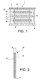
- FIG. 3 there is shown an installation 100 allowing the implementation of a method according to a preferred embodiment of the present invention, for testing the tightness of the bipolar structure 16 shown in FIG. figure 2 , and also called "bipolar electrode”.
- This structure 16 has a thickness "e" of 10 and 1000 microns, with a thickness of the aluminum substrate 14 preferably between 10 and 70 microns.
- the installation comprises a cavity 102, preferably cylindrical in shape of circular section, centered on the axis 104.
- the diameter D may be of the order of 16 mm.
- the cavity 102 is delimited by two concentric tips 106a, 106b mounted on one another, preferably by screwing.
- the bipolar structure 16 to be tested is sandwiched between the two ends, and delimits on either side thereof a first compartment 108a and a second compartment 108b of the cavity.
- the periphery of the structure 16 is sealingly connected to the cavity 102, on the inner wall thereof. As is visible on the figure 3 , the sealing is carried out using a seal 110 crushed between an end 112 of the tip 106a forming a shoulder, and the periphery of the structure 16.
- a support grid 114 is sandwiched between one end 116 of the tip 106b forming the shoulder, and the periphery of the bipolar structure 16. This grid is intended to limit the deformation of the structure 16 during the leak test, which will be described below.
- the first compartment 108a is closed opposite the bipolar structure 16 by a first closure part 120a, sealing against the first endpiece 106a.
- the closure piece 120a is pierced with a fluid inlet 122 connected to a supply 124, preferably delivering air.
- the second compartment 108b is closed opposite the bipolar structure 16 by a second closure member 120b, sealingly against the second endpiece 106b.
- the closure piece 120b is pierced with a fluid outlet 126, preferably open at atmospheric pressure.
- the sealing test method is continued by the circulation of air in the first compartment 108a, using the supply 124. This has the effect of pressing the structure 16 against the grid 114 arranged downstream.
- This air supply is preferably carried out at a flow rate Qv of the order of 60 to 700 liters / hour, and at an inlet speed Vmin, in the first compartment, of the order of 2.10 -5 to 2.10 -1. m / s.
- the tightness / permeability of the bipolar structure 16 is evaluated from a measurement of the air pressure difference in the first and second compartments, using appropriate sensors 130.
- the bipolar structure 16 may be deemed non-compliant when the measured pressure difference passes below a predetermined value, testifying to an unacceptable amount of gas joining the second compartment 108b by borrowing / cracks in the thickness of the structure 16. Such cracks generate indeed a risk of ion short circuit through the current collector 14.
- the predetermined value can be set by abacuses, preferably depending on a plurality of criteria such as the thickness of the structure 16, the porosity of its electrode layers, the temperature T measured by a sensor in the cavity, etc.
- the bipolar structure is then advantageously discarded before ending up in the stack intended to form the electrochemical generator.
- the bipolar structure 16 after calendering, must have a leak rate strictly less than 5.10 -5 Pa.m3 / s, and preferably strictly less than 1.10 -7 Pa.m3 / s .
- Such bipolar electrodes are also object of the present invention.
Landscapes
- Engineering & Computer Science (AREA)
- Chemical & Material Sciences (AREA)
- General Chemical & Material Sciences (AREA)
- Manufacturing & Machinery (AREA)
- Chemical Kinetics & Catalysis (AREA)
- Electrochemistry (AREA)
- Power Engineering (AREA)
- Microelectronics & Electronic Packaging (AREA)
- Physics & Mathematics (AREA)
- General Physics & Mathematics (AREA)
- Materials Engineering (AREA)
- Secondary Cells (AREA)
- Cell Electrode Carriers And Collectors (AREA)
- Battery Electrode And Active Subsutance (AREA)
Description
La présente invention se rapporte au domaine des générateurs électrochimiques, de préférence les piles et les accumulateurs au lithium, dont l'empilement comporte au moins une structure bipolaire, habituellement dénommée « électrode bipolaire ».The present invention relates to the field of electrochemical generators, preferably lithium batteries and accumulators, the stack of which comprises at least one bipolar structure, usually referred to as a "bipolar electrode".
Ce type de générateur électrochimique fonctionne sur le principe d'insertion ou de désinsertion (ou intercalation-désintercalation) de lithium sur au moins une électrode.This type of electrochemical generator operates on the principle of insertion or deinsertion (or intercalation-deintercalation) of lithium on at least one electrode.
En effet, la réaction électrochimique à l'origine de la production de courant met en jeu le transfert de cations lithium, par l'intermédiaire d'un électrolyte conducteur d'ions lithium, lesdits cations provenant d'une électrode négative venant soit s'intercaler dans le réseau accepteur de l'électrode positive, soit réalimenter l'électrolyte en ions lithium.Indeed, the electrochemical reaction at the origin of the production of current involves the transfer of lithium cations, via a lithium ion conductive electrolyte, said cations coming from a negative electrode coming either to intercalate in the acceptor network of the positive electrode, to replenish the electrolyte with lithium ions.
Ces générateurs électrochimiques trouvent leur application dans de nombreux domaines techniques, notamment dans l'alimentation des systèmes embarqués de faible épaisseur, comme les cartes de crédit, les étiquettes intelligentes, dans l'alimentation des téléphones mobiles, ou encore dans l'alimentation des véhicules électriques.These electrochemical generators find their application in many technical fields, particularly in the feeding of thin embedded systems, such as credit cards, smart labels, in the power supply of mobile phones, or in the power supply of vehicles. electric.
L'invention s'applique également au domaine des super-condensateurs électrochimiques dont au moins l'une des deux électrodes fonctionne par des réactions d'adsorption.The invention also applies to the field of electrochemical supercapacitors of which at least one of the two electrodes operates by adsorption reactions.
En référence aux
Le générateur comporte tout d'abord une électrode positive à l'extrémité haute de l'empilement, cette électrode comprenant un substrat conducteur en aluminium 2 et une couche active positive 4 à base de Li1,04Mn1,96O4, de LiFePO4, ou de tout autre matériau d'insertion du lithium. De manière analogue, il est prévu une électrode négative à l'extrémité basse de l'empilement, cette électrode comprenant un substrat conducteur en aluminium 6 et une couche active négative 8 à base de Li4Ti5O12.The generator firstly comprises a positive electrode at the high end of the stack, this electrode comprising an aluminum
Ces deux électrodes d'extrémité enserrent une ou plusieurs structures bipolaires, également dénommées électrodes bipolaires, chacune comprenant une couche active positive 10 et une couche active négative 12 de part et d'autre d'un substrat commun conducteur en aluminium 14, réalisé d'une seule pièce ou sous la forme de deux substrats superposés, tel que cela est décrit dans le document
Chaque couche active est déposée sur la feuille métallique d'aluminium par enduction sur un substrat métallique d'une encre d'électrode comportant du matériau actif, du conducteur électronique et du polymère, usuellement le polyfluorure de vinylidène lorsque les électrodes sont réalisées par voie organique. Le polymère est dissous dans un solvant, qui est généralement la N-méthyle Pyrollidone. Après évaporation de ce dernier, le polymère, parfaitement dispersé avec les poudres, permet l'accroche des grains de matériaux actifs et de conducteur électronique entre eux et sur le collecteur de courant en aluminium.Each active layer is deposited on the aluminum metal sheet by coating a metal substrate with an electrode ink comprising active material, the electronic conductor and the polymer, usually polyvinylidene fluoride when the electrodes are produced organically. . The polymer is dissolved in a solvent, which is generally N-methyl pyrollidone. After evaporation of the latter, the polymer, perfectly dispersed with the powders, allows the adhesion of the grains of active materials and electronic conductor between them and on the aluminum current collector.
De plus, les électrodes agencées aux extrémités de l'empilement sont séparées de l'électrode bipolaire par deux séparateurs microporeux 18, 20, respectivement en contact avec les électrodes 12 et 10 de la structure bipolaire.In addition, the electrodes arranged at the ends of the stack are separated from the bipolar electrode by two
Enfin, l'étanchéité de l'ensemble est assurée par un joint 22 généralement à base de polytétrafluoroéthylène (PTFE), éventuellement constitué de plusieurs éléments, et entourant la périphérie de l'empilement.Finally, the seal of the assembly is provided by a seal 22 generally based on polytetrafluoroethylene (PTFE), possibly consisting of several elements, and surrounding the periphery of the stack.
L'accumulateur montré sur la
L'architecture est ainsi qualifiée de bipolaire, car elle comprend une couche active positive d'une cellule et une couche active négative d'une cellule adjacente qui sont supportées par une même structure à collecteur de courant, qualifiée elle-même d'électrode bipolaire. L'architecture d'un accumulateur bipolaire correspond ainsi à la mise en série interne de plusieurs accumulateurs monopolaires par l'intermédiaire des électrodes ou collecteurs de courant bipolaires, avec notamment l'avantage d'avoir une résistance électrique réduite par rapport à des accumulateurs monopolaires conventionnels reliés en série par des connecteurs extérieurs. A cet égard, il est connu de nombreux brevets et demandes de brevets concernant de telles batteries bipolaires, tels que
Lorsque l'étanchéité périphérique du générateur électrochimique fait défaut, des éléments visuels majeurs en témoignent, comme une fuite de l'électrolyte liquide, une prise en eau de l'électrolyte pouvant conduire à une corrosion de l'aluminium en commençant par sa périphérie. En revanche, l'étanchéité des structures bipolaires n'est pas décelable visuellement, et aucune technique n'est connue pour la tester.When the peripheral sealing of the electrochemical generator is lacking, major visual elements testify, as a leakage of the liquid electrolyte, a water intake of the electrolyte that can lead to corrosion of the aluminum starting from its periphery. In contrast, the tightness of bipolar structures is not detectable visually, and no technique is known to test it.
Cela peut s'avérer problématique, étant donné qu'il existe un risque de court-circuit ionique via le collecteur de courant lui-même, qui peut en effet se retrouver perforé lors de la fabrication des structures bipolaires, et en particulier lors de l'étape de compression des électrodes par calandrage et/ou pressage. Une telle étape est effectivement mise en oeuvre afin d'atteindre les porosités et épaisseurs cibles pour les électrodes sous forme de couches adhérant au collecteur de courant. Elle s'effectue généralement en passant la structure bipolaire entre deux rouleaux compresseurs provoquant son chauffage et son calandrage.This can be problematic, since there is a risk of ion short circuit via the current collector itself, which can indeed be perforated during the manufacture of bipolar structures, and in particular when the step of compressing the electrodes by calendering and / or pressing. Such a step is effectively implemented in order to achieve the porosities and target thicknesses for the electrodes in the form of layers adhering to the current collector. It is generally carried out by passing the bipolar structure between two compressor rollers causing its heating and calendering.
A cet égard, il est rappelé que pour optimiser le fonctionnement de la structure bipolaire, il est nécessaire de compresser ses deux couches formant électrodes sur le substrat, de sorte qu'elles adoptent une porosité optimale, dont la valeur dépend des applications visées pour l'accumulateur (faible pour un accumulateur à haute densité d'énergie, optimisée pour un accumulateur de puissance). La porosité doit être assez grande pour permettre la mouillabilité de l'électrode par l'électrolyte et optimiser la diffusion ionique pendant le cyclage de l'accumulateur. Elle doit également être diminuée au maximum pour améliorer le contact des grains de matériaux entre eux, et optimiser la conduction électrique dans l'électrode jusqu'au collecteur de courant. En général, la porosité des électrodes est optimale entre 25 et 40%, et typiquement autour de 40% pour un bon fonctionnement des électrodes en puissance.In this respect, it is recalled that in order to optimize the operation of the bipolar structure, it is necessary to compress its two electrode layers on the substrate, so that they adopt an optimal porosity, the value of which depends on the applications targeted for the accumulator (low for a high energy density battery, optimized for a power accumulator). The porosity must be large enough to allow the wettability of the electrode by the electrolyte and optimize the ion diffusion during cycling of the accumulator. It must also be minimized to improve the contact of the grains of materials with each other, and optimize the electrical conduction in the electrode to the current collector. In general, the porosity of the electrodes is optimal between 25 and 40%, and typically around 40% for proper operation of the electrodes in power.
Il est noté que dans le cas d'une batterie bipolaire, un fonctionnement en puissance est généralement préféré.It is noted that in the case of a bipolar battery, power operation is generally preferred.
Le choix d'une porosité plus élevée, par exemple 45%, peut être motivé par la diminution du risque de détérioration de la structure bipolaire lors de son calandrage, ainsi que par la non-altération des performances électrochimiques.The choice of a higher porosity, for example 45%, may be motivated by the decrease in risk of deterioration of the bipolar structure during its calendering, as well as the non-alteration of the electrochemical performances.
Habituellement, la détection des microfuites est seulement réalisée après l'empilement des éléments de la cellule, et sa mise en fonctionnement. Elle est réalisée par détection de courants ioniques anormaux. Cela implique qu'elle a été entièrement assemblée et activée, et que ses composants non-défectueux ne peuvent plus être récupérés.Usually, the detection of micro-leaks is only performed after the stacking of the elements of the cell, and its setting into operation. It is performed by detecting abnormal ionic currents. This implies that it has been fully assembled and activated, and that its non-defective components can no longer be recovered.
De l'art antérieur, il est également connu les documents
Le document
Il en est de même pour le document
L'invention a donc pour but de remédier au moins partiellement aux inconvénients mentionnés ci-dessus, relatifs aux réalisations de l'art antérieur.The invention therefore aims to at least partially overcome the disadvantages mentioned above, relating to the achievements of the prior art.
Pour ce faire, l'invention a pour objet un procédé de test d'étanchéité d'une structure bipolaire comprenant un substrat en forme de feuille formant collecteur de courant, ainsi que deux électrodes en forme de couches respectivement agencées sur les surfaces opposées du substrat, le procédé comprenant les étapes suivantes :
- mise en place de la structure bipolaire dans une cavité de manière à délimiter au sein de celle-ci un premier et un second compartiments séparés par cette structure bipolaire dont la périphérie est reliée de manière étanche à la cavité ;
- mise en circulation d'un fluide dans le premier compartiment de la cavité, en direction du second compartiment ; et
- évaluation de l'étanchéité de la structure bipolaire à partir d'une mesure de la différence de pression du fluide dans les premier et second compartiments.
- placing the bipolar structure in a cavity so as to delimit within it first and second compartments separated by this bipolar structure whose periphery is sealingly connected to the cavity;
- circulating a fluid in the first compartment of the cavity, towards the second compartment; and
- evaluation of the tightness of the bipolar structure from a measurement of the fluid pressure difference in the first and second compartments.
L'invention est ainsi avantageuse en ce qu'elle se révèle extrêmement fiable et simple pour détecter d'éventuelles fuites à travers la structure bipolaire à tester. Cette solution permet par conséquent de tester les composants avant de les introduire au sein d'un empilement bipolaire, de préférence un générateur électrochimique, puis d'évincer les structures bipolaires défectueuses.The invention is thus advantageous in that it is extremely reliable and simple to detect possible leaks through the bipolar structure to be tested. This solution therefore makes it possible to test the components before introducing them into a bipolar stack, preferably an electrochemical generator, and then to remove the defective bipolar structures.
En d'autres termes, le principe de l'invention repose sur la mesure de la perméabilité intrinsèque de la structure bipolaire, pour juger de son niveau d'intégrité en termes d'étanchéité. Ce test, en fonction de la valeur de la différence de pression mesurée renseignant sur sa perméabilité, permet ainsi de déterminer si la structure bipolaire peut ou non être intégrée dans un empilement pour constituer une électrode bipolaire étanche, avant l'assemblage, l'activation et la mise en fonctionnement/cyclage.In other words, the principle of the invention is based on the measurement of the intrinsic permeability of the bipolar structure, to judge its level of integrity in terms of sealing. This test, as a function of the value of the measured pressure difference giving information on its permeability, thus makes it possible to determine whether or not the bipolar structure can be integrated in a stack to constitute a sealed bipolar electrode, before assembly, activation and commissioning / cycling.
A titre indicatif, il est noté que la perméabilité d'un milieu poreux ou fissuré caractérise son aptitude à laisser circuler un fluide au sein de son espace. Elle dépend de la structure interne de l'espace poreux ou fissuré, et particulièrement de la forme, connectivité de ses différents éléments, etc. C'est une propriété de transport macroscopique exprimant le rapport entre une force (gradient de pression) imposée à un fluide pour traverser le milieu, et le flux (débit) résultant.As an indication, it is noted that the permeability of a porous or cracked medium characterizes its ability to circulate a fluid within its space. It depends on the internal structure of the porous or fissured space, and particularly on the shape, connectivity of its different elements, etc. It is a macroscopic transport property expressing the ratio between a force (pressure gradient) imposed on a fluid to cross the medium, and the resulting flow (flow).
De préférence, il est prévu une grille de support dans le second compartiment, avec la structure bipolaire plaquée contre cette grille. Cela évite les déformations de la structure bipolaire durant le test d'étanchéité.Preferably, there is provided a support grid in the second compartment, with the bipolar structure pressed against this grid. This avoids deformations of the bipolar structure during the leak test.
De préférence, ladite structure bipolaire présente une épaisseur totale comprise entre 10 et 1000 µm, encore plus préférentiellement entre 20 et 500 µm, et plus particulièrement de l'ordre de 125 ± 50 µm.Preferably, said bipolar structure has a total thickness of between 10 and 1000 μm, more preferably between 20 and 500 μm, and more particularly of the order of 125 ± 50 μm.
De préférence, le fluide est de l'air et est introduit dans le premier compartiment avec un débit de l'ordre de 60 à 700 litres/heure.Preferably, the fluid is air and is introduced into the first compartment with a flow rate of the order of 60 to 700 liters / hour.
De préférence, le fluide est de l'air et est introduit dans le premier compartiment avec une vitesse de l'ordre de 2.10-5 à 2.10-1 m/s.Preferably, the fluid is air and is introduced into the first compartment with a speed of the order of 2.10 -5 to 2.10 -1 m / s.
De préférence, ladite structure bipolaire est destinée à être intégrée dans un générateur électrochimique bipolaire ou un super-condensateur avec au moins une électrode de la structure bipolaire fonctionnant par insertion d'ions lithium ou par phénomène capacitif.Preferably, said bipolar structure is intended to be integrated in a bipolar electrochemical generator or a super-capacitor with at least one electrode of the bipolar structure operating by insertion of lithium ions or by capacitive phenomenon.
Comme évoqué ci-dessus, la structure selon l'invention est destinée à constituer une « électrode bipolaire » avec un substrat en forme de feuille formant collecteur de courant, ainsi que deux électrodes en forme de couches respectivement agencées sur les surfaces opposées du substrat. De préférence, les électrodes agencées de part et d'autres du collecteur de courant comprennent au moins un liant de type polymérique, un matériau d'électrode, et avantageusement un conducteur électronique tel que du carbone.As mentioned above, the structure according to the invention is intended to constitute a "bipolar electrode" with a sheet-shaped substrate forming a current collector, as well as two layer-shaped electrodes respectively arranged on the opposite surfaces of the substrate. Preferably, the electrodes arranged on either side of the current collector comprise at least one binder of polymeric type, an electrode material, and advantageously an electronic conductor such as carbon.
Par liant polymérique, on entend de préférence un liant choisi parmi le PVdF, la carboyméthylcellulose, l'acide polyacrylique, etc.By polymeric binder is preferably meant a binder selected from PVdF, carboymethylcellulose, polyacrylic acid, etc.
Parmi les matériaux actifs d'électrode positive, on peut citer LiCoO2, LiNi0.8Co0.15A10.05O2, Li1,04Mn1,96O4 LiMn2O4, LiNi0.33Mn0.33Co0.33O2, LiFePO4, un composé à base de soufre, ou un mélange de ces derniers.Among the active materials of positive electrode, there may be mentioned LiCoO2, LiNi0.8Co0.15A10.05O2, Li 1.04 Mn 1.96 O 4 LiMn2O4, LiNi0.33Mn0.33Co0.33O2, LiFePO4, a sulfur-based compound , or a mixture of these.
Parmi les matériaux actifs d'électrode négative, on peut citer le TiO2, Li4Ti5O12, le silicium, l'étain, un oxyde de silicium et d'étain, un composé à base de carbone type carbone graphite ou un mélange de ces derniers.Among the active negative electrode materials, mention may be made of
Le collecteur de courant selon l'invention est constitué d'un matériau choisi parmi un ou plusieurs métal(aux), un polymère conducteur électronique ou un matériau composite conducteur électronique. Parmi les métaux, on peut citer l'aluminium, le cuivre, le nickel, ou un mélange cuivre et aluminium.The current collector according to the invention consists of a material chosen from one or more metals (aux), an electronically conductive polymer or an electronically conductive composite material. Among the metals, mention may be made of aluminum, copper, nickel, or a mixture of copper and aluminum.
De préférence la feuille formant le collecteur de courant est en aluminium.Preferably the sheet forming the current collector is aluminum.
Selon un développement de l'invention, l'électrode bipolaire est calandrée et le test d'étanchéité est pratiqué après calandrage, et avant la mise en place de la structure bipolaire dans une batterie bipolaire.According to a development of the invention, the bipolar electrode is calendered and the leak test is performed after calendering, and before the establishment of the bipolar structure in a bipolar battery.
L'invention a également pour objet une structure bipolaire comportant un substrat en forme de feuille formant collecteur de courant, ainsi que deux électrodes en forme de couches respectivement agencées sur les surfaces opposées du substrat, ladite structure présentant un taux de fuite strictement inférieur à 5.10-5 Pa.m3/s, et de préférence strictement inférieur à 1.10-7 Pa.m3/s. Les taux de fuite mentionnés ci-dessus sont préférentiellement ceux observés après calandrage de la structure bipolaire.The invention also relates to a bipolar structure comprising a sheet-shaped substrate forming a current collector, and two layer-shaped electrodes respectively arranged on the opposite surfaces of the substrate, said structure having a leak rate strictly less than 5.10. -5 Pa.m3 / s, and preferably strictly less than 1.10 -7 Pa.m3 / s. The leakage rates mentioned above are preferably those observed after calendering of the bipolar structure.
D'autres avantages et caractéristiques de l'invention apparaîtront dans la description détaillée non limitative ci-dessous.Other advantages and features of the invention will become apparent in the detailed non-limiting description below.
Cette description sera faite au regard des dessins annexés parmi lesquels ;
- la
figure 1 , déjà décrite, représente une vue schématique en coupe d'un générateur électrochimique bipolaire au lithium, intégrant une structure bipolaire destinée à subir un test d'étanchéité selon l'invention ; - la
figure 2 représente une vue schématique en coupe de la structure bipolaire intégrée au générateur de lafigure 1 ; - la
figure 3 représente une vue schématique en coupe d'une installation permettant la mise en oeuvre d'un procédé selon un mode de réalisation préféré de la présente invention.
- the
figure 1 , already described, represents a schematic sectional view of a lithium bipolar electrochemical generator, incorporating a bipolar structure intended to undergo a leak test according to the invention; - the
figure 2 represents a schematic sectional view of the bipolar structure integrated into the generator of thefigure 1 ; - the
figure 3 is a schematic sectional view of an installation for carrying out a method according to a preferred embodiment of the present invention.
En référence à la
Cette structure 16 présente une épaisseur « e » comprise 10 et 1000 µm, avec une épaisseur du substrat en aluminium 14 de préférence comprise entre 10 et 70 µm.This
L'installation comprend une cavité 102, de préférence de forme cylindrique de section circulaire, centrée sur l'axe 104. Le diamètre D peut être de l'ordre de 16 mm. La cavité 102 est délimitée par deux embouts concentriques 106a, 106b montés l'un sur l'autre, de préférence par vissage. La structure bipolaire 16 à tester est enserrée entre les deux embouts, et délimite de part et d'autre de celle-ci un premier compartiment 108a et un second compartiment 108b de la cavité. Pour ce faire, la périphérie de la structure 16 est reliée de manière étanche à la cavité 102, sur la paroi intérieure de celle-ci. Comme cela est visible sur la
Le premier compartiment 108a est fermé à l'opposé de la structure bipolaire 16 par une première pièce de fermeture 120a, en appui étanche contre le premier embout 106a. La pièce de fermeture 120a est percée d'une entrée de fluide 122 reliée à une alimentation 124, délivrant de préférence de l'air.The
De manière analogue, le second compartiment 108b est fermé à l'opposé de la structure bipolaire 16 par une seconde pièce de fermeture 120b, en appui étanche contre le second embout 106b. La pièce de fermeture 120b est percée d'une sortie de fluide 126, de préférence ouverte à la pression atmosphérique.Similarly, the
Une fois que l'installation 100 montrée sur la
Cette alimentation en air s'effectue de préférence à un débit Qv de l'ordre 60 à 700 litres/heure, et à une vitesse d'entrée Vmin, dans le premier compartiment, de l'ordre de 2.10-5 à 2.10-1 m/s.This air supply is preferably carried out at a flow rate Qv of the order of 60 to 700 liters / hour, and at an inlet speed Vmin, in the first compartment, of the order of 2.10 -5 to 2.10 -1. m / s.
Ensuite, l'étanchéité / la perméabilité de la structure bipolaire 16 est évaluée à partir d'une mesure de la différence de pression de l'air dans les premier et second compartiments, à l'aide de capteurs appropriés 130.Next, the tightness / permeability of the
A titre d'exemple indicatif, la structure bipolaire 16 peut être réputée non-conforme lorsque la différence de pression mesurée passe au-dessous d'une valeur prédéterminée, témoignant d'une quantité non acceptable de gaz rejoignant le second compartiment 108b en empruntant une / des fissures dans l'épaisseur de la structure 16. De telles fissures génèrent en effet un risque de court-circuit ionique à travers le collecteur de courant 14.By way of indicative example, the
La valeur prédéterminée peut être fixée par des abaques, dépendant de préférence d'une pluralité de critères comme l'épaisseur de la structure 16, la porosité de ses couches formant électrodes, la température T mesurée par un capteur dans la cavité, etc.The predetermined value can be set by abacuses, preferably depending on a plurality of criteria such as the thickness of the
En cas de non-conformité, la structure bipolaire est alors avantageusement écartée avant de se retrouver dans l'empilement destiné à former le générateur électrochimique.In case of non-compliance, the bipolar structure is then advantageously discarded before ending up in the stack intended to form the electrochemical generator.
A titre d'exemple, pour être conforme, la structure bipolaire 16, après calandrage, doit présenter un taux de fuite strictement inférieur à 5.10-5 Pa.m3/s, et de préférence strictement inférieur à 1.10-7 Pa.m3/s. De telles électrodes bipolaires sont également objet de la présente invention.By way of example, to be consistent, the
Bien entendu, diverses modifications peuvent être apportées par l'homme du métier à l'invention qui vient d'être décrite, uniquement à titre d'exemples non limitatifs.Of course, various modifications may be made by those skilled in the art to the invention which has just been described, solely by way of non-limiting examples.
Claims (6)
- Method for evaluating the sealing of a bipolar structure (16) including a sheet-like substrate (14) forming a current collector, as well as two electrodes (10, 12) in the form of films arranged on the opposite surfaces of the substrate (14), respectively, the method including the following steps:- placing the bipolar structure (16) in a cavity (102) so as to define first and second compartments (108a, 108b) therein, which are separated by said bipolar structure, the periphery of which is sealingly connected to the cavity (102);- circulating a fluid in the first compartment (108a) of the cavity toward the second compartment (108b);- evaluating the sealing of the bipolar structure (16) from a measurement of the difference in the pressure of the fluid in the first and second compartments.
- Method according to claim 1, wherein a support grid (114) is provided in the second compartment (108b), with the bipolar structure (16) pressed against said grid.
- Method according to claim 1 or claim 2, wherein said bipolar structure (16) has a total thickness (e) comprised between 10 and 1000 µm.
- Method according to any of the preceding claims, wherein the fluid is introduced into the first compartment (108a) with a flow rate of the order of 60 to 700 litres/hour.
- Method according to any of the preceding claims, wherein the fluid is introduced into the first compartment (108a) with a velocity of the order of 2.10-5 to 2.10-1 m/s.
- Method according to any of the preceding claims, wherein said bipolar structure (16) is intended to be integrated in a bipolar electrochemical generator or a super-capacitor with at least one electrode of the bipolar structure operating by insertion of lithium ions or by capacitive phenomenon.
Applications Claiming Priority (2)
| Application Number | Priority Date | Filing Date | Title |
|---|---|---|---|
| FR1158214A FR2980306B1 (en) | 2011-09-15 | 2011-09-15 | METHOD FOR TESTING THE SEALING OF A BIPOLAR STRUCTURE FOR AN ELECTROCHEMICAL GENERATOR |
| PCT/EP2012/068001 WO2013037917A1 (en) | 2011-09-15 | 2012-09-13 | Method for evaluating the sealing of a bipolar structure for an electrochemical generator |
Publications (2)
| Publication Number | Publication Date |
|---|---|
| EP2756535A1 EP2756535A1 (en) | 2014-07-23 |
| EP2756535B1 true EP2756535B1 (en) | 2015-09-09 |
Family
ID=46829798
Family Applications (1)
| Application Number | Title | Priority Date | Filing Date |
|---|---|---|---|
| EP12756764.2A Active EP2756535B1 (en) | 2011-09-15 | 2012-09-13 | Method for evaluating the sealing of a bipolar structure for an electrochemical generator |
Country Status (4)
| Country | Link |
|---|---|
| US (1) | US20150040646A1 (en) |
| EP (1) | EP2756535B1 (en) |
| FR (1) | FR2980306B1 (en) |
| WO (1) | WO2013037917A1 (en) |
Families Citing this family (4)
| Publication number | Priority date | Publication date | Assignee | Title |
|---|---|---|---|---|
| CN107478393A (en) * | 2017-09-22 | 2017-12-15 | 福建福安闽东亚南电机有限公司 | A kind of leakage detection apparatus of fuel cell membrane electrode |
| JP7205136B2 (en) * | 2018-09-25 | 2023-01-17 | 大日本印刷株式会社 | Electrical storage device valve device and electrical storage device |
| JP7165303B2 (en) * | 2019-03-08 | 2022-11-04 | トヨタ自動車株式会社 | Battery pack leak inspection method and leak inspection device |
| CN110082047B (en) * | 2019-04-15 | 2021-12-14 | 合肥国轩高科动力能源有限公司 | Upper cover plate compression protection device for lithium battery pack sealing test |
Family Cites Families (14)
| Publication number | Priority date | Publication date | Assignee | Title |
|---|---|---|---|---|
| US5595839A (en) * | 1994-10-13 | 1997-01-21 | Yardney Technical Products, Inc. | Bipolar lithium-ion rechargeable battery |
| DE19704584C2 (en) * | 1997-02-07 | 1999-02-25 | Dornier Gmbh | Double-layer capacitor consisting of several double-layer capacitor single cells, usable as energy storage, current source or electronic component |
| US7150936B2 (en) * | 2000-10-25 | 2006-12-19 | Nec Tokin Tochigi, Ltd. | Sealed battery and method for manufacturing sealed battery |
| SE520007C8 (en) | 2001-09-19 | 2006-05-16 | Nilar Europ Ab | A bipolar battery, a method of manufacturing a bipolar battery and car plate composition |
| FR2832859B1 (en) * | 2001-11-28 | 2004-01-09 | Commissariat Energie Atomique | LITHIUM ELECTROCHEMICAL GENERATOR COMPRISING AT LEAST ONE BIPOLAR ELECTRODE WITH ALUMINUM OR ALUMINUM ALLOY CONDUCTIVE SUBSTRATES |
| JP4144312B2 (en) | 2002-10-08 | 2008-09-03 | 日産自動車株式会社 | Bipolar battery |
| JP4135473B2 (en) * | 2002-11-07 | 2008-08-20 | 日産自動車株式会社 | Bipolar battery |
| JP4155054B2 (en) | 2003-02-18 | 2008-09-24 | 日産自動車株式会社 | Bipolar battery |
| JP4238645B2 (en) | 2003-06-12 | 2009-03-18 | 日産自動車株式会社 | Bipolar battery |
| JP5098150B2 (en) | 2004-12-07 | 2012-12-12 | 日産自動車株式会社 | Bipolar battery and manufacturing method thereof |
| US7748253B2 (en) * | 2004-12-08 | 2010-07-06 | Li-Cor, Inc. | Vent and soil flux measurement system |
| FR2881569B1 (en) * | 2005-02-01 | 2007-04-20 | Batscap Sa | SUPERCONDENSOR ELECTRODE WITH HIGH LOAD RATE AND EXTRUSION PROCESS |
| US7849730B2 (en) * | 2007-11-29 | 2010-12-14 | Atomic Energy Council-Institute Of Nuclear Energy Research | Device for testing the performance of a sealant for SOFC stacks |
| FR2927472B1 (en) * | 2008-02-11 | 2010-07-30 | Commissariat Energie Atomique | HYBRID SYSTEM FOR STORING ELECTRIC ENERGY WITH BIPOLAR ELECTRODES |
-
2011
- 2011-09-15 FR FR1158214A patent/FR2980306B1/en not_active Expired - Fee Related
-
2012
- 2012-09-13 US US14/344,740 patent/US20150040646A1/en not_active Abandoned
- 2012-09-13 EP EP12756764.2A patent/EP2756535B1/en active Active
- 2012-09-13 WO PCT/EP2012/068001 patent/WO2013037917A1/en active Application Filing
Also Published As
| Publication number | Publication date |
|---|---|
| FR2980306B1 (en) | 2013-10-11 |
| WO2013037917A1 (en) | 2013-03-21 |
| EP2756535A1 (en) | 2014-07-23 |
| US20150040646A1 (en) | 2015-02-12 |
| FR2980306A1 (en) | 2013-03-22 |
Similar Documents
| Publication | Publication Date | Title |
|---|---|---|
| EP2870655B1 (en) | Current collector with integrated leak-proofing means, bipolar battery comprising such a collector | |
| EP2686903B1 (en) | Method for determining when a li-ion cell comprising a negative electrode made of an alloy is fully charged, associated cell and battery | |
| EP2756535B1 (en) | Method for evaluating the sealing of a bipolar structure for an electrochemical generator | |
| EP2875538B1 (en) | Bipolar li-ion battery with improved seal and associated production process | |
| FR3006116A1 (en) | BIPOLAR LI-ON BATTERY WITH IMPROVED SEALING AND METHOD OF MAKING THE SAME. | |
| EP2904654B1 (en) | Bipolar battery including a current collector having a built-in sealing means, method for manufacturing such a battery | |
| US20180337383A1 (en) | Battery and manufacturing method of the same | |
| FR3037724A1 (en) | PROCESS FOR PRODUCING AN ELECTROCHEMICAL LITHIUM BATTERY BEAM WITH FOLDING OR WINDING OF THE SHEET END ON THE SAME | |
| FR3044169A1 (en) | LITHIUM-ION BIPOLAR BATTERY | |
| FR3034571A1 (en) | ELECTROCHEMICAL DEVICE, SUCH AS A MICROBATTERY OR AN ELECTROCHROME SYSTEM, COVERED BY AN ENCAPSULATION LAYER COMPRISING A BARRIER FILM AND AN ADHESIVE FILM, AND METHOD OF MAKING SUCH A DEVICE. | |
| WO2020245521A1 (en) | Composite conductive film for producing electrical energy storage batteries, method for producing such a film, and electrical storage battery using such a film | |
| EP3095147B1 (en) | Electrochemical accumulator with housing and terminal made of aluminum alloy | |
| FR2955974A1 (en) | ELECTROCHEMICAL ACCUMULATOR WITH PACKAGE COMPRISING AT LEAST ONE POLYARYLETHERCETONE (PAEK) SHEET, SHEET AND METHODS OF MAKING THE SAME | |
| WO2014141032A1 (en) | Bipolar li-ion battery with improved leaktightness and associated method of production | |
| FR3037725A1 (en) | METHOD FOR PRODUCING AN ELECTROCHEMICAL BEAM OF A LITHIUM BATTERY WITH METALLIC FOAM AT THE END OF STRIPS | |
| CA2825264A1 (en) | Current collecting plate pierced with horizontal holes, intended for a fuel cell | |
| FR3053842A1 (en) | METAL-ION ELECTROCHEMICAL ACCUMULATOR, HIGH CAPACITY AND FLEXIBILITY ENABLES GREAT CONFORMABILITY | |
| EP2826082B1 (en) | Lower weight li-ion electrochemical accumulator | |
| EP4187667A2 (en) | Method for producing an all-solid-state battery from a liquid electrolyte metal-ion electrochemical battery for thermal abuse testing | |
| EP3680963A1 (en) | Negative electrodes that can be used in storage batteries operating according to the principle of ion insertion and removal or alloy formation and storage battery comprising such an electrode | |
| EP4082055A1 (en) | Composite electrode comprising a metal and a polymer membrane, manufacturing method and battery containing same | |
| FR3113442A1 (en) | Energy storage cell comprising a composite separator to initiate a short circuit | |
| FR3128585A1 (en) | Metal-ion electrochemical accumulator incorporating a current collector formed by a thermoplastic polymer disc loaded with electrically conductive particles and/or fibers |
Legal Events
| Date | Code | Title | Description |
|---|---|---|---|
| PUAI | Public reference made under article 153(3) epc to a published international application that has entered the european phase |
Free format text: ORIGINAL CODE: 0009012 |
|
| 17P | Request for examination filed |
Effective date: 20140317 |
|
| AK | Designated contracting states |
Kind code of ref document: A1 Designated state(s): AL AT BE BG CH CY CZ DE DK EE ES FI FR GB GR HR HU IE IS IT LI LT LU LV MC MK MT NL NO PL PT RO RS SE SI SK SM TR |
|
| DAX | Request for extension of the european patent (deleted) | ||
| 17Q | First examination report despatched |
Effective date: 20150115 |
|
| REG | Reference to a national code |
Ref country code: DE Ref legal event code: R079 Ref document number: 602012010472 Country of ref document: DE Free format text: PREVIOUS MAIN CLASS: H01M0006480000 Ipc: H01M0010420000 |
|
| GRAP | Despatch of communication of intention to grant a patent |
Free format text: ORIGINAL CODE: EPIDOSNIGR1 |
|
| RIC1 | Information provided on ipc code assigned before grant |
Ipc: H01M 10/04 20060101ALI20150224BHEP Ipc: G01M 3/26 20060101ALI20150224BHEP Ipc: H01M 10/0525 20100101ALI20150224BHEP Ipc: H01M 6/48 20060101ALI20150224BHEP Ipc: H01G 11/14 20130101ALI20150224BHEP Ipc: H01M 4/02 20060101ALN20150224BHEP Ipc: H01M 4/04 20060101ALN20150224BHEP Ipc: H01M 10/42 20060101AFI20150224BHEP Ipc: H01G 11/80 20130101ALI20150224BHEP Ipc: H01M 6/50 20060101ALI20150224BHEP |
|
| INTG | Intention to grant announced |
Effective date: 20150320 |
|
| GRAS | Grant fee paid |
Free format text: ORIGINAL CODE: EPIDOSNIGR3 |
|
| GRAA | (expected) grant |
Free format text: ORIGINAL CODE: 0009210 |
|
| AK | Designated contracting states |
Kind code of ref document: B1 Designated state(s): AL AT BE BG CH CY CZ DE DK EE ES FI FR GB GR HR HU IE IS IT LI LT LU LV MC MK MT NL NO PL PT RO RS SE SI SK SM TR |
|
| REG | Reference to a national code |
Ref country code: GB Ref legal event code: FG4D Free format text: NOT ENGLISH |
|
| REG | Reference to a national code |
Ref country code: AT Ref legal event code: REF Ref document number: 748789 Country of ref document: AT Kind code of ref document: T Effective date: 20150915 Ref country code: CH Ref legal event code: EP |
|
| REG | Reference to a national code |
Ref country code: IE Ref legal event code: FG4D Free format text: LANGUAGE OF EP DOCUMENT: FRENCH |
|
| REG | Reference to a national code |
Ref country code: DE Ref legal event code: R096 Ref document number: 602012010472 Country of ref document: DE |
|
| REG | Reference to a national code |
Ref country code: NL Ref legal event code: MP Effective date: 20150909 |
|
| PG25 | Lapsed in a contracting state [announced via postgrant information from national office to epo] |
Ref country code: LT Free format text: LAPSE BECAUSE OF FAILURE TO SUBMIT A TRANSLATION OF THE DESCRIPTION OR TO PAY THE FEE WITHIN THE PRESCRIBED TIME-LIMIT Effective date: 20150909 Ref country code: NO Free format text: LAPSE BECAUSE OF FAILURE TO SUBMIT A TRANSLATION OF THE DESCRIPTION OR TO PAY THE FEE WITHIN THE PRESCRIBED TIME-LIMIT Effective date: 20151209 Ref country code: GR Free format text: LAPSE BECAUSE OF FAILURE TO SUBMIT A TRANSLATION OF THE DESCRIPTION OR TO PAY THE FEE WITHIN THE PRESCRIBED TIME-LIMIT Effective date: 20151210 Ref country code: LV Free format text: LAPSE BECAUSE OF FAILURE TO SUBMIT A TRANSLATION OF THE DESCRIPTION OR TO PAY THE FEE WITHIN THE PRESCRIBED TIME-LIMIT Effective date: 20150909 Ref country code: FI Free format text: LAPSE BECAUSE OF FAILURE TO SUBMIT A TRANSLATION OF THE DESCRIPTION OR TO PAY THE FEE WITHIN THE PRESCRIBED TIME-LIMIT Effective date: 20150909 |
|
| REG | Reference to a national code |
Ref country code: LT Ref legal event code: MG4D |
|
| REG | Reference to a national code |
Ref country code: AT Ref legal event code: MK05 Ref document number: 748789 Country of ref document: AT Kind code of ref document: T Effective date: 20150909 |
|
| PG25 | Lapsed in a contracting state [announced via postgrant information from national office to epo] |
Ref country code: SE Free format text: LAPSE BECAUSE OF FAILURE TO SUBMIT A TRANSLATION OF THE DESCRIPTION OR TO PAY THE FEE WITHIN THE PRESCRIBED TIME-LIMIT Effective date: 20150909 Ref country code: HR Free format text: LAPSE BECAUSE OF FAILURE TO SUBMIT A TRANSLATION OF THE DESCRIPTION OR TO PAY THE FEE WITHIN THE PRESCRIBED TIME-LIMIT Effective date: 20150909 Ref country code: ES Free format text: LAPSE BECAUSE OF FAILURE TO SUBMIT A TRANSLATION OF THE DESCRIPTION OR TO PAY THE FEE WITHIN THE PRESCRIBED TIME-LIMIT Effective date: 20150909 Ref country code: RS Free format text: LAPSE BECAUSE OF FAILURE TO SUBMIT A TRANSLATION OF THE DESCRIPTION OR TO PAY THE FEE WITHIN THE PRESCRIBED TIME-LIMIT Effective date: 20150909 |
|
| PG25 | Lapsed in a contracting state [announced via postgrant information from national office to epo] |
Ref country code: NL Free format text: LAPSE BECAUSE OF FAILURE TO SUBMIT A TRANSLATION OF THE DESCRIPTION OR TO PAY THE FEE WITHIN THE PRESCRIBED TIME-LIMIT Effective date: 20150909 |
|
| PG25 | Lapsed in a contracting state [announced via postgrant information from national office to epo] |
Ref country code: EE Free format text: LAPSE BECAUSE OF FAILURE TO SUBMIT A TRANSLATION OF THE DESCRIPTION OR TO PAY THE FEE WITHIN THE PRESCRIBED TIME-LIMIT Effective date: 20150909 Ref country code: CZ Free format text: LAPSE BECAUSE OF FAILURE TO SUBMIT A TRANSLATION OF THE DESCRIPTION OR TO PAY THE FEE WITHIN THE PRESCRIBED TIME-LIMIT Effective date: 20150909 Ref country code: IS Free format text: LAPSE BECAUSE OF FAILURE TO SUBMIT A TRANSLATION OF THE DESCRIPTION OR TO PAY THE FEE WITHIN THE PRESCRIBED TIME-LIMIT Effective date: 20160109 Ref country code: SK Free format text: LAPSE BECAUSE OF FAILURE TO SUBMIT A TRANSLATION OF THE DESCRIPTION OR TO PAY THE FEE WITHIN THE PRESCRIBED TIME-LIMIT Effective date: 20150909 Ref country code: IT Free format text: LAPSE BECAUSE OF FAILURE TO SUBMIT A TRANSLATION OF THE DESCRIPTION OR TO PAY THE FEE WITHIN THE PRESCRIBED TIME-LIMIT Effective date: 20150909 |
|
| REG | Reference to a national code |
Ref country code: CH Ref legal event code: PL |
|
| PG25 | Lapsed in a contracting state [announced via postgrant information from national office to epo] |
Ref country code: PL Free format text: LAPSE BECAUSE OF FAILURE TO SUBMIT A TRANSLATION OF THE DESCRIPTION OR TO PAY THE FEE WITHIN THE PRESCRIBED TIME-LIMIT Effective date: 20150909 Ref country code: RO Free format text: LAPSE BECAUSE OF FAILURE TO SUBMIT A TRANSLATION OF THE DESCRIPTION OR TO PAY THE FEE WITHIN THE PRESCRIBED TIME-LIMIT Effective date: 20150909 Ref country code: PT Free format text: LAPSE BECAUSE OF FAILURE TO SUBMIT A TRANSLATION OF THE DESCRIPTION OR TO PAY THE FEE WITHIN THE PRESCRIBED TIME-LIMIT Effective date: 20160111 Ref country code: AT Free format text: LAPSE BECAUSE OF FAILURE TO SUBMIT A TRANSLATION OF THE DESCRIPTION OR TO PAY THE FEE WITHIN THE PRESCRIBED TIME-LIMIT Effective date: 20150909 |
|
| REG | Reference to a national code |
Ref country code: DE Ref legal event code: R097 Ref document number: 602012010472 Country of ref document: DE |
|
| REG | Reference to a national code |
Ref country code: IE Ref legal event code: MM4A |
|
| PG25 | Lapsed in a contracting state [announced via postgrant information from national office to epo] |
Ref country code: MC Free format text: LAPSE BECAUSE OF FAILURE TO SUBMIT A TRANSLATION OF THE DESCRIPTION OR TO PAY THE FEE WITHIN THE PRESCRIBED TIME-LIMIT Effective date: 20150909 |
|
| PLBE | No opposition filed within time limit |
Free format text: ORIGINAL CODE: 0009261 |
|
| STAA | Information on the status of an ep patent application or granted ep patent |
Free format text: STATUS: NO OPPOSITION FILED WITHIN TIME LIMIT |
|
| PG25 | Lapsed in a contracting state [announced via postgrant information from national office to epo] |
Ref country code: IE Free format text: LAPSE BECAUSE OF NON-PAYMENT OF DUE FEES Effective date: 20150913 Ref country code: LI Free format text: LAPSE BECAUSE OF NON-PAYMENT OF DUE FEES Effective date: 20150930 Ref country code: CH Free format text: LAPSE BECAUSE OF NON-PAYMENT OF DUE FEES Effective date: 20150930 |
|
| 26N | No opposition filed |
Effective date: 20160610 |
|
| PG25 | Lapsed in a contracting state [announced via postgrant information from national office to epo] |
Ref country code: DK Free format text: LAPSE BECAUSE OF FAILURE TO SUBMIT A TRANSLATION OF THE DESCRIPTION OR TO PAY THE FEE WITHIN THE PRESCRIBED TIME-LIMIT Effective date: 20150909 Ref country code: SI Free format text: LAPSE BECAUSE OF FAILURE TO SUBMIT A TRANSLATION OF THE DESCRIPTION OR TO PAY THE FEE WITHIN THE PRESCRIBED TIME-LIMIT Effective date: 20150909 |
|
| REG | Reference to a national code |
Ref country code: FR Ref legal event code: PLFP Year of fee payment: 5 |
|
| PG25 | Lapsed in a contracting state [announced via postgrant information from national office to epo] |
Ref country code: MT Free format text: LAPSE BECAUSE OF FAILURE TO SUBMIT A TRANSLATION OF THE DESCRIPTION OR TO PAY THE FEE WITHIN THE PRESCRIBED TIME-LIMIT Effective date: 20150909 |
|
| PG25 | Lapsed in a contracting state [announced via postgrant information from national office to epo] |
Ref country code: HU Free format text: LAPSE BECAUSE OF FAILURE TO SUBMIT A TRANSLATION OF THE DESCRIPTION OR TO PAY THE FEE WITHIN THE PRESCRIBED TIME-LIMIT; INVALID AB INITIO Effective date: 20120913 Ref country code: SM Free format text: LAPSE BECAUSE OF FAILURE TO SUBMIT A TRANSLATION OF THE DESCRIPTION OR TO PAY THE FEE WITHIN THE PRESCRIBED TIME-LIMIT Effective date: 20150909 Ref country code: BG Free format text: LAPSE BECAUSE OF FAILURE TO SUBMIT A TRANSLATION OF THE DESCRIPTION OR TO PAY THE FEE WITHIN THE PRESCRIBED TIME-LIMIT Effective date: 20150909 |
|
| PG25 | Lapsed in a contracting state [announced via postgrant information from national office to epo] |
Ref country code: CY Free format text: LAPSE BECAUSE OF FAILURE TO SUBMIT A TRANSLATION OF THE DESCRIPTION OR TO PAY THE FEE WITHIN THE PRESCRIBED TIME-LIMIT Effective date: 20150909 |
|
| PG25 | Lapsed in a contracting state [announced via postgrant information from national office to epo] |
Ref country code: BE Free format text: LAPSE BECAUSE OF NON-PAYMENT OF DUE FEES Effective date: 20150930 |
|
| REG | Reference to a national code |
Ref country code: FR Ref legal event code: PLFP Year of fee payment: 6 |
|
| PG25 | Lapsed in a contracting state [announced via postgrant information from national office to epo] |
Ref country code: LU Free format text: LAPSE BECAUSE OF NON-PAYMENT OF DUE FEES Effective date: 20150913 |
|
| PG25 | Lapsed in a contracting state [announced via postgrant information from national office to epo] |
Ref country code: TR Free format text: LAPSE BECAUSE OF FAILURE TO SUBMIT A TRANSLATION OF THE DESCRIPTION OR TO PAY THE FEE WITHIN THE PRESCRIBED TIME-LIMIT Effective date: 20150909 Ref country code: MK Free format text: LAPSE BECAUSE OF FAILURE TO SUBMIT A TRANSLATION OF THE DESCRIPTION OR TO PAY THE FEE WITHIN THE PRESCRIBED TIME-LIMIT Effective date: 20150909 |
|
| REG | Reference to a national code |
Ref country code: FR Ref legal event code: PLFP Year of fee payment: 7 |
|
| PG25 | Lapsed in a contracting state [announced via postgrant information from national office to epo] |
Ref country code: AL Free format text: LAPSE BECAUSE OF FAILURE TO SUBMIT A TRANSLATION OF THE DESCRIPTION OR TO PAY THE FEE WITHIN THE PRESCRIBED TIME-LIMIT Effective date: 20150909 |
|
| PGFP | Annual fee paid to national office [announced via postgrant information from national office to epo] |
Ref country code: GB Payment date: 20190919 Year of fee payment: 8 |
|
| PGFP | Annual fee paid to national office [announced via postgrant information from national office to epo] |
Ref country code: DE Payment date: 20200910 Year of fee payment: 9 |
|
| GBPC | Gb: european patent ceased through non-payment of renewal fee |
Effective date: 20200913 |
|
| PG25 | Lapsed in a contracting state [announced via postgrant information from national office to epo] |
Ref country code: GB Free format text: LAPSE BECAUSE OF NON-PAYMENT OF DUE FEES Effective date: 20200913 |
|
| REG | Reference to a national code |
Ref country code: DE Ref legal event code: R119 Ref document number: 602012010472 Country of ref document: DE |
|
| PG25 | Lapsed in a contracting state [announced via postgrant information from national office to epo] |
Ref country code: DE Free format text: LAPSE BECAUSE OF NON-PAYMENT OF DUE FEES Effective date: 20220401 |
|
| PGFP | Annual fee paid to national office [announced via postgrant information from national office to epo] |
Ref country code: FR Payment date: 20230922 Year of fee payment: 12 |