EP2756330B1 - Ultrasound imaging console - Google Patents
Ultrasound imaging console Download PDFInfo
- Publication number
- EP2756330B1 EP2756330B1 EP11773833.6A EP11773833A EP2756330B1 EP 2756330 B1 EP2756330 B1 EP 2756330B1 EP 11773833 A EP11773833 A EP 11773833A EP 2756330 B1 EP2756330 B1 EP 2756330B1
- Authority
- EP
- European Patent Office
- Prior art keywords
- ultrasound
- signal
- ultrasound probe
- beamformer
- signals
- Prior art date
- Legal status (The legal status is an assumption and is not a legal conclusion. Google has not performed a legal analysis and makes no representation as to the accuracy of the status listed.)
- Active
Links
- 238000012285 ultrasound imaging Methods 0.000 title claims description 8
- 239000000523 sample Substances 0.000 claims description 110
- 238000002604 ultrasonography Methods 0.000 claims description 78
- 238000000034 method Methods 0.000 claims description 21
- 238000003491 array Methods 0.000 claims description 18
- 238000004891 communication Methods 0.000 claims description 10
- 238000003780 insertion Methods 0.000 claims description 5
- 230000037431 insertion Effects 0.000 claims description 5
- 238000012545 processing Methods 0.000 claims description 5
- 230000005284 excitation Effects 0.000 claims 2
- 238000003384 imaging method Methods 0.000 description 11
- 238000002592 echocardiography Methods 0.000 description 6
- 230000005540 biological transmission Effects 0.000 description 3
- 230000000295 complement effect Effects 0.000 description 3
- 230000008569 process Effects 0.000 description 3
- 238000003325 tomography Methods 0.000 description 3
- 230000004075 alteration Effects 0.000 description 2
- 238000013459 approach Methods 0.000 description 2
- 238000013329 compounding Methods 0.000 description 2
- 238000001914 filtration Methods 0.000 description 2
- 230000003340 mental effect Effects 0.000 description 2
- 238000012986 modification Methods 0.000 description 2
- 230000004048 modification Effects 0.000 description 2
- 210000000056 organ Anatomy 0.000 description 2
- 230000037361 pathway Effects 0.000 description 2
- 230000035939 shock Effects 0.000 description 2
- 239000004575 stone Substances 0.000 description 2
- 230000000007 visual effect Effects 0.000 description 2
- 208000000913 Kidney Calculi Diseases 0.000 description 1
- 206010029148 Nephrolithiasis Diseases 0.000 description 1
- 230000003187 abdominal effect Effects 0.000 description 1
- 238000001574 biopsy Methods 0.000 description 1
- 230000001427 coherent effect Effects 0.000 description 1
- 150000001875 compounds Chemical class 0.000 description 1
- 230000002596 correlated effect Effects 0.000 description 1
- 230000000875 corresponding effect Effects 0.000 description 1
- 238000000315 cryotherapy Methods 0.000 description 1
- 230000001419 dependent effect Effects 0.000 description 1
- 238000003745 diagnosis Methods 0.000 description 1
- 238000006073 displacement reaction Methods 0.000 description 1
- 230000010349 pulsation Effects 0.000 description 1
- 230000004044 response Effects 0.000 description 1
- 239000007787 solid Substances 0.000 description 1
- 230000003595 spectral effect Effects 0.000 description 1
- 230000003068 static effect Effects 0.000 description 1
- 230000008685 targeting Effects 0.000 description 1
Images


Classifications
-
- A—HUMAN NECESSITIES
- A61—MEDICAL OR VETERINARY SCIENCE; HYGIENE
- A61B—DIAGNOSIS; SURGERY; IDENTIFICATION
- A61B8/00—Diagnosis using ultrasonic, sonic or infrasonic waves
- A61B8/44—Constructional features of the ultrasonic, sonic or infrasonic diagnostic device
- A61B8/4477—Constructional features of the ultrasonic, sonic or infrasonic diagnostic device using several separate ultrasound transducers or probes
-
- G—PHYSICS
- G01—MEASURING; TESTING
- G01S—RADIO DIRECTION-FINDING; RADIO NAVIGATION; DETERMINING DISTANCE OR VELOCITY BY USE OF RADIO WAVES; LOCATING OR PRESENCE-DETECTING BY USE OF THE REFLECTION OR RERADIATION OF RADIO WAVES; ANALOGOUS ARRANGEMENTS USING OTHER WAVES
- G01S15/00—Systems using the reflection or reradiation of acoustic waves, e.g. sonar systems
- G01S15/88—Sonar systems specially adapted for specific applications
- G01S15/89—Sonar systems specially adapted for specific applications for mapping or imaging
- G01S15/8906—Short-range imaging systems; Acoustic microscope systems using pulse-echo techniques
- G01S15/8909—Short-range imaging systems; Acoustic microscope systems using pulse-echo techniques using a static transducer configuration
-
- A—HUMAN NECESSITIES
- A61—MEDICAL OR VETERINARY SCIENCE; HYGIENE
- A61B—DIAGNOSIS; SURGERY; IDENTIFICATION
- A61B8/00—Diagnosis using ultrasonic, sonic or infrasonic waves
- A61B8/13—Tomography
- A61B8/14—Echo-tomography
- A61B8/145—Echo-tomography characterised by scanning multiple planes
-
- A—HUMAN NECESSITIES
- A61—MEDICAL OR VETERINARY SCIENCE; HYGIENE
- A61B—DIAGNOSIS; SURGERY; IDENTIFICATION
- A61B8/00—Diagnosis using ultrasonic, sonic or infrasonic waves
- A61B8/42—Details of probe positioning or probe attachment to the patient
- A61B8/4209—Details of probe positioning or probe attachment to the patient by using holders, e.g. positioning frames
-
- A—HUMAN NECESSITIES
- A61—MEDICAL OR VETERINARY SCIENCE; HYGIENE
- A61B—DIAGNOSIS; SURGERY; IDENTIFICATION
- A61B8/00—Diagnosis using ultrasonic, sonic or infrasonic waves
- A61B8/44—Constructional features of the ultrasonic, sonic or infrasonic diagnostic device
- A61B8/4444—Constructional features of the ultrasonic, sonic or infrasonic diagnostic device related to the probe
-
- A—HUMAN NECESSITIES
- A61—MEDICAL OR VETERINARY SCIENCE; HYGIENE
- A61B—DIAGNOSIS; SURGERY; IDENTIFICATION
- A61B8/00—Diagnosis using ultrasonic, sonic or infrasonic waves
- A61B8/44—Constructional features of the ultrasonic, sonic or infrasonic diagnostic device
- A61B8/4483—Constructional features of the ultrasonic, sonic or infrasonic diagnostic device characterised by features of the ultrasound transducer
-
- A—HUMAN NECESSITIES
- A61—MEDICAL OR VETERINARY SCIENCE; HYGIENE
- A61B—DIAGNOSIS; SURGERY; IDENTIFICATION
- A61B8/00—Diagnosis using ultrasonic, sonic or infrasonic waves
- A61B8/52—Devices using data or image processing specially adapted for diagnosis using ultrasonic, sonic or infrasonic waves
- A61B8/5207—Devices using data or image processing specially adapted for diagnosis using ultrasonic, sonic or infrasonic waves involving processing of raw data to produce diagnostic data, e.g. for generating an image
-
- A—HUMAN NECESSITIES
- A61—MEDICAL OR VETERINARY SCIENCE; HYGIENE
- A61B—DIAGNOSIS; SURGERY; IDENTIFICATION
- A61B8/00—Diagnosis using ultrasonic, sonic or infrasonic waves
- A61B8/56—Details of data transmission or power supply
-
- A—HUMAN NECESSITIES
- A61—MEDICAL OR VETERINARY SCIENCE; HYGIENE
- A61B—DIAGNOSIS; SURGERY; IDENTIFICATION
- A61B8/00—Diagnosis using ultrasonic, sonic or infrasonic waves
- A61B8/42—Details of probe positioning or probe attachment to the patient
- A61B8/4245—Details of probe positioning or probe attachment to the patient involving determining the position of the probe, e.g. with respect to an external reference frame or to the patient
-
- A—HUMAN NECESSITIES
- A61—MEDICAL OR VETERINARY SCIENCE; HYGIENE
- A61B—DIAGNOSIS; SURGERY; IDENTIFICATION
- A61B8/00—Diagnosis using ultrasonic, sonic or infrasonic waves
- A61B8/44—Constructional features of the ultrasonic, sonic or infrasonic diagnostic device
Definitions
- the following generally relates to ultrasound (US) imaging and more particularly to an US console configured to concurrently scan using multiple probes respectively connected to different probe connectors of the console and/or multiple transducer arrays of a single probe connected to a connector of the console.
- US ultrasound
- An ultrasound (US) imaging system generally includes a console with a connector(s) configured to receive a complementary connector of an ultrasound probe having a transducer array.
- the transducer array has been used to transmit ultrasound signals and acquire ultrasound echoes corresponding to a plane (e.g., axial) of an organ(s) and/or structure(s) (e.g., a biopsy needle) in the body.
- a plane e.g., axial
- an organ(s) and/or structure(s) e.g., a biopsy needle
- B-mode imaging the echoes have been processed to generate scanlines, which have been used to generate a scanplane (or 2D image of the plane), which can be visually presented via a display.
- the user has to move the probe to the other orientation and perform a scan at the other orientation.
- the displayed image in the first orientation is replaced by another image from the other orientation.
- the clinician has to make a mental image of the first image (i.e., memorize it) and then mentally construct an image based on the mental image and the displayed second image.
- Another approach includes using a second probe connected to a second connector of the console.
- ultrasound consoles only scan on one connector at a time.
- images of different planes are acquired at different times and have to be mentally combined to construct an image.
- Another approach includes using a biplane probe, which is a probe that includes two arrays angularly arranged with respect to each other to acquire data from different planes (e.g., axial and sagittal planes).
- a biplane probe either both arrays have a reduced set of elements such that the total number of elements is the same as a single array probe or a multiplexer is used to alternately operate the arrays.
- US-A-5673698 discloses multi-channel ultrasonic diagnosis apparatus having a probe with a vibrator element array or transducer which includes at least two groups of vibrator elements. Connectors are provided for connecting the vibrator elements to respective transmission-reception circuits for transmitting signals from the probe for image processing.
- WO-A-2004/064614 discloses an ultrasonic imaging system having an elongate ultrasonic probe for insertion into a patient. First, second and third arrays of transducer elements are arranged on outer surface of the probe An electronics module is associated with the probe for producing internal images of the patient.
- the ultrasound imaging system includes a beamformer configured to beamform ultrasound signals.
- the beamformer includes input/output configured to at least receive ultrasound signals.
- the ultrasound imaging system further includes a first ultrasound probe connector and a second ultrasound probe connector.
- the ultrasound imaging system further includes a switch that concurrently routes ultrasound signals concurrently received via the first ultrasound probe connector and the second ultrasound probe connector to the beam former, which processes the ultrasound signals.
- the input/output comprises a first number of channels.
- the first connector comprises a first number of pins and the second connector comprises a second number of pins, the first number of channels being less than a summation of the first and second set number of pins.
- One side of the switch is in electrical communication with elements of the first and second connectors and the other side of the switch is in electrical communication with the input/output of the beamformer.
- the method for ultrasound imaging includes routing a first signal between a first transducer array of the first ultrasound probe connected to a first connector and a beamformer through a switch and routing, concurrently with routing the first signal, a second signal between a second transducer array of a second ultrasound probe connected to a second connector of the ultrasound console and the beamformer through the switch.
- the beamformer has an input/output which comprises a first number of channels and the first connector has a first number of pins.
- the second connector comprises a second number of pins, the first number of channels being less that a summation of the first and second number of pins, and, one side of the switch is in electrical communication with elements of the first and second connectors and the other side of the switch is in electrical communication with the input/output of the beamformer.
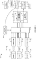
- FIG. 1 schematically illustrates an imaging system 100, such as an ultrasound imaging system, which includes a console 102.
- the console 102 includes a beamformer 104 with transmit circuitry 106 and receive circuitry 108.
- the transmit circuitry 106 and the receive circuitry 108 are not part of the same beamformer.
- the transmit circuitry 106 generates electrical signals which control transducer element phasing and/or time of actuation, which allows for steering and/or focusing an ultrasound beam from predetermined origins and at predetermined angles.
- the receive circuitry 108 processes received ultrasound echoes. For B-mode applications, this has included delaying and summing echoes to produce a sequence of focused, coherent echo samples along focused scanlines of a scanplane.
- the receive circuitry 108 may also be configured to process the scanlines to lower speckle and/or improve specular reflector delineation via spatial compounding and/or perform other processing such as FIR filtering, IIR filtering, etc.
- the beamformer 104 also includes I/O 110, including a plurality of channels (not visible), for conveying the electrical signals and receiving the echoes.
- the imaging system 102 further includes a plurality of connectors 128 1 , 128 2 , ..., 128 L (or connectors 128), where L is an integer equal to or greater than two.
- the connectors 128 each include elements (not visible) such as pins, sockets, etc. that mechanically and/or electrically connect with complementary elements (not visible) of probe connectors 130 1 , 130 2 , ..., 130 L (or probe connectors 130) of ultrasound probes 132 1 , 132 2 , ..., 132 L (or ultrasound probes 132).
- An individual one of the probes 132 may include one or more transducer arrays, each having one or more transducer elements such as 16, 64, 128, 196, 256, and/or other number of transducer elements.
- Individual arrays may include linear, curved, and/or rotary transducer arrays, and the different arrays can be employed individually, simultaneously or in an interleaved manner to acquire data.
- the imaging system 102 further includes a switch 134.
- One side of the switch 134 is in electrical communication with the elements (not visible) of the connectors 128, and the other side of the switch 134 switch is in electrical communication with the I/O 110 of the beamformer 104.
- the I/O 110 includes fewer or the same number of channels (not visible) as the aggregate number of the elements (not visible) of all the connectors 128.
- the I/O 110 may have less, the same number or more channels than there are elements in any one of the individual connectors 128. Where the I/O 110 has fewer channels than there are elements in any one of the individual connectors 128, a fraction of the channels can be used on one connector 128 with the other channels used on one or more other of the connectors 128.
- the switch 134 routes signals between the beamformer 104 and multiple connectors 128 as if the elements (not visible) of the connectors 128 were part of a single connector and the I/O 104 had a number of channels (not visible) equal to that of the elements of the multiple connectors 128 such that any number of probes 132 can be concurrently employed by the console 102, where individual channel (not visible) of the I/O 104 are switched between connector elements (not visible) using fast switching, for example, solid state multiplexers or the like.
- this includes changing the state of the switch 134 during a transmission, so one channel transmits with one element and receives with another element from the same or a different connector 128.
- the state of the switch 134 is changed so that one channel is used to transmit on different elements in the same transmission and/or to receive from different elements during the same transmission, for example, when using neighboring elements in parallel or otherwise. Still other instance are contemplated herein. It is to be appreciated that the connectors 128 can also be operated alternately and/or in an interleaved manner.
- a switch controller 136 transmits signals to the switch 134, which control the switching of the switch 134. Such control can be based on a selected imaging protocol, use of the probes 132 by an operator, and/or otherwise.
- a scan converter 138 converts raw and/or processed echoes to generate data for display, for example, by converting the data to the coordinate system of the display.
- the scan converter 116 can be configured to employ analog and/or digital scan converting techniques.
- a display 140 can be used to present the scan converted data, including multiple images and simultaneous updates of the images.
- a user interface 142 includes various input and/or output devices, for example, to select a data processing and presentation mode, a data acquisition mode (e.g., B-mode), initiate scanning, etc.
- the user interface 142 may include buttons, knobs, a keypad, a touch screen, etc.
- the user interface 122 may also include various types of visual (e.g., LCD, LED, etc.) and/or audible displays.
- a main controller (“controller") 144 includes a processor (not visible) or the like which executes one or more instructions embedded or encoded on computer readable medium such as physical memory 146.
- the processor can additionally or alternatively execute instructions carried by a carrier wave, a signal or other transitory medium.
- the controller 138 can control the beamformer 104, the switch controller 136, the scan converter, and/or the user interface.
- Figure 2 schematically illustrates a non-limiting example of the switch 134 in connection with the I/O 110 of the beamformer 104 and the connectors 128.
- the I/O 110 includes k channels, channel 0 ... channel K-1.
- the connector 128 1 includes N pins (i.e., pin 0 ... N-1)
- the connector 128 2 includes N pins (i.e., pin N ... 2N-1)
- the connector 128 L includes N pins (i.e., pin (M-1)N ... MxN-1).
- the total number of pins is MxN.
- two or more of the connectors 128 may include a different number of pins.
- an electrical pathway 202 alternately electrically connects channel 0 of the I/O 110 to pin 0 of connector 128 1 through a switch 204, to pin N+3 of connector 128 2 through a switch 206, ..., and to pin (M-1))x5 of the connector 128 3 through a switch 208.
- the switch 204 is closed, establishing an electrical connection between channel 0 and pin 0, and switches 206, ..., 208 are open such that no electrical connection is established between channel 0 and pin N+3 or pin (M-1)N+5.
- Other electrical pathways similarly connect other channels of the I/O 110 with other pins of the connector 128 2 ... connector 128 1 .
- the switch controller 136 ( Figure 1 ) sends a signal to the switch 134 which causes switch 204 to open and switch 206 to close such that an electrical connection is established between channel 0 and pin N+3, and no electrical connection exists between channel 0 and pin 0 or channel 0 and pin (M-1)N+5.
- the switch controller 136 ( Figure 1 ) sends a signal to the switch 134 which causes switch 206 to open and switch 208 to close such that an electrical connection is established between channel 0 and pin (M-1)N+5, and no electrical connection exists between channel 0 and pin 0 or channel 0 and pin N+3.
- all the pins of the connector 128 1 are connected to the I/O 110 and a sub-set of the pins of the connector 128 2 are connected to the I/O 110.
- all the pins of the connector 128 2 are connected to the I/O 110 and a sub-set of the pins of the connector 128 1 are connected to the I/O 110.
- some of the pins of one or more of the other connectors 128 are connected to the I/O 110.
- pins of two to M of the connectors 128 can be concurrently connected to the I/O 134 and concurrently employed to concurrently scan.
- Suitable connectors 128 include connectors with pins that generally are inaccessible such as zero insertion force (ZIF) integrated circuit (IC) sockets, low insertion force (LIF) IC sockets, and/or other connectors.
- ZIF zero insertion force
- IC integrated circuit
- LIF low insertion force
- the switch 134 is omitted and the treatment is interrupted so that a second probe can be used to verify presence of the stone.
- Another example is the combination of abdominal and endo scanning where the endo scanning is used to monitor cryo-therapy or HIFU.
- the system 100 can be used for any application in which concurrent use of multiple probes maybe of interest.
- Figure 3 shows an example in which a probe support 302 supports two probes 132 1 and 132 2 at fixed relative positions that are angularly offset from each other by an angle ⁇ .
- the support 302 can support more than two of the probes 132.
- the support 302 is configured to hold the probes 132 such that their image planes 304 and 306 coincide, compounding can be achieved with large compound angles, or a limited degree of tomography can be achieved if the angle ⁇ is large enough that the elements in one of the probes 132 is within sight of the elements of the other of the probes 132.
- the support 302 can extend such that the two probes 132 1 and 132 2 can be angularly oriented with respect to each other (e.g., 180 degrees apart) such that the transducers are face-to-face with a suitable distance there between.
- Tomography can be used to provide velocity and attenuation maps, which are weakly correlated to the scattering information that is used to form B-mode images, so it provides complementary information, and potentially the velocity map can be used to improve the focusing in the B-mode image.
- the support 302 is configured to hold the two probes 132 1 and 132 2 such that their transducers are held with the same orientation but with parallel or almost parallel image planes, flow or motion normal to the image plane can be measured using Doppler techniques or tracking methods.
- the support 302 may be configured to support the probes 132 at designated static positions or one or more of the probes 132 can be manually placed at a position of interest and removeably secured in place.
- a robot, operator, and/or holding device can be used to hold a probe 132 in place.
- Concurrently using multiple probes 132 for spectral Doppler allows for simultaneous Doppler imaging of different organs, which allows the propagation speed of the pulsations to be measured, which is different from measuring flow velocity.
- Concurrent free hand scanning with two or more of the probes 132 can be achieved with having each of the probes 132 track the position of the other probe 132.
- the intersecting image planes can be identified or highlighted using as a dotted line, a dashed line 402 as shown in Figure 4 , and/or other line and/or other indicia.
- a distance between planes can be shown through use of a bar, a circle and/or other indicia, within or outside of the image area. Additionally or alternatively, indicia showing what to do to make the planes coincide as a displacement direction and a rotation can be displayed. For example, as shown in Figure 4 , an arc 404 with an arrow tip 406 can be used to indicate rotation around a transducer axis 408.
- Another option is to show both images in pseudo 3D (e.g., 2D images shown in 3D space) in separate views.
- pseudo 3D e.g., 2D images shown in 3D space
- the location and offset to the shock wave focus can be superimposed on the image from the free hand probe 132.
- the position can be shown as a crosshair used for targeting in combination with an indication of the offset between the image plane and the shock wave focus.
- the probes 132 can be used to estimate their relative positions. This is done by measuring the time of flight from a set of elements on one transducer probe 132 to another set of elements on another transducer probe 132. In a homogeneous medium, this can be achieved through triangulation. In an inhomogeneous medium, the propagation path may not be straight lines and the propagation velocity may not be the same, but due to the principle of reciprocity the path in both directions is the same, and therefore the tracking of a common region of interest in images made with the transducer probes 132 is more accurate than a geometrically accurate tracking system would provide.
- the probes 132 1 and 132 2 can be aligned such that the center scan lines 502 and 504 coincide at a region 506.
- the propagation along the center line is substantially the same in both directions. Therefore, the propagation time to a point on that scan line can be estimated accurately from both transducers as the sum is known. This also holds for the lateral position.
- the triangulation alone cannot align the mutual roll angles. This can be overcome by optimizing the signal strength as it is very dependent on the roll angle.
- the transducers can have a single transducer element that is not in-line with the transducer array, to provide this additional information.
- Figure 6 shows a variation in which a single probe 132 having multiple transducer arrays 602 1 ... 602 j (transducer arrays 602), where j is an integer equal to or greater than one, is connected to a single connector 128.
- the different transducer arrays 602 can be employed as described herein in a similar manner as the different probes 132 in that multiple ones of the transducer arrays 602 can be concurrently employed via suitable switching via the switch 134 between the connector 128 and the I/O 110.
- Figures 1 and 6 are combined in that one or more of the individual probes 132 of Figure 1 can include two or more transducer arrays 602 as shown in Figure 6 .
- the switch 134 switches the channels of the I/O 110 such that two or more probes 132 and/or two or more transducer arrays of two or more probes are concurrently employed.
- Figure 7 illustrates a method for concurrently scanning with multiple transducer probes of an ultrasound console.
- first ultrasound signals are received at a first ultrasound probe connector of the ultrasound console.
- the first ultrasound signals are received from a first ultrasound probe installed in the first ultrasound probe connector.
- second ultrasound signals are received, concurrently with act 702, at a second ultrasound probe connector of the ultrasound console.
- the second ultrasound signals are received from a second ultrasound probe installed in the second ultrasound probe connector.
- the first and second ultrasound signals are concurrently routed, via a switch, to a beamformer of the console.
- the first and second ultrasound signals are processed by the beamformer.
- the methods herein may be implemented by one or more processors executing computer executable instructions stored, encoded, embodied, etc. on computer readable storage medium such as a computer memory, non-transitory storage, etc.
- computer executable instructions are additionally or alternatively stored in transitory or signal medium.
Description
- The following generally relates to ultrasound (US) imaging and more particularly to an US console configured to concurrently scan using multiple probes respectively connected to different probe connectors of the console and/or multiple transducer arrays of a single probe connected to a connector of the console.
- An ultrasound (US) imaging system generally includes a console with a connector(s) configured to receive a complementary connector of an ultrasound probe having a transducer array. The transducer array has been used to transmit ultrasound signals and acquire ultrasound echoes corresponding to a plane (e.g., axial) of an organ(s) and/or structure(s) (e.g., a biopsy needle) in the body. In B-mode imaging, the echoes have been processed to generate scanlines, which have been used to generate a scanplane (or 2D image of the plane), which can be visually presented via a display.
- In order to additionally view a plane in another orientation (e.g., sagittal), the user has to move the probe to the other orientation and perform a scan at the other orientation. In response to moving the probe and scanning in the other orientation, the displayed image in the first orientation is replaced by another image from the other orientation. In order to concurrently utilize the images from both orientations, the clinician has to make a mental image of the first image (i.e., memorize it) and then mentally construct an image based on the mental image and the displayed second image.
- Another approach includes using a second probe connected to a second connector of the console. Unfortunately, ultrasound consoles only scan on one connector at a time. As such, images of different planes are acquired at different times and have to be mentally combined to construct an image. Another approach includes using a biplane probe, which is a probe that includes two arrays angularly arranged with respect to each other to acquire data from different planes (e.g., axial and sagittal planes). With a biplane probe, either both arrays have a reduced set of elements such that the total number of elements is the same as a single array probe or a multiplexer is used to alternately operate the arrays.
-
US-A-5673698 discloses multi-channel ultrasonic diagnosis apparatus having a probe with a vibrator element array or transducer which includes at least two groups of vibrator elements. Connectors are provided for connecting the vibrator elements to respective transmission-reception circuits for transmitting signals from the probe for image processing. -
WO-A-2004/064614 discloses an ultrasonic imaging system having an elongate ultrasonic probe for insertion into a patient. First, second and third arrays of transducer elements are arranged on outer surface of the probe An electronics module is associated with the probe for producing internal images of the patient. - The above matters are addressed by a system according to
claim 1 and a method according to claim 7. In one aspect, the ultrasound imaging system includes a beamformer configured to beamform ultrasound signals. The beamformer includes input/output configured to at least receive ultrasound signals. The ultrasound imaging system further includes a first ultrasound probe connector and a second ultrasound probe connector. The ultrasound imaging system further includes a switch that concurrently routes ultrasound signals concurrently received via the first ultrasound probe connector and the second ultrasound probe connector to the beam former, which processes the ultrasound signals. The input/output comprises a first number of channels. The first connector comprises a first number of pins and the second connector comprises a second number of pins, the first number of channels being less than a summation of the first and second set number of pins. One side of the switch is in electrical communication with elements of the first and second connectors and the other side of the switch is in electrical communication with the input/output of the beamformer. - In another aspect, the method for ultrasound imaging includes routing a first signal between a first transducer array of the first ultrasound probe connected to a first connector and a beamformer through a switch and routing, concurrently with routing the first signal, a second signal between a second transducer array of a second ultrasound probe connected to a second connector of the ultrasound console and the beamformer through the switch. The beamformer has an input/output which comprises a first number of channels and the first connector has a first number of pins. The second connector comprises a second number of pins, the first number of channels being less that a summation of the first and second number of pins, and, one side of the switch is in electrical communication with elements of the first and second connectors and the other side of the switch is in electrical communication with the input/output of the beamformer.
- Those skilled in the art will recognize still other aspects of the present application upon reading and understanding the attached description.
- The application is illustrated by way of example and not limitation in the figures of the accompanying drawings, in which like references indicate similar elements and in which:
-
Figure 1 schematically illustrates an example imaging system configured to concurrently scan with multiple probes respectively connected to different connectors of the console; -
Figure 2 schematically illustrates an example switch of the console configured to switch channels of the console amongst the multiple probes; -
Figure 3 illustrates a support configured to support multiple probes; -
Figure 4 illustrates an image and indicia superimposed thereon showing what to do to make the planes coincide; -
Figure 5 illustrates two probes aligned such that their center scan lines coincide; -
Figure 6 schematically illustrates an example imaging system configured to concurrently scan with multiple transducer arrays of a single probes; and -
Figure 7 illustrates an example for concurrently scanning with multiple transducer probes of an ultrasound console. -
Figure 1 schematically illustrates animaging system 100, such as an ultrasound imaging system, which includes aconsole 102. - The
console 102 includes abeamformer 104 withtransmit circuitry 106 and receivecircuitry 108. In another embodiment, thetransmit circuitry 106 and thereceive circuitry 108 are not part of the same beamformer. Thetransmit circuitry 106 generates electrical signals which control transducer element phasing and/or time of actuation, which allows for steering and/or focusing an ultrasound beam from predetermined origins and at predetermined angles. - The receive
circuitry 108 processes received ultrasound echoes. For B-mode applications, this has included delaying and summing echoes to produce a sequence of focused, coherent echo samples along focused scanlines of a scanplane. The receivecircuitry 108 may also be configured to process the scanlines to lower speckle and/or improve specular reflector delineation via spatial compounding and/or perform other processing such as FIR filtering, IIR filtering, etc. - The
beamformer 104 also includes I/O 110, including a plurality of channels (not visible), for conveying the electrical signals and receiving the echoes. - The
imaging system 102 further includes a plurality ofconnectors connectors 128 each include elements (not visible) such as pins, sockets, etc. that mechanically and/or electrically connect with complementary elements (not visible) ofprobe connectors ultrasound probes - An individual one of the
probes 132 may include one or more transducer arrays, each having one or more transducer elements such as 16, 64, 128, 196, 256, and/or other number of transducer elements. Individual arrays may include linear, curved, and/or rotary transducer arrays, and the different arrays can be employed individually, simultaneously or in an interleaved manner to acquire data. - The
imaging system 102 further includes aswitch 134. One side of theswitch 134 is in electrical communication with the elements (not visible) of theconnectors 128, and the other side of theswitch 134 switch is in electrical communication with the I/O 110 of thebeamformer 104. Generally, the I/O 110 includes fewer or the same number of channels (not visible) as the aggregate number of the elements (not visible) of all theconnectors 128. The I/O 110 may have less, the same number or more channels than there are elements in any one of theindividual connectors 128. Where the I/O 110 has fewer channels than there are elements in any one of theindividual connectors 128, a fraction of the channels can be used on oneconnector 128 with the other channels used on one or more other of theconnectors 128. - As described in greater detail below, the
switch 134 routes signals between thebeamformer 104 andmultiple connectors 128 as if the elements (not visible) of theconnectors 128 were part of a single connector and the I/O 104 had a number of channels (not visible) equal to that of the elements of themultiple connectors 128 such that any number ofprobes 132 can be concurrently employed by theconsole 102, where individual channel (not visible) of the I/O 104 are switched between connector elements (not visible) using fast switching, for example, solid state multiplexers or the like. - In one non-limiting instance, this includes changing the state of the
switch 134 during a transmission, so one channel transmits with one element and receives with another element from the same or adifferent connector 128. In another non-limiting instance, the state of theswitch 134 is changed so that one channel is used to transmit on different elements in the same transmission and/or to receive from different elements during the same transmission, for example, when using neighboring elements in parallel or otherwise. Still other instance are contemplated herein. It is to be appreciated that theconnectors 128 can also be operated alternately and/or in an interleaved manner. - A
switch controller 136 transmits signals to theswitch 134, which control the switching of theswitch 134. Such control can be based on a selected imaging protocol, use of theprobes 132 by an operator, and/or otherwise. - A
scan converter 138 converts raw and/or processed echoes to generate data for display, for example, by converting the data to the coordinate system of the display. The scan converter 116 can be configured to employ analog and/or digital scan converting techniques. Adisplay 140 can be used to present the scan converted data, including multiple images and simultaneous updates of the images. - A
user interface 142 includes various input and/or output devices, for example, to select a data processing and presentation mode, a data acquisition mode (e.g., B-mode), initiate scanning, etc. Theuser interface 142 may include buttons, knobs, a keypad, a touch screen, etc. The user interface 122 may also include various types of visual (e.g., LCD, LED, etc.) and/or audible displays. - A main controller ("controller") 144 includes a processor (not visible) or the like which executes one or more instructions embedded or encoded on computer readable medium such as
physical memory 146. The processor can additionally or alternatively execute instructions carried by a carrier wave, a signal or other transitory medium. Thecontroller 138 can control thebeamformer 104, theswitch controller 136, the scan converter, and/or the user interface. -
Figure 2 schematically illustrates a non-limiting example of theswitch 134 in connection with the I/O 110 of thebeamformer 104 and theconnectors 128. In this example, the I/O 110 includes k channels,channel 0 ... channel K-1. Theconnector 1281 includes N pins (i.e.,pin 0 ... N-1), theconnector 1282 includes N pins (i.e., pin N ... 2N-1), and theconnector 128L includes N pins (i.e., pin (M-1)N ... MxN-1). The total number of pins is MxN. In another embodiment, two or more of theconnectors 128 may include a different number of pins. - As shown, an
electrical pathway 202 alternately electrically connectschannel 0 of the I/O 110 to pin 0 ofconnector 1281 through aswitch 204, to pin N+3 ofconnector 1282 through aswitch 206, ..., and to pin (M-1))x5 of theconnector 1283 through aswitch 208. In the illustrated embodiment, theswitch 204 is closed, establishing an electrical connection betweenchannel 0 andpin 0, and switches 206, ..., 208 are open such that no electrical connection is established betweenchannel 0 and pin N+3 or pin (M-1)N+5. Other electrical pathways similarly connect other channels of the I/O 110 with other pins of theconnector 1282 ...connector 1281. - Where the
next connector 128 to communicate overchannel 0 isconnector 1282, the switch controller 136 (Figure 1 ) sends a signal to theswitch 134 which causes switch 204 to open and switch 206 to close such that an electrical connection is established betweenchannel 0 and pin N+3, and no electrical connection exists betweenchannel 0 andpin 0 orchannel 0 and pin (M-1)N+5. Where thenext connector 128 to communicate overchannel 0 isconnector 1283, the switch controller 136 (Figure 1 ) sends a signal to theswitch 134 which causes switch 206 to open and switch 208 to close such that an electrical connection is established betweenchannel 0 and pin (M-1)N+5, and no electrical connection exists betweenchannel 0 andpin 0 orchannel 0 and pin N+3. - In the illustrated example, all the pins of the
connector 1281 are connected to the I/O 110 and a sub-set of the pins of theconnector 1282 are connected to the I/O 110. In another instance, all the pins of theconnector 1282 are connected to the I/O 110 and a sub-set of the pins of theconnector 1281 are connected to the I/O 110. In yet another instance, some of the pins of one or more of theother connectors 128 are connected to the I/O 110. Generally, through one or more predetermined switching patterns, pins of two to M of theconnectors 128 can be concurrently connected to the I/O 134 and concurrently employed to concurrently scan. -
Suitable connectors 128 include connectors with pins that generally are inaccessible such as zero insertion force (ZIF) integrated circuit (IC) sockets, low insertion force (LIF) IC sockets, and/or other connectors. - There are a number of situations where concurrently employing two or more of the
probes 132 using thesystem 100 can add value to an examination. For example, with lithotripsy, during treatment using a first one of theprobes 132, if the operator is unsure whether there really is a kidney stone at a target point, a second different one of theprobes 132 can be concurrently used to verify the presence of the stone at the target point. - This can save time and improve certainty relative to a configuration in which the
switch 134 is omitted and the treatment is interrupted so that a second probe can be used to verify presence of the stone. Another example is the combination of abdominal and endo scanning where the endo scanning is used to monitor cryo-therapy or HIFU. Generally, thesystem 100 can be used for any application in which concurrent use of multiple probes maybe of interest. -
Figure 3 shows an example in which aprobe support 302 supports twoprobes support 302 can support more than two of theprobes 132. Where thesupport 302 is configured to hold theprobes 132 such that theirimage planes probes 132 is within sight of the elements of the other of theprobes 132. - For tomography, the
support 302 can extend such that the twoprobes - If the axes of the two
probes support 302 is configured to hold the twoprobes - Although the illustrated two
probes probes support 302 may be configured to support theprobes 132 at designated static positions or one or more of theprobes 132 can be manually placed at a position of interest and removeably secured in place. A robot, operator, and/or holding device can be used to hold aprobe 132 in place. - Concurrently using
multiple probes 132 for spectral Doppler allows for simultaneous Doppler imaging of different organs, which allows the propagation speed of the pulsations to be measured, which is different from measuring flow velocity. - Concurrent free hand scanning with two or more of the probes 132 (scanning without using the
support 302 to hold theprobes 132 at fixed relative positions) can be achieved with having each of theprobes 132 track the position of theother probe 132. For visual presentation or display, the intersecting image planes can be identified or highlighted using as a dotted line, a dashedline 402 as shown inFigure 4 , and/or other line and/or other indicia. - Additionally or alternatively, a distance between planes can be shown through use of a bar, a circle and/or other indicia, within or outside of the image area. Additionally or alternatively, indicia showing what to do to make the planes coincide as a displacement direction and a rotation can be displayed. For example, as shown in
Figure 4 , anarc 404 with anarrow tip 406 can be used to indicate rotation around atransducer axis 408. - Another option is to show both images in pseudo 3D (e.g., 2D images shown in 3D space) in separate views. In the case of a tracked freehand transducer for lithotripsy, the location and offset to the shock wave focus can be superimposed on the image from the
free hand probe 132. The position can be shown as a crosshair used for targeting in combination with an indication of the offset between the image plane and the shock wave focus. - If there is no external tracking, the
probes 132 can be used to estimate their relative positions. This is done by measuring the time of flight from a set of elements on onetransducer probe 132 to another set of elements on anothertransducer probe 132. In a homogeneous medium, this can be achieved through triangulation. In an inhomogeneous medium, the propagation path may not be straight lines and the propagation velocity may not be the same, but due to the principle of reciprocity the path in both directions is the same, and therefore the tracking of a common region of interest in images made with the transducer probes 132 is more accurate than a geometrically accurate tracking system would provide. - As an example, and as shown in connection with
Figure 5 , where the twotransducer probes probes center scan lines region 506. The propagation along the center line is substantially the same in both directions. Therefore, the propagation time to a point on that scan line can be estimated accurately from both transducers as the sum is known. This also holds for the lateral position. - If a point is on the center scan line this is true for both transducer probes 1321 and 1322. If the point is not on the center scan line, the two
probes system 100 will to some degree compensate for inhomogeneous velocity in the media between the transducer probes 1321 and 1322 and thereby be more accurate than other methods without tracking. - On two linear array transducers the triangulation alone cannot align the mutual roll angles. This can be overcome by optimizing the signal strength as it is very dependent on the roll angle. Alternatively the transducers can have a single transducer element that is not in-line with the transducer array, to provide this additional information.
- Variations are contemplated.
-
Figure 6 shows a variation in which asingle probe 132 having multiple transducer arrays 6021 ... 602j (transducer arrays 602), where j is an integer equal to or greater than one, is connected to asingle connector 128. In this instance, the different transducer arrays 602 can be employed as described herein in a similar manner as thedifferent probes 132 in that multiple ones of the transducer arrays 602 can be concurrently employed via suitable switching via theswitch 134 between theconnector 128 and the I/O 110. - In another variation, the embodiments of
Figures 1 and6 are combined in that one or more of theindividual probes 132 ofFigure 1 can include two or more transducer arrays 602 as shown inFigure 6 . In this instance, theswitch 134 switches the channels of the I/O 110 such that two ormore probes 132 and/or two or more transducer arrays of two or more probes are concurrently employed. -
Figure 7 illustrates a method for concurrently scanning with multiple transducer probes of an ultrasound console. - At 702, first ultrasound signals are received at a first ultrasound probe connector of the ultrasound console. The first ultrasound signals are received from a first ultrasound probe installed in the first ultrasound probe connector.
- At 704, second ultrasound signals are received, concurrently with act 702, at a second ultrasound probe connector of the ultrasound console. The second ultrasound signals are received from a second ultrasound probe installed in the second ultrasound probe connector.
- At 706, the first and second ultrasound signals are concurrently routed, via a switch, to a beamformer of the console.
- At 708, the first and second ultrasound signals are processed by the beamformer.
- It is to be appreciated that the methods herein may be implemented by one or more processors executing computer executable instructions stored, encoded, embodied, etc. on computer readable storage medium such as a computer memory, non-transitory storage, etc. In another instance, the computer executable instructions are additionally or alternatively stored in transitory or signal medium.
- The application has been described with reference to various embodiments. Modifications and alterations will occur to others upon reading the application. It is intended that the invention be construed as including all such modifications and alterations, including insofar as they come within the scope of the appended claims.
Claims (14)
- An ultrasound imaging system (100), comprising:a first ultrasound probe connector (1281) with a first number of elements;a second ultrasound probe connector (1282) with a second number of elements;a beamformer (104) configured to beamform ultrasound signals, the beamformer including input/output (110) configured to at least receive ultrasound signals from the first and second ultrasound probe connectors (1281, 1282), the input/output having a first number of channels which is less than a summation of the first and second number of elements; anda switch (134) with one side in electrical communication with elements of the first and second ultrasound probe connectors (1281, 1282) and another side thereof in electrical communication with the input/output (110) of the beamformer (104);characterized in that the first and second ultrasound probe connectors (1281, 1282) are configured to receive ultrasound signals concurrently;and in that the switch (134) is configured to route concurrently the concurrently received ultrasound signals from the first ultrasound probe connector (1281) through a fraction of the channels of the first number of channels and from the second ultrasound probe connector (1282) through other channels of the first number of channels, to the beamformer (104) for processing the ultrasound signals.
- The system of claim 1, wherein the ultrasound signals correspond to ultrasound echo signals.
- The system of claim 1 or 2, wherein the switch (134) includes sub-switches (204, 206, 208) between the first and second ultrasound probe connectors (1281, 1282) and a channel (202) of the input/output (110), and further comprising:
a switch controller (136) that controls switching of the sub-switches (204, 206, 208) so that only a single one of the elements of the first and second ultrasound probe connectors (1281, 1282) is connected to a channel (202) at any given moment in time based on a switching algorithm. - The system of claim 3, further comprising:a third ultrasound probe connector (128L);wherein the switch (134) concurrently routes ultrasound signals concurrently received via the first, second and third ultrasound probe connectors (1281, 1282, 128L) to the beamformer (104).
- The system of any one of claims 1 to 4, wherein at least one of the first and second connectors (1281, 1282) comprise one of: zero insertion force integrated circuit sockets and low insertion force integrated sockets connectors.
- The system of any one of claims 1 to 5, wherein the switch (134) is configured to concurrently route a first signal from a first element of a first transducer array of a first probe (1321) connected to the first ultrasound probe connector (1281) and a second signal from a second element of a second transducer array of the first probe (1321) connected to the first ultrasound probe connector (1281) to the beamformer (104).
- A method for ultrasound imaging, the method comprising :receiving ultrasound signals at a first ultrasound probe (1321) connected to a first ultrasound probe connector (1281) having a first number of elements;receiving ultrasound signals at a second ultrasound probe (1322) connected to a second ultrasound probe connector (1282) having a second number of elements;providing electrical communication between one side of a switch (134) and the first number of elements of the first ultrasound probe connector (1281) and the second number of elements of the second ultrasound probe connector (1282);providing electrical communication between another side of the switch (134) and an input/output (110) of a beamformer (104);the input/output (110) comprising a first number of channels which is less than a summation of the first and second number of elements; routing a first signal between the first ultrasound probe connector (1281) and the beamformer (104) through the switch (134); androuting a second signal between the second ultrasound probe connector (1282) and the beamformer (104) through the switch (134); characterized in that the method further comprises:receiving concurrently the first signal from the first ultrasound probe connector (1281) and the second signal from the second ultrasound probe connector (1282); androuting concurrently the first and second signals to the beamformer (104) for processing of the first and second signals, the first signal being routed through a fraction of the channels of the first number of channels and the second signal being routed through other channels of the first number of channels.
- The method of claim 7, wherein the first signal and the second signal correspond to ultrasound echo signals.
- The method of claim 7, wherein the first signal and the second signal correspond to ultrasound transducer element excitation signals.
- The method of claim 7, wherein one of the first and second signals corresponds to an ultrasound transducer element excitation signal, and, the other of the first and second signals corresponds to an ultrasound echo signal.
- The method of any one of claims 7 to 10, further comprising:
routing, concurrently with routing the first signal, a third signal between a third transducer array of a third ultrasound probe (132L) connected to a third connector (128L) and the beamformer (104) through the switch (134). - The method of claim 11, wherein the third signal is routed in place of the second signal.
- The method of any one of claims 7 to 12, further comprising:
electrically connecting at least one channel of the beamformer (104) alternately to either one of the first and second connectors (1281, 1282). - The method of any one of claims 7 to 12, further comprising:
electrically connecting at least one channel of the beamformer (104) alternately to either one of the first and second transducer arrays, wherein a single probe (132) comprises the first and the second transducer arrays.
Applications Claiming Priority (1)
| Application Number | Priority Date | Filing Date | Title |
|---|---|---|---|
| PCT/IB2011/002119 WO2013038217A1 (en) | 2011-09-12 | 2011-09-12 | Ultrasound imaging console |
Publications (2)
| Publication Number | Publication Date |
|---|---|
| EP2756330A1 EP2756330A1 (en) | 2014-07-23 |
| EP2756330B1 true EP2756330B1 (en) | 2018-09-05 |
Family
ID=44903281
Family Applications (1)
| Application Number | Title | Priority Date | Filing Date |
|---|---|---|---|
| EP11773833.6A Active EP2756330B1 (en) | 2011-09-12 | 2011-09-12 | Ultrasound imaging console |
Country Status (4)
| Country | Link |
|---|---|
| US (1) | US9642598B2 (en) |
| EP (1) | EP2756330B1 (en) |
| CN (1) | CN103917889B (en) |
| WO (1) | WO2013038217A1 (en) |
Families Citing this family (18)
| Publication number | Priority date | Publication date | Assignee | Title |
|---|---|---|---|---|
| CA2851839C (en) * | 2011-10-17 | 2020-09-15 | Butterfly Network, Inc. | Transmissive imaging and related apparatus and methods |
| CN104107067A (en) * | 2013-04-16 | 2014-10-22 | 深圳迈瑞生物医疗电子股份有限公司 | Ultrasonic diagnosis equipment and ultrasonic diagnosis method supporting multi-probe synchronous scanning |
| KR102256703B1 (en) | 2013-07-02 | 2021-05-27 | 삼성전자주식회사 | Ultrasonic diagnostic apparatus and operating method for the same |
| WO2016046588A1 (en) * | 2014-09-24 | 2016-03-31 | B-K Medical Aps | Transducer orientation marker |
| JP6986966B2 (en) * | 2014-11-25 | 2021-12-22 | コーニンクレッカ フィリップス エヌ ヴェKoninklijke Philips N.V. | Multi-sensor ultrasonic probe |
| US11129586B1 (en) * | 2015-08-14 | 2021-09-28 | Volumetrics Medical Systems, LLC | Devices, methods, systems, and computer program products for 4-dimensional ultrasound imaging |
| CN107427286B (en) * | 2015-08-31 | 2018-08-28 | 本多电子株式会社 | Ultrasonic image display apparatus and method and the storage medium having program stored therein |
| US20190090842A1 (en) * | 2016-04-19 | 2019-03-28 | Koninklijke Philips N.V. | Acoustic registration of internal and external ultrasound probes |
| CN110312477A (en) * | 2016-09-29 | 2019-10-08 | 精密成像有限公司 | Signal processing approach for supersonic imaging device |
| CN106872986B (en) * | 2017-02-13 | 2019-07-26 | 飞依诺科技(苏州)有限公司 | Ultrasonic imaging method and system supporting double-probe synchronous scanning |
| EP3664717B1 (en) * | 2017-08-10 | 2022-12-14 | Koninklijke Philips N.V. | Connectors for ultrasound imaging system |
| EP3513733A1 (en) | 2018-01-23 | 2019-07-24 | Koninklijke Philips N.V. | Ultrasound imaging apparatus and method |
| EP3632329A1 (en) * | 2018-10-05 | 2020-04-08 | Koninklijke Philips N.V. | Extension cable for an ultrasound system |
| CN110833432B (en) * | 2018-08-15 | 2023-04-07 | 深南电路股份有限公司 | Ultrasonic simulation front-end device and ultrasonic imaging equipment |
| CN109805958B (en) * | 2019-02-22 | 2021-03-16 | 无锡海斯凯尔医学技术有限公司 | Ultrasonic imaging apparatus |
| CN110297436A (en) * | 2019-07-15 | 2019-10-01 | 无锡海斯凯尔医学技术有限公司 | Detection pattern control circuit |
| CN110720948B (en) * | 2019-11-12 | 2021-02-02 | 无锡海斯凯尔医学技术有限公司 | Biological sign detection method based on ultrasonic detection system |
| CN112237444B (en) * | 2020-12-18 | 2021-12-07 | 深圳华声医疗技术股份有限公司 | Control method, control device and medium for ultrasonic imaging system |
Family Cites Families (12)
| Publication number | Priority date | Publication date | Assignee | Title |
|---|---|---|---|---|
| JPH0636795B2 (en) * | 1985-07-23 | 1994-05-18 | 株式会社東芝 | Ultrasonic diagnostic equipment |
| US4819650A (en) | 1987-10-30 | 1989-04-11 | Wayne State University | Biplane probe including centerline highlighting |
| US5673698A (en) * | 1994-04-21 | 1997-10-07 | Hitachi Medical Corporation | Multichannel ultrasonic diagnosis apparatus |
| US6045508A (en) | 1997-02-27 | 2000-04-04 | Acuson Corporation | Ultrasonic probe, system and method for two-dimensional imaging or three-dimensional reconstruction |
| US5897501A (en) * | 1997-05-07 | 1999-04-27 | General Electric Company | Imaging system with multiplexer for controlling a multi-row ultrasonic transducer array |
| US6183419B1 (en) * | 1999-02-01 | 2001-02-06 | General Electric Company | Multiplexed array transducers with improved far-field performance |
| US7520856B2 (en) * | 1999-09-17 | 2009-04-21 | University Of Washington | Image guided high intensity focused ultrasound device for therapy in obstetrics and gynecology |
| EP1594404B1 (en) | 2003-01-23 | 2013-09-11 | 3G Ultrasound, Inc. | Ultrasonic imaging device and system |
| JP2004230033A (en) * | 2003-01-31 | 2004-08-19 | Toshiba Corp | Ultrasonic search unit repolarizing apparatus, ultrasonic probe, and ultrasonograph |
| JP2009066074A (en) * | 2007-09-11 | 2009-04-02 | Olympus Medical Systems Corp | Ultrasonic diagnostic apparatus |
| US9414805B2 (en) | 2008-07-28 | 2016-08-16 | Siemens Medical Solutions Usa, Inc. | Spectral Doppler with multiple spatially distinct gates |
| CN102078204A (en) * | 2009-12-01 | 2011-06-01 | 深圳迈瑞生物医疗电子股份有限公司 | Ultrasonic imaging system and control method thereof and continuous wave Doppler processing device |
-
2011
- 2011-09-12 CN CN201180074093.7A patent/CN103917889B/en active Active
- 2011-09-12 WO PCT/IB2011/002119 patent/WO2013038217A1/en active Application Filing
- 2011-09-12 US US14/344,356 patent/US9642598B2/en active Active
- 2011-09-12 EP EP11773833.6A patent/EP2756330B1/en active Active
Also Published As
| Publication number | Publication date |
|---|---|
| CN103917889A (en) | 2014-07-09 |
| CN103917889B (en) | 2017-07-21 |
| WO2013038217A1 (en) | 2013-03-21 |
| EP2756330A1 (en) | 2014-07-23 |
| US20140343429A1 (en) | 2014-11-20 |
| US9642598B2 (en) | 2017-05-09 |
Similar Documents
| Publication | Publication Date | Title |
|---|---|---|
| EP2756330B1 (en) | Ultrasound imaging console | |
| EP2725984B1 (en) | Object-pose-based initialization of an ultrasound beamformer | |
| EP2566394B1 (en) | Ultrasonic tracking of ultrasound transducer(s) aboard an interventional tool | |
| EP2717772B1 (en) | Three-dimensional needle localization with a two-dimensional imaging probe | |
| US9386964B2 (en) | 3D view of 2D ultrasound images | |
| KR101659723B1 (en) | Multiple aperture ultrasound array alignment fixture | |
| US20060184034A1 (en) | Ultrasonic probe with an integrated display, tracking and pointing devices | |
| CN108474837A (en) | Tracking based on ultrasound | |
| JP6165244B2 (en) | 3D ultrasound guidance for multiple invasive devices | |
| TW201231018A (en) | Concave ultrasound transducers and 3D arrays | |
| WO2009054706A2 (en) | Apparatus and method for creating tissue doppler image using synthetic image | |
| CN106456120A (en) | Multi-purpose instrument guide | |
| US10317510B2 (en) | Apparatus for obtaining trigger signals from ultrasound systems | |
| US20190219693A1 (en) | 3-D US Volume From 2-D Images From Freehand Rotation and/or Translation of Ultrasound Probe | |
| US20160106391A1 (en) | Three Dimensional (3D) Vector Flow Imaging with BiPlane Phased Array Transducer | |
| CN109073751B (en) | Probe, system and method for acoustic registration | |
| EP3711678A1 (en) | Ultrasound diagnostic apparatus and method of controlling the same | |
| WO2019016343A1 (en) | Cross-plane ultrasound imaging system for combined in-plane and out-of-plane instrument guidance | |
| CN114072063B (en) | Ultrasonic three-dimensional imaging method and device | |
| US20220087648A1 (en) | 3-D Endocavity Ultrasound Probe with a Needle Guide | |
| WO2014208803A1 (en) | Ultrasonic probe enabling multiple selections through various focusings and ultrasonic image diagnostic apparatus having same | |
| JP5462679B2 (en) | Ultrasonic diagnostic equipment | |
| WO2001089387A1 (en) | Angle-independent doppler system |
Legal Events
| Date | Code | Title | Description |
|---|---|---|---|
| PUAI | Public reference made under article 153(3) epc to a published international application that has entered the european phase |
Free format text: ORIGINAL CODE: 0009012 |
|
| 17P | Request for examination filed |
Effective date: 20140326 |
|
| AK | Designated contracting states |
Kind code of ref document: A1 Designated state(s): AL AT BE BG CH CY CZ DE DK EE ES FI FR GB GR HR HU IE IS IT LI LT LU LV MC MK MT NL NO PL PT RO RS SE SI SK SM TR |
|
| DAX | Request for extension of the european patent (deleted) | ||
| 17Q | First examination report despatched |
Effective date: 20170130 |
|
| GRAP | Despatch of communication of intention to grant a patent |
Free format text: ORIGINAL CODE: EPIDOSNIGR1 |
|
| INTG | Intention to grant announced |
Effective date: 20180507 |
|
| GRAS | Grant fee paid |
Free format text: ORIGINAL CODE: EPIDOSNIGR3 |
|
| GRAA | (expected) grant |
Free format text: ORIGINAL CODE: 0009210 |
|
| AK | Designated contracting states |
Kind code of ref document: B1 Designated state(s): AL AT BE BG CH CY CZ DE DK EE ES FI FR GB GR HR HU IE IS IT LI LT LU LV MC MK MT NL NO PL PT RO RS SE SI SK SM TR |
|
| REG | Reference to a national code |
Ref country code: GB Ref legal event code: FG4D |
|
| REG | Reference to a national code |
Ref country code: CH Ref legal event code: EP |
|
| REG | Reference to a national code |
Ref country code: AT Ref legal event code: REF Ref document number: 1038471 Country of ref document: AT Kind code of ref document: T Effective date: 20180915 |
|
| REG | Reference to a national code |
Ref country code: IE Ref legal event code: FG4D |
|
| REG | Reference to a national code |
Ref country code: DE Ref legal event code: R096 Ref document number: 602011051805 Country of ref document: DE |
|
| REG | Reference to a national code |
Ref country code: NL Ref legal event code: MP Effective date: 20180905 |
|
| REG | Reference to a national code |
Ref country code: LT Ref legal event code: MG4D |
|
| PG25 | Lapsed in a contracting state [announced via postgrant information from national office to epo] |
Ref country code: FI Free format text: LAPSE BECAUSE OF FAILURE TO SUBMIT A TRANSLATION OF THE DESCRIPTION OR TO PAY THE FEE WITHIN THE PRESCRIBED TIME-LIMIT Effective date: 20180905 Ref country code: LT Free format text: LAPSE BECAUSE OF FAILURE TO SUBMIT A TRANSLATION OF THE DESCRIPTION OR TO PAY THE FEE WITHIN THE PRESCRIBED TIME-LIMIT Effective date: 20180905 Ref country code: RS Free format text: LAPSE BECAUSE OF FAILURE TO SUBMIT A TRANSLATION OF THE DESCRIPTION OR TO PAY THE FEE WITHIN THE PRESCRIBED TIME-LIMIT Effective date: 20180905 Ref country code: NO Free format text: LAPSE BECAUSE OF FAILURE TO SUBMIT A TRANSLATION OF THE DESCRIPTION OR TO PAY THE FEE WITHIN THE PRESCRIBED TIME-LIMIT Effective date: 20181205 Ref country code: GR Free format text: LAPSE BECAUSE OF FAILURE TO SUBMIT A TRANSLATION OF THE DESCRIPTION OR TO PAY THE FEE WITHIN THE PRESCRIBED TIME-LIMIT Effective date: 20181206 Ref country code: SE Free format text: LAPSE BECAUSE OF FAILURE TO SUBMIT A TRANSLATION OF THE DESCRIPTION OR TO PAY THE FEE WITHIN THE PRESCRIBED TIME-LIMIT Effective date: 20180905 Ref country code: BG Free format text: LAPSE BECAUSE OF FAILURE TO SUBMIT A TRANSLATION OF THE DESCRIPTION OR TO PAY THE FEE WITHIN THE PRESCRIBED TIME-LIMIT Effective date: 20181205 |
|
| REG | Reference to a national code |
Ref country code: AT Ref legal event code: MK05 Ref document number: 1038471 Country of ref document: AT Kind code of ref document: T Effective date: 20180905 |
|
| PG25 | Lapsed in a contracting state [announced via postgrant information from national office to epo] |
Ref country code: HR Free format text: LAPSE BECAUSE OF FAILURE TO SUBMIT A TRANSLATION OF THE DESCRIPTION OR TO PAY THE FEE WITHIN THE PRESCRIBED TIME-LIMIT Effective date: 20180905 Ref country code: AL Free format text: LAPSE BECAUSE OF FAILURE TO SUBMIT A TRANSLATION OF THE DESCRIPTION OR TO PAY THE FEE WITHIN THE PRESCRIBED TIME-LIMIT Effective date: 20180905 Ref country code: LV Free format text: LAPSE BECAUSE OF FAILURE TO SUBMIT A TRANSLATION OF THE DESCRIPTION OR TO PAY THE FEE WITHIN THE PRESCRIBED TIME-LIMIT Effective date: 20180905 |
|
| PG25 | Lapsed in a contracting state [announced via postgrant information from national office to epo] |
Ref country code: CZ Free format text: LAPSE BECAUSE OF FAILURE TO SUBMIT A TRANSLATION OF THE DESCRIPTION OR TO PAY THE FEE WITHIN THE PRESCRIBED TIME-LIMIT Effective date: 20180905 Ref country code: ES Free format text: LAPSE BECAUSE OF FAILURE TO SUBMIT A TRANSLATION OF THE DESCRIPTION OR TO PAY THE FEE WITHIN THE PRESCRIBED TIME-LIMIT Effective date: 20180905 Ref country code: IS Free format text: LAPSE BECAUSE OF FAILURE TO SUBMIT A TRANSLATION OF THE DESCRIPTION OR TO PAY THE FEE WITHIN THE PRESCRIBED TIME-LIMIT Effective date: 20190105 Ref country code: EE Free format text: LAPSE BECAUSE OF FAILURE TO SUBMIT A TRANSLATION OF THE DESCRIPTION OR TO PAY THE FEE WITHIN THE PRESCRIBED TIME-LIMIT Effective date: 20180905 Ref country code: PL Free format text: LAPSE BECAUSE OF FAILURE TO SUBMIT A TRANSLATION OF THE DESCRIPTION OR TO PAY THE FEE WITHIN THE PRESCRIBED TIME-LIMIT Effective date: 20180905 Ref country code: NL Free format text: LAPSE BECAUSE OF FAILURE TO SUBMIT A TRANSLATION OF THE DESCRIPTION OR TO PAY THE FEE WITHIN THE PRESCRIBED TIME-LIMIT Effective date: 20180905 Ref country code: IT Free format text: LAPSE BECAUSE OF FAILURE TO SUBMIT A TRANSLATION OF THE DESCRIPTION OR TO PAY THE FEE WITHIN THE PRESCRIBED TIME-LIMIT Effective date: 20180905 Ref country code: RO Free format text: LAPSE BECAUSE OF FAILURE TO SUBMIT A TRANSLATION OF THE DESCRIPTION OR TO PAY THE FEE WITHIN THE PRESCRIBED TIME-LIMIT Effective date: 20180905 Ref country code: AT Free format text: LAPSE BECAUSE OF FAILURE TO SUBMIT A TRANSLATION OF THE DESCRIPTION OR TO PAY THE FEE WITHIN THE PRESCRIBED TIME-LIMIT Effective date: 20180905 |
|
| REG | Reference to a national code |
Ref country code: CH Ref legal event code: PL |
|
| PG25 | Lapsed in a contracting state [announced via postgrant information from national office to epo] |
Ref country code: SM Free format text: LAPSE BECAUSE OF FAILURE TO SUBMIT A TRANSLATION OF THE DESCRIPTION OR TO PAY THE FEE WITHIN THE PRESCRIBED TIME-LIMIT Effective date: 20180905 Ref country code: SK Free format text: LAPSE BECAUSE OF FAILURE TO SUBMIT A TRANSLATION OF THE DESCRIPTION OR TO PAY THE FEE WITHIN THE PRESCRIBED TIME-LIMIT Effective date: 20180905 Ref country code: PT Free format text: LAPSE BECAUSE OF FAILURE TO SUBMIT A TRANSLATION OF THE DESCRIPTION OR TO PAY THE FEE WITHIN THE PRESCRIBED TIME-LIMIT Effective date: 20190105 |
|
| REG | Reference to a national code |
Ref country code: DE Ref legal event code: R097 Ref document number: 602011051805 Country of ref document: DE |
|
| REG | Reference to a national code |
Ref country code: BE Ref legal event code: MM Effective date: 20180930 |
|
| REG | Reference to a national code |
Ref country code: IE Ref legal event code: MM4A |
|
| PG25 | Lapsed in a contracting state [announced via postgrant information from national office to epo] |
Ref country code: LU Free format text: LAPSE BECAUSE OF NON-PAYMENT OF DUE FEES Effective date: 20180912 |
|
| PLBE | No opposition filed within time limit |
Free format text: ORIGINAL CODE: 0009261 |
|
| STAA | Information on the status of an ep patent application or granted ep patent |
Free format text: STATUS: NO OPPOSITION FILED WITHIN TIME LIMIT |
|
| PG25 | Lapsed in a contracting state [announced via postgrant information from national office to epo] |
Ref country code: IE Free format text: LAPSE BECAUSE OF NON-PAYMENT OF DUE FEES Effective date: 20180912 Ref country code: DK Free format text: LAPSE BECAUSE OF FAILURE TO SUBMIT A TRANSLATION OF THE DESCRIPTION OR TO PAY THE FEE WITHIN THE PRESCRIBED TIME-LIMIT Effective date: 20180905 Ref country code: MC Free format text: LAPSE BECAUSE OF FAILURE TO SUBMIT A TRANSLATION OF THE DESCRIPTION OR TO PAY THE FEE WITHIN THE PRESCRIBED TIME-LIMIT Effective date: 20180905 |
|
| 26N | No opposition filed |
Effective date: 20190606 |
|
| GBPC | Gb: european patent ceased through non-payment of renewal fee |
Effective date: 20181205 |
|
| PG25 | Lapsed in a contracting state [announced via postgrant information from national office to epo] |
Ref country code: BE Free format text: LAPSE BECAUSE OF NON-PAYMENT OF DUE FEES Effective date: 20180930 Ref country code: CH Free format text: LAPSE BECAUSE OF NON-PAYMENT OF DUE FEES Effective date: 20180930 Ref country code: LI Free format text: LAPSE BECAUSE OF NON-PAYMENT OF DUE FEES Effective date: 20180930 Ref country code: SI Free format text: LAPSE BECAUSE OF FAILURE TO SUBMIT A TRANSLATION OF THE DESCRIPTION OR TO PAY THE FEE WITHIN THE PRESCRIBED TIME-LIMIT Effective date: 20180905 |
|
| PG25 | Lapsed in a contracting state [announced via postgrant information from national office to epo] |
Ref country code: FR Free format text: LAPSE BECAUSE OF NON-PAYMENT OF DUE FEES Effective date: 20181105 |
|
| PG25 | Lapsed in a contracting state [announced via postgrant information from national office to epo] |
Ref country code: GB Free format text: LAPSE BECAUSE OF NON-PAYMENT OF DUE FEES Effective date: 20181205 |
|
| PG25 | Lapsed in a contracting state [announced via postgrant information from national office to epo] |
Ref country code: MT Free format text: LAPSE BECAUSE OF NON-PAYMENT OF DUE FEES Effective date: 20180912 |
|
| PG25 | Lapsed in a contracting state [announced via postgrant information from national office to epo] |
Ref country code: TR Free format text: LAPSE BECAUSE OF FAILURE TO SUBMIT A TRANSLATION OF THE DESCRIPTION OR TO PAY THE FEE WITHIN THE PRESCRIBED TIME-LIMIT Effective date: 20180905 |
|
| PG25 | Lapsed in a contracting state [announced via postgrant information from national office to epo] |
Ref country code: HU Free format text: LAPSE BECAUSE OF FAILURE TO SUBMIT A TRANSLATION OF THE DESCRIPTION OR TO PAY THE FEE WITHIN THE PRESCRIBED TIME-LIMIT; INVALID AB INITIO Effective date: 20110912 |
|
| PG25 | Lapsed in a contracting state [announced via postgrant information from national office to epo] |
Ref country code: MK Free format text: LAPSE BECAUSE OF NON-PAYMENT OF DUE FEES Effective date: 20180905 Ref country code: CY Free format text: LAPSE BECAUSE OF FAILURE TO SUBMIT A TRANSLATION OF THE DESCRIPTION OR TO PAY THE FEE WITHIN THE PRESCRIBED TIME-LIMIT Effective date: 20180905 |
|
| P01 | Opt-out of the competence of the unified patent court (upc) registered |
Effective date: 20230528 |
|
| PGFP | Annual fee paid to national office [announced via postgrant information from national office to epo] |
Ref country code: DE Payment date: 20230822 Year of fee payment: 13 |