EP2755123A1 - Bildzoomsteuerung mittels Auflagekraftmessung - Google Patents
Bildzoomsteuerung mittels Auflagekraftmessung Download PDFInfo
- Publication number
- EP2755123A1 EP2755123A1 EP13151074.5A EP13151074A EP2755123A1 EP 2755123 A1 EP2755123 A1 EP 2755123A1 EP 13151074 A EP13151074 A EP 13151074A EP 2755123 A1 EP2755123 A1 EP 2755123A1
- Authority
- EP
- European Patent Office
- Prior art keywords
- image
- stylus
- screen
- region
- location
- Prior art date
- Legal status (The legal status is an assumption and is not a legal conclusion. Google has not performed a legal analysis and makes no representation as to the accuracy of the status listed.)
- Withdrawn
Links
Images


Classifications
-
- G—PHYSICS
- G06—COMPUTING; CALCULATING OR COUNTING
- G06F—ELECTRIC DIGITAL DATA PROCESSING
- G06F3/00—Input arrangements for transferring data to be processed into a form capable of being handled by the computer; Output arrangements for transferring data from processing unit to output unit, e.g. interface arrangements
- G06F3/01—Input arrangements or combined input and output arrangements for interaction between user and computer
- G06F3/048—Interaction techniques based on graphical user interfaces [GUI]
- G06F3/0487—Interaction techniques based on graphical user interfaces [GUI] using specific features provided by the input device, e.g. functions controlled by the rotation of a mouse with dual sensing arrangements, or of the nature of the input device, e.g. tap gestures based on pressure sensed by a digitiser
- G06F3/0488—Interaction techniques based on graphical user interfaces [GUI] using specific features provided by the input device, e.g. functions controlled by the rotation of a mouse with dual sensing arrangements, or of the nature of the input device, e.g. tap gestures based on pressure sensed by a digitiser using a touch-screen or digitiser, e.g. input of commands through traced gestures
-
- G—PHYSICS
- G06—COMPUTING; CALCULATING OR COUNTING
- G06F—ELECTRIC DIGITAL DATA PROCESSING
- G06F3/00—Input arrangements for transferring data to be processed into a form capable of being handled by the computer; Output arrangements for transferring data from processing unit to output unit, e.g. interface arrangements
- G06F3/01—Input arrangements or combined input and output arrangements for interaction between user and computer
- G06F3/03—Arrangements for converting the position or the displacement of a member into a coded form
- G06F3/033—Pointing devices displaced or positioned by the user, e.g. mice, trackballs, pens or joysticks; Accessories therefor
- G06F3/0354—Pointing devices displaced or positioned by the user, e.g. mice, trackballs, pens or joysticks; Accessories therefor with detection of 2D relative movements between the device, or an operating part thereof, and a plane or surface, e.g. 2D mice, trackballs, pens or pucks
- G06F3/03545—Pens or stylus
-
- G—PHYSICS
- G06—COMPUTING; CALCULATING OR COUNTING
- G06F—ELECTRIC DIGITAL DATA PROCESSING
- G06F3/00—Input arrangements for transferring data to be processed into a form capable of being handled by the computer; Output arrangements for transferring data from processing unit to output unit, e.g. interface arrangements
- G06F3/01—Input arrangements or combined input and output arrangements for interaction between user and computer
- G06F3/03—Arrangements for converting the position or the displacement of a member into a coded form
- G06F3/033—Pointing devices displaced or positioned by the user, e.g. mice, trackballs, pens or joysticks; Accessories therefor
- G06F3/038—Control and interface arrangements therefor, e.g. drivers or device-embedded control circuitry
- G06F3/0383—Signal control means within the pointing device
-
- G—PHYSICS
- G06—COMPUTING; CALCULATING OR COUNTING
- G06F—ELECTRIC DIGITAL DATA PROCESSING
- G06F2203/00—Indexing scheme relating to G06F3/00 - G06F3/048
- G06F2203/048—Indexing scheme relating to G06F3/048
- G06F2203/04805—Virtual magnifying lens, i.e. window or frame movable on top of displayed information to enlarge it for better reading or selection
-
- G—PHYSICS
- G06—COMPUTING; CALCULATING OR COUNTING
- G06F—ELECTRIC DIGITAL DATA PROCESSING
- G06F2203/00—Indexing scheme relating to G06F3/00 - G06F3/048
- G06F2203/048—Indexing scheme relating to G06F3/048
- G06F2203/04806—Zoom, i.e. interaction techniques or interactors for controlling the zooming operation
Definitions
- Electronic devices may have relatively small display screens by which a user must access graphical user interfaces, visual media, drawing applications, and other applications and features provided by a device.
- Handheld smart-phones are an example of electronic devices that have a relatively small display screen.
- Some display screens have a "zoom" capability that allows a user to enlarge the image shown on the screen.
- the amount of zoom is controlled by user interaction with a control element, such as a slider, menu or pressure-sensitive control, shown on the screen.
- the zoom feature can be employed to enlarge the entire displayed image, so that a portion of the periphery of the images is lost from view.
- FIG. 1 is a diagram of a system for displaying images, in accordance with exemplary embodiments of the present disclosure
- FIG. 2 is a block diagram of an exemplary system for displaying images, in accordance with exemplary embodiments of the present disclosure
- FIG's 3 and 4 are graphs showing illustrative image modification functions, in accordance with exemplary embodiments of the present disclosure
- FIG's 5-8 are diagrammatic representations of a screen of an electronic device illustrating image zoom control using a sensed stylus force, in accordance with exemplary embodiments of the present disclosure.
- FIG. 9 is a flow chart of a method for displaying an image on a screen of an electronic device, in accordance with exemplary embodiments of the disclosure.
- FIG. 1 is a diagram of system 100 for displaying images, in accordance with exemplary embodiments of the present disclosure.
- the system 100 includes a stylus pointing device 102.
- the tip 104 of the stylus indicates a location on a screen 108 of an electronic device 110, from which a modification region 106 is determined.
- the location of the tip 104 of the stylus may be sensed by any of a number of techniques known to those in the art.
- the electronic device may be a handheld device, such as a smart-phone, personal digital assistant, or portable media player, for example; a portable device, such as a laptop computer or tablet computer, for example; or a desktop device, such as a desktop computer.
- operation of stylus 102 is used to modify an image displayed in the modification region 106.
- the image displayed in the modification region 106 may be enlarged by an amount dependent upon the contact force between the stylus 102 and the screen 108.
- the modification region 106 comprises a circle, but regions of other shapes, such as rectangular or elliptical, for instance, may be used. The shape may be defined by the user.
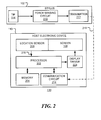
- FIG. 2 is a block diagram of an exemplary system 100 for displaying images, in accordance with exemplary embodiments of the present disclosure.
- An electronic device 110 has a screen 108, a memory 204 operable to store images and instructions for a processor 202.
- the processor 202 is operatively coupled to the memory 204 and, via display driver 206, to the screen 108.
- the processor 202 is responsive to a stylus location input 218 from a stylus location sensor 208.
- the system 100 also includes a stylus 102.
- the stylus 102 has a tip 104 coupled to a force sensing circuit 210.
- the force sensing circuit 210 provides a stylus force signal to a wired or wireless transmitter 212 that, in turn, sends a stylus force input 216 to a communications circuit 214 of the electronic device 110.
- the processor 110 is responsive to the stylus force input 216 that, in this embodiment, is received via a communication circuit 214.
- the stylus contact force may be sensed by the electronic device, by the stylus, or by a combination thereof, and the stylus location may be sensed by the electronic device, the stylus, or a combination thereof.
- the processor 202 modifies the part of an original image associated with a region of the screen 108 (determined from the stylus location input), and passes the modified image to display driver 206 for display on the screen 108.
- the modified image is dependent upon the original image and the modification is dependent upon the stylus force input 216.
- the modification region of the screen is determined at least in part by the stylus location, but may also depend upon the stylus force input 216.
- the modified image may be an enlarged image, for example, for which the degree of enlargement is dependent upon the stylus force input.
- the degree of enlargement at a position in the first image may also be dependent upon the distance of the position from the stylus location indicated by the stylus location input 218.
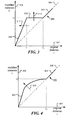
- FIG. 3 is a graph showing an illustrative relationship 300 between a position in an original image and a corresponding position in a modified image. That is, a pixel that would have been displayed at the original position is instead displayed at the corresponding position in the modified image.
- the modification region comprises a circle of radius r 2 centered at the current stylus location.
- the horizontal axis 302 shows the distance r of a position in the original image (relative to the stylus location), while the vertical axis 304 shows the distance r' of a corresponding position in the modified image (again, relative to the stylus location).
- the relationship depicted by the broken line 306, results in an unmodified image.
- the line 300 which is composed of line segments 308, 310 and 312, indicates the relationship between the original image positions and the modified image positions for a particular stylus force value.
- the slope of the line segment 308 is greater than one, indicating that points in the original image within a circle of radius r 1 have been enlarged or magnified to fill the region within a circle of radius r 2 .
- the relation may change.
- the line segment 314 may move in the direction of arrow 314. This increases the magnification or zoom of the region around the stylus location.
- the line segment 310 may move in the direction indicated by arrow 316 as the stylus force increases.
- the modified region which in this example is the region within a circle of radius r 2 centered at the stylus location. That is, the magnified region gets bigger as the user presses harder with the stylus on the device screen.
- the line segment 312 lies on the broken line 306, indicating that image points outside of the region are not modified.
- the region of the original image between radius r 1 and radius r 2 , where the line segment 310 has zero slope, is not displayed.
- FIG. 4 is a graph showing a further illustrative relationship 300 between a position in an original image and a position in a modified image.
- the modification region again comprises a circle of radius r 2 centered at the current stylus location on the screen.
- the line 300 which is composed of line segments 402 and 404, indicates the relationship between the original image positions and the modified image positions for a particular stylus force value.
- the line segment 402 lies above and to the left of the broken line 306, indicating that corresponding points in the original image have been moved outwards from their original positions, relative to the stylus location.
- the relation may change as indicated by the arrow 406. This increases the magnification or zoom of the region closest to the stylus location. In this example, all the original image is displayed, but with varying degrees of magnification or contraction.
- an element in the modified image is obtained by determining an original position of the element relative to the stylus location, and determining a modified position of the element as a function of the original position and the stylus force input.
- the element may be a pixel, for example.
- the origin of the coordinate system is taken to be the stylus location.
- ⁇ denotes the directional angle of the position from the stylus location.
- the function m may be defined in parametric form or a lookup table, for example. Equation (1) describes a radial distortion of the original image. Angular distortion may also be included, if desired.
- the radius r 2 may also be a function of the stylus force F.
- equations (1) and (2) shown in FIG. 3
- the function shown in FIG. 4 is a non-linear function of the radial position.
- FIG. 5 is a diagrammatic representation of a screen 108 of an electronic device.
- an original image comprising a number of square objects, such as 502, 504 and 506, are displayed on the screen 108. It is assumed that the stylus is pointed at the square object 502.
- the region 106 lies within a circle of radius r 1 , such as shown in FIG. 3 .
- the region 106 may be indicated by a translucent overlay, by a circle or not indicated.
- the image within the region 106 is enlarged or magnified as depicted by region 602 in FIG. 6 .
- FIG. 6 shows a modified region 602, comprising a circle of radius r 2 , such as shown in FIG. 3 ), in which the original image is enlarged.
- the original image outside of region 602 is unchanged.
- the object 502 is enlarged to become object 604.
- the degree of enlargement is dependent upon the force applied to the stylus, as discussed with reference to FIG. 3 above. Elements 504 and 506 are partially obscured. If the stylus is moved, the enlarged region moves to track the stylus location. This is illustrated in FIG. 7 .
- FIG. 7 the stylus location has been moved towards the left of the screen 108, resulting in a modified region 702.
- portions of the objects 502 and 504 (shown in FIG. 5 ) have been magnified.
- a portion of object 502 is shown as element 704 and a portion of the object 504 is shown as element 706.
- the level of magnification achieved is dependent upon the stylus force applied to the stylus.
- the magnification increases at the same rate as stylus force increases.
- magnification is only decreased slowly, or after a wait period, when stylus force is reduced. This enables the magnified region to be moved across the screen without the need to retain a high stylus force.
- the modification to the image is dependent upon a stylus force input at one or more prior times.
- FIG. 8 is shows a modified region 802, comprising a circle of radius r 2 , say, in which the original image is enlarged.
- the original image outside of region 802 is unchanged.
- the degree of enlargement is dependent upon the force applied to the stylus.
- the modification is a non-linear function as discussed with reference to FIG. 4 above. Thus, none of the original image is obscured.
- the portion of the image inside the region 802 is modified dependent upon the stylus force and dependent upon the distance of each element of the image from the stylus location.
- the object 502 (shown in FIG. 5 ) is enlarged to become object 804.
- the right side of object 504 is enlarged, as is the left side of object 506. Since the amount of magnification varies with position, at least some of the magnified image is distorted. If the initial portion of the line segment 402 in FIG. 4 is linear, the central portion of region 802 will not be distorted. An advantage of this approach is that none of the original image is obscured.
- the approach disclosed above provides a stylus-based electronic device with the ability to zoom in and out on a portion of the screen.
- a user can point a stylus pen at an area of the screen and, by varying the force or pressure applied to the stylus, zoom-in and zoom-out just that portion of the screen.
- the force may be sensed by a force sensor incorporated into the stylus.
- the sensed force is communicated to the host electronic device and is translated into a zoom area that gets bigger and/or more magnified the harder you press.
- the magnified area of the screen follows the location of the stylus, creating an effect similar to a magnifying glass.
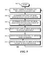
- FIG. 9 is a flow chart of a method 900 for displaying an image on a screen of an electronic device, in accordance with embodiments of the disclosure.
- a region of the screen is selected at block 904 in response to a stylus location input.
- the region includes the stylus location.
- a first part of the image, associated with the selected region is determined.
- a second part of the image, associated with a region of the screen outside of the selected region is determined.
- the first part of the image is modified, in response to a stylus force input, to provide a modified first part of the image.
- the modified first part of the image is displayed in the selected region of the screen.
- the second, unmodified, part of the image is displayed on the screen outside of the selected region of the screen.
- Flow then returns to block 904, where the stylus location is updated to allow the selected region to track motion of the stylus across the screen.
- the first part of the image may be modified by enlarging it.
- the first part of the image may be modified by a radial distortion relative to the stylus location and dependent upon the stylus force input. While the blocks of the flow chart are shown in order, some of the blocks may be performed together in time. Consider, for example, blocks 912 and 914. As a practical matter, the modified first part of the image and the second part of the image are displayed on the screen at the same time.
- any module or component disclosed herein that executes instructions may include or otherwise have access to non-transient and tangible computer readable media such as storage media, computer storage media, or data storage devices (removable or non-removable) such as, for example, magnetic disks, optical disks, or tape data storage.
- Computer storage media may include volatile and non-volatile, removable and non-removable media implemented in any method or technology for storage of information, such as computer readable instructions, data structures, program modules, or other data.
- Examples of computer storage media include RAM, ROM, EEPROM, flash memory or other memory technology, CD-ROM, digital versatile disks (DVD) or other optical storage, magnetic cassettes, magnetic tape, magnetic disk storage or other magnetic storage devices, or any other medium which can be used to store the desired information and which can be accessed by an application, module, or both. Any such computer storage media may be part of the server, any component of or related to the network, backend, etc., or accessible or connectable thereto. Any application or module herein described may be implemented using computer readable/executable instructions that may be stored or otherwise held by such computer readable media.
Priority Applications (1)
| Application Number | Priority Date | Filing Date | Title |
|---|---|---|---|
| EP13151074.5A EP2755123A1 (de) | 2013-01-11 | 2013-01-11 | Bildzoomsteuerung mittels Auflagekraftmessung |
Applications Claiming Priority (1)
| Application Number | Priority Date | Filing Date | Title |
|---|---|---|---|
| EP13151074.5A EP2755123A1 (de) | 2013-01-11 | 2013-01-11 | Bildzoomsteuerung mittels Auflagekraftmessung |
Publications (1)
| Publication Number | Publication Date |
|---|---|
| EP2755123A1 true EP2755123A1 (de) | 2014-07-16 |
Family
ID=47603291
Family Applications (1)
| Application Number | Title | Priority Date | Filing Date |
|---|---|---|---|
| EP13151074.5A Withdrawn EP2755123A1 (de) | 2013-01-11 | 2013-01-11 | Bildzoomsteuerung mittels Auflagekraftmessung |
Country Status (1)
| Country | Link |
|---|---|
| EP (1) | EP2755123A1 (de) |
Cited By (1)
| Publication number | Priority date | Publication date | Assignee | Title |
|---|---|---|---|---|
| WO2017036776A1 (de) * | 2015-08-31 | 2017-03-09 | BSH Hausgeräte GmbH | Berührungsempfindliche bedienanzeige sowie verfahren zum verbessern einer bedienbarkeit einer skala einer solchen bedienanzeige |
Citations (6)
| Publication number | Priority date | Publication date | Assignee | Title |
|---|---|---|---|---|
| US20070097151A1 (en) * | 2006-04-07 | 2007-05-03 | Outland Research, Llc | Behind-screen zoom for handheld computing devices |
| US20090295830A1 (en) * | 2005-12-07 | 2009-12-03 | 3Dlabs Inc., Ltd. | User interface for inspection of photographs |
| US20100051356A1 (en) * | 2008-08-25 | 2010-03-04 | N-Trig Ltd. | Pressure sensitive stylus for a digitizer |
| US20100090964A1 (en) * | 2008-10-10 | 2010-04-15 | At&T Intellectual Property I, L.P. | Augmented i/o for limited form factor user-interfaces |
| US20110057886A1 (en) * | 2009-09-10 | 2011-03-10 | Oliver Ng | Dynamic sizing of identifier on a touch-sensitive display |
| EP2530677A2 (de) * | 2011-05-31 | 2012-12-05 | Samsung Electronics Co., Ltd. | Verfahren und Vorrichtung zur Steuerung einer Anzeige von Multimediainhalt unter Verwendung einer Timeline-basierten Schnittstelle |
-
2013
- 2013-01-11 EP EP13151074.5A patent/EP2755123A1/de not_active Withdrawn
Patent Citations (6)
| Publication number | Priority date | Publication date | Assignee | Title |
|---|---|---|---|---|
| US20090295830A1 (en) * | 2005-12-07 | 2009-12-03 | 3Dlabs Inc., Ltd. | User interface for inspection of photographs |
| US20070097151A1 (en) * | 2006-04-07 | 2007-05-03 | Outland Research, Llc | Behind-screen zoom for handheld computing devices |
| US20100051356A1 (en) * | 2008-08-25 | 2010-03-04 | N-Trig Ltd. | Pressure sensitive stylus for a digitizer |
| US20100090964A1 (en) * | 2008-10-10 | 2010-04-15 | At&T Intellectual Property I, L.P. | Augmented i/o for limited form factor user-interfaces |
| US20110057886A1 (en) * | 2009-09-10 | 2011-03-10 | Oliver Ng | Dynamic sizing of identifier on a touch-sensitive display |
| EP2530677A2 (de) * | 2011-05-31 | 2012-12-05 | Samsung Electronics Co., Ltd. | Verfahren und Vorrichtung zur Steuerung einer Anzeige von Multimediainhalt unter Verwendung einer Timeline-basierten Schnittstelle |
Cited By (1)
| Publication number | Priority date | Publication date | Assignee | Title |
|---|---|---|---|---|
| WO2017036776A1 (de) * | 2015-08-31 | 2017-03-09 | BSH Hausgeräte GmbH | Berührungsempfindliche bedienanzeige sowie verfahren zum verbessern einer bedienbarkeit einer skala einer solchen bedienanzeige |
Similar Documents
| Publication | Publication Date | Title |
|---|---|---|
| US10409366B2 (en) | Method and apparatus for controlling display of digital content using eye movement | |
| US20130215018A1 (en) | Touch position locating method, text selecting method, device, and electronic equipment | |
| US10969949B2 (en) | Information display device, information display method and information display program | |
| US8350872B2 (en) | Graphical user interfaces and occlusion prevention for fisheye lenses with line segment foci | |
| US9626077B2 (en) | Method, system for updating dynamic map-type graphic interface and electronic device using the same | |
| US9395910B2 (en) | Invoking zoom on touch-screen devices | |
| KR20150034255A (ko) | 3d 상호작용을 위한 멀티터치 제스처 인식의 명확화 | |
| US8624928B2 (en) | System and method for magnifying a webpage in an electronic device | |
| US11003340B2 (en) | Display device | |
| CN108733296B (zh) | 书写笔迹的擦除方法、装置和设备 | |
| US9983764B2 (en) | Method, electronic device, and non-transitory storage medium for adjusting icons | |
| CN106897321B (zh) | 显示地图数据的方法及装置 | |
| US20140198081A1 (en) | Image zoom control using stylus force sensing | |
| EP2755123A1 (de) | Bildzoomsteuerung mittels Auflagekraftmessung | |
| US20150281585A1 (en) | Apparatus Responsive To At Least Zoom-In User Input, A Method And A Computer Program | |
| US10636117B2 (en) | Distortion viewing with improved focus targeting | |
| CN107766703A (zh) | 水印添加处理方法、装置及客户端 | |
| US20130321470A1 (en) | Apparatus and method for viewing an image that is larger than an area of a display device | |
| US9146666B2 (en) | Touch sensor navigation | |
| WO2012120978A1 (ja) | 表示方法、表示装置およびプログラム | |
| CN103941978A (zh) | 一种控件内容显示方法 | |
| CN110058751B (zh) | 选择电子文档内容的方法及装置 | |
| US20150277705A1 (en) | Graphical user interface user input technique for choosing and combining digital images as video | |
| US7986322B1 (en) | Parallax compensation | |
| KR101730381B1 (ko) | 문맥 정보에 기초하여 스크롤을 제어하기 위한 방법, 시스템 및 비일시성의 컴퓨터 판독 가능한 기록 매체 |
Legal Events
| Date | Code | Title | Description |
|---|---|---|---|
| PUAI | Public reference made under article 153(3) epc to a published international application that has entered the european phase |
Free format text: ORIGINAL CODE: 0009012 |
|
| 17P | Request for examination filed |
Effective date: 20130111 |
|
| AK | Designated contracting states |
Kind code of ref document: A1 Designated state(s): AL AT BE BG CH CY CZ DE DK EE ES FI FR GB GR HR HU IE IS IT LI LT LU LV MC MK MT NL NO PL PT RO RS SE SI SK SM TR |
|
| AX | Request for extension of the european patent |
Extension state: BA ME |
|
| STAA | Information on the status of an ep patent application or granted ep patent |
Free format text: STATUS: THE APPLICATION HAS BEEN WITHDRAWN |
|
| 18W | Application withdrawn |
Effective date: 20160822 |