EP2755018B2 - Device and method for the non-contact detection of red tissue structures and assembly for detaching a strip of red tissue structures - Google Patents
Device and method for the non-contact detection of red tissue structures and assembly for detaching a strip of red tissue structures Download PDFInfo
- Publication number
- EP2755018B2 EP2755018B2 EP13151359.0A EP13151359A EP2755018B2 EP 2755018 B2 EP2755018 B2 EP 2755018B2 EP 13151359 A EP13151359 A EP 13151359A EP 2755018 B2 EP2755018 B2 EP 2755018B2
- Authority
- EP
- European Patent Office
- Prior art keywords
- product
- light
- tissue structures
- designed
- light source
- Prior art date
- Legal status (The legal status is an assumption and is not a legal conclusion. Google has not performed a legal analysis and makes no representation as to the accuracy of the status listed.)
- Active
Links
- 238000000034 method Methods 0.000 title claims description 23
- 238000001514 detection method Methods 0.000 title description 50
- 230000003287 optical effect Effects 0.000 claims description 21
- 241001465754 Metazoa Species 0.000 claims description 4
- 238000007654 immersion Methods 0.000 claims description 4
- 238000007689 inspection Methods 0.000 claims description 4
- 238000005286 illumination Methods 0.000 claims description 2
- 210000001519 tissue Anatomy 0.000 description 55
- 210000003205 muscle Anatomy 0.000 description 18
- 239000004744 fabric Substances 0.000 description 12
- 235000013372 meat Nutrition 0.000 description 12
- 230000008901 benefit Effects 0.000 description 10
- 238000011156 evaluation Methods 0.000 description 7
- 238000012545 processing Methods 0.000 description 7
- 241000251468 Actinopterygii Species 0.000 description 6
- 239000010868 animal carcass Substances 0.000 description 6
- 230000004907 flux Effects 0.000 description 4
- 238000010521 absorption reaction Methods 0.000 description 3
- 239000008280 blood Substances 0.000 description 2
- 210000004369 blood Anatomy 0.000 description 2
- 230000036770 blood supply Effects 0.000 description 2
- 230000004069 differentiation Effects 0.000 description 2
- 235000013622 meat product Nutrition 0.000 description 2
- 230000005855 radiation Effects 0.000 description 2
- 238000001454 recorded image Methods 0.000 description 2
- 241000962514 Alosa chrysochloris Species 0.000 description 1
- 210000000683 abdominal cavity Anatomy 0.000 description 1
- 238000000149 argon plasma sintering Methods 0.000 description 1
- 230000002238 attenuated effect Effects 0.000 description 1
- 230000017531 blood circulation Effects 0.000 description 1
- 210000004204 blood vessel Anatomy 0.000 description 1
- 235000019688 fish Nutrition 0.000 description 1
- 235000013332 fish product Nutrition 0.000 description 1
- 238000012994 industrial processing Methods 0.000 description 1
- 230000035699 permeability Effects 0.000 description 1
- 238000012805 post-processing Methods 0.000 description 1
- 244000144977 poultry Species 0.000 description 1
- 235000013594 poultry meat Nutrition 0.000 description 1
- 235000013613 poultry product Nutrition 0.000 description 1
- 230000008569 process Effects 0.000 description 1
- 230000035945 sensitivity Effects 0.000 description 1
- 238000000926 separation method Methods 0.000 description 1
- 238000003307 slaughter Methods 0.000 description 1
- 230000007704 transition Effects 0.000 description 1
- 238000009966 trimming Methods 0.000 description 1
Images

Classifications
-
- A—HUMAN NECESSITIES
- A22—BUTCHERING; MEAT TREATMENT; PROCESSING POULTRY OR FISH
- A22C—PROCESSING MEAT, POULTRY, OR FISH
- A22C17/00—Other devices for processing meat or bones
- A22C17/0073—Other devices for processing meat or bones using visual recognition, X-rays, ultrasounds, or other contactless means to determine quality or size of portioned meat
- A22C17/008—Other devices for processing meat or bones using visual recognition, X-rays, ultrasounds, or other contactless means to determine quality or size of portioned meat for measuring quality, e.g. to determine further processing
-
- A—HUMAN NECESSITIES
- A22—BUTCHERING; MEAT TREATMENT; PROCESSING POULTRY OR FISH
- A22C—PROCESSING MEAT, POULTRY, OR FISH
- A22C21/00—Processing poultry
- A22C21/0023—Dividing poultry
- A22C21/003—Filleting poultry, i.e. extracting, cutting or shaping poultry fillets
-
- A—HUMAN NECESSITIES
- A22—BUTCHERING; MEAT TREATMENT; PROCESSING POULTRY OR FISH
- A22C—PROCESSING MEAT, POULTRY, OR FISH
- A22C25/00—Processing fish ; Curing of fish; Stunning of fish by electric current; Investigating fish by optical means
- A22C25/04—Sorting fish; Separating ice from fish packed in ice
-
- A—HUMAN NECESSITIES
- A22—BUTCHERING; MEAT TREATMENT; PROCESSING POULTRY OR FISH
- A22C—PROCESSING MEAT, POULTRY, OR FISH
- A22C25/00—Processing fish ; Curing of fish; Stunning of fish by electric current; Investigating fish by optical means
- A22C25/18—Cutting fish into portions
-
- G—PHYSICS
- G01—MEASURING; TESTING
- G01B—MEASURING LENGTH, THICKNESS OR SIMILAR LINEAR DIMENSIONS; MEASURING ANGLES; MEASURING AREAS; MEASURING IRREGULARITIES OF SURFACES OR CONTOURS
- G01B11/00—Measuring arrangements characterised by the use of optical techniques
- G01B11/24—Measuring arrangements characterised by the use of optical techniques for measuring contours or curvatures
- G01B11/25—Measuring arrangements characterised by the use of optical techniques for measuring contours or curvatures by projecting a pattern, e.g. one or more lines, moiré fringes on the object
- G01B11/2518—Projection by scanning of the object
-
- G—PHYSICS
- G01—MEASURING; TESTING
- G01N—INVESTIGATING OR ANALYSING MATERIALS BY DETERMINING THEIR CHEMICAL OR PHYSICAL PROPERTIES
- G01N21/00—Investigating or analysing materials by the use of optical means, i.e. using sub-millimetre waves, infrared, visible or ultraviolet light
- G01N21/17—Systems in which incident light is modified in accordance with the properties of the material investigated
- G01N21/25—Colour; Spectral properties, i.e. comparison of effect of material on the light at two or more different wavelengths or wavelength bands
- G01N21/31—Investigating relative effect of material at wavelengths characteristic of specific elements or molecules, e.g. atomic absorption spectrometry
- G01N21/35—Investigating relative effect of material at wavelengths characteristic of specific elements or molecules, e.g. atomic absorption spectrometry using infrared light
- G01N21/3563—Investigating relative effect of material at wavelengths characteristic of specific elements or molecules, e.g. atomic absorption spectrometry using infrared light for analysing solids; Preparation of samples therefor
-
- G—PHYSICS
- G01—MEASURING; TESTING
- G01N—INVESTIGATING OR ANALYSING MATERIALS BY DETERMINING THEIR CHEMICAL OR PHYSICAL PROPERTIES
- G01N21/00—Investigating or analysing materials by the use of optical means, i.e. using sub-millimetre waves, infrared, visible or ultraviolet light
- G01N21/84—Systems specially adapted for particular applications
- G01N21/88—Investigating the presence of flaws or contamination
- G01N21/94—Investigating contamination, e.g. dust
-
- G—PHYSICS
- G01—MEASURING; TESTING
- G01N—INVESTIGATING OR ANALYSING MATERIALS BY DETERMINING THEIR CHEMICAL OR PHYSICAL PROPERTIES
- G01N33/00—Investigating or analysing materials by specific methods not covered by groups G01N1/00 - G01N31/00
- G01N33/02—Food
- G01N33/12—Meat; fish
-
- G—PHYSICS
- G01—MEASURING; TESTING
- G01N—INVESTIGATING OR ANALYSING MATERIALS BY DETERMINING THEIR CHEMICAL OR PHYSICAL PROPERTIES
- G01N21/00—Investigating or analysing materials by the use of optical means, i.e. using sub-millimetre waves, infrared, visible or ultraviolet light
- G01N21/84—Systems specially adapted for particular applications
- G01N2021/845—Objects on a conveyor
-
- G—PHYSICS
- G01—MEASURING; TESTING
- G01N—INVESTIGATING OR ANALYSING MATERIALS BY DETERMINING THEIR CHEMICAL OR PHYSICAL PROPERTIES
- G01N2201/00—Features of devices classified in G01N21/00
- G01N2201/06—Illumination; Optics
- G01N2201/061—Sources
- G01N2201/06113—Coherent sources; lasers
Definitions
- the present invention relates to a device for the non-contact detection of red tissue structures in products from slaughtered animal carcasses.
- the present invention further relates to a method for non-contact detection of red tissue structures in products of slaughtered animal carcasses and an arrangement for releasing a strip of red tissue structures from products of slaughtered animal carcasses.
- Such devices, methods and arrangements are used in various areas of the industrial processing of slaughtered animal carcasses, for example in the processing of fish, meat or poultry products, in particular in the processing of fish fillets, for example in the processing of tuna, e.g. skipjacks.
- the red tissue structures are usually highly perfused tissue types that are visually different from other tissues.
- the red tissue structures mentioned include highly perfused muscle meat.
- the US$3,800,363 discloses an apparatus and method for slaughtering tuna.
- the US 5,324,228 deals with a method and apparatus for trimming fat in meat products.
- the object of the present invention to propose a device which ensures reliable detection and differentiation of different types of tissue in the products that are perfused with blood. Furthermore, the task is to propose an appropriate procedure. Furthermore, the task is to propose an arrangement that reliably ensures the automatic removal of certain types of tissue from the products.
- the object is achieved by a device having the features of claim 1.
- the infrared light used is absorbed more strongly in the product in the areas of the red tissue structures than is the case in the other tissue components of the product.
- the difference is particularly large between the red tissue structures and the rest of the tissue, so that the areas with the red tissue structures are detected precisely and with high reliability.
- the present invention is therefore fundamentally suitable for detecting red tissue structures, for example tissues with a high blood supply, in particular red muscle meat. It is also possible to differentiate injured tissue areas, for example hematous areas, from other tissue structures or product areas.
- the light source and the optical sensor means are arranged at a distance from one another in the conveying direction. Due to the resulting arrangement of the light source and the optical sensor means with respect to the product, it is possible to simultaneously record a height profile or a height contour of the product.
- the detection device is arranged in such a way that the light components reflected by the product are recorded at a viewing angle of less than 90° relative to the conveying direction.
- This offers the advantage that the line of light running across the product perpendicular to the conveying direction is not partially shaded due to surface irregularities of the product. The line of light is thus recorded by the detection device without gaps or interruptions and largely independently of any unevenness in the product surface.
- the light source and the detection device are also arranged such that the light field angle is larger than the viewing angle.
- the fact that the detection device is arranged downstream of the light source in the conveying direction also ensures that the light line on the product is formed from the flat light field continuously and independently of surface irregularities.
- the light source is designed as a line laser.
- the line laser offers the advantage that the product is exposed to high-intensity light so that the light penetrates the product accordingly. This makes it possible to detect or differentiate deeper tissue structures, for example muscle areas.
- the light from the line laser is highly focused so that the line of light on the product is as narrow as possible.
- the line laser achieves a strong focus of the light flux in a light field that is as narrow as possible so that the line of light hits the product with both high intensity and a high focus. This offers the advantage of high spatial resolution when detecting the red tissue structures and very good sensitivity when differentiating between the red tissue structures and other tissue types and/or other components of the product.
- the light source has a wavelength between 650 nm and 900 nm.
- Light with a wavelength between 650 nm and 900 nm is strongly absorbed due to the particularly pronounced absorption properties of the red tissue structures, so that the light components scattered or reflected in the product are correspondingly strongly attenuated.
- the line width on the product evaluated by the detection device has a significantly smaller width in areas of red fabric structures than in other areas, since the strong attenuation of the luminous flux in the red fabric structures correspondingly reduces the light scattering area. In the remaining areas where the absorption of the incident luminous flux is significantly lower, the scattering area is significantly larger, so that the line width of the light line is correspondingly wider in these areas. Based on the different light line widths, reliable and precise detection of the red tissue structures is possible.
- the detection device is designed and configured to record a plurality of individual images.
- the detection device is designed and configured to record a plurality of images of the product or of the light line present on the product in a timed manner. In this way, the course of the contour of the product is recorded, so that the position of the red fabric structures is determined over the entire length of the product.
- a further expedient embodiment of the invention is characterized in that the detection device comprises an evaluation means which is designed and set up to determine boundary lines between areas of the red fabric structures and the other product areas of the product on the basis of the individual images.
- the detection device comprises an evaluation means which is designed and set up to determine boundary lines between areas of the red fabric structures and the other product areas of the product on the basis of the individual images.
- the evaluation means is designed and set up to determine lines of the same light intensity in the individual images to determine the boundary lines.
- a light intensity threshold value is used to specify at what position or at what distance from the red tissue structures the boundary lines are detected or determined.
- a tolerance range can be set to ensure that no components of the red tissue structures are present in the product outside the area designated by the boundary lines.
- the cutting device designed to be movable relative to the product. This offers the advantage that the cutting device can be brought up to the product or introduced into the product while one of the continuously conveyed products is passing by, in order to adapt the cutting route exactly to the areas of the red tissue structures determined or to the boundary lines.
- the cutting device is designed and set up to be height-adjustable, so that the immersion depth of the cutting device into the product is designed to be changeable in order to partially or completely release the red tissue structures from the product.
- the changeable immersion depth i.e. a measure of how far, for example, a cutting edge of the cutting device penetrates into the product
- the height profile of the product is taken into account when releasing the red fabric structures, so that a complete separation or partial release of the red fabric structures from the rest Product is made with high precision.
- the present task is also solved by a method with the features of claim 11.
- the method according to the invention offers - as already explained in detail in connection with the device according to the invention - the advantage of reliable and exact detection of the red tissue structures in the products.
- the light reflected from the product is recorded at a viewing angle of less than 90° to the conveying direction. This offers the advantage that the line of light running across the product perpendicular to the conveying direction is not partially shaded due to surface irregularities on the product. The light line is thus recorded by the detection device without gaps or interruptions and largely independent of any unevenness on the product surface.
- the light field angle is larger than the viewing angle. This offers the advantage that the reflected light components that are recorded by the detection device at the viewing angle cannot be shaded or obscured by unevenness on the surface of the product, so that the reflected light components always reach the detection device unhindered.
- a further expedient embodiment of the invention is characterized in that several individual images of each of the products are recorded by means of the detection device. By taking several individual images of the product or of the light line on the product, the course of the contour of the product is recorded so that the position of the red tissue structures is determined over the entire length of the product.
- a further expedient embodiment of the invention is characterized in that, on the basis of the individual images, boundary lines between areas of the red tissue structures and the remaining product areas of the product are determined by means of an evaluation means.
- lines of equal light intensity are determined in the individual images for determining the boundary lines by means of the evaluation means.
- FIG.1 is a schematic representation of a first embodiment of the device 10 according to the invention in side view.
- the device 10 comprises a conveyor device 11, by means of which the products 12 are continuously conveyed in a conveying direction F.
- the conveyor device 11 is designed as an endless conveyor.
- the products 12 are preferably parts of slaughtered animal carcasses, for example fish, meat or poultry parts.
- the products 12 are particularly preferably tuna fillets.
- the device 10 further comprises a light source 13.
- the light source 13 is set up and designed in such a way that it emits a flat light field 31, the flat light field 31 forming a light line running transversely to the conveying direction F.
- the light source 13 is designed and set up to form a light line on the product 12, which runs transversely to the conveying direction F.
- the device 10 further comprises a detection device 14 with an optical sensor means.
- the detection device 14 comprises several sensor means.
- the optical sensor means is designed and configured to record the light components (32) reflected by the product 12.
- the optical sensor means is designed, for example, as a CCD camera or as a CCD line camera.
- the light source 13 is an infrared light source.
- the light source 13 is designed to emit light in the infrared wavelength range.
- the light source 13 comprises a wavelength range starting from the infrared range up to visible red.
- the light source 13 is arranged such that the plane of the flat light field 31 is inclined relative to the conveying direction F by a light field angle ⁇ of less than 90°.
- the plane is preferably not aligned orthogonally to the conveying direction F, so that the plane of the flat light field 31 does not hit the surface of the products 12 perpendicularly, but is inclined by a corresponding angular amount.
- the inclination of the flat light field 31 leads to a deformation of the light lines on the product 12 depending on the geometry of the product Product 12, so that conclusions can be drawn about the shape and geometry of the product 12 based on the course of the light lines.
- the optical sensor means of the detection device 14 is designed and set up to record images of the light lines that run in accordance with the geometry of the product 12 and is adapted to the respective wavelengths of the light emitted by the light source 13.
- the detection device 14 can also include further optical sensors that are designed and set up to record images or image data in a different, for example in the visible, wavelength range.
- the detection device 14 is set up to process the signals from several of the optical sensors.
- the detection device 14 has processing means for superimposing the recorded images from several of the optical sensors.
- a further light source - not shown in the drawing - is arranged for illuminating the product 12 with light of a visible wavelength.
- the detection device 14 includes, in addition to the optical sensor means for recording images of the product 12 and the light lines running on it in the infrared range, a further optical sensor means - also not shown in the drawing - is arranged for recording images of the product 12 in the visible light wavelength range .
- the optical sensor means and the further optical sensor means are designed as an integral sensor means, ie together as one sensor means.
- this one sensor means is designed as a camera that is sensitive to both the infrared and visible light wavelength ranges.
- the detection device 14 preferably comprises only one sensor means which is designed and set up to record images in the infrared as well as in the visible light wavelength range.
- the detection device 14 is preferably adapted to determine additional information about the nature, in particular the geometry, of the products 12 by means of the processing means by combining the recorded images in the visible and infrared light wavelength range. For example, it is possible in this way to determine geometric data of the product 12, such as the product width or the product contour.
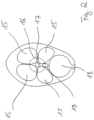
- FIG. 2 which shows a schematic representation of a cross section of a tuna
- the functionality of the device according to the invention for the non-contact detection of the red tissue structures 16 is to be explained by way of example.
- the red tissue structures 16 shown are red muscle meat.
- the present invention is not limited to the detection of the red muscle meat 16 in tuna, but is fundamentally also suitable for other products 12, for example fillets or meat components of other animal species.
- the Indian Figure 2 The highly schematic cross-section of a tuna shown shows the muscle strands 15 which enclose the red tissue structures 16 of red muscle meat which are heavily supplied with blood.
- the red tissue structures 16 in turn enclose the spine 17.
- a large blood vessel 19 is arranged between the spine 17 and the abdominal cavity 18, which is responsible, among other things, for the strong blood flow to the red muscle flesh.
- the muscle strands 15 and the red muscle flesh are translucent tissue.
- the muscle strands 15 and the red tissue structures 16 with the red muscle flesh have different opacities, ie a different light permeability. Due to the different opacities, the light line appears to be of different widths on the surface of the product 12.
- the detection device 14 is designed and set up to evaluate the images recorded by the optical sensor, in particular by evaluating the width of the light lines for detecting the red muscle meat.
- the light source 13 and the optical sensor means are preferably arranged at a distance from one another, ie the light source 13 and the optical sensor means are arranged at a distance from one another with respect to the conveying direction F, for example in order to determine the height contour of the product 12.
- the detection device 14 - as in the Fig. 1 shown - is arranged in such a way that the light components 32 reflected by the product 12 are recorded at a viewing angle ⁇ of less than 90 ° with respect to the conveying direction F.
- the viewing angle ⁇ here denotes the angle between the conveying direction F and the reflected light components 32.
- the light source 13 and the detection device 14 are arranged in such a way that both the illumination of the product 12 by means of the flat light field 31 and the recording of the light from the Product 12 reflected light components 32 are tilted.
- the light source 13 and the detection device 14 are further arranged such that the light field angle a is greater than the viewing angle ⁇ .
- the angular difference ⁇ between the light field angle a and the viewing angle ⁇ denotes the angle between the flat light field 31 falling on the product 12 and the reflected light components 32.
- the detection device 14 is arranged downstream of the light source 13 in the conveying direction F.
- the detection device 14 and the light source 13 are arranged such that the products 12 are illuminated at an angle opposite to the conveying direction F and the reflected light components 32 have at least one partial component which also points in the conveying direction F.
- the light source 13 is designed as a line laser. Line lasers with an output of 5 to 500 mW are preferably used.
- the light source 13 is a conventional light source with a correspondingly high luminous flux and adapted optics for generating the flat light field 31 described above and the light line running on the product 12.
- the light source 13 has a wavelength in the range between 650 and 900 nm and is thus optimally adapted to the absorption properties of highly perfused tissues, such as the red tissue structures 16.
- the detection device 14 is designed and configured to record a plurality of individual images of the product 12.
- the detection device 14 is configured such that a plurality of individual images are created of the product 12, which represent a plurality of segments of the continuously conveyed product 12.
- the detection device 14 comprises an evaluation means which is designed and set up to evaluate the recorded individual images.
- the evaluation means is also designed and set up to determine boundary lines between the areas of the red tissue structures 16, in particular the red muscle meat, and the remaining product areas 33, for example the muscle strands 15, on the basis of the individual images.
- the evaluation means for determining lines is preferably the same Light intensity in the individual images is designed and set up to determine the boundary lines.
- the boundary lines define the transition between the red tissue structures 16 and the remaining tissue parts, in particular the muscle strands 15.
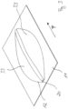
- a tuna fillet including part of the conveyor device 11 is shown schematically in a perspective view.
- the aforementioned area of red tissue structures 16 is as a strip 20 of red muscle meat Figure 3 refer to.
- the product 12, for example a tuna fish fillet, is aligned along the spine 17 in the conveying direction F and is transported by means of the - in the Figure 3 only schematically indicated - conveyor device 11 is continuously conveyed.
- the present invention also includes an arrangement for releasing the strip 20 of red tissue structures 16 from the products 12.
- the arrangement comprises the previously described device for the contactless detection of the red tissue structures 16 in the product 12 or in the products 12.
- a cutting device 21 not shown in the figures.
- the cutting device 21 is designed and set up for partially or completely releasing the strip 20 of the red fabric structures 16 from the products 12.
- the cutting device 21 is controlled by means of a control device - not shown in the drawing.
- the control device controls the cutting device 21 in such a way that the areas, in particular the strips 20, determined by means of the device according to the invention for non-contact detection of the red tissue structures 16, are completely or partially detached from the products 12.
- the cutting device is optionally set up in such a way that either the strip 20 is completely detached from or from the product 12 or only partial detachment takes place in that the strip 20 is detached in partial areas by cuts or incisions in the product 12, but after Cutting is still connected to the product 12 in order to be finally detached from the product 12, for example by means of subsequent manual processing.
- the cutting device 21 is designed to be movable relative to the product 12, so that the distance, in particular the vertical distance, between the product 12 and the cutting device 21 is designed to be variable.
- the cutting device 21 comprises at least one - in the Actuator not shown in the drawing.
- the cutting device 21 is designed to be controllable by means of the actuator, ie the position of the cutting device 21 is set up to be variable relative to the product 12 or relative to the conveyor device 11.
- the cutting device is controlled in its position by means of the control device in such a way that the red fabric structures or the strip 20 are partially or completely detached from the product 12.
- the cutting device 21 is designed to be variable in height, i.e. the distance between the respective cutting edge and the product 12. In this way, the depth of immersion of the cutting device 21 into the product 12 is designed to be variable for partially or completely detaching the red fabric structures 16 or the strip 20.
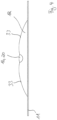
- the Figure 4 shows a schematic representation of the in the Figure 3 shown tuna fillets and the part of the conveyor device 11 in cross section.
- the conveying direction F points in the Figure 4 into the drawing plane.
- the area of the red tissue structures 16 of the red muscle meat can be seen in the form of the strip 20, to which the remaining product areas 33 adjoin on both sides.
- the present invention also includes a method for contactless detection of red tissue structures 16 in products 12 of slaughtered animal carcasses.
- a method for contactless detection of red tissue structures 16 in products 12 of slaughtered animal carcasses To avoid repetition, reference is made in full to the statements made above regarding the device 10 according to the invention and the arrangement according to the invention in connection with the method according to the invention. The statements in connection with the device 10 and the arrangement relate analogously to the method according to the invention. To clarify the sequence of the method according to the invention, selected aspects of the method are described in addition below.
- the method of the type mentioned at the beginning includes the following steps.
- the products 12 are continuously conveyed in the conveying direction F through an inspection area 30.
- the inspection area 30 is defined by the in the Figure 1 light source 13 shown and the detection device 14 are formed.
- the inspection area 30 includes the one in the Figure 1 Detection area of the detection device 14 limited by the dashed lines.
- the light source 13 By means of the light source 13, the products 12 are exposed to a flat light field 31, the light source 13 or the flat light field 31 emitted by it forming a transverse
- the light line running in the conveying direction F is formed.
- the light components 32 reflected by the product 12 are recorded by means of the optical sensor means of the detection device 14.
- Reflected light components 32 refer to both light components 32 that are directly reflected on the product surface, but in particular the light components that penetrate into deeper layers of the product and are scattered there.
- the products 12 are exposed to light by means of the light source 13, which is designed as an infrared light source. Furthermore, the plane of the flat light field is inclined relative to the conveyor 11 by a light field angle a of less than 90°.
Description
Die vorliegende Erfindung betrifft eine Vorrichtung zur berührungslosen Erkennung roter Gewebestrukturen in Produkten geschlachteter Tierkörper. Des Weiteren betrifft die vorliegende Erfindung ein Verfahren zum berührungslosen Erkennen roter Gewebestrukturen in Produkten geschlachteter Tierkörper sowie eine Anordnung zum Lösen eines Streifens roter Gewebestrukturen aus Produkten geschlachteter Tierkörper.The present invention relates to a device for the non-contact detection of red tissue structures in products from slaughtered animal carcasses. The present invention further relates to a method for non-contact detection of red tissue structures in products of slaughtered animal carcasses and an arrangement for releasing a strip of red tissue structures from products of slaughtered animal carcasses.
Solche Vorrichtungen, Verfahren und Anordnungen kommen in unterschiedlichen Bereichen der industriellen Verarbeitung von geschlachteten Tierkörpern, beispielsweise bei der Verarbeitung von Fisch-, Fleisch- oder Geflügelprodukten zum Einsatz, insbesondere bei der Verarbeitung von Fischfilets, beispielsweise bei der Verarbeitung von Thunfischen, z.B. von Skipjacks. Bei den roten Gewebestrukturen handelt es sich in der Regel um stark durchblutete Gewebetypen, die sich optisch von anderen Geweben unterscheiden. Beispielsweise umfassen die genannten roten Gewebestrukturen stark durchblutetes Muskelfleisch.Such devices, methods and arrangements are used in various areas of the industrial processing of slaughtered animal carcasses, for example in the processing of fish, meat or poultry products, in particular in the processing of fish fillets, for example in the processing of tuna, e.g. skipjacks. The red tissue structures are usually highly perfused tissue types that are visually different from other tissues. For example, the red tissue structures mentioned include highly perfused muscle meat.
Es ist bekannt, die zu untersuchenden Produkte, beispielsweise Fischfilets, mit Licht zu beaufschlagen und die reflektierte Teilstrahlung bzw. die in dem Produkt, insbesondere in einem transluzenten Produkt gestreute Lichtstrahlung, mittels einer Detektionseinrichtung zu detektieren, um Rückschlüsse auf die Produktbeschaffenheit zu ziehen. Eine Vorrichtung sowie ein Verfahren zum kontaktlosen Erkennen von Charakteristika transluzenter Produkte geht beispielsweise aus dem Dokument
Die
Die
Mit den bekannten Vorrichtungen und Verfahren ist es zwar möglich, Fremdkörper und/oder Fremdgewebetypen zu detektieren, jedoch findet keine Differenzierung zwischen verschiedenen Gewebetypen statt, so dass sich die bekannten Vorrichtungen und Verfahren nicht zur Erkennung von bestimmten Gewebetypen, insbesondere nicht zur Erkennung stark durchbluteter Gewebe eignen.Although it is possible to detect foreign bodies and/or foreign tissue types using the known devices and methods, no differentiation is made between different tissue types, so that the known devices and methods are not suitable for detecting certain tissue types, in particular not for detecting tissue with a high blood supply.
Es ist daher Aufgabe der vorliegenden Erfindung, eine Vorrichtung vorzuschlagen, die eine zuverlässige Erkennung und Differenzierung unterschiedlicher durchbluteter Gewebetypen in den Produkten gewährleistet. Des Weiteren besteht die Aufgabe darin, ein entsprechendes Verfahren vorzuschlagen. Ferner besteht die Aufgabe darin, eine Anordnung vorzuschlagen, die das automatische Herauslösen bestimmter Gewebetypen aus den Produkten zuverlässig gewährleistet.It is therefore the object of the present invention to propose a device which ensures reliable detection and differentiation of different types of tissue in the products that are perfused with blood. Furthermore, the task is to propose an appropriate procedure. Furthermore, the task is to propose an arrangement that reliably ensures the automatic removal of certain types of tissue from the products.
Die Aufgabe wird durch eine Vorrichtung mit den Merkmalen des Anspruchs 1 gelöst. Das verwendete infrarote Licht wird in den Bereichen der roten Gewebestrukturen stärker in dem Produkt absorbiert als dies in den übrigen Gewebebestandteilen des Produkts der Fall ist. Der Unterschied fällt besonders groß zwischen den roten Gewebestrukturen und dem übrigen Gewebe aus, so dass die Bereiche mit den roten Gewebestrukturen exakt und mit hoher Zuverlässigkeit erkannt werden. Die vorliegende Erfindung eignet sich daher grundsätzlich zur Erkennung von roten Gewebestrukturen, beispielsweise von stark durchbluteten Geweben, insbesondere von rotem Muskelfleisch. Auch ist es möglich, verletzte Gewebebereiche, beispielsweise hämatöse Bereiche, von anderen Gewebestrukturen bzw. Produktbereichen zu differenzieren.The object is achieved by a device having the features of
Nach der Erfindung sind die Lichtquelle und das optische Sensormittel in Förderrichtung voneinander beabstandet angeordnet. Aufgrund der daraus resultierenden Anordnung der Lichtquelle und des optischen Sensormittels bezüglich des Produktes ist es möglich, zugleich ein Höhenprofil bzw. eine Höhenkontur des Produktes zu erfassen.According to the invention, the light source and the optical sensor means are arranged at a distance from one another in the conveying direction. Due to the resulting arrangement of the light source and the optical sensor means with respect to the product, it is possible to simultaneously record a height profile or a height contour of the product.
Gemäß der Erfindung ist die Detektionseinrichtung derart angeordnet, dass die von dem Produkt reflektierten Lichtanteile unter einem Betrachtungswinkel kleiner 90° gegenüber der Förderrichtung aufgenommen werden. Dies bietet den Vorteil, dass die quer zur Förderrichtung auf dem Produkt verlaufende Lichtlinie nicht aufgrund von Oberflächenunebenheiten des Produktes teilweise verschattet wird. So wird die Lichtlinie von der Detektionseinrichtung lückenlos bzw. unterbrechungsfrei und weitestgehend unabhängig von Unebenheiten der Produktoberfläche erfasst.According to the invention, the detection device is arranged in such a way that the light components reflected by the product are recorded at a viewing angle of less than 90° relative to the conveying direction. This offers the advantage that the line of light running across the product perpendicular to the conveying direction is not partially shaded due to surface irregularities of the product. The line of light is thus recorded by the detection device without gaps or interruptions and largely independently of any unevenness in the product surface.
Gemäß der Erfindung sind außerdem die Lichtquelle und die Detektionseinrichtung derart angeordnet, dass der Lichtfeldwinkel größer als der Betrachtungswinkel ist. Dies bietet den Vorteil, dass die reflektierten Lichtanteile, die von der Detektionseinrichtung unter dem Betrachtungswinkel aufgenommen werden nicht durch Unebenheiten auf der Oberfläche des Produktes verschattet oder verdeckt werden können, so dass die reflektierten Lichtanteile in jedem Fall ungehindert zu der Detektionseinrichtung gelangen.According to the invention, the light source and the detection device are also arranged such that the light field angle is larger than the viewing angle. This offers the advantage that the reflected light components, which recorded by the detection device at the viewing angle cannot be shaded or obscured by unevenness on the surface of the product, so that the reflected light components always reach the detection device unhindered.
Dadurch, dass die Detektionseinrichtung der Lichtquelle in Förderrichtung nachgeordnet angeordnet ist, wird ebenfalls gewährleistet, dass die Lichtlinie auf dem Produkt durchgängig und unabhängig von Oberflächenunebenheiten aus dem flächigen Lichtfeld gebildet wird.The fact that the detection device is arranged downstream of the light source in the conveying direction also ensures that the light line on the product is formed from the flat light field continuously and independently of surface irregularities.
Gemäß einer weiteren bevorzugten Ausführungsform ist die Lichtquelle als Linienlaser ausgebildet. Der Linienlaser bietet den Vorteil, dass das Produkt einerseits mit Licht hoher Intensität beaufschlagt wird, so dass das Licht entsprechend weit in das Produkt eindringt. So ist eine Erkennung bzw. Differenzierung von tieferliegenden Gewebestrukturen, beispielsweise Muskelfleischbereichen, möglich. Anderseits ist das Licht des Linienlasers stark fokussiert, so dass die Lichtlinie auf dem Produkt möglichst schmal ausgebildet ist. Mit anderen Worten wird mit dem Linienlaser eine starke Fokussierung des Lichtstroms in einem möglichst schmalen flächigen Lichtfeld erzielt, so dass die Lichtlinie auf dem Produkt sowohl mit hoher Intensität als auch stark fokussiert auftrifft. Dies bietet den Vorteil einer hohen Ortsauflösung bei der Erkennung der roten Gewebestrukturen sowie einer sehr guten Empfindlichkeit bei der Differenzierung zwischen den roten Gewebestrukturen und anderen Gewebetypen und/oder weiteren Bestandteilen des Produktes.According to a further preferred embodiment, the light source is designed as a line laser. The line laser offers the advantage that the product is exposed to high-intensity light so that the light penetrates the product accordingly. This makes it possible to detect or differentiate deeper tissue structures, for example muscle areas. On the other hand, the light from the line laser is highly focused so that the line of light on the product is as narrow as possible. In other words, the line laser achieves a strong focus of the light flux in a light field that is as narrow as possible so that the line of light hits the product with both high intensity and a high focus. This offers the advantage of high spatial resolution when detecting the red tissue structures and very good sensitivity when differentiating between the red tissue structures and other tissue types and/or other components of the product.
Erfindungsgemäß weist die Lichtquelle eine Wellenlänge zwischen 650 nm und 900 nm auf. Licht mit einer Wellenlänge zwischen 650 nm und 900 nm wird aufgrund der besonders ausgeprägten Absorptionseigenschaften der roten Gewebestrukturen stark absorbiert, so dass die in dem Produkt gestreuten bzw. reflektierten Lichtanteile entsprechend stark gedämpft werden. Aus diesem Grund weist die von der Detektionseinrichtung ausgewertete Linienbreite auf dem Produkt in Bereichen roter Gewebestrukturen eine deutlich geringere Breite auf, als in anderen Bereichen, da die starke Dämpfung des Lichtstromes in den roten Gewebestrukturen den Lichtstreubereich entsprechend stark reduziert. In den übrigen Bereichen, in denen die Absorption des einfallenden Lichtstromes deutlich geringer ist, ist der Streubereich deutlich größer, so dass die Linienbreite der Lichtlinie in diesen Bereichen entsprechend breiter ist. Auf Basis der verschiedenen Lichtlinienbreiten ist so eine zuverlässige und exakte Erkennung der roten Gewebestrukturen möglich.According to the invention, the light source has a wavelength between 650 nm and 900 nm. Light with a wavelength between 650 nm and 900 nm is strongly absorbed due to the particularly pronounced absorption properties of the red tissue structures, so that the light components scattered or reflected in the product are correspondingly strongly attenuated. For this reason, the line width on the product evaluated by the detection device has a significantly smaller width in areas of red fabric structures than in other areas, since the strong attenuation of the luminous flux in the red fabric structures correspondingly reduces the light scattering area. In the remaining areas where the absorption of the incident luminous flux is significantly lower, the scattering area is significantly larger, so that the line width of the light line is correspondingly wider in these areas. Based on the different light line widths, reliable and precise detection of the red tissue structures is possible.
Gemäß einer weiteren bevorzugten Ausbildung der Erfindung ist die Detektionseinrichtung zum Aufnehmen mehrerer Einzelbilder ausgebildet und eingerichtet. Mit anderen Worten ist die Detektionseinrichtung zum getakteten Aufnehmen eine Vielzahl von Bildern von dem Produkt bzw. von der auf dem Produkt vorhandenen Lichtlinie ausgebildet und eingerichtet. Auf diese Weise wird der Verlauf der Kontur des Produktes erfasst, so dass die Position der roten Gewebestrukturen über die gesamte Produktlänge ermittelt wird.According to a further preferred embodiment of the invention, the detection device is designed and configured to record a plurality of individual images. In other words, the detection device is designed and configured to record a plurality of images of the product or of the light line present on the product in a timed manner. In this way, the course of the contour of the product is recorded, so that the position of the red fabric structures is determined over the entire length of the product.
Eine weitere zweckmäßige Ausbildung der Erfindung ist dadurch gekennzeichnet, dass die Detektionseinrichtung ein Auswertemittel umfasst, das zum Bestimmen von Grenzlinien zwischen Bereichen der roten Gewebestrukturen und den übrigen Produktbereichen des Produktes auf Basis der Einzelbilder ausgebildet und eingerichtet ist. Dies bietet den Vorteil, dass die Detektionseinrichtung zur Ermittlung der Grenzen zwischen den roten Gewebestrukturen und den übrigen Bereichen ausgebildet und eingerichtet ist. Die Grenzlinien können beispielsweise für eine nachfolgende Bearbeitung des Produktes als Schnittlinien dienen.A further expedient embodiment of the invention is characterized in that the detection device comprises an evaluation means which is designed and set up to determine boundary lines between areas of the red fabric structures and the other product areas of the product on the basis of the individual images. This offers the advantage that the detection device is designed and set up to determine the boundaries between the red fabric structures and the other areas. The boundary lines can serve as cutting lines for subsequent processing of the product, for example.
Gemäß einer weiteren vorteilhaften Ausbildung der Erfindung ist das Auswertemittel zum Ermitteln von Linien gleicher Lichtintensität in den Einzelbildern zur Bestimmung der Grenzlinien ausgebildet und eingerichtet. Die Lichtlinien, bzw. die Linienverläufe gleicher Lichtintensität, die als Isoluxe bezeichnet werden, bilden so die Ausgangsbasis zur Bestimmung der Grenzlinien. Auf diese Weise ist es ferner möglich, durch Vorgabe eines Lichtintensitätsschwellwertes den von den Grenzlinien begrenzten Bereich um die roten Gewebestrukturen variabel einzustellen. Mittels des Lichtintensitätsschwellenwertes wird so vorgegeben, an welcher Position bzw. in welchem Abstand von den roten Gewebestrukturen die Grenzlinien detektiert bzw. ermittelt werden. Mit anderen Worten kann so ein Toleranzbereich eingestellt werden, um zu gewährleisten, dass keine Bestandteile der roten Gewebestrukturen außerhalb des von den Grenzlinien bezeichneten Bereichs in dem Produkt vorhanden sind.According to a further advantageous embodiment of the invention, the evaluation means is designed and set up to determine lines of the same light intensity in the individual images to determine the boundary lines. The light lines, or the line progressions of the same light intensity, which are referred to as isoluxes, form the starting point for determining the boundary lines. In this way, it is also possible to variably adjust the area delimited by the boundary lines around the red tissue structures by specifying a light intensity threshold value. The light intensity threshold value is used to specify at what position or at what distance from the red tissue structures the boundary lines are detected or determined. In other words, a tolerance range can be set to ensure that no components of the red tissue structures are present in the product outside the area designated by the boundary lines.
Des Weiteren wird die Aufgabe durch eine Anordnung mit den Merkmalen des Anspruchs 7 gelöst. Mittels der erfindungsgemäßen Anordnung ist es erstmalig möglich, die roten Gewebestrukturen vollständig automatisiert aus den Produkten zuverlässig und exakt herauszulösen.Furthermore, the task is solved by an arrangement with the features of claim 7. By means of the arrangement according to the invention, it is possible for the first time to reliably and precisely remove the red tissue structures from the products in a completely automated manner.
Gemäß einer weiteren bevorzugten Ausführungsform ist die Schneideinrichtung relativ zu dem Produkt bewegbar ausgebildet. Dies bietet den Vorteil, dass die Schneideinrichtung während des Vorbeilaufens eines der kontinuierlich geförderten Produkte an das Produkt herangeführt, bzw. in das Produkteingeführt werden kann, um so die Schnittführung exakt an die Bereiche der ermittelten roten Gewebestrukturen bzw. an die Grenzlinien anzupassen.According to a further preferred embodiment, the cutting device designed to be movable relative to the product. This offers the advantage that the cutting device can be brought up to the product or introduced into the product while one of the continuously conveyed products is passing by, in order to adapt the cutting route exactly to the areas of the red tissue structures determined or to the boundary lines.
Eine weitere zweckmäßige Ausgestaltung der Erfindung ist dadurch gekennzeichnet, dass die Schneideinrichtung mindestens ein Stellglied umfasst, mittels dessen die Schneideinrichtung zum teilweisen oder vollständigen Lösen der roten Gewebestrukturen aus dem Produkt steuerbar eingerichtet ist. Mittels des Stellgliedes ist die Position der Schneiderichtung mittels der Steuerungseinrichtung einstellbar ausgebildet, so dass das Lösen der roten Gewebestrukturen vollständig automatisch und im Idealfall ohne eine manuelle Nachbearbeitung erfolgt.A further expedient embodiment of the invention is characterized in that the cutting device comprises at least one actuator, by means of which the cutting device is designed to be controllable for partially or completely detaching the red fabric structures from the product. By means of the actuator, the position of the cutting direction is adjustable by means of the control device, so that the detachment of the red fabric structures takes place completely automatically and ideally without manual post-processing.
Gemäß einer weiteren bevorzugten Ausbildung der Erfindung ist die Schneideinrichtung höhenverstellbar ausgebildet und eingerichtet, so dass zum teilweisen oder vollständigen Lösen der roten Gewebestrukturen aus dem Produkt die Eintauchtiefe der Schneideinrichtung in das Produkt veränderbar ausgebildet ist. Mittels der veränderbar eingerichteten Eintauchtiefe, also einem Maß, wie weit beispielsweise eine Schneidkante der Schneideinrichtung in das Produkt eindringt, wird das Höhenprofil des Produktes beim Lösen der roten Gewebestrukturen berücksichtigt, so dass eine vollständige Trennung bzw. ein teilweises Lösen der roten Gewebestrukturen von dem restlichen Produkt mit hoher Präzision erfolgt.According to a further preferred embodiment of the invention, the cutting device is designed and set up to be height-adjustable, so that the immersion depth of the cutting device into the product is designed to be changeable in order to partially or completely release the red tissue structures from the product. By means of the changeable immersion depth, i.e. a measure of how far, for example, a cutting edge of the cutting device penetrates into the product, the height profile of the product is taken into account when releasing the red fabric structures, so that a complete separation or partial release of the red fabric structures from the rest Product is made with high precision.
Die vorliegende Aufgabe wird auch durch ein Verfahren mit den Merkmalen des Anspruchs 11 gelöst. Das erfindungsgemäße Verfahren bietet -wie schon zuvor im Zusammenhang mit der erfindungsgemäßen Vorrichtung im Detail erläutert -den Vorteil einer zuverlässigen und exakten Erkennung der roten Gewebestrukturen in den Produkten.The present task is also solved by a method with the features of
Das Aufnehmen der von dem Produkt reflektierten Lichtanteile erfolgt unter einem Betrachtungswinkel kleiner 90° gegenüber der Förderrichtung. Dies bietet den Vorteil, dass die quer zur Förderrichtung auf dem Produkt verlaufende Lichtlinie nicht aufgrund von Oberflächenunebenheiten des Produkts teilweise verschattet wird. So wird die Lichtlinie von der Detektionseinrichtung lückenlos bzw. unterbrechungsfrei und weitestgehend unabhängig von Unebenheiten der Produktoberfläche erfasst.The light reflected from the product is recorded at a viewing angle of less than 90° to the conveying direction. This offers the advantage that the line of light running across the product perpendicular to the conveying direction is not partially shaded due to surface irregularities on the product. The light line is thus recorded by the detection device without gaps or interruptions and largely independent of any unevenness on the product surface.
Der Lichtfeldwinkel ist größer als der Betrachtungswinkel. Dies bietet den Vorteil, dass die reflektierten Lichtanteile, die von der Detektionseinrichtung unter dem Betrachtungswinkel aufgenommen werden nicht durch Unebenheiten auf der Oberfläche des Produktes verschattet oder verdeckt werden können, so dass die reflektierten Lichtanteile in jedem Fall ungehindert zu der Detektionseinrichtung gelangen.The light field angle is larger than the viewing angle. This offers the advantage that the reflected light components that are recorded by the detection device at the viewing angle cannot be shaded or obscured by unevenness on the surface of the product, so that the reflected light components always reach the detection device unhindered.
Eine weitere zweckmäßige Ausbildung der Erfindung ist dadurch gekennzeichnet, dass mehrere Einzelbilder mittels der Detektionseinrichtung von jedem der Produkte aufgenommen werden. Mittels der Aufnahme mehrerer Einzelbilder von dem Produkt bzw. von der Lichtlinie auf dem Produkt wird der Verlauf der Kontur des Produktes erfasst, so dass die Position der roten Gewebestrukturen über die gesamte Produktlänge ermittelt wird.A further expedient embodiment of the invention is characterized in that several individual images of each of the products are recorded by means of the detection device. By taking several individual images of the product or of the light line on the product, the course of the contour of the product is recorded so that the position of the red tissue structures is determined over the entire length of the product.
Eine weitere zweckmäßige Ausgestaltung der Erfindung ist dadurch gekennzeichnet, dass auf Basis der Einzelbilder mittels eines Auswertemittel Grenzlinien zwischen Bereichen der roten Gewebestrukturen und den übrigen Produktbereichen des Produktes bestimmt werden.A further expedient embodiment of the invention is characterized in that, on the basis of the individual images, boundary lines between areas of the red tissue structures and the remaining product areas of the product are determined by means of an evaluation means.
Gemäß einer weiteren vorteilhaften Ausgestaltung der Erfindung werden Linien gleicher Lichtintensität in den Einzelbildern zur Bestimmung der Grenzlinien mittels der Auswertemittel bestimmt. Die jeweiligen Vorteile wurden bereits zuvor im Zusammenhang mit der erfindungsgemäßen Vorrichtung beschrieben, so dass zur Vermeidung von Wiederholungen auf die entsprechenden Passagen der Beschreibung verwiesen wird.According to a further advantageous embodiment of the invention, lines of equal light intensity are determined in the individual images for determining the boundary lines by means of the evaluation means. The respective advantages have already been described previously in connection with the device according to the invention, so that reference is made to the corresponding passages of the description in order to avoid repetition.
Weitere bevorzugte und/oder zweckmäßige Merkmale und Ausgestaltungen der Erfindung ergeben sich aus den Unteransprüchen und der Beschreibung. Besonders bevorzugte Ausführungsformen werden anhand der beigefügten Zeichnung näher erläutert. In der Zeichnung zeigt:
- Fig. 1
- eine schematische Darstellung einer ersten Ausführungsform der erfindungsgemäßen Vorrichtung in Seitenansicht,
- Fig. 2
- eine schematische Darstellung eines Querschnitts eines Thunfisches,
- Fig. 3
- eine schematische Darstellung eines Thunfischfilets einschließlich eines Teils einer Fördereinrichtung in perspektivischer Darstellung und
- Fig. 4
- eine schematische Darstellung des in
Fig. 3 dargestellten Thunfischfilets sowie des Teils der Förderreinrichtung im Querschnitt.
- Fig. 1
- a schematic representation of a first embodiment of the device according to the invention in side view,
- Fig. 2
- a schematic representation of a cross section of a tuna,
- Fig. 3
- including a schematic representation of a tuna fillet part of a conveyor device in a perspective view and
- Fig. 4
- a schematic representation of the in
Fig. 3 The tuna fillets shown and the part of the conveyor device in cross section.
In der
Die Vorrichtung 10 umfasst ferner eine Lichtquelle 13. Die Lichtquelle 13 ist derart eingerichtet und ausgebildet, dass diese ein flächiges Lichtfeld 31 aussendet, wobei das flächige Lichtfeld 31 eine quer zu der Förderrichtung F verlaufende Lichtlinie bildet. Anders ausgedrückt ist die Lichtquelle 13 zur Bildung einer Lichtlinie auf dem Produkt 12, die quer zu der Förderrichtung F verläuft, ausgebildet und eingerichtet.The device 10 further comprises a
Die Vorrichtung 10 umfasst weiter eine Detektionseinrichtung 14 mit einem optischen Sensormittel. Alternativ umfasst die Detektionseinrichtung 14 mehrere Sensormittel. Das optische Sensormittel ist zur Aufnahme der von dem Produkt 12 reflektierten Lichtanteile (32) ausgebildet und eingerichtet. Das optische Sensormittel ist beispielsweise als CCD-Kamera oder als CCD-Zeilenkamera ausgebildet. Vorzugweise ist die Lichtquelle 13 eine Infrarotlichtquelle. Besonders bevorzugt ist die Lichtquelle 13 zur Aussendung von Licht im infraroten Wellenlängenbereich ausgebildet. Alternativ umfasst die Lichtquelle 13 einen Wellenlängenbereich ausgehend vom Infrarotbereich bis hin zum sichtbaren Rot.The device 10 further comprises a
Die Lichtquelle 13 ist derart angeordnet, dass die Ebene des flächigen Lichtfeldes 31 gegenüber der Förderrichtung F um einen Lichtfeldwinkel α kleiner 90° geneigt ist. Mit anderen Worten ist die Ebene vorzugsweise nicht orthogonal zu der Förderrichtung F ausgerichtet, so dass die Ebene des flächigen Lichtfeldes 31 nicht senkrecht auf die Oberfläche der Produkte 12 trifft, sondern um einen entsprechenden Winkelbetrag geneigt ist. Die Schrägstellung des flächigen Lichtfeldes 31 führt zu einer Verformung der Lichtlinien auf dem Produkt 12 in Abhängigkeit der Geometrie des Produktes 12, so dass anhand des Verlaufs der Lichtlinien auf die Form und Geometrie des Produktes 12 rückgeschlossen werden kann.The
Vorzugsweise ist das optische Sensormittel der Detektionseinrichtung 14 zur Aufnahme von Bildern der entsprechend der Geometrie des Produktes 12 verlaufenden Lichtlinien ausgebildet und eingerichtet und auf den jeweiligen Wellenlängen des von der Lichtquelle 13 ausgesandten Lichts angepasst.Preferably, the optical sensor means of the
Alternativ kann die Detektionseinrichtung 14 auch weitere optische Sensoren umfassen, die zur Aufnahme von Bildern bzw. von Bilddaten in einem anderen, beispielsweise im sichtbaren, Wellenlängenbereich ausgebildet und eingerichtet sind. Die Detektionseinrichtung 14 ist in diesem Fall zur Verarbeitung der Signale mehrerer der optischen Sensoren eingerichtet. Beispielsweise weist die Detektionseinrichtung 14 Verarbeitungsmittel zur Überlagerung der aufgenommenen Bilder von mehreren der optischen Sensoren auf.Alternatively, the
Des Weiteren ist zusätzlich zu der Lichtquelle 13 eine weitere - in der Zeichnung nicht gezeigte - Lichtquelle zur Beleuchtung des Produktes 12 mit Licht sichtbarer Wellenlänge angeordnet. Während die Detektionseinrichtung 14 neben dem optischen Sensormittel zur Aufnahme von Bildern des Produktes 12 und der auf diesem verlaufenden Lichtlinien im Infrarotbereich umfasst, ist zusätzlich ein weiteres - in der Zeichnung ebenfalls nicht gezeigtes - optisches Sensormittel zur Aufnahme von Bildern des Produktes 12 im sichtbaren Lichtwellenlängenbereich angeordnet. Besonders bevorzugt sind das optische Sensormittel sowie das weitere optische Sensormittel als ein integrales Sensormittel, d.h. zusammen als ein Sensormittel, ausgebildet. Beispielsweise ist dieses eine Sensormittel als Kamera ausgebildet, die sowohl für den infraroten als auch für den sichtbaren Lichtwellenlängenbereich empfindlich ist. Mit anderen Worten umfasst die Detektionseinrichtung 14 vorzugsweise nur ein Sensormittel, das sowohl zur Aufnahme von Bildern im infraroten als auch im sichtbaren Lichtwellenlängenbereich ausgebildet und eingerichtet ist. Wie zuvor beschrieben ist die Detektionseinrichtung 14 vorzugsweise dazu angepasst, mittels des Verarbeitungsmittels durch Kombination der aufgenommenen Bilder im sichtbaren sowie im infraroten Lichtwellenlängenbereich zusätzliche Informationen über die Beschaffenheit, insbesondere der Geometrie, der Produkte 12 zu ermitteln. Beispielsweise ist es auf diese Weise möglich, geometrische Daten des Produktes 12, wie die Produktbreite oder die Produktkontur zu ermitteln.Furthermore, in addition to the
Anhand der
Der in der
Die Detektionseinrichtung 14 - wie in der
Die Lichtquelle 13 und die Detektionseinrichtung 14 sind ferner derart angeordnet, dass der Lichtfeldwinkel a größer als der Betrachtungswinkel β ist.The
Die Winkeldifferenz δ zwischen dem Lichtfeldwinkel a und dem Betrachtungswinkel β, bezeichnet den Winkel zwischen dem auf das Produkt 12 fallenden flächigen Lichtfeld 31 und den reflektierten Lichtanteilen 32.The angular difference δ between the light field angle a and the viewing angle β denotes the angle between the flat
Die Detektionseinrichtung 14 ist der Lichtquelle 13 in Förderrichtung F nachgeordnet angeordnet. Mit anderen Worten sind die Detektionseinrichtung 14 und die Lichtquelle 13 derart angeordnet, dass die Produkte 12 entgegen der Förderrichtung F schräg geneigt beleuchtet werden und die reflektierten Lichtanteile 32 zumindest eine Teilkomponente aufweisen, die ebenfalls in die Förderrichtung F zeigt.The
Weiter bevorzugt ist die Lichtquelle 13 als Linienlaser ausgebildet. Vorzugsweise kommen Linienlaser mit einer Leistung von 5 bis zu 500 mW zum Einsatz. Alternativ ist die Lichtquelle 13 eine konventionelle Lichtquelle mit entsprechend hohem Lichtstrom und einer angepassten Optik zur Erzeugung des zuvor beschriebenen flächigen Lichtfeldes 31 sowie der auf dem Produkt 12 verlaufenden Lichtlinie.More preferably, the
Erfindungsgemäß weist die Lichtquelle 13 eine Wellenlänge im Bereich zwischen 650 und 900 nm auf, und ist damit optimal auf die Absorbtionseigenschaften von stark durchbluteten Geweben, wie den roten Gewebestrukturen 16, angepasst.According to the invention, the
Vorteilhafter Weise ist die Detektionseinrichtung 14 zum Aufnehmen mehrerer Einzelbilder von dem Produkt 12 ausgebildet und eingerichtet. Anders ausgedrückt, ist die Detektionseinrichtung 14 derart eingerichtet, dass von dem Produkt 12 mehrere Einzelbilder erstellt werden, die eine Vielzahl von Segmenten des kontinuierlich geförderten Produkts 12 darstellen.Advantageously, the
Weiter bevorzugt umfasst die Detektionseinrichtung 14 ein Auswertemittel, das zur Auswertung er aufgenommenen Einzelbilder ausgebildet und eingerichtet ist. Hierzu ist das Auswertemittel ferner zum Bestimmen von Grenzlinien zwischen den Bereichen der roten Gewebestrukturen 16, insbesondere des roten Muskelfleisches und den übrigen Produktbereichen 33, beispielsweise den Muskelsträngen 15, auf Basis der Einzelbilder ausgebildet und eingerichtet.Further preferably, the
Vorzugweise ist das Auswertemittel zum Ermitteln von Linien gleicher Lichtintensität in den Einzelbildern zur Bestimmung der Grenzlinien ausgebildet und eingerichtet. Die Grenzlinien definieren den Übergang zwischen den roten Gewebestrukturen 16 und den übrigen Gewebeteilen, insbesondere der Muskelstränge 15.The evaluation means for determining lines is preferably the same Light intensity in the individual images is designed and set up to determine the boundary lines. The boundary lines define the transition between the
In der
Vorteilhafter Weise umfasst die vorliegende Erfindung auch eine Anordnung zum Lösen des Streifens 20 roter Gewebestrukturen 16 aus den Produkten 12. Die Anordnung umfasst die zuvor beschriebene Vorrichtung zur berührungslosen Erkennung der roten Gewebestrukturen 16 in dem Produkt 12 bzw. in den Produkten 12. Ferner umfasst die Anordnung eine in den Figuren nicht gezeigte Schneideinrichtung 21. Die Schneideinrichtung 21 ist zum teilweisen oder vollständigen Lösen des Streifens 20 der roten Gewebestrukturen 16 aus den Produkten 12 ausgebildet und eingerichtet. Die Schneideinrichtung 21 wird mittels einer - in der Zeichnung nicht gezeigten - Steuerungseinrichtung gesteuert. Die Steuerungseinrichtung steuert die Schneideinrichtung 21 derart, dass die mittels der erfindungsgemäßen Vorrichtung zur berührungslosen Erkennung der roten Gewebestrukturen 16 ermittelten Bereiche, insbesondere der Streifen 20, vollständig oder teilweise von den Produkten 12 gelöst wird. Die Schneideinrichtung ist wahlweise derart eingerichtet, dass entweder der Streifen 20 vollständig aus bzw. von dem Produkt 12 gelöst wird oder nur ein teilweises Lösen erfolgt, indem der Streifen 20 durch Schnitte bzw. Einschnitte in das Produkt 12 in Teilbereichen gelöst wird, jedoch nach dem Schneiden noch mit dem Produkt 12 verbunden ist, um beispielsweise mittels einer nachfolgenden manuellen Bearbeitung endgültig vom Produkt 12 gelöst zu werden.Advantageously, the present invention also includes an arrangement for releasing the
Vorzugsweise ist die Schneideinrichtung 21 relativ zu dem Produkt 12 bewegbar ausgebildet, so dass der Abstand, insbesondere der vertikale Abstand, zwischen dem Produkt 12 und der Schneideinrichtung 21 veränderbar ausgebildet ist. Besonders bevorzugt umfasst die Schneideinrichtung 21 mindestens ein - in der Zeichnung nicht gezeigtes - Stellglied. Mittels des Stellgliedes ist die Schneideinrichtung 21 steuerbar ausgebildet, d.h. die Position der Schneideinrichtung 21 ist relativ zu dem Produkt 12 bzw. relativ zu der Fördereinrichtung 11 veränderbar eingerichtet. Mittels der Steuerungseinrichtung, wird die Schneideinrichtung in seiner Position derart gesteuert, dass die roten Gewebestrukturen bzw. der Streifen 20 teilweise oder vollständig aus dem Produkt 12 gelöst wird.Preferably, the cutting device 21 is designed to be movable relative to the
Vorteilhafter Weise ist die Schneideinrichtung 21 in der Höhe, d.h. der Abstand zwischen der jeweiligen Schneidkante und dem Produkt 12, veränderbar eingerichtet. Auf diese Weise ist die Eintauchtiefe der Schneideinrichtung 21 in das Produkt 12 zum teilweisen oder vollständigen Lösen der roten Gewebestrukturen 16 bzw. des Streifens 20 veränderbar ausgebildet.Advantageously, the cutting device 21 is designed to be variable in height, i.e. the distance between the respective cutting edge and the
Die
Die vorliegende Erfindung umfasst auch ein Verfahren zum berührungslosen Erkennen von roten Gewebestrukturen 16 in Produkten 12 geschlachteter Tierkörper. Zur Vermeidung von Wiederholungen wird im Zusammenhang mit dem erfindungsgemäßen Verfahren vollumfänglich auf die zuvor gemachten Ausführungen bezüglich der erfindungsgemäßen Vorrichtung 10 sowie der erfindungsgemäßen Anordnung verwiesen. Die Ausführungen im Zusammenhang mit der Vorrichtung 10 und der Anordnung betreffen in analoger Weise das erfindungsgemäße Verfahren. Zur Verdeutlichung des Ablaufs des erfindungsgemäßen Verfahrens werden im Folgenden ausgewählten Aspekten des Verfahrens ergänzend beschrieben.The present invention also includes a method for contactless detection of
Das Verfahren der eingangs genannten Art umfasst die folgenden Schritte. Die Produkte 12 werden kontinuierlich in die Förderrichtung F durch einen Inspektionsbereich 30 gefördert. Der Inspektionsbereich 30 wird durch die in der
Claims (14)
- Apparatus (10) for non-contact identifying of red tissue structures (16) in products (12) of slaughtered animal bodies, comprising a conveying device (11) for continuous conveyance of the products (12) in a conveying direction (F), a light source (13) configured to generate a flat light field (31) which is designed and adapted to form a light line running transversely to the conveying direction (F) of the product (12) from the flat light field (31), a detecting device (14) for identifying the red tissue structures (16) which comprises at least one optical sensor means for recording the portions of light (32) reflected by the product (12), wherein the light source (13) is configured as an infrared light source, whereinthe light source (13) and the optical sensor means are arranged spaced apart in the conveying direction (F), whereinthe light source (13) is arranged such that the plane of the flat light field (31) is tilted relative to the conveying direction (F) by a light field angle (α) of less than 90°, andthe detecting device (14) is arranged such that the light portions (32) reflected by the product (12) are recorded at a viewing angle (β) of less than 90° relative to the conveying direction (F), andthe light source (13) and detecting device (14) are arranged such that the light field angle (α) is greater than the viewing angle (β), and whereinthe light source (13) has a wavelength between 650 nm and 900 nm andthe detecting device (14) is designed to evaluate the line width of the light line on the product (12).
- Apparatus according to claim 1, characterised in that the detecting device (14) is arranged downstream of the light source (13) in the conveying direction (F).
- Apparatus according to claim 1 or 2, characterised in that the light source (13) is designed as a linear laser.
- Apparatus according to any one of claims 1 to 3, characterised in that the detecting device (14) is designed and adapted to record a plurality of individual images.
- Apparatus according to claim 4, characterised in that the detecting device (14) comprises an analysis means which is designed and adapted to determine border lines between areas of the red tissue structures (16) and the other product areas (33) of the product (12) on the basis of the individual images.
- Apparatus according to claim 5, characterised in that the analysis means is designed and adapted to detect lines of the same light intensity in the individual images in order to determine the border lines.
- Arrangement for removing a strip (20) of red tissue structures (16) from products (12) of slaughtered animal bodies, comprising an apparatus (10) for non-contact identifying of red tissue structures (16) in the products (12), a cutting device (21) for partial or complete removal of the red tissue structures (16) from the products (12), a control device adapted and designed to control the cutting device (21) along the regions determined by means of the apparatus (10) for non-contact identifying of red tissue structures (16), wherein the apparatus (10) for non-contact identifying of red tissue structures (16) in the products (12) is designed according to any one of claims 1 to 6.
- Arrangement according to claim 7, characterised in that the cutting device (21) is designed moveably relative to the product (12).
- Arrangement according to claim 8, characterised in that the cutting device (21) comprises at least one actuator, by means of which the cutting device (21) is adapted controllably for partial or complete removal of the red tissue structures (16) from the product (12).
- Arrangement according to any one of claims 7 to 9, characterised in that the cutting device (21) is designed and adapted height-adjustably so that the immersion depth of the cutting device (21) in the product (12) is designed variably for partial or complete removal of the red tissue structures (16) from the product (12).
- Method for non-contact identifying of red tissue structures (16) in products (12) of slaughtered animal bodies, comprising the steps:- continuous transport of the products (12) through an inspection area (30) in a conveying direction (F),- illumination of the products (12) by means of a flat light field (31) of a light source (13) to form a light line running transversely to the conveying direction (F) of the product (12),- recording of the portions of light (32) reflected by the products (12) by means of an optical sensor means of a detecting device (14), wherein the light source (13) and the optical sensor means are arranged spaced apart in the conveying direction (F), whereinthe light source (13) is designed as an infrared light source and the plane of the flat light field (31) relative to the conveying direction (F) is tilted by a light field angle (α) of less than 90°, and the portions of light (32) reflected by the product (12) are recorded at a viewing angle (β) of less than 90° relative to the conveying direction (F), wherein the light field angle (α) is greater than the viewing angle (β), whereinthe light source (13) has a wavelength between 650 nm and 900 nm andthe detecting device (14) is designed to evaluate the line width of the light line on the product (12).
- Method according to claim 11, characterised in that a plurality individual images is recorded by means of the detecting device (14) of each of the products (12).
- Method according to claim 12, characterised in that, on the basis of the individual images, by means of an analysis means, border lines are determined between areas of red tissue structures (16) and the other product areas (33) of the product (12).
- Method according to claim 13, characterised in that lines of the same light intensity are determined in the individual images for the determination of the border lines by means of the analysis means.
Priority Applications (6)
| Application Number | Priority Date | Filing Date | Title |
|---|---|---|---|
| ES13151359T ES2819195T3 (en) | 2013-01-15 | 2013-01-15 | Device and procedure for non-contact detection of red tissue structures, as well as arrangement to detach a band of red tissue structures |
| EP13151359.0A EP2755018B2 (en) | 2013-01-15 | 2013-01-15 | Device and method for the non-contact detection of red tissue structures and assembly for detaching a strip of red tissue structures |
| US14/760,826 US9351498B2 (en) | 2013-01-15 | 2014-01-14 | Device and method for non-contact identifying of red tissue structures and assembly for removing a strip of red tissue structures |
| CN201480004774.XA CN104919273B (en) | 2013-01-15 | 2014-01-14 | The assembly of the bands of muscle of the contactless identification device and method of red institutional framework and the red institutional framework of removal |
| JP2015553057A JP6006435B2 (en) | 2013-01-15 | 2014-01-14 | Apparatus and method for non-contact identification of red tissue structure and assembly for removing strips of red tissue structure |
| PCT/EP2014/050589 WO2014111375A1 (en) | 2013-01-15 | 2014-01-14 | Device and method for non-contact identifying of red tissue structures and assembly for removing a strip of red tissue structures |
Applications Claiming Priority (1)
| Application Number | Priority Date | Filing Date | Title |
|---|---|---|---|
| EP13151359.0A EP2755018B2 (en) | 2013-01-15 | 2013-01-15 | Device and method for the non-contact detection of red tissue structures and assembly for detaching a strip of red tissue structures |
Publications (4)
| Publication Number | Publication Date |
|---|---|
| EP2755018A1 EP2755018A1 (en) | 2014-07-16 |
| EP2755018A9 EP2755018A9 (en) | 2014-10-08 |
| EP2755018B1 EP2755018B1 (en) | 2020-07-22 |
| EP2755018B2 true EP2755018B2 (en) | 2024-04-03 |
Family
ID=47605377
Family Applications (1)
| Application Number | Title | Priority Date | Filing Date |
|---|---|---|---|
| EP13151359.0A Active EP2755018B2 (en) | 2013-01-15 | 2013-01-15 | Device and method for the non-contact detection of red tissue structures and assembly for detaching a strip of red tissue structures |
Country Status (6)
| Country | Link |
|---|---|
| US (1) | US9351498B2 (en) |
| EP (1) | EP2755018B2 (en) |
| JP (1) | JP6006435B2 (en) |
| CN (1) | CN104919273B (en) |
| ES (1) | ES2819195T3 (en) |
| WO (1) | WO2014111375A1 (en) |
Families Citing this family (11)
| Publication number | Priority date | Publication date | Assignee | Title |
|---|---|---|---|---|
| CN105044112A (en) * | 2015-08-10 | 2015-11-11 | 苏州听毅华自动化设备有限公司 | Pipe welding line detection device |
| EP3403075A1 (en) | 2016-01-11 | 2018-11-21 | Teknologisk Institut | A method and device for scanning of objects using a combination of spectral ranges within vision, nir and x-rays |
| CN106516647B (en) * | 2016-10-21 | 2019-08-13 | 山东科技大学 | A kind of car-haul intelligence coal rock detection and partite transport device |
| CN108828167A (en) * | 2018-07-05 | 2018-11-16 | 中国水产科学研究院黄海水产研究所 | A kind of rapid method for assessment for eating northern bluefin tuna meat grade raw |
| US11120540B2 (en) | 2018-08-16 | 2021-09-14 | Thai Union Group Public Company Limited | Multi-view imaging system and methods for non-invasive inspection in food processing |
| JP7324271B2 (en) * | 2018-08-16 | 2023-08-09 | タイ ユニオン グループ パブリック カンパニー リミテッド | Multi-view imaging system and method for non-invasive inspection in food processing |
| US11202452B2 (en) | 2019-04-08 | 2021-12-21 | Provisor Technologies, Inc. | Apparatus and method for cutting meat products into blocks of meat |
| CN113226042B (en) * | 2019-04-09 | 2022-05-24 | 北欧机械制造鲁道夫巴德尔有限及两合公司 | Machine and method for automatically removing strips of red meat, so-called dark meat, from fish fillets |
| JP7148729B2 (en) * | 2019-04-09 | 2022-10-05 | ノルデイシェル・マシーネンバウ・ルド・バアデル・ゲーエムベーハー・ウント・コンパニ・カーゲー | A cutting device for cutting essentially V-shaped strips from a meat product supplied in the direction of transport T and for cutting essentially V-shaped strips from a meat product supplied in the direction of transport T using such a cutting device. Method and apparatus for removing debris |
| NL2023271B1 (en) * | 2019-06-06 | 2020-12-22 | Aweta G&P B V | Apparatus and method for determining a property of products |
| JP7408143B2 (en) | 2020-03-06 | 2024-01-05 | ヤマキ株式会社 | blood removal device |
Citations (9)
| Publication number | Priority date | Publication date | Assignee | Title |
|---|---|---|---|---|
| US3800363A (en) † | 1972-12-29 | 1974-04-02 | Laitram Corp | Tuna butchering method and system |
| US4557019A (en) † | 1984-08-10 | 1985-12-10 | Seafreeze Limited Partnership | Automatic portion-cutting method and machine |
| WO1989012397A1 (en) † | 1988-06-23 | 1989-12-28 | Lumetech A/S | A method of area localization of meat, in particular fish, which is initially subjected to illumination |
| GB2264602A (en) † | 1991-12-20 | 1993-09-01 | 3D Scanners Ltd | Object examination |
| US5324228A (en) † | 1992-07-27 | 1994-06-28 | Frigoscandia Food Processing Systems A.B. | Method and apparatus for detecting and trimming fat from meat products |
| US5471311A (en) † | 1991-10-01 | 1995-11-28 | Van Den Bergh; Herman | Information system for monitoring products in sorting apparatus |
| WO2001009587A1 (en) † | 1999-07-28 | 2001-02-08 | Marine Harvest Norway As | Method and apparatus for determining quality properties of fish |
| US6369401B1 (en) † | 1999-09-10 | 2002-04-09 | Agri-Tech, Inc. | Three-dimensional optical volume measurement for objects to be categorized |
| WO2008016309A1 (en) † | 2006-08-04 | 2008-02-07 | Sinvent As | Multi-modal machine-vision quality inspection of food products |
Family Cites Families (13)
| Publication number | Priority date | Publication date | Assignee | Title |
|---|---|---|---|---|
| JPS6027334A (en) * | 1983-07-25 | 1985-02-12 | 松本 欣二 | Apparatus for removing red meat of fish |
| USRE33917E (en) * | 1987-05-12 | 1992-05-05 | The Laitram Corporation | Support apparatus for use in video imaging and processing of transverse fish sections |
| JPH0718815B2 (en) * | 1989-06-27 | 1995-03-06 | 松下電工株式会社 | Surface inspection machine |
| JPH04164285A (en) * | 1990-10-29 | 1992-06-09 | Hochiki Corp | Optical beam type detector |
| GB2364894B8 (en) * | 2000-07-19 | 2010-07-07 | Fmc Corp | Three axis portioning method |
| DE10358487B3 (en) * | 2003-12-13 | 2005-05-25 | Csb-System Ag | Evaluation of pig carcasses, in a slaughterhouse, uses non-invasive image processing to compute the quality and market value of the carcass and establish its classification within current regulations |
| GB2421676B (en) * | 2004-12-30 | 2010-03-24 | Fmc Technologies | Portioning apparatus and method |
| WO2006086450A1 (en) * | 2005-02-08 | 2006-08-17 | Cargill Incorporated | Meat sortation |
| US7918718B2 (en) * | 2005-05-31 | 2011-04-05 | Slagteriernes Forskningsinstitut | Method and facility for automatically determining quality characteristics of a carcass on a slaughterline |
| CN100480680C (en) * | 2007-05-22 | 2009-04-22 | 浙江大学 | Multiple spectrum meat freshness artificial intelligence measurement method and system |
| DE102008013525B4 (en) | 2008-03-08 | 2010-07-29 | Nordischer Maschinenbau Rud. Baader Gmbh + Co Kg | Apparatus and method for contactless identification of characteristics of continuously conveyed, translucent products |
| JP2010044049A (en) * | 2008-07-15 | 2010-02-25 | Toppan Printing Co Ltd | Coating inspection method and coating inspection apparatus, and coating apparatus |
| CN101551341B (en) * | 2009-04-09 | 2011-02-16 | 浙江大学 | Meat online non-destructive testing method and apparatus based on integration of image and spectrum information |
-
2013
- 2013-01-15 EP EP13151359.0A patent/EP2755018B2/en active Active
- 2013-01-15 ES ES13151359T patent/ES2819195T3/en active Active
-
2014
- 2014-01-14 WO PCT/EP2014/050589 patent/WO2014111375A1/en active Application Filing
- 2014-01-14 US US14/760,826 patent/US9351498B2/en active Active
- 2014-01-14 JP JP2015553057A patent/JP6006435B2/en active Active
- 2014-01-14 CN CN201480004774.XA patent/CN104919273B/en active Active
Patent Citations (9)
| Publication number | Priority date | Publication date | Assignee | Title |
|---|---|---|---|---|
| US3800363A (en) † | 1972-12-29 | 1974-04-02 | Laitram Corp | Tuna butchering method and system |
| US4557019A (en) † | 1984-08-10 | 1985-12-10 | Seafreeze Limited Partnership | Automatic portion-cutting method and machine |
| WO1989012397A1 (en) † | 1988-06-23 | 1989-12-28 | Lumetech A/S | A method of area localization of meat, in particular fish, which is initially subjected to illumination |
| US5471311A (en) † | 1991-10-01 | 1995-11-28 | Van Den Bergh; Herman | Information system for monitoring products in sorting apparatus |
| GB2264602A (en) † | 1991-12-20 | 1993-09-01 | 3D Scanners Ltd | Object examination |
| US5324228A (en) † | 1992-07-27 | 1994-06-28 | Frigoscandia Food Processing Systems A.B. | Method and apparatus for detecting and trimming fat from meat products |
| WO2001009587A1 (en) † | 1999-07-28 | 2001-02-08 | Marine Harvest Norway As | Method and apparatus for determining quality properties of fish |
| US6369401B1 (en) † | 1999-09-10 | 2002-04-09 | Agri-Tech, Inc. | Three-dimensional optical volume measurement for objects to be categorized |
| WO2008016309A1 (en) † | 2006-08-04 | 2008-02-07 | Sinvent As | Multi-modal machine-vision quality inspection of food products |
Also Published As
| Publication number | Publication date |
|---|---|
| CN104919273B (en) | 2018-06-29 |
| EP2755018A1 (en) | 2014-07-16 |
| JP2016505139A (en) | 2016-02-18 |
| EP2755018B1 (en) | 2020-07-22 |
| EP2755018A9 (en) | 2014-10-08 |
| JP6006435B2 (en) | 2016-10-12 |
| US20150342202A1 (en) | 2015-12-03 |
| CN104919273A (en) | 2015-09-16 |
| ES2819195T3 (en) | 2021-04-15 |
| WO2014111375A1 (en) | 2014-07-24 |
| US9351498B2 (en) | 2016-05-31 |
Similar Documents
| Publication | Publication Date | Title |
|---|---|---|
| EP2755018B2 (en) | Device and method for the non-contact detection of red tissue structures and assembly for detaching a strip of red tissue structures | |
| EP1401619B1 (en) | Slicing method and device | |
| EP2495525B1 (en) | Optical testing method on the basis of intensity distribution | |
| EP2882296B1 (en) | Method and device for monitoring a meat processing machine | |
| EP2187752B1 (en) | Fat layer trimming device and method | |
| DE102009059855A1 (en) | scanning | |
| EP2022347B1 (en) | Optical control of tobacco processing industry products | |
| EP1600764A1 (en) | Method and device for inspecting transparent objects | |
| EP2669622B1 (en) | Test method and test head which is suitable for this purpose | |
| DE102013005489B4 (en) | Method and device for the automatic detection of defects in limp bodies | |
| EP3387373A1 (en) | Shape determination method | |
| EP3502614B1 (en) | Optical measuring device | |
| EP3448160A1 (en) | Method and device for inspecting the abdominal cavity of gutted fish | |
| EP4151948A1 (en) | Method and device for quality testing of an edge of a plate-shaped workpiece | |
| DE3612036C2 (en) | ||
| DE102014205701A1 (en) | Method and device for determining the position and / or orientation of at least one plug-in contact | |
| WO2021160309A1 (en) | Inspecting a sample, in particular with regard to contamination/quality | |
| DE202013002483U1 (en) | Device for measuring an animal carcass half | |
| DE102019123232A1 (en) | Multiple exposure process | |
| AT391027B (en) | METHOD FOR MEASURING THE EDGES OF A WOOD IN LONGITUDINAL TRANSPORT AND DEVICE THEREFOR | |
| EP3712600B1 (en) | Method and device for inspecting the surface of a moving band | |
| DE102010021951A1 (en) | Scanning device for determining partial cross-sectional profiles of meat product that is cut by heavy-duty slicer, has detection device detecting images containing light lines, where scanning planes and lines are separated from each other | |
| DE102015122399A1 (en) | Method for the detection of defects in cut foods and device for this purpose | |
| DE2311325A1 (en) | METHOD AND DEVICE FOR DETECTING MATERIAL DEFECTS |
Legal Events
| Date | Code | Title | Description |
|---|---|---|---|
| PUAI | Public reference made under article 153(3) epc to a published international application that has entered the european phase |
Free format text: ORIGINAL CODE: 0009012 |
|
| 17P | Request for examination filed |
Effective date: 20130115 |
|
| AK | Designated contracting states |
Kind code of ref document: A1 Designated state(s): AL AT BE BG CH CY CZ DE DK EE ES FI FR GB GR HR HU IE IS IT LI LT LU LV MC MK MT NL NO PL PT RO RS SE SI SK SM TR |
|
| AX | Request for extension of the european patent |
Extension state: BA ME |
|
| R17P | Request for examination filed (corrected) |
Effective date: 20150114 |
|
| RBV | Designated contracting states (corrected) |
Designated state(s): AL AT BE BG CH CY CZ DE DK EE ES FI FR GB GR HR HU IE IS IT LI LT LU LV MC MK MT NL NO PL PT RO RS SE SI SK SM TR |
|
| REG | Reference to a national code |
Ref country code: DE Ref legal event code: R079 Ref document number: 502013014932 Country of ref document: DE Free format text: PREVIOUS MAIN CLASS: G01N0021350000 Ipc: G01N0021940000 |
|
| GRAP | Despatch of communication of intention to grant a patent |
Free format text: ORIGINAL CODE: EPIDOSNIGR1 |
|
| STAA | Information on the status of an ep patent application or granted ep patent |
Free format text: STATUS: GRANT OF PATENT IS INTENDED |
|
| RIC1 | Information provided on ipc code assigned before grant |
Ipc: A22C 21/00 20060101ALI20190923BHEP Ipc: G01N 21/94 20060101AFI20190923BHEP Ipc: G01N 33/12 20060101ALI20190923BHEP Ipc: G01B 11/25 20060101ALI20190923BHEP Ipc: A22C 17/00 20060101ALI20190923BHEP Ipc: G01N 21/84 20060101ALI20190923BHEP Ipc: G01N 21/3563 20140101ALI20190923BHEP Ipc: A22C 25/04 20060101ALI20190923BHEP Ipc: A22C 25/18 20060101ALI20190923BHEP |
|
| INTG | Intention to grant announced |
Effective date: 20191008 |
|
| GRAJ | Information related to disapproval of communication of intention to grant by the applicant or resumption of examination proceedings by the epo deleted |
Free format text: ORIGINAL CODE: EPIDOSDIGR1 |
|
| STAA | Information on the status of an ep patent application or granted ep patent |
Free format text: STATUS: REQUEST FOR EXAMINATION WAS MADE |
|
| GRAP | Despatch of communication of intention to grant a patent |
Free format text: ORIGINAL CODE: EPIDOSNIGR1 |
|
| STAA | Information on the status of an ep patent application or granted ep patent |
Free format text: STATUS: GRANT OF PATENT IS INTENDED |
|
| INTC | Intention to grant announced (deleted) | ||
| INTG | Intention to grant announced |
Effective date: 20200205 |
|
| GRAS | Grant fee paid |
Free format text: ORIGINAL CODE: EPIDOSNIGR3 |
|
| GRAA | (expected) grant |
Free format text: ORIGINAL CODE: 0009210 |
|
| STAA | Information on the status of an ep patent application or granted ep patent |
Free format text: STATUS: THE PATENT HAS BEEN GRANTED |
|
| AK | Designated contracting states |
Kind code of ref document: B1 Designated state(s): AL AT BE BG CH CY CZ DE DK EE ES FI FR GB GR HR HU IE IS IT LI LT LU LV MC MK MT NL NO PL PT RO RS SE SI SK SM TR |
|
| REG | Reference to a national code |
Ref country code: GB Ref legal event code: FG4D Free format text: NOT ENGLISH |
|
| REG | Reference to a national code |
Ref country code: CH Ref legal event code: EP |
|
| REG | Reference to a national code |
Ref country code: DE Ref legal event code: R096 Ref document number: 502013014932 Country of ref document: DE |
|
| REG | Reference to a national code |
Ref country code: AT Ref legal event code: REF Ref document number: 1293873 Country of ref document: AT Kind code of ref document: T Effective date: 20200815 |
|
| REG | Reference to a national code |
Ref country code: IE Ref legal event code: FG4D Free format text: LANGUAGE OF EP DOCUMENT: GERMAN |
|
| REG | Reference to a national code |
Ref country code: NL Ref legal event code: FP |
|
| REG | Reference to a national code |
Ref country code: NO Ref legal event code: T2 Effective date: 20200722 |
|
| REG | Reference to a national code |
Ref country code: LT Ref legal event code: MG4D |
|
| PG25 | Lapsed in a contracting state [announced via postgrant information from national office to epo] |
Ref country code: PT Free format text: LAPSE BECAUSE OF FAILURE TO SUBMIT A TRANSLATION OF THE DESCRIPTION OR TO PAY THE FEE WITHIN THE PRESCRIBED TIME-LIMIT Effective date: 20201123 Ref country code: BG Free format text: LAPSE BECAUSE OF FAILURE TO SUBMIT A TRANSLATION OF THE DESCRIPTION OR TO PAY THE FEE WITHIN THE PRESCRIBED TIME-LIMIT Effective date: 20201022 Ref country code: LT Free format text: LAPSE BECAUSE OF FAILURE TO SUBMIT A TRANSLATION OF THE DESCRIPTION OR TO PAY THE FEE WITHIN THE PRESCRIBED TIME-LIMIT Effective date: 20200722 Ref country code: HR Free format text: LAPSE BECAUSE OF FAILURE TO SUBMIT A TRANSLATION OF THE DESCRIPTION OR TO PAY THE FEE WITHIN THE PRESCRIBED TIME-LIMIT Effective date: 20200722 Ref country code: GR Free format text: LAPSE BECAUSE OF FAILURE TO SUBMIT A TRANSLATION OF THE DESCRIPTION OR TO PAY THE FEE WITHIN THE PRESCRIBED TIME-LIMIT Effective date: 20201023 Ref country code: SE Free format text: LAPSE BECAUSE OF FAILURE TO SUBMIT A TRANSLATION OF THE DESCRIPTION OR TO PAY THE FEE WITHIN THE PRESCRIBED TIME-LIMIT Effective date: 20200722 Ref country code: FI Free format text: LAPSE BECAUSE OF FAILURE TO SUBMIT A TRANSLATION OF THE DESCRIPTION OR TO PAY THE FEE WITHIN THE PRESCRIBED TIME-LIMIT Effective date: 20200722 |
|
| PG25 | Lapsed in a contracting state [announced via postgrant information from national office to epo] |
Ref country code: RS Free format text: LAPSE BECAUSE OF FAILURE TO SUBMIT A TRANSLATION OF THE DESCRIPTION OR TO PAY THE FEE WITHIN THE PRESCRIBED TIME-LIMIT Effective date: 20200722 Ref country code: LV Free format text: LAPSE BECAUSE OF FAILURE TO SUBMIT A TRANSLATION OF THE DESCRIPTION OR TO PAY THE FEE WITHIN THE PRESCRIBED TIME-LIMIT Effective date: 20200722 Ref country code: PL Free format text: LAPSE BECAUSE OF FAILURE TO SUBMIT A TRANSLATION OF THE DESCRIPTION OR TO PAY THE FEE WITHIN THE PRESCRIBED TIME-LIMIT Effective date: 20200722 |
|
| REG | Reference to a national code |
Ref country code: ES Ref legal event code: FG2A Ref document number: 2819195 Country of ref document: ES Kind code of ref document: T3 Effective date: 20210415 |
|
| REG | Reference to a national code |
Ref country code: DE Ref legal event code: R026 Ref document number: 502013014932 Country of ref document: DE |
|
| PLBI | Opposition filed |
Free format text: ORIGINAL CODE: 0009260 |
|
| PG25 | Lapsed in a contracting state [announced via postgrant information from national office to epo] |
Ref country code: EE Free format text: LAPSE BECAUSE OF FAILURE TO SUBMIT A TRANSLATION OF THE DESCRIPTION OR TO PAY THE FEE WITHIN THE PRESCRIBED TIME-LIMIT Effective date: 20200722 Ref country code: CZ Free format text: LAPSE BECAUSE OF FAILURE TO SUBMIT A TRANSLATION OF THE DESCRIPTION OR TO PAY THE FEE WITHIN THE PRESCRIBED TIME-LIMIT Effective date: 20200722 Ref country code: DK Free format text: LAPSE BECAUSE OF FAILURE TO SUBMIT A TRANSLATION OF THE DESCRIPTION OR TO PAY THE FEE WITHIN THE PRESCRIBED TIME-LIMIT Effective date: 20200722 Ref country code: SM Free format text: LAPSE BECAUSE OF FAILURE TO SUBMIT A TRANSLATION OF THE DESCRIPTION OR TO PAY THE FEE WITHIN THE PRESCRIBED TIME-LIMIT Effective date: 20200722 Ref country code: RO Free format text: LAPSE BECAUSE OF FAILURE TO SUBMIT A TRANSLATION OF THE DESCRIPTION OR TO PAY THE FEE WITHIN THE PRESCRIBED TIME-LIMIT Effective date: 20200722 |
|
| PLAX | Notice of opposition and request to file observation + time limit sent |
Free format text: ORIGINAL CODE: EPIDOSNOBS2 |
|
| 26 | Opposition filed |
Opponent name: MAREL POULTRY B.V. Effective date: 20210422 |
|
| PG25 | Lapsed in a contracting state [announced via postgrant information from national office to epo] |
Ref country code: AL Free format text: LAPSE BECAUSE OF FAILURE TO SUBMIT A TRANSLATION OF THE DESCRIPTION OR TO PAY THE FEE WITHIN THE PRESCRIBED TIME-LIMIT Effective date: 20200722 |
|
| PG25 | Lapsed in a contracting state [announced via postgrant information from national office to epo] |
Ref country code: SK Free format text: LAPSE BECAUSE OF FAILURE TO SUBMIT A TRANSLATION OF THE DESCRIPTION OR TO PAY THE FEE WITHIN THE PRESCRIBED TIME-LIMIT Effective date: 20200722 |
|
| PG25 | Lapsed in a contracting state [announced via postgrant information from national office to epo] |
Ref country code: MC Free format text: LAPSE BECAUSE OF FAILURE TO SUBMIT A TRANSLATION OF THE DESCRIPTION OR TO PAY THE FEE WITHIN THE PRESCRIBED TIME-LIMIT Effective date: 20200722 Ref country code: SI Free format text: LAPSE BECAUSE OF FAILURE TO SUBMIT A TRANSLATION OF THE DESCRIPTION OR TO PAY THE FEE WITHIN THE PRESCRIBED TIME-LIMIT Effective date: 20200722 |
|
| REG | Reference to a national code |
Ref country code: CH Ref legal event code: PL |
|
| PLBB | Reply of patent proprietor to notice(s) of opposition received |
Free format text: ORIGINAL CODE: EPIDOSNOBS3 |
|
| GBPC | Gb: european patent ceased through non-payment of renewal fee |
Effective date: 20210115 |
|
| PG25 | Lapsed in a contracting state [announced via postgrant information from national office to epo] |
Ref country code: LU Free format text: LAPSE BECAUSE OF NON-PAYMENT OF DUE FEES Effective date: 20210115 |
|
| REG | Reference to a national code |
Ref country code: BE Ref legal event code: MM Effective date: 20210131 |
|
| PG25 | Lapsed in a contracting state [announced via postgrant information from national office to epo] |
Ref country code: CH Free format text: LAPSE BECAUSE OF NON-PAYMENT OF DUE FEES Effective date: 20210131 Ref country code: GB Free format text: LAPSE BECAUSE OF NON-PAYMENT OF DUE FEES Effective date: 20210115 Ref country code: LI Free format text: LAPSE BECAUSE OF NON-PAYMENT OF DUE FEES Effective date: 20210131 |
|
| PG25 | Lapsed in a contracting state [announced via postgrant information from national office to epo] |
Ref country code: IE Free format text: LAPSE BECAUSE OF NON-PAYMENT OF DUE FEES Effective date: 20210115 |
|
| REG | Reference to a national code |
Ref country code: AT Ref legal event code: MM01 Ref document number: 1293873 Country of ref document: AT Kind code of ref document: T Effective date: 20210115 |
|
| PG25 | Lapsed in a contracting state [announced via postgrant information from national office to epo] |
Ref country code: AT Free format text: LAPSE BECAUSE OF NON-PAYMENT OF DUE FEES Effective date: 20210115 |
|
| PG25 | Lapsed in a contracting state [announced via postgrant information from national office to epo] |
Ref country code: BE Free format text: LAPSE BECAUSE OF NON-PAYMENT OF DUE FEES Effective date: 20210131 |
|
| PGFP | Annual fee paid to national office [announced via postgrant information from national office to epo] |
Ref country code: IS Payment date: 20221228 Year of fee payment: 11 |
|
| PGFP | Annual fee paid to national office [announced via postgrant information from national office to epo] |
Ref country code: NO Payment date: 20230120 Year of fee payment: 11 Ref country code: FR Payment date: 20230123 Year of fee payment: 11 Ref country code: ES Payment date: 20230216 Year of fee payment: 11 |
|
| PG25 | Lapsed in a contracting state [announced via postgrant information from national office to epo] |
Ref country code: HU Free format text: LAPSE BECAUSE OF FAILURE TO SUBMIT A TRANSLATION OF THE DESCRIPTION OR TO PAY THE FEE WITHIN THE PRESCRIBED TIME-LIMIT; INVALID AB INITIO Effective date: 20130115 |
|
| PGFP | Annual fee paid to national office [announced via postgrant information from national office to epo] |
Ref country code: IT Payment date: 20230131 Year of fee payment: 11 Ref country code: DE Payment date: 20230119 Year of fee payment: 11 |
|
| P01 | Opt-out of the competence of the unified patent court (upc) registered |
Effective date: 20230517 |
|
| PG25 | Lapsed in a contracting state [announced via postgrant information from national office to epo] |
Ref country code: CY Free format text: LAPSE BECAUSE OF FAILURE TO SUBMIT A TRANSLATION OF THE DESCRIPTION OR TO PAY THE FEE WITHIN THE PRESCRIBED TIME-LIMIT Effective date: 20200722 |
|
| PGFP | Annual fee paid to national office [announced via postgrant information from national office to epo] |
Ref country code: NL Payment date: 20230124 Year of fee payment: 11 |
|
| APBM | Appeal reference recorded |
Free format text: ORIGINAL CODE: EPIDOSNREFNO |
|
| APBP | Date of receipt of notice of appeal recorded |
Free format text: ORIGINAL CODE: EPIDOSNNOA2O |
|
| APAH | Appeal reference modified |
Free format text: ORIGINAL CODE: EPIDOSCREFNO |
|
| APBU | Appeal procedure closed |
Free format text: ORIGINAL CODE: EPIDOSNNOA9O |
|
| APAN | Information on closure of appeal procedure modified |
Free format text: ORIGINAL CODE: EPIDOSCNOA9O |
|
| PGFP | Annual fee paid to national office [announced via postgrant information from national office to epo] |
Ref country code: NL Payment date: 20240123 Year of fee payment: 12 |
|
| PUAH | Patent maintained in amended form |
Free format text: ORIGINAL CODE: 0009272 |
|
| STAA | Information on the status of an ep patent application or granted ep patent |
Free format text: STATUS: PATENT MAINTAINED AS AMENDED |
|
| 27A | Patent maintained in amended form |
Effective date: 20240403 |
|
| AK | Designated contracting states |
Kind code of ref document: B2 Designated state(s): AL AT BE BG CH CY CZ DE DK EE ES FI FR GB GR HR HU IE IS IT LI LT LU LV MC MK MT NL NO PL PT RO RS SE SI SK SM TR |
|
| REG | Reference to a national code |
Ref country code: DE Ref legal event code: R102 Ref document number: 502013014932 Country of ref document: DE |
|
| PGFP | Annual fee paid to national office [announced via postgrant information from national office to epo] |
Ref country code: IS Payment date: 20240103 Year of fee payment: 12 |