EP2755016A1 - Particle detection device - Google Patents
Particle detection device Download PDFInfo
- Publication number
- EP2755016A1 EP2755016A1 EP12829831.2A EP12829831A EP2755016A1 EP 2755016 A1 EP2755016 A1 EP 2755016A1 EP 12829831 A EP12829831 A EP 12829831A EP 2755016 A1 EP2755016 A1 EP 2755016A1
- Authority
- EP
- European Patent Office
- Prior art keywords
- collection
- particle
- particles
- detection device
- unit
- Prior art date
- Legal status (The legal status is an assumption and is not a legal conclusion. Google has not performed a legal analysis and makes no representation as to the accuracy of the status listed.)
- Withdrawn
Links
Images







Classifications
-
- G—PHYSICS
- G01—MEASURING; TESTING
- G01N—INVESTIGATING OR ANALYSING MATERIALS BY DETERMINING THEIR CHEMICAL OR PHYSICAL PROPERTIES
- G01N21/00—Investigating or analysing materials by the use of optical means, i.e. using sub-millimetre waves, infrared, visible or ultraviolet light
- G01N21/62—Systems in which the material investigated is excited whereby it emits light or causes a change in wavelength of the incident light
- G01N21/63—Systems in which the material investigated is excited whereby it emits light or causes a change in wavelength of the incident light optically excited
- G01N21/64—Fluorescence; Phosphorescence
- G01N21/6486—Measuring fluorescence of biological material, e.g. DNA, RNA, cells
-
- G—PHYSICS
- G01—MEASURING; TESTING
- G01N—INVESTIGATING OR ANALYSING MATERIALS BY DETERMINING THEIR CHEMICAL OR PHYSICAL PROPERTIES
- G01N15/00—Investigating characteristics of particles; Investigating permeability, pore-volume or surface-area of porous materials
- G01N15/06—Investigating concentration of particle suspensions
- G01N15/0606—Investigating concentration of particle suspensions by collecting particles on a support
- G01N15/0612—Optical scan of the deposits
-
- G—PHYSICS
- G01—MEASURING; TESTING
- G01N—INVESTIGATING OR ANALYSING MATERIALS BY DETERMINING THEIR CHEMICAL OR PHYSICAL PROPERTIES
- G01N15/00—Investigating characteristics of particles; Investigating permeability, pore-volume or surface-area of porous materials
- G01N15/06—Investigating concentration of particle suspensions
- G01N15/0656—Investigating concentration of particle suspensions using electric, e.g. electrostatic methods or magnetic methods
-
- G—PHYSICS
- G01—MEASURING; TESTING
- G01N—INVESTIGATING OR ANALYSING MATERIALS BY DETERMINING THEIR CHEMICAL OR PHYSICAL PROPERTIES
- G01N21/00—Investigating or analysing materials by the use of optical means, i.e. using sub-millimetre waves, infrared, visible or ultraviolet light
- G01N21/62—Systems in which the material investigated is excited whereby it emits light or causes a change in wavelength of the incident light
- G01N21/63—Systems in which the material investigated is excited whereby it emits light or causes a change in wavelength of the incident light optically excited
- G01N21/64—Fluorescence; Phosphorescence
- G01N21/6428—Measuring fluorescence of fluorescent products of reactions or of fluorochrome labelled reactive substances, e.g. measuring quenching effects, using measuring "optrodes"
- G01N21/643—Measuring fluorescence of fluorescent products of reactions or of fluorochrome labelled reactive substances, e.g. measuring quenching effects, using measuring "optrodes" non-biological material
-
- G—PHYSICS
- G01—MEASURING; TESTING
- G01N—INVESTIGATING OR ANALYSING MATERIALS BY DETERMINING THEIR CHEMICAL OR PHYSICAL PROPERTIES
- G01N35/00—Automatic analysis not limited to methods or materials provided for in any single one of groups G01N1/00 - G01N33/00; Handling materials therefor
- G01N35/02—Automatic analysis not limited to methods or materials provided for in any single one of groups G01N1/00 - G01N33/00; Handling materials therefor using a plurality of sample containers moved by a conveyor system past one or more treatment or analysis stations
- G01N35/04—Details of the conveyor system
-
- G—PHYSICS
- G01—MEASURING; TESTING
- G01N—INVESTIGATING OR ANALYSING MATERIALS BY DETERMINING THEIR CHEMICAL OR PHYSICAL PROPERTIES
- G01N15/00—Investigating characteristics of particles; Investigating permeability, pore-volume or surface-area of porous materials
- G01N15/01—Investigating characteristics of particles; Investigating permeability, pore-volume or surface-area of porous materials specially adapted for biological cells, e.g. blood cells
-
- G—PHYSICS
- G01—MEASURING; TESTING
- G01N—INVESTIGATING OR ANALYSING MATERIALS BY DETERMINING THEIR CHEMICAL OR PHYSICAL PROPERTIES
- G01N15/00—Investigating characteristics of particles; Investigating permeability, pore-volume or surface-area of porous materials
- G01N2015/0042—Investigating dispersion of solids
- G01N2015/0046—Investigating dispersion of solids in gas, e.g. smoke
Definitions
- the present invention generally relates to a particle detection device and particularly relates to a particle detection device that detects biological particles.
- Japanese Unexamined Patent Application Publication No. 2002-357532 discloses a measuring device for suspended particulate matter in order to simultaneously measure the densities of suspended particulate matter and pollen in the atmosphere (Patent Literature 1).
- the measuring device disclosed in Patent Literature 1 includes a suspended particulate matter collection unit that collects suspended particulate matter in a sample gas onto filter paper, a suspended particulate matter detection unit that irradiates the suspended particulate matter on the filter paper with ⁇ -rays, measures the amount of ⁇ -ray transmission so as to detect the suspended particulate matter, and a pollen detection unit that irradiates the pollen contained in the suspended particulate matter with ultraviolet rays and measure the intensity of generated fluorescence so as to measure the amount of the pollen.
- the filter paper to which the suspended particulate matter has been collected is transported between the suspended particulate matter collection unit and a region where the suspended particulate matter detection unit and the pollen detection unit are disposed by using a filter paper transport mechanism, which includes rollers and motors combined to one another.
- a known detection device measures the number of particles by irradiating the particles in air with ultraviolet rays and receiving fluorescence emitted from the particles.
- a collection member such as a substrate is used to collect particles.
- a collection member is replaced with a new collection member every time measurement is performed, there is a problem in that the cost of particle detection is increased.
- the collection member may be repeatedly used by cleaning the collection member when particle detection is completed.
- the collection member may be repeatedly used by cleaning the collection member when particle detection is completed.
- an object of the present invention is to solve the above-described problem and is to provide a particle detection device in which particles are highly accurately detected.
- a particle detection device detects a biological particle.
- the particle detection device includes a collection unit that collects a particle to a collection member, a fluorescence detection unit that emits excitation light toward the particle collected to the collection member and receives fluorescence emitted from the particle, and a cleaning unit that removes the particle from the collection member at a third position separated from a first position and a second position.
- the particle is collected by the collection unit to the collection member at the first position.
- the fluorescence is received by the fluorescence detection unit at the second position.
- the particle is removed from the collection member by the cleaning unit at the third position separated from the first position and the second position. This can reduce a situation, in which the particle having been removed from the particle reaches the first position or the second position. Accordingly, the particle detection device in which the particle is highly accurately detected can be realized.
- the collection member is moved among the first position, the second position, and the third position.
- the third position is located on a side opposite to a side where the second position is located.
- the third position, where the particle is removed from the collection member, and the second position, where the fluorescence is received by the fluorescence detection unit, are separated from each other.
- the particle can be highly accurately detected.
- the first position, the second position, and the third position are arranged on a circumference.
- the collection unit, the fluorescence detection unit, and the cleaning unit can be arranged in a compact space.
- the first position, the second position, and the third position are arranged on a line.
- the third position, where the particle is removed from the collection member, and the second position, where the fluorescence is received by the fluorescence detection unit are further separated from each other.
- the particle can be more highly accurately detected.
- the collection member is moved among the first position, the second position, and the third position.
- a moving distance of the collection member between the second position and the third position is greater than a moving distance of the collection member between the first position and the third position.
- the third position, where the particle is removed from the collection member, and the second position, where the fluorescence is received by the fluorescence detection unit, are separated from each other.
- the particle can be highly accurately detected.
- the particle detection device further includes a heating unit that heats the particle, which has been collected to the collection member, at the first position. More preferably, the heating unit is disposed in the collection member. In the particle detection device structured as described above, by heating the particle collected to the collection member, a biological particle can be highly accurately detected.
- the particle detection device that highly accurately detects the particle can be provided.
- a particle detection device detects biological particles such as pollen, microorganisms, and molds.
- biological particles such as pollen, microorganisms, and molds. The principle of detecting biological particles using the particle detection device according to the present embodiment is initially described.
- Fig. 1 includes graphs illustrating a change in fluorescent intensity of biological particles before and after heating and a change in fluorescent intensity of dust before and after heating.
- Airborne biological particles emit fluorescence when being irradiated with ultraviolet light or blue light.
- other particles such as lint of chemical fiber (referred to as dust hereafter), which emit fluorescence similarly to biological particles, are also suspended. Thus, it is impossible to distinguish whether the light comes from biological particles or dust only by detecting fluorescence.
- the particle detection device measures the fluorescent intensity of a mixed particle of biological particles and dust before and after heating, and obtains the difference between the fluorescent intensity before and after the heating, thereby determining the number of the biological particles.
- Figs. 2 to 6 illustrate steps of detecting biological particles.
- particles are initially collected on a collection substrate 510 (collecting step).
- the collection substrate 510 is disposed opposite an electrostatic stylus 530 and a potential difference is generated between the collection substrate 510 and the electrostatic stylus 530.
- air is introduced toward the collection substrate 510 by driving a fan 500, airborne particles 600 around the electrostatic stylus 530 are charged.
- the charged particles 600 are attracted to a surface of the collection substrate 510 by electrostatic forces.
- the particles 600 collected on the collection substrate 510 includes biological particles 600A and dust 600B including, for example, lint of chemical fiber.
- the intensity of fluorescence emitted from the particles 600 before heating is measured (fluorescence measuring step (before heating)).
- the particles 600 collected on the collection substrate 510 is irradiated with excitation light emitted thereto from a light emitting element 550 such as a semiconductor laser, and fluorescence emitted from the particles 600 is received by a light receiving element 565 through a lens 560.
- the particles 600 collected on the collection substrate 510 is heated by using a heater 520. After the particles 600 have been heated, the collection substrate 510 is cooled (heating step).
- the intensity of fluorescence emitted from the particles 600 after heating is measured (fluorescence measuring step (after heating)).
- the intensity of fluorescence emitted from the dust 600B is not changed by heating, and the intensity of fluorescence emitted from the biological particles 600A is increased by heating.
- the fluorescent intensity measured in this step is greater than that measured in the fluorescence measuring step (before heating) illustrated in Fig. 3 .
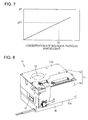
- Fig. 7 is a graph illustrating the relationship between an increase ⁇ F in the fluorescent intensity before and after heating and the concentration of biological particles.
- an increase ⁇ F1 in the fluorescent intensity is calculated from the difference in the fluorescent intensity before and after heating.
- the concentration N1 of biological particles corresponding to the calculated increase ⁇ F1 is found in accordance with a prepared relationship between the increase ⁇ F in the fluorescent intensity and the concentration N of biological particles.
- the correspondence relationship between the increase ⁇ F and the concentration N of biological particles is experimentally determined in advance.
- the particles 600 are removed from the collection substrate 510 (refreshing step).
- Fig. 8 is a perspective view illustrating the appearance of the particle detection device according to a first embodiment of the present invention.
- Fig. 9 is another perspective view illustrating the appearance of the particle detection device illustrated in Fig. 8 .
- Fig. 10 is an exploded view of the particle detection device illustrated in Fig. 8 .
- Fig. 11 is a perspective view illustrating an internal structure of the particle detection device illustrated in Fig. 8 .
- a particle detection device 10 includes a cabinet 11 serving as a housing, a fan 16, a collection unit 20, a fluorescence detection unit 30, and a cleaning unit 50.
- the cabinet 11 has a substantially rectangular parallelepiped shape and houses the collection unit 20, the fluorescence detection unit 30, and the cleaning unit 50.
- the cabinet 11 includes an upper cabinet 12 serving as a first housing and a lower cabinet 14 serving as a second housing.
- the lower cabinet 14 has a box shape having an opening on one side.
- the upper cabinet 12 has a flat-plate shape that closes the opening of the lower cabinet 14.
- the dimensions of the cabinet 11 are 60 mm x 50 mm (length and width of the upper cabinet 12) x 30 mm (height).
- the cabinet 11 has side surfaces 11m and 11n, which oppose each other.
- the side surface 11m is formed in the upper cabinet 12 and the side surface 11n is formed in the lower cabinet 14.
- the cabinet 11 has a collection barrel 15 serving as a barrel-shaped member, which is integrally formed with the cabinet 11.
- the collection barrel 15 opens at the side surface 11m and extends so as to form a cylindrical shape from the side surface 11m toward the side surface 11n.
- the collection barrel 15 surrounds an electrostatic stylus 22, which will be described later. Air that includes particles is guided toward a collection substrate 71, which is positioned so as to oppose the electrostatic stylus 22, through the collection barrel 15.
- Fig. 12 is a perspective view illustrating the particle detection device illustrated in Fig. 9 with the fan detached.
- the fan 16 is rotatable in the forward and reverse directions. When the fan 16 is rotated in the forward direction, air in the cabinet 11 is discharged to the outside of the cabinet 11 through the fan 16. When the fan 16 is rotated in the reverse direction, air is introduced from the outside of the cabinet 11 into the cabinet 11 through the fan 16.
- the fan 16 is attached to the side surface 11n of the cabinet 11.
- An opening 120 is formed at a position of the cabinet 11 where the fan 16 is attached.
- the opening 120 is opened so as to include a region opposite the collection barrel 15 (region indicated by a two-dot chain line 122 in Fig. 12 ) and a region opposite a brush 51 (region indicated by a two-dot chain line 121 in Fig. 12 ).
- the brush 51 will be described later.
- the region opposite the collection barrel 15 and the region opposite the brush 51 are continuous with each other.
- the fan 16 is used in the collecting step, for cooling in the heating step, and in the refreshing step.
- the size and the cost of the particle detection device 10 can be reduced.
- the collection unit 20 performs the collecting step having been described with reference to Fig. 2 , thereby collecting particles suspended in the air onto the collection substrate 71.
- the collection unit 20 includes a high-voltage power source 21 serving as a power unit and the electrostatic stylus 22 serving as a discharge electrode.
- the collection substrate 71 serves as a collection member. Mixed particles of biological particles and dust such as lint of chemical fiber are collected onto the collection substrate 71.
- the collection substrate 71 is formed of a glass plate. An electrically conductive transparent film is formed on a surface of the glass plate that attracts the particles.
- the collection substrate 71 is not necessarily formed of a glass plate and may be formed of ceramic or metal.
- the film is not necessarily transparent. For example, a metal film may be formed on the surface of the collection substrate 71 formed of ceramic or the like. When the collection substrate 71 is formed of metal, the film is not necessarily formed on the surface of the collection substrate 71.
- the high-voltage power source 21 is the power unit used to generate a potential difference between the collection substrate 71 and the electrostatic stylus 22.
- the electrostatic stylus 22 extends from the high-voltage power source 21, penetrates through the collection barrel 15, and reaches the inside of the collection barrel 15. In the collecting step, the collection substrate 71 opposes the electrostatic stylus 22. In the present embodiment, the electrostatic stylus 22 is electrically connected to a positive electrode of the high-voltage power source 21. The film formed on the collection substrate 71 is electrically connected to a negative electrode of the high-voltage power source 21.
- the film formed on the collection substrate 71 may be connected to a ground potential.
- the electrostatic stylus 22 may be electrically connected to the negative electrode of the high-voltage power source 21 and the film formed on the collection substrate 71 may be electrically connected to the positive electrode of the high-voltage power source 21.
- the collecting step when the fan 16 is rotated in the forward direction, air in the cabinet 11 is discharged and, at the same time, air outside the cabinet 11 is introduced toward the collection substrate 71 through the collection barrel 15.
- airborne particles around the electrostatic stylus 22 are positively charged.
- the positively charged particles are moved to the collection substrate 71 by electrostatic forces and attracted to the electrically conductive film, thereby being collected onto the collection substrate 71.
- the particles are collected onto the collection substrate 71 by electrostatic collection that utilizes electrostatic forces.
- the particles can be reliably held on the collection substrate 71 during detection of the particles, and after the particles have been detected, the particles can be easily removed from the collection substrate 71.
- the charged particles can be attracted to a very narrow region of the surface of the collection substrate 71 opposite the electrostatic stylus 22, the region corresponding to a region irradiated with the light emitting element, which will be described later.
- the fluorescence measuring step microorganisms having been attracted can be efficiently detected.
- the fluorescence detection unit 30 performs the fluorescence measuring steps (before and after heating) having been described with reference to Figs. 3 and 5 .
- the fluorescence detection unit 30 includes an excitation light source unit 31 and light receiving unit 41.
- the excitation light source unit 31 emits excitation light toward the particles collected on the collection substrate 71.
- the light receiving unit 41 receives fluorescence emitted from the particles as the particles are irradiated with the excitation light.
- the excitation light source unit 31 includes a light emitting element 32 serving as a light source, an excitation unit frame 33, a condensing lens 34, and a lens pressing member 35.
- the light receiving unit 41 includes a noise shield 42, an amplification circuit 43, a light receiving element 44, a light receiving unit frame 45, a Fresnel lens 46, and a lens pressing member 47.
- the light emitting element 32 uses, for example, a semiconductor laser or an LED (light emitting diode) element.
- the wavelength of light emitted from the light emitting element 32 may be in an ultraviolet range or a visible range as long as the light can excite biological particles and cause the biological particles to emit fluorescent.
- the light receiving element 44 uses, for example, a photodiode or an image sensor.
- the cleaning unit 50 performs the refreshing step having been described with reference to Fig. 6 , thereby removing the particles from the collection substrate 71.
- the cleaning unit 50 includes the brush 51 as a cleaning device, a brush securing portion 52 as a base portion, and a brush pressing member 53.
- the cleaning unit 50 is secured to and supported by the high-voltage power source 21.
- the cleaning unit 50 remains stationary during the refreshing step.
- the brush 51 is formed of a fiber assembly.
- the brush 51 is formed of an electrically conductive fiber assembly.
- the brush 51 is formed of, for example, a carbon fiber. It is preferable that the wire diameter of the fiber assembly of the brush 51 be from ⁇ 0.05 mm to ⁇ 0.2 mm.
- the brush 51 has a free end 51p and a supported end 51q (see Fig. 11 ).
- the supported end 51q is disposed at an end portion opposite to the free end 51p.
- the supported end 51q is supported by the brush securing portion 52 and the brush pressing member 53.
- the brush 51 hangs down with the supported end 51q at the top and the free end 51p at the bottom.
- the brush 51 is secured and supported at a refreshing position 93, which will be described later.
- the present invention is not limited to this.
- the collection device may be a flat plate-shaped wiper to be brought into contact with the surface of the collection substrate 71 or a nozzle, through which air is blown toward the surface of the collection substrate 71.
- the particle detection device 10 further includes a heater 76 serving as a heating unit and a movement mechanism 60.
- the heater 76 performs the heating step having been described with reference to Fig. 4 , thereby heating the particles collected on the collection substrate 71.
- the movement mechanism 60 moves the collection substrate 71 in the collecting step, the fluorescence measuring steps (before and after heating), the refreshing step, and the heating step.
- the movement mechanism 60 includes a motor holder 61, a rotating motor 62, a motor pressing member 63, and a rotating base 64.
- the rotating motor 62 serves as a rotatable drive unit.
- the rotating base 64 serves as an arm unit.
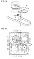
- Fig. 13 is a perspective view illustrating the rotating base of the movement mechanism.
- Fig. 14 is an exploded view of the rotating base illustrated in Fig. 13.
- Fig. 13 illustrates the rotating base 64 when seen from a rear side (side surface 11n side of the cabinet 11).
- Fig. 14 illustrates the rotating base 64 when seen from a front side (side surface 11m side of the cabinet 11).
- an output shaft of the rotating motor 62 is connected to the rotating base 64.
- the rotating base 64 rotates (in the forward and reverse directions) about a rotational axis 66 illustrated by a phantom line in Fig. 11 .
- the rotating base 64 is formed of a resin material.
- the rotating base 64 has the following portions: a central portion 67, a substrate supporting portion 68, a brush cleaning arm 81 serving as a cleaning device initializing member, and a sensing target portion 82.
- the central portion 67 is connected to the output shaft of the rotating motor 62.
- the central portion 67 is rotatably supported by the cabinet 11 about the rotational axis 66.
- the substrate supporting portion 68 extends from the central portion 67 in the radial direction of the rotational axis 66.
- the collection substrate 71 is attached to the tip of the substrate supporting portion 68.
- Part of the substrate supporting portion 68, the part being a part to which the collection substrate 71 is attached, has a frame shape. The details of the brush cleaning arm 81 and the sensing target portion 82 will be described later.
- the heater 76 is bonded to the rear surface of the collection substrate 71.
- the heater 76 is moved together with the collection substrate 71 when the rotating base 64 is rotated.
- a plurality of wires 111, 112, and 113 are connected to the heater 76.
- the wires 111, 112, and 113 include a power supply line of the heater 76 and a signal line of a sensor disposed in the heater 76.
- the wires 111, 112, and 113 are led to the outside of the cabinet 11 through a flexible printed circuit 96.
- Fig. 15 is a sectional view of the particle detection device in the collecting step and the heating step.
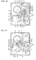
- Fig. 16 is a sectional view of the particle detection device in the fluorescence measuring steps (before and after heating).
- Fig. 17 is a sectional view of the particle detection device in the refreshing step.
- Figs. 15 to 17 are the sectional views of the particle detection device seen from the side surface 11n side of the cabinet 11.
- the collection substrate 71 is moved to a collection/heating position 91 illustrated in Fig. 15 as a first position in the collecting step and the heating step, moved to a detection position 92 illustrated in Fig. 16 as a second position in the fluorescence measuring steps (before and after heating), and moved to the refreshing position 93 illustrated in Fig. 17 as a third position in the refreshing step.
- the collection/heating position 91, the detection position 92, and the refreshing position 93 are separated from one another.
- the refreshing position 93 illustrated in Fig. 17 is a representative example of the refreshing position 93.
- the brush 51 is brought into contact with the surface of the collection substrate 71 while the collection substrate 71 is being moved, thereby removing the particles on the collection substrate 71.
- a movement range of the collection substrate 71 where the collection substrate 71 and the brush 51 are in contact with each other corresponds to the refreshing position 93.
- the collection substrate 71 is held in a single plane while being moved among the collection/heating position 91, the detection position 92, and the refreshing position 93.
- the collection substrate 71 is held in the single plane perpendicular to the rotational axis 66 while being moved among the collection/heating position 91, the detection position 92, and the refreshing position 93.
- the particle detection device 10 includes the movement mechanism 60, which held the collection substrate 71 in the single plane while moving the collection substrate 71 among the collection/heating position 91, the detection position 92, and the refreshing position 93. Since the collection substrate 71 is moved in the single plane in the present embodiment, positioning accuracy of the collection substrate 71 can be improved at the collection/heating position 91, the detection position 92, and the refreshing position 93. Furthermore, since the collection substrate 71 is not moved in the axial direction of the rotational axis 66, the entire height of the particle detection device 10 can be reduced.
- the collection/heating position 91, the detection position 92, and the refreshing position 93 are located on a circumference.
- the collection/heating position 91, the detection position 92, and the refreshing position 93 are arranged on the circumference about the rotational axis 66.
- the collection/heating position 91 is located between the detection position 92 and the refreshing position 93.
- the refreshing position 93 is located on a side of the collection/heating position 91 opposite to a side where the detection position 92 is located.
- the detection position 92, the collection/heating position 91, and the refreshing position 93 are arranged in this order.
- the moving distance of the collection substrate 71 between the detection position 92 and the refreshing position 93 is greater than that between the collection/heating position 91 and the refreshing position 93.
- the movement range of the collection substrate 71 about the rotational axis 66 among the collection/heating position 91, the detection position 92, and the refreshing position 93 is equal to or smaller than 180°.
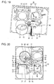
- FIG. 18 is a flowchart illustrating the flow of operation of the particle detection device according to the first embodiment of the present invention.
- a clockwise rotation about the rotational axis 66 in Figs. 15 to 17 is referred to as a forward direction and a counterclockwise rotation about the rotational axis 66 in Figs. 15 to 17 is referred to as a reverse direction.
- the collection substrate 71 is initially positioned at the collection/heating position 91 so as to perform the collecting step (S101). In so doing, air is introduced into the cabinet 11 by rotating the fan 16 in the forward direction, and airborne particles are collected onto the surface of the collection substrate 71 by generating a potential difference between the electrostatic stylus 22 and the collection substrate 71 using the high-voltage power source 21.
- the rotating base 64 is rotated in the forward direction by driving the rotating motor 62, thereby moving the collection substrate 71 from the collection/heating position 91 to the detection position 92 (S102).
- the excitation light source unit 31 emits excitation light toward the particles collected on the collection substrate 71, and fluorescence emitted from the particles irradiated with the excitation light is received by the light receiving unit 41. By doing this, the fluorescent intensity of the particles collected on the collection substrate 71 before heating is measured (S103).
- the rotating base 64 is rotated in the reverse direction by driving the rotating motor 62, thereby moving the collection substrate 71 from the detection position 92 to the collection/heating position 91 (S104).
- the particles collected on the collection substrate 71 are heated (S105).
- the collection substrate 71 is cooled (S106). In so doing, by driving the fan 16 in the reverse direction, the air is introduced into the cabinet 11, thereby facilitating cooling of the collection substrate 71.
- the rotating base 64 is rotated in the forward direction by driving the rotating motor 62, thereby moving the collection substrate 71 from the collection/heating position 91 to the detection position 92 (S107).
- the excitation light source unit 31 emits the excitation light toward the particles collected on the collection substrate 71, and the fluorescence emitted from the particles irradiated with the excitation light is received by the light receiving unit 41. By doing this, the fluorescent intensity of the particles collected on the collection substrate 71 after heating is measured (S108).
- the rotating base 64 is rotated in the reverse direction by driving the rotating motor 62, thereby moving the collection substrate 71 from the detection position 92 to the refreshing position 93.
- the rotating base 64 is rotated in the reverse direction and rotated in the forward direction at the refreshing position 93, thereby bringing the surface of the collection substrate 71 into contact with the brush 51. By doing this, the particles are removed from the collection substrate 71 (S109).
- the particles removed from the collection substrate 71 and flying in the air are discharged to the outside of the cabinet 11 through the opening 120.
- a filter be provided between the opening 120 and the fan 16.
- the refreshing step is performed by causing the cleaning unit 50 to remain stationary and moving the collection substrate 71. Accordingly, a separate movement mechanism for performing the refreshing step is not needed. Thus, the size and the cost of the particle detection device 10 can be reduced.
- the rotating base 64 is rotated in the forward direction by driving the rotating motor 62, thereby moving the collection substrate 71 from the refreshing position 93 to the collection/heating position 91 (S110).
- the biological particles are continuously detected.
- the structure of the particle detection device according to the first embodiment of the present invention having been described is summarized as follows. That is, the particle detection device 10 according to the present embodiment detects biological particles.
- the particle detection device 10 includes the collection unit 20, the fluorescence detection unit 30, and the cleaning unit 50.
- the collection unit 20 collects particles onto the collection substrate 71 that serves as the collection member.
- the fluorescence detection unit 30 emits excitation light toward the particles collected on the collection substrate 71 and receives fluorescence emitted from the particles.
- the cleaning unit 50 removes the particles from the collection substrate 71 at the refreshing position 93 as the third position.
- the refreshing position 93 is separated from the collection/heating position 91 as the first position and the detection position 92 as the second position.
- the particles are collected onto the collection substrate 71 by the collection unit 20.
- the fluorescence detection unit 30 is received by the fluorescence detection unit 30.
- the particle detection device 10 detects biological particles.
- the particle detection device 10 includes the collection unit 20, the fluorescence detection unit 30, the cleaning unit 50, and the movement mechanism 60.
- the collection unit 20 collects particles onto the collection substrate 71 that serves as the collection member.
- the fluorescence detection unit 30 emits excitation light toward the particles collected on the collection substrate 71 and receives fluorescence emitted from the particles.
- the cleaning unit 50 removes the particles from the collection substrate 71.
- the movement mechanism 60 moves the collection substrate 71 among the collection/heating position 91 as the first position, the detection position 92 as the second position, and the refreshing position 93 as the third position.
- the particles are collected onto the collection substrate 71 by the collection unit 20.
- the detection position 92 the fluorescence is received by the fluorescence detection unit 30.
- the cleaning unit 50 removes the particles from the collection substrate 71.
- the particle detection device 10 detects biological particles.
- the particle detection device 10 includes the collection unit 20, the fluorescence detection unit 30, and the cleaning unit 50.
- the collection unit 20 collects particles onto the collection substrate 71 that serves as the collection member.
- the fluorescence detection unit 30 emits excitation light toward the particles collected on the collection substrate 71 and receives fluorescence emitted from the particles.
- the cleaning unit 50 removes the particles from the collection substrate 71.
- the collection substrate 71 is rotated in the forward and reverse directions, thereby being moved among the collection/heating position 91 as the first position, the detection position 92 as the second position, and the refreshing position 93 as the third position.
- the particles are collected onto the collection substrate 71 by the collection unit 20.
- the detection position 92 the fluorescence is received by the fluorescence detection unit 30.
- the cleaning unit 50 removes the particles from the collection substrate 71.
- the cleaning unit 50 is provided for removing particles from the collection substrate 71. This allows the collection substrate 71 to be repeatedly used to detect biological particles. Thus, in comparison with the case where the collection substrate 71 is replaced every time a detection operation is performed, the cost required for particle detection can be reduced.
- the refreshing step in which particles are removed from the collection substrate 71, is performed at the refreshing position 93 separated from the collection/heating position 91 and the detection position 92.
- This can prevent the occurrence of the following situations: the particles having been removed from the collection substrate 71 are collected again to the collection substrate 71 in the next collecting step; and the particles having reached the detection position 92 from the collection substrate 71 adhere to optical systems such as the light emitting element 32 and the light receiving element 44.
- the collection/heating position 91 is located so as to separate the refreshing position 93 and the detection position 92 from each other in the present embodiment. This can effectively prevent the particles having been removed from the collection substrate 71 from reaching the detection position 92. For these reasons, biological particles can be highly accurately detected with the particle detection device 10 according to the present embodiment.
- the collection/heating position 91, the detection position 92, and the refreshing position 93 are arranged on a circumference.
- the collection substrate 71 is moved among these positions by being rotated.
- the collection unit 20, the fluorescence detection unit 30, and the cleaning unit 50 can be arranged in a compact space, and accordingly, the size of the particle detection device 10 can be reduced.
- the collection substrate 71 is rotated in the forward and reverse directions so as to be moved to the collection/heating position 91, detection position 92, and the refreshing position 93 in the present embodiment. This prevents entanglement of a plurality of wires led through the flexible printed circuit 96 and wires for electrostatic collection.
- the particle detection device 10 includes the heater 76 as the heating unit that heats particles collected on the collection substrate 71.
- Biological particles are detected by the difference between the intensity of fluorescence emitted from the particles before heating and the intensity of fluorescence emitted from the particles after heating.
- the fluorescent intensity is measured by the fluorescence detection unit 30.
- the collection substrate 71 is moved to the collection/heating position 91 as the first position.
- the heater 76 is moved together with the collection substrate 71 by the movement mechanism 60.
- the collection substrate 71 having been heated by the heater 76 is cooled by air introduced into the cabinet 11 by the fan 16.
- the heating step in which particles collected on the collection substrate 71 is heated, is performed at the same position (collection/heating position 91) as that of the collecting step, in which the particles are collected onto the collection substrate 71.
- the size of the particle detection device 10 can be reduced.
- the structure of the particle detection device 10 can be simplified.
- the components of the collection unit 20, the fluorescence detection unit 30, and the cleaning unit 50 are arranged in the circumferential direction about the rotational axis 66.
- the collection barrel 15 and the electrostatic stylus 22 oppose the collection/heating position 91.
- the high-voltage power source 21 and the cleaning unit 50 oppose the refreshing position 93.
- the light receiving unit 41 opposes the detection position 92.
- the collection barrel 15 and the light receiving unit 41 are adjacent to each other in the circumferential direction about the rotational axis 66.
- the excitation light source unit 31 is adjacent to the light receiving unit 41 on a side opposite to a side where the collection barrel 15 is disposed in the circumferential direction about the rotational axis 66. That is, the light receiving unit 41 is disposed between the excitation light source unit 31 and the collection barrel 15 in the circumferential direction about the rotational axis 66.
- the excitation light source unit 31 is disposed on a side opposite to a side where the collection barrel 15 is disposed with the rotational axis 66 interposed therebetween.
- the high-voltage power source 21 is adjacent to the collection barrel 15 on a side opposite to a side where the light receiving unit 41 is disposed in the circumferential direction about the rotational axis 66. That is, the collection barrel 15 is disposed between the high-voltage power source 21 and the light receiving unit 41 in the circumferential direction about the rotational axis 66.
- the high-voltage power source 21 is disposed on a side opposite to a side where the light receiving unit 41 is disposed with the rotational axis 66 interposed therebetween.
- the high-voltage power source 21 and the excitation light source unit 31 are adjacent to each other in the circumferential direction about the rotational axis 66.
- the collection barrel 15, the light receiving unit 41, and the high-voltage power source 21 are superposed with the movement range of the collection substrate 71 about the rotational axis 66.
- the excitation light source unit 31 is shifted from the movement range of the collection substrate 71 about the rotational axis 66.
- the excitation light source unit 31 is disposed opposite to the collection barrel 15 relative to the light receiving unit 41 in the movement direction of the collection substrate 71. With such a structure, an increase in the distance between the collection/heating position 91 and the detection position 92 due to arrangement of the excitation light source unit 31 is prevented.
- the cleaning unit 50 When seen in the axial direction of the rotational axis 66, the cleaning unit 50 is superposed with the high-voltage power source 21. More specifically, the brush securing portion 52 of the cleaning unit 50 is attached to the high-voltage power source 21.
- the excitation light source unit 31 and the light receiving unit 41 respectively have a height H1 (length in the axial direction of the rotational axis 66) and a height H2.
- the high-voltage power source 21 has a height H3.
- the height H3 is smaller than the height H1 and the height H2, and the height H1 is greater than the height H2 (H3 ⁇ H2 ⁇ H1).
- the cleaning unit 50 is superposed with the high-voltage power source 21, which has the smallest height among the excitation light source unit 31, the light receiving unit 41, and the high-voltage power source 21.
- the components of the collection unit 20, the fluorescence detection unit 30, and the cleaning unit 50 are efficiently arranged in a limited space in the cabinet 11.
- the cleaning unit 50 and the collection barrel 15 are adjacent to each other in the circumferential direction about the rotational axis 66.
- the fan 16 can be used in the collecting step, for cooling in the heating step, and in the refreshing step.
- Fig. 19 is a perspective view illustrating an internal structure of the particle detection device. Referring to Fig. 19 , the collection barrel 15 and the movement mechanism 60 are provided so as to separate the light receiving unit 41 and the excitation light source unit 31 from the cleaning unit 50.
- Such a structure can effectively reduce a situation in which particles having been removed from the collection substrate 71 at the refreshing position 93 reach the detection position 92. Furthermore, there is no need of providing partitions in the cabinet 11 in order to prevent the particles from reaching from the refreshing position 93 to the detection position 92, and accordingly, the collection/heating position 91, the detection position 92, and the refreshing position 93 can be located in a single space in the cabinet 11. Thus, the size of the particle detection device 10 can be reduced.
- the particle detection device 10 includes the brush cleaning arm 81 serving as the cleaning device initializing member. The particles that adhere to the brush 51 are removed by the brush cleaning arm 81.
- the brush cleaning arm 81 is integrated with the rotating base 64.
- the brush cleaning arm 81 is moved together with the collection substrate 71 when the rotating base 64 is rotated.
- the brush cleaning arm 81 extends in the radial direction of the rotational axis 66 from the central portion 67 of the rotating base 64. The particles adhering to the brush 51 are removed by rotating the brush cleaning arm 81 while the brush cleaning arm 81 is in contact with the free end 51p of the brush 51.
- the brush cleaning arm 81 is disposed at a position shifted from the substrate supporting portion 68 in the circumferential direction about the rotational axis 66. As illustrated in Fig. 16 , when the collection substrate 71 has been moved to the detection position 92, the brush cleaning arm 81 is positioned between the collection substrate 71 and the brush 51.
- Figs. 20 to 22 are sectional views illustrating the movements of the collection substrate and the brush cleaning arm in the refreshing step.
- Fig. 22 an end of the movement range of the collection substrate 71 in the refreshing step is illustrated.
- the rotating base 64 is rotated in the reverse direction, thereby moving the collection substrate 71 from the detection position 92 to the refreshing position 93.
- the particles adhering to the brush 51 are removed initially by moving the brush cleaning arm 81 in the reverse direction while the brush cleaning arm 81 is in contact with the free end 51p of the brush 51.
- the particles having been removed from the brush 51 are collected from the refreshing position 93 to the outside of the cabinet 11 by driving the fan 16 in the forward direction.
- the rotating base 64 is further rotated in the reverse direction so as to cause the surface of the collection substrate 71 to be brought into contact with the brush 51, thereby removing the particles from the collection substrate 71.
- the rotating base 64 is rotated in the forward direction so as to cause the surface of the collection substrate 71 to be brought into contact with the brush 51 again, thereby removing the particles from the collection substrate 71.
- the brush cleaning arm 81 when the collection substrate 71 has been moved to the detection position 92, the brush cleaning arm 81 is positioned between the collection substrate 71 and the brush 51. Thus, the brush cleaning arm 81 is brought into contact with the brush 51 before the collection substrate 71 is brought into contact with the brush 51. Accordingly, the collection substrate 71 can be cleaned by the brush 51, which has been refreshed with the brush cleaning arm 81. Thus, the particles can be efficiently removed from the collection substrate 71.
- the brush cleaning arm 81 is integrated with the rotating base 64, to which the collection substrate 71 is attached. With such a structure, a separate movement mechanism for moving the brush cleaning arm 81 is not required. Thus, the size and the cost of the particle detection device 10 can be reduced.
- a particle capturing portion having adhesiveness may be provided in the cabinet 11.
- the particle capturing portion is formed of, for example, an adhesive sheet.
- the particle capturing portion is provided at the refreshing position 93 or a position between the refreshing position 93 and the collection/heating position 91.
- Fig. 23 illustrates height relationships among the brush, the brush cleaning arm, and the collection substrate.
- the brush cleaning arm 81 and the collection substrate 71 respectively have top surfaces 81a and 71a to be in contact with the free end 51p of the brush 51.
- H6 the height of the free end 51p of the brush 51
- H7 the height of the top surface 81a of the brush cleaning arm 81
- H8 the height of the top surface 71a of the collection substrate 71
- the particle detection device 10 includes a position sensor 77, a position sensor 78, and the sensing target portion 82.
- the position sensors 77 and 78 serve as position detection units that detect the position of the collection substrate 71.
- the position sensors 77 and 78 detect the position of the collection substrate 71 by detecting that the sensing target portion 82 comes to the proximity of the position sensor 77 or 78.
- the position sensors 77 and 78 are attached to inner walls of the cabinet 11.
- the position sensors 77 and 78 are provided in a single plane perpendicular to the rotational axis 66. When seen in the axial direction of the rotational axis 66, the position sensor 77 is disposed between the collection/heating position 91 and the detection position 92, and the position sensor 78 is disposed between the collection/heating position 91 and the refreshing position 93.
- the sensing target portion 82 is integrated with the rotating base 64.
- the sensing target portion 82 is moved together with the collection substrate 71 when the rotating base 64 is rotated.
- the sensing target portion 82 is provided at the tip of the brush cleaning arm 81 that extends from the central portion 67 of the rotating base 64 in the radial direction of the rotational axis 66.
- a controller (not shown) detects that, when the position sensor 78 detects that the sensing target portion 82 comes to the proximity of the position sensor 78, the collection substrate 71 is positioned at the collection/heating position 91. At this time, the controller issues a command to the collection unit 20 and the fan 16 so as to start collection of particles onto the collection substrate 71. Furthermore, the controller detects that, when the position sensor 77 detects that the sensing target portion 82 comes to the proximity of the position sensor 77, the collection substrate 71 is positioned at the detection position 92. At this time, the controller issues an instruction to the fluorescence detection unit 30 so as to start detection of biological particles.
- the particle detection device 10 includes a projecting portion 19, which is disposed at the end of the movement range of the movement mechanism 60 and serves as a regulating member that regulates the movement of the movement mechanism 60.
- the projecting portion 19 projects from an inner wall of the cabinet 11.
- the projecting portion 19 is adjacent to the detection position 92.
- the particle detection device 10 may be used as a single device that detects biological particles, or may be incorporated in a home appliance such as an air cleaner, an air conditioner, a humidifier, a dehumidifier, a cleaner, a refrigerator, or a television set.
- a home appliance such as an air cleaner, an air conditioner, a humidifier, a dehumidifier, a cleaner, a refrigerator, or a television set.
- Fig. 24 is a plan view illustrating a particle detection device according to a second embodiment of the present invention.
- Fig. 25 is a side view of the particle detection device illustrated in Fig. 24 .
- the particle detection device according to the present embodiment basically has similar structures compared to those of the particle detection device 10 according to the first embodiment. Duplicate structures are not repeatedly described in the following description.
- the collection/heating position 91, the detection position 92, and the refreshing position 93 are arranged on a line.
- the collection substrate 71 attached to a movement mechanism (not shown) is moved among the collection/heating position 91, the detection position 92, and the refreshing position 93 while being reciprocated in a direction indicated by a double-headed arrow 131.
- a movement mechanism not shown
- the reciprocation of the collection substrate 71 in a double-headed arrow 132 direction at the refreshing position 93 particles collected on the collection substrate 71 are removed.
- the collection/heating position 91 is located between the detection position 92 and the refreshing position 93.
- the refreshing position 93 is located on a side of the collection/heating position 91 opposite to a side where the detection position 92 is located.
- the detection position 92, the collection/heating position 91, and the refreshing position 93 are arranged in this order.
- the collection/heating position 91, the detection position 92, and the refreshing position 93 are arranged on a line.
- the distance between the detection position 92 and the refreshing position 93 can be increased. This can effectively prevent a situation in which particles having been removed from the collection substrate 71 at the refreshing position 93 from reaching the detection position 92.
- the collection unit 20, the fluorescence detection unit 30, and the cleaning unit 50 are configured such that the detection position 92 is located between the collection/heating position 91 and the refreshing position 93 in the movement direction of the collection substrate 71.
- the present invention is mainly used as a device that detects biological particles such as pollen, microorganisms, and molds.
Landscapes
- Health & Medical Sciences (AREA)
- Chemical & Material Sciences (AREA)
- Life Sciences & Earth Sciences (AREA)
- Immunology (AREA)
- Physics & Mathematics (AREA)
- General Physics & Mathematics (AREA)
- Biochemistry (AREA)
- General Health & Medical Sciences (AREA)
- Analytical Chemistry (AREA)
- Pathology (AREA)
- Dispersion Chemistry (AREA)
- Molecular Biology (AREA)
- Nuclear Medicine, Radiotherapy & Molecular Imaging (AREA)
- Engineering & Computer Science (AREA)
- Biomedical Technology (AREA)
- Chemical Kinetics & Catalysis (AREA)
- Optics & Photonics (AREA)
- Investigating, Analyzing Materials By Fluorescence Or Luminescence (AREA)
Abstract
Description
- The present invention generally relates to a particle detection device and particularly relates to a particle detection device that detects biological particles.
- As a related-art particle detection device, Japanese Unexamined Patent Application Publication No.
2002-357532 - The measuring device disclosed in
Patent Literature 1 includes a suspended particulate matter collection unit that collects suspended particulate matter in a sample gas onto filter paper, a suspended particulate matter detection unit that irradiates the suspended particulate matter on the filter paper with β-rays, measures the amount of β-ray transmission so as to detect the suspended particulate matter, and a pollen detection unit that irradiates the pollen contained in the suspended particulate matter with ultraviolet rays and measure the intensity of generated fluorescence so as to measure the amount of the pollen. The filter paper to which the suspended particulate matter has been collected is transported between the suspended particulate matter collection unit and a region where the suspended particulate matter detection unit and the pollen detection unit are disposed by using a filter paper transport mechanism, which includes rollers and motors combined to one another. - PTL 1: Japanese Unexamined Patent Application Publication No.
2002-357532 - As disclosed in the above-described Patent Literature, a known detection device measures the number of particles by irradiating the particles in air with ultraviolet rays and receiving fluorescence emitted from the particles. In such a particle detection device, a collection member such as a substrate is used to collect particles. However, when such a collection member is replaced with a new collection member every time measurement is performed, there is a problem in that the cost of particle detection is increased.
- As a measure to solve such a problem, the collection member may be repeatedly used by cleaning the collection member when particle detection is completed. However, there is a concern over adverse effects on accuracy, with which the particles are detected, in the case where the particles removed from the collection member by cleaning are collected again to the collection member or adhere to optical systems for irradiation of ultraviolet rays or receiving fluorescence.
- Accordingly, an object of the present invention is to solve the above-described problem and is to provide a particle detection device in which particles are highly accurately detected.
- A particle detection device according to the present invention detects a biological particle. The particle detection device includes a collection unit that collects a particle to a collection member, a fluorescence detection unit that emits excitation light toward the particle collected to the collection member and receives fluorescence emitted from the particle, and a cleaning unit that removes the particle from the collection member at a third position separated from a first position and a second position. The particle is collected by the collection unit to the collection member at the first position. The fluorescence is received by the fluorescence detection unit at the second position.
- In the particle detection device structured as described above, the particle is removed from the collection member by the cleaning unit at the third position separated from the first position and the second position. This can reduce a situation, in which the particle having been removed from the particle reaches the first position or the second position. Accordingly, the particle detection device in which the particle is highly accurately detected can be realized.
- Preferably, the collection member is moved among the first position, the second position, and the third position. In a movement direction of the collection member, when seen from the first position, the third position is located on a side opposite to a side where the second position is located.
- In the particle detection device structured as described above, the third position, where the particle is removed from the collection member, and the second position, where the fluorescence is received by the fluorescence detection unit, are separated from each other. Thus, the particle can be highly accurately detected.
- Preferably, the first position, the second position, and the third position are arranged on a circumference. In the particle detection device structured as described above, the collection unit, the fluorescence detection unit, and the cleaning unit can be arranged in a compact space.
- Preferably, the first position, the second position, and the third position are arranged on a line. In the particle detection device structured as described above, the third position, where the particle is removed from the collection member, and the second position, where the fluorescence is received by the fluorescence detection unit, are further separated from each other. Thus, the particle can be more highly accurately detected.
- Preferably, the collection member is moved among the first position, the second position, and the third position. A moving distance of the collection member between the second position and the third position is greater than a moving distance of the collection member between the first position and the third position.
- In the particle detection device structured as described above, the third position, where the particle is removed from the collection member, and the second position, where the fluorescence is received by the fluorescence detection unit, are separated from each other. Thus, the particle can be highly accurately detected.
- Preferably, the particle detection device further includes a heating unit that heats the particle, which has been collected to the collection member, at the first position. More preferably, the heating unit is disposed in the collection member. In the particle detection device structured as described above, by heating the particle collected to the collection member, a biological particle can be highly accurately detected.
- As described above, according to the present invention, the particle detection device that highly accurately detects the particle can be provided.
-
- [
Fig. 1] Fig. 1 includes graphs illustrating a change in fluorescent intensity of biological particles before and after heating and a change in fluorescent intensity of dust before and after heating. - [
Fig. 2] Fig. 2 illustrates a collecting step in biological particle detection. - [
Fig. 3] Fig. 3 illustrates a fluorescence measuring step (before heating) in the biological particle detection. - [
Fig. 4] Fig. 4 illustrates a heating step in the biological particle detection. - [
Fig. 5] Fig. 5 illustrates a fluorescence measuring step (after heating) in the biological particle detection. - [
Fig. 6] Fig. 6 illustrates a refreshing step in the biological particle detection. - [
Fig. 7] Fig. 7 is a graph illustrating the relationship between an increase ΔF in the fluorescent intensity before and after heating and the concentration of biological particles. - [
Fig. 8] Fig. 8 is a perspective view illustrating the appearance of a particle detection device according to a first embodiment of the present invention. - [
Fig. 9] Fig. 9 is another perspective view illustrating the appearance of the particle detection device illustrated inFig. 8 . - [
Fig. 10] Fig. 10 is an exploded view of the particle detection device illustrated inFig. 8 . - [
Fig. 11] Fig. 11 is a perspective view illustrating an internal structure of the particle detection device illustrated inFig. 8 . - [
Fig. 12] Fig. 12 is a perspective view illustrating the particle detection device illustrated inFig. 9 with a fan detached. - [
Fig. 13] Fig. 13 is a perspective view illustrating a rotating base of a movement mechanism. - [
Fig. 14] Fig. 14 is an exploded view of the rotating base illustrated inFig. 13 . - [
Fig. 15] Fig. 15 is a sectional view of the particle detection device in the collecting step and the heating step. - [
Fig. 16] Fig. 16 is a sectional view of the particle detection device in the fluorescence measuring steps (before and after heating). - [
Fig. 17] Fig. 17 is a sectional view of the particle detection device in the refreshing step. - [
Fig. 18] Fig. 18 is a flowchart illustrating a flow of operation of the particle detection device according to the first embodiment of the present invention. - [
Fig. 19] Fig. 19 is a perspective view illustrating an internal structure of the particle detection device. - [
Fig. 20] Fig. 20 is a sectional view illustrating movements of a collection substrate and a brush cleaning arm in the refreshing step. - [
Fig. 21] Fig. 21 is another sectional view illustrating the movements of the collection substrate and the brush cleaning arm in the refreshing step. - [
Fig. 22] Fig. 22 is yet another sectional view illustrating the movements of the collection substrate and the brush cleaning arm in the refreshing step. - [
Fig. 23] Fig. 23 illustrates height relationships among a brush, the brush cleaning arm, and the collection substrate. - [
Fig. 24] Fig. 24 is a plan view illustrating a particle detection device according to a second embodiment of the present invention. - [
Fig. 25] Fig. 25 is a side view of the particle detection device illustrated inFig. 24 . - Embodiments of the present invention will be described with reference to the drawings. In the drawings to be referred to in the description below, the same components or components equal to the same components are denoted by the same reference numerals.
- A particle detection device according to the present embodiment detects biological particles such as pollen, microorganisms, and molds. The principle of detecting biological particles using the particle detection device according to the present embodiment is initially described.
-
Fig. 1 includes graphs illustrating a change in fluorescent intensity of biological particles before and after heating and a change in fluorescent intensity of dust before and after heating. - Airborne biological particles emit fluorescence when being irradiated with ultraviolet light or blue light. In air, however, other particles such as lint of chemical fiber (referred to as dust hereafter), which emit fluorescence similarly to biological particles, are also suspended. Thus, it is impossible to distinguish whether the light comes from biological particles or dust only by detecting fluorescence.
- When, as illustrated in
Fig. 1 , biological particles and dust are heated and changes in the fluorescent intensities (amount of fluorescence) thereof are measured before and after heating, the fluorescent intensity emitted from the dust is not changed by heating and the fluorescent intensity emitted from the biological particles is increased by heating. The particle detection device according to the present embodiment measures the fluorescent intensity of a mixed particle of biological particles and dust before and after heating, and obtains the difference between the fluorescent intensity before and after the heating, thereby determining the number of the biological particles. -
Figs. 2 to 6 illustrate steps of detecting biological particles. Referring toFig. 2 , particles are initially collected on a collection substrate 510 (collecting step). - In this step, the
collection substrate 510 is disposed opposite anelectrostatic stylus 530 and a potential difference is generated between thecollection substrate 510 and theelectrostatic stylus 530. When air is introduced toward thecollection substrate 510 by driving afan 500,airborne particles 600 around theelectrostatic stylus 530 are charged. The chargedparticles 600 are attracted to a surface of thecollection substrate 510 by electrostatic forces. Theparticles 600 collected on thecollection substrate 510 includesbiological particles 600A anddust 600B including, for example, lint of chemical fiber. - Next, referring to
Fig. 3 , the intensity of fluorescence emitted from theparticles 600 before heating is measured (fluorescence measuring step (before heating)). In this step, theparticles 600 collected on thecollection substrate 510 is irradiated with excitation light emitted thereto from alight emitting element 550 such as a semiconductor laser, and fluorescence emitted from theparticles 600 is received by alight receiving element 565 through alens 560. - Next, referring to
Fig. 4 , theparticles 600 collected on thecollection substrate 510 is heated by using aheater 520. After theparticles 600 have been heated, thecollection substrate 510 is cooled (heating step). - Referring to
Fig. 5 , next, the intensity of fluorescence emitted from theparticles 600 after heating is measured (fluorescence measuring step (after heating)). As has been described, the intensity of fluorescence emitted from thedust 600B is not changed by heating, and the intensity of fluorescence emitted from thebiological particles 600A is increased by heating. Thus, the fluorescent intensity measured in this step is greater than that measured in the fluorescence measuring step (before heating) illustrated inFig. 3 . -
Fig. 7 is a graph illustrating the relationship between an increase ΔF in the fluorescent intensity before and after heating and the concentration of biological particles. Referring toFig. 7 , an increase ΔF1 in the fluorescent intensity is calculated from the difference in the fluorescent intensity before and after heating. The concentration N1 of biological particles corresponding to the calculated increase ΔF1 is found in accordance with a prepared relationship between the increase ΔF in the fluorescent intensity and the concentration N of biological particles. The correspondence relationship between the increase ΔF and the concentration N of biological particles is experimentally determined in advance. - Referring to
Fig. 6 , next, when detection of the biological particles of theparticles 600 has been performed, theparticles 600 are removed from the collection substrate 510 (refreshing step). -
Fig. 8 is a perspective view illustrating the appearance of the particle detection device according to a first embodiment of the present invention.Fig. 9 is another perspective view illustrating the appearance of the particle detection device illustrated inFig. 8 .Fig. 10 is an exploded view of the particle detection device illustrated inFig. 8 .Fig. 11 is a perspective view illustrating an internal structure of the particle detection device illustrated inFig. 8 . - Referring to
Figs. 8 to 11 , aparticle detection device 10 according to the present embodiment includes acabinet 11 serving as a housing, afan 16, acollection unit 20, afluorescence detection unit 30, and acleaning unit 50. - The
cabinet 11 has a substantially rectangular parallelepiped shape and houses thecollection unit 20, thefluorescence detection unit 30, and thecleaning unit 50. In the present embodiment, thecabinet 11 includes anupper cabinet 12 serving as a first housing and alower cabinet 14 serving as a second housing. Thelower cabinet 14 has a box shape having an opening on one side. Theupper cabinet 12 has a flat-plate shape that closes the opening of thelower cabinet 14. As an example, the dimensions of thecabinet 11 are 60 mm x 50 mm (length and width of the upper cabinet 12) x 30 mm (height). - The
cabinet 11 has side surfaces 11m and 11n, which oppose each other. Theside surface 11m is formed in theupper cabinet 12 and theside surface 11n is formed in thelower cabinet 14. - The
cabinet 11 has acollection barrel 15 serving as a barrel-shaped member, which is integrally formed with thecabinet 11. Thecollection barrel 15 opens at theside surface 11m and extends so as to form a cylindrical shape from theside surface 11m toward theside surface 11n. Thecollection barrel 15 surrounds anelectrostatic stylus 22, which will be described later. Air that includes particles is guided toward acollection substrate 71, which is positioned so as to oppose theelectrostatic stylus 22, through thecollection barrel 15. -
Fig. 12 is a perspective view illustrating the particle detection device illustrated inFig. 9 with the fan detached. Referring toFigs. 9 and12 , thefan 16 is rotatable in the forward and reverse directions. When thefan 16 is rotated in the forward direction, air in thecabinet 11 is discharged to the outside of thecabinet 11 through thefan 16. When thefan 16 is rotated in the reverse direction, air is introduced from the outside of thecabinet 11 into thecabinet 11 through thefan 16. - The
fan 16 is attached to theside surface 11n of thecabinet 11. Anopening 120 is formed at a position of thecabinet 11 where thefan 16 is attached. Theopening 120 is opened so as to include a region opposite the collection barrel 15 (region indicated by a two-dot chain line 122 inFig. 12 ) and a region opposite a brush 51 (region indicated by a two-dot chain line 121 inFig. 12 ). Thebrush 51 will be described later. In theopening 120, the region opposite thecollection barrel 15 and the region opposite thebrush 51 are continuous with each other. - With this structure, the
fan 16 is used in the collecting step, for cooling in the heating step, and in the refreshing step. Thus, the size and the cost of theparticle detection device 10 can be reduced. - Referring to
Figs. 8 to 11 , thecollection unit 20 performs the collecting step having been described with reference toFig. 2 , thereby collecting particles suspended in the air onto thecollection substrate 71. Thecollection unit 20 includes a high-voltage power source 21 serving as a power unit and theelectrostatic stylus 22 serving as a discharge electrode. - The
collection substrate 71 serves as a collection member. Mixed particles of biological particles and dust such as lint of chemical fiber are collected onto thecollection substrate 71. Thecollection substrate 71 is formed of a glass plate. An electrically conductive transparent film is formed on a surface of the glass plate that attracts the particles. Thecollection substrate 71 is not necessarily formed of a glass plate and may be formed of ceramic or metal. The film is not necessarily transparent. For example, a metal film may be formed on the surface of thecollection substrate 71 formed of ceramic or the like. When thecollection substrate 71 is formed of metal, the film is not necessarily formed on the surface of thecollection substrate 71. - The high-
voltage power source 21 is the power unit used to generate a potential difference between thecollection substrate 71 and theelectrostatic stylus 22. - The
electrostatic stylus 22 extends from the high-voltage power source 21, penetrates through thecollection barrel 15, and reaches the inside of thecollection barrel 15. In the collecting step, thecollection substrate 71 opposes theelectrostatic stylus 22. In the present embodiment, theelectrostatic stylus 22 is electrically connected to a positive electrode of the high-voltage power source 21. The film formed on thecollection substrate 71 is electrically connected to a negative electrode of the high-voltage power source 21. - In the case where the
electrostatic stylus 22 is electrically connected to the positive electrode of the high-voltage power source 21, the film formed on thecollection substrate 71 may be connected to a ground potential. Alternatively, theelectrostatic stylus 22 may be electrically connected to the negative electrode of the high-voltage power source 21 and the film formed on thecollection substrate 71 may be electrically connected to the positive electrode of the high-voltage power source 21. - In the collecting step, when the
fan 16 is rotated in the forward direction, air in thecabinet 11 is discharged and, at the same time, air outside thecabinet 11 is introduced toward thecollection substrate 71 through thecollection barrel 15. In so doing, by generating the potential difference between theelectrostatic stylus 22 and thecollection substrate 71 by using the high-voltage power source 21, airborne particles around theelectrostatic stylus 22 are positively charged. The positively charged particles are moved to thecollection substrate 71 by electrostatic forces and attracted to the electrically conductive film, thereby being collected onto thecollection substrate 71. - As described above, in the
particle detection device 10 according to the present embodiment, the particles are collected onto thecollection substrate 71 by electrostatic collection that utilizes electrostatic forces. In this case, the particles can be reliably held on thecollection substrate 71 during detection of the particles, and after the particles have been detected, the particles can be easily removed from thecollection substrate 71. - By using the needle-shaped
electrostatic stylus 22 as the discharge electrode, the charged particles can be attracted to a very narrow region of the surface of thecollection substrate 71 opposite theelectrostatic stylus 22, the region corresponding to a region irradiated with the light emitting element, which will be described later. Thus, in the fluorescence measuring step, microorganisms having been attracted can be efficiently detected. - The
fluorescence detection unit 30 performs the fluorescence measuring steps (before and after heating) having been described with reference toFigs. 3 and5 . Thefluorescence detection unit 30 includes an excitationlight source unit 31 andlight receiving unit 41. The excitationlight source unit 31 emits excitation light toward the particles collected on thecollection substrate 71. Thelight receiving unit 41 receives fluorescence emitted from the particles as the particles are irradiated with the excitation light. - The excitation
light source unit 31 includes alight emitting element 32 serving as a light source, anexcitation unit frame 33, a condensinglens 34, and alens pressing member 35. Thelight receiving unit 41 includes anoise shield 42, anamplification circuit 43, alight receiving element 44, a light receivingunit frame 45, aFresnel lens 46, and alens pressing member 47. Thelight emitting element 32 uses, for example, a semiconductor laser or an LED (light emitting diode) element. The wavelength of light emitted from thelight emitting element 32 may be in an ultraviolet range or a visible range as long as the light can excite biological particles and cause the biological particles to emit fluorescent. Thelight receiving element 44 uses, for example, a photodiode or an image sensor. - The
cleaning unit 50 performs the refreshing step having been described with reference toFig. 6 , thereby removing the particles from thecollection substrate 71. Thecleaning unit 50 includes thebrush 51 as a cleaning device, abrush securing portion 52 as a base portion, and abrush pressing member 53. Thecleaning unit 50 is secured to and supported by the high-voltage power source 21. Thecleaning unit 50 remains stationary during the refreshing step. - The
brush 51 is formed of a fiber assembly. Thebrush 51 is formed of an electrically conductive fiber assembly. Thebrush 51 is formed of, for example, a carbon fiber. It is preferable that the wire diameter of the fiber assembly of thebrush 51 be from φ0.05 mm to φ0.2 mm. - The
brush 51 has afree end 51p and a supportedend 51q (seeFig. 11 ). The supportedend 51q is disposed at an end portion opposite to thefree end 51p. The supportedend 51q is supported by thebrush securing portion 52 and thebrush pressing member 53. Thebrush 51 hangs down with the supportedend 51q at the top and thefree end 51p at the bottom. Thebrush 51 is secured and supported at arefreshing position 93, which will be described later. By moving thecollection substrate 71 while thefree end 51p of thebrush 51 is in contact with the surface of thecollection substrate 71, the particles are removed from thecollection substrate 71. - Although a collection device that removes particles from the
collection substrate 71 uses thebrush 51 in the present embodiment, the present invention is not limited to this. For example, the collection device may be a flat plate-shaped wiper to be brought into contact with the surface of thecollection substrate 71 or a nozzle, through which air is blown toward the surface of thecollection substrate 71. - The
particle detection device 10 further includes aheater 76 serving as a heating unit and amovement mechanism 60. - The
heater 76 performs the heating step having been described with reference toFig. 4 , thereby heating the particles collected on thecollection substrate 71. - The
movement mechanism 60, to which thecollection substrate 71 is attached, moves thecollection substrate 71 in the collecting step, the fluorescence measuring steps (before and after heating), the refreshing step, and the heating step. Themovement mechanism 60 includes amotor holder 61, arotating motor 62, amotor pressing member 63, and a rotatingbase 64. Therotating motor 62 serves as a rotatable drive unit. The rotatingbase 64 serves as an arm unit. -
Fig. 13 is a perspective view illustrating the rotating base of the movement mechanism.Fig. 14 is an exploded view of the rotating base illustrated inFig. 13. Fig. 13 illustrates the rotatingbase 64 when seen from a rear side (side surface 11n side of the cabinet 11).Fig. 14 illustrates the rotatingbase 64 when seen from a front side (side surface 11m side of the cabinet 11). - Referring to
Figs. 11 ,13 , and14 , an output shaft of therotating motor 62 is connected to the rotatingbase 64. As therotating motor 62 rotates, the rotatingbase 64 rotates (in the forward and reverse directions) about arotational axis 66 illustrated by a phantom line inFig. 11 . - The rotating
base 64 is formed of a resin material. The rotatingbase 64 has the following portions: acentral portion 67, asubstrate supporting portion 68, abrush cleaning arm 81 serving as a cleaning device initializing member, and asensing target portion 82. - The
central portion 67 is connected to the output shaft of therotating motor 62. Thecentral portion 67 is rotatably supported by thecabinet 11 about therotational axis 66. Thesubstrate supporting portion 68 extends from thecentral portion 67 in the radial direction of therotational axis 66. Thecollection substrate 71 is attached to the tip of thesubstrate supporting portion 68. Part of thesubstrate supporting portion 68, the part being a part to which thecollection substrate 71 is attached, has a frame shape. The details of thebrush cleaning arm 81 and thesensing target portion 82 will be described later. - The
heater 76 is bonded to the rear surface of thecollection substrate 71. Theheater 76 is moved together with thecollection substrate 71 when the rotatingbase 64 is rotated. A plurality ofwires heater 76. Thewires heater 76 and a signal line of a sensor disposed in theheater 76. Thewires cabinet 11 through a flexible printedcircuit 96. -
Fig. 15 is a sectional view of the particle detection device in the collecting step and the heating step.Fig. 16 is a sectional view of the particle detection device in the fluorescence measuring steps (before and after heating).Fig. 17 is a sectional view of the particle detection device in the refreshing step.Figs. 15 to 17 are the sectional views of the particle detection device seen from theside surface 11n side of thecabinet 11. - Referring to
Figs. 15 to 17 , in theparticle detection device 10 according to the present embodiment, thecollection substrate 71 is moved to a collection/heating position 91 illustrated inFig. 15 as a first position in the collecting step and the heating step, moved to adetection position 92 illustrated inFig. 16 as a second position in the fluorescence measuring steps (before and after heating), and moved to therefreshing position 93 illustrated inFig. 17 as a third position in the refreshing step. The collection/heating position 91, thedetection position 92, and therefreshing position 93 are separated from one another. - It is noted that the
refreshing position 93 illustrated inFig. 17 is a representative example of therefreshing position 93. In the actual refreshing step, thebrush 51 is brought into contact with the surface of thecollection substrate 71 while thecollection substrate 71 is being moved, thereby removing the particles on thecollection substrate 71. Thus, a movement range of thecollection substrate 71 where thecollection substrate 71 and thebrush 51 are in contact with each other corresponds to therefreshing position 93. - The
collection substrate 71 is held in a single plane while being moved among the collection/heating position 91, thedetection position 92, and therefreshing position 93. Thecollection substrate 71 is held in the single plane perpendicular to therotational axis 66 while being moved among the collection/heating position 91, thedetection position 92, and therefreshing position 93. - That is, the
particle detection device 10 according to the present embodiment includes themovement mechanism 60, which held thecollection substrate 71 in the single plane while moving thecollection substrate 71 among the collection/heating position 91, thedetection position 92, and therefreshing position 93. Since thecollection substrate 71 is moved in the single plane in the present embodiment, positioning accuracy of thecollection substrate 71 can be improved at the collection/heating position 91, thedetection position 92, and therefreshing position 93. Furthermore, since thecollection substrate 71 is not moved in the axial direction of therotational axis 66, the entire height of theparticle detection device 10 can be reduced. - The collection/
heating position 91, thedetection position 92, and therefreshing position 93 are located on a circumference. The collection/heating position 91, thedetection position 92, and therefreshing position 93 are arranged on the circumference about therotational axis 66. In the movement direction of thecollection substrate 71, the collection/heating position 91 is located between thedetection position 92 and therefreshing position 93. In other words, in the movement direction of thecollection substrate 71, therefreshing position 93 is located on a side of the collection/heating position 91 opposite to a side where thedetection position 92 is located. In the movement direction of thecollection substrate 71, thedetection position 92, the collection/heating position 91, and therefreshing position 93 are arranged in this order. - The moving distance of the
collection substrate 71 between thedetection position 92 and therefreshing position 93 is greater than that between the collection/heating position 91 and therefreshing position 93. The movement range of thecollection substrate 71 about therotational axis 66 among the collection/heating position 91, thedetection position 92, and therefreshing position 93 is equal to or smaller than 180°. - Next, operation of the
particle detection device 10 according to the present embodiment is described.Fig. 18 is a flowchart illustrating the flow of operation of the particle detection device according to the first embodiment of the present invention. - In the following description, a clockwise rotation about the
rotational axis 66 inFigs. 15 to 17 is referred to as a forward direction and a counterclockwise rotation about therotational axis 66 inFigs. 15 to 17 is referred to as a reverse direction. - Referring to
Figs. 15 and18 , thecollection substrate 71 is initially positioned at the collection/heating position 91 so as to perform the collecting step (S101). In so doing, air is introduced into thecabinet 11 by rotating thefan 16 in the forward direction, and airborne particles are collected onto the surface of thecollection substrate 71 by generating a potential difference between theelectrostatic stylus 22 and thecollection substrate 71 using the high-voltage power source 21. - Next, referring to
Figs. 16 and18 , the rotatingbase 64 is rotated in the forward direction by driving therotating motor 62, thereby moving thecollection substrate 71 from the collection/heating position 91 to the detection position 92 (S102). Next, the excitationlight source unit 31 emits excitation light toward the particles collected on thecollection substrate 71, and fluorescence emitted from the particles irradiated with the excitation light is received by thelight receiving unit 41. By doing this, the fluorescent intensity of the particles collected on thecollection substrate 71 before heating is measured (S103). - Next, referring to
Figs. 15 and18 , the rotatingbase 64 is rotated in the reverse direction by driving therotating motor 62, thereby moving thecollection substrate 71 from thedetection position 92 to the collection/heating position 91 (S104). Next, by supplying power to theheater 76, the particles collected on thecollection substrate 71 are heated (S105). Next, by stopping the power supply to theheater 76, thecollection substrate 71 is cooled (S106). In so doing, by driving thefan 16 in the reverse direction, the air is introduced into thecabinet 11, thereby facilitating cooling of thecollection substrate 71. - Next, referring to
Figs. 16 and18 , the rotatingbase 64 is rotated in the forward direction by driving therotating motor 62, thereby moving thecollection substrate 71 from the collection/heating position 91 to the detection position 92 (S107). Next, the excitationlight source unit 31 emits the excitation light toward the particles collected on thecollection substrate 71, and the fluorescence emitted from the particles irradiated with the excitation light is received by thelight receiving unit 41. By doing this, the fluorescent intensity of the particles collected on thecollection substrate 71 after heating is measured (S108). - Next, referring to
Figs. 17 and18 , the rotatingbase 64 is rotated in the reverse direction by driving therotating motor 62, thereby moving thecollection substrate 71 from thedetection position 92 to therefreshing position 93. The rotatingbase 64 is rotated in the reverse direction and rotated in the forward direction at therefreshing position 93, thereby bringing the surface of thecollection substrate 71 into contact with thebrush 51. By doing this, the particles are removed from the collection substrate 71 (S109). - In the refreshing step, by driving the
fan 16 in the forward direction, the particles removed from thecollection substrate 71 and flying in the air are discharged to the outside of thecabinet 11 through theopening 120. In order to collect the particles discharged to the outside of thecabinet 11 through theopening 120, it is preferable that a filter be provided between theopening 120 and thefan 16. - In so doing, as the
collection substrate 71 approaches from the collection/heating position 91 illustrated inFig. 15 to therefreshing position 93 illustrated inFig. 17 , a region where thecollection substrate 71 and thecollection barrel 15 are superposed with each other is decreased. Accordingly, the area of an opening of thecollection barrel 15 as an air inlet is increased. Thus, the particles can be efficiently collected at the outside thecabinet 11. In contrast, in the collecting step, the area of the opening of thecollection barrel 15 is reduced by being blocked by thecollection substrate 71. Thus, losses in air introduction can be reduced. - In the present embodiment, the refreshing step is performed by causing the
cleaning unit 50 to remain stationary and moving thecollection substrate 71. Accordingly, a separate movement mechanism for performing the refreshing step is not needed. Thus, the size and the cost of theparticle detection device 10 can be reduced. - Referring to
Figs. 15 and18 , the rotatingbase 64 is rotated in the forward direction by driving therotating motor 62, thereby moving thecollection substrate 71 from therefreshing position 93 to the collection/heating position 91 (S110). By repeating the above-described steps S101 to S110, the biological particles are continuously detected. - The structure of the particle detection device according to the first embodiment of the present invention having been described is summarized as follows. That is, the
particle detection device 10 according to the present embodiment detects biological particles. Theparticle detection device 10 includes thecollection unit 20, thefluorescence detection unit 30, and thecleaning unit 50. Thecollection unit 20 collects particles onto thecollection substrate 71 that serves as the collection member. Thefluorescence detection unit 30 emits excitation light toward the particles collected on thecollection substrate 71 and receives fluorescence emitted from the particles. Thecleaning unit 50 removes the particles from thecollection substrate 71 at therefreshing position 93 as the third position. Therefreshing position 93 is separated from the collection/heating position 91 as the first position and thedetection position 92 as the second position. At the collection/heating position 91, the particles are collected onto thecollection substrate 71 by thecollection unit 20. At thedetection position 92, the fluorescence is received by thefluorescence detection unit 30. - In addition, the
particle detection device 10 according to the present embodiment detects biological particles. Theparticle detection device 10 includes thecollection unit 20, thefluorescence detection unit 30, thecleaning unit 50, and themovement mechanism 60. Thecollection unit 20 collects particles onto thecollection substrate 71 that serves as the collection member. Thefluorescence detection unit 30 emits excitation light toward the particles collected on thecollection substrate 71 and receives fluorescence emitted from the particles. Thecleaning unit 50 removes the particles from thecollection substrate 71. Themovement mechanism 60 moves thecollection substrate 71 among the collection/heating position 91 as the first position, thedetection position 92 as the second position, and therefreshing position 93 as the third position. At the collection/heating position 91, the particles are collected onto thecollection substrate 71 by thecollection unit 20. At thedetection position 92, the fluorescence is received by thefluorescence detection unit 30. At therefreshing position 93, thecleaning unit 50 removes the particles from thecollection substrate 71. - In addition, the
particle detection device 10 according to the present embodiment detects biological particles. Theparticle detection device 10 includes thecollection unit 20, thefluorescence detection unit 30, and thecleaning unit 50. Thecollection unit 20 collects particles onto thecollection substrate 71 that serves as the collection member. Thefluorescence detection unit 30 emits excitation light toward the particles collected on thecollection substrate 71 and receives fluorescence emitted from the particles. Thecleaning unit 50 removes the particles from thecollection substrate 71. Thecollection substrate 71 is rotated in the forward and reverse directions, thereby being moved among the collection/heating position 91 as the first position, thedetection position 92 as the second position, and therefreshing position 93 as the third position. At the collection/heating position 91, the particles are collected onto thecollection substrate 71 by thecollection unit 20. At thedetection position 92, the fluorescence is received by thefluorescence detection unit 30. At therefreshing position 93, thecleaning unit 50 removes the particles from thecollection substrate 71. - In the present embodiment, the
cleaning unit 50 is provided for removing particles from thecollection substrate 71. This allows thecollection substrate 71 to be repeatedly used to detect biological particles. Thus, in comparison with the case where thecollection substrate 71 is replaced every time a detection operation is performed, the cost required for particle detection can be reduced. - In the present embodiment, the refreshing step, in which particles are removed from the
collection substrate 71, is performed at therefreshing position 93 separated from the collection/heating position 91 and thedetection position 92. This can prevent the occurrence of the following situations: the particles having been removed from thecollection substrate 71 are collected again to thecollection substrate 71 in the next collecting step; and the particles having reached thedetection position 92 from thecollection substrate 71 adhere to optical systems such as thelight emitting element 32 and thelight receiving element 44. In particular, the collection/heating position 91 is located so as to separate therefreshing position 93 and thedetection position 92 from each other in the present embodiment. This can effectively prevent the particles having been removed from thecollection substrate 71 from reaching thedetection position 92. For these reasons, biological particles can be highly accurately detected with theparticle detection device 10 according to the present embodiment. - In the present embodiment, the collection/
heating position 91, thedetection position 92, and therefreshing position 93 are arranged on a circumference. Thus, thecollection substrate 71 is moved among these positions by being rotated. With such a structure, thecollection unit 20, thefluorescence detection unit 30, and thecleaning unit 50 can be arranged in a compact space, and accordingly, the size of theparticle detection device 10 can be reduced. Furthermore, thecollection substrate 71 is rotated in the forward and reverse directions so as to be moved to the collection/heating position 91,detection position 92, and therefreshing position 93 in the present embodiment. This prevents entanglement of a plurality of wires led through the flexible printedcircuit 96 and wires for electrostatic collection. - The structure of the
heater 76 as the heating unit is summarized as follows. That is, theparticle detection device 10 according to the present embodiment includes theheater 76 as the heating unit that heats particles collected on thecollection substrate 71. Biological particles are detected by the difference between the intensity of fluorescence emitted from the particles before heating and the intensity of fluorescence emitted from the particles after heating. The fluorescent intensity is measured by thefluorescence detection unit 30. When the particles are heated by theheater 76, thecollection substrate 71 is moved to the collection/heating position 91 as the first position. Theheater 76 is moved together with thecollection substrate 71 by themovement mechanism 60. Thecollection substrate 71 having been heated by theheater 76 is cooled by air introduced into thecabinet 11 by thefan 16. - In the present embodiment, the heating step, in which particles collected on the
collection substrate 71 is heated, is performed at the same position (collection/heating position 91) as that of the collecting step, in which the particles are collected onto thecollection substrate 71. Thus, the size of theparticle detection device 10 can be reduced. Furthermore, by disposing theheater 76 on themovement mechanism 60 and moving theheater 76 together with thecollection substrate 71, the structure of theparticle detection device 10 can be simplified. - Referring to
Fig. 11 andFigs. 15 to 17 , in the present embodiment, the components of thecollection unit 20, thefluorescence detection unit 30, and thecleaning unit 50 are arranged in the circumferential direction about therotational axis 66. - The
collection barrel 15 and theelectrostatic stylus 22 oppose the collection/heating position 91. The high-voltage power source 21 and thecleaning unit 50 oppose therefreshing position 93. Thelight receiving unit 41 opposes thedetection position 92. - The
collection barrel 15 and thelight receiving unit 41 are adjacent to each other in the circumferential direction about therotational axis 66. The excitationlight source unit 31 is adjacent to thelight receiving unit 41 on a side opposite to a side where thecollection barrel 15 is disposed in the circumferential direction about therotational axis 66. That is, thelight receiving unit 41 is disposed between the excitationlight source unit 31 and thecollection barrel 15 in the circumferential direction about therotational axis 66. The excitationlight source unit 31 is disposed on a side opposite to a side where thecollection barrel 15 is disposed with therotational axis 66 interposed therebetween. - The high-
voltage power source 21 is adjacent to thecollection barrel 15 on a side opposite to a side where thelight receiving unit 41 is disposed in the circumferential direction about therotational axis 66. That is, thecollection barrel 15 is disposed between the high-voltage power source 21 and thelight receiving unit 41 in the circumferential direction about therotational axis 66. The high-voltage power source 21 is disposed on a side opposite to a side where thelight receiving unit 41 is disposed with therotational axis 66 interposed therebetween. The high-voltage power source 21 and the excitationlight source unit 31 are adjacent to each other in the circumferential direction about therotational axis 66. - When seen in the axial direction of the
rotational axis 66, thecollection barrel 15, thelight receiving unit 41, and the high-voltage power source 21 are superposed with the movement range of thecollection substrate 71 about therotational axis 66. When seen in the axial direction of therotational axis 66, the excitationlight source unit 31 is shifted from the movement range of thecollection substrate 71 about therotational axis 66. - In the present embodiment, the excitation
light source unit 31 is disposed opposite to thecollection barrel 15 relative to thelight receiving unit 41 in the movement direction of thecollection substrate 71. With such a structure, an increase in the distance between the collection/heating position 91 and thedetection position 92 due to arrangement of the excitationlight source unit 31 is prevented. - When seen in the axial direction of the
rotational axis 66, thecleaning unit 50 is superposed with the high-voltage power source 21. More specifically, thebrush securing portion 52 of thecleaning unit 50 is attached to the high-voltage power source 21. As illustrated inFig. 11 , the excitationlight source unit 31 and thelight receiving unit 41 respectively have a height H1 (length in the axial direction of the rotational axis 66) and a height H2. The high-voltage power source 21 has a height H3. The height H3 is smaller than the height H1 and the height H2, and the height H1 is greater than the height H2 (H3 < H2 < H1). - In the present embodiment, the
cleaning unit 50 is superposed with the high-voltage power source 21, which has the smallest height among the excitationlight source unit 31, thelight receiving unit 41, and the high-voltage power source 21. Thus, the components of thecollection unit 20, thefluorescence detection unit 30, and thecleaning unit 50 are efficiently arranged in a limited space in thecabinet 11. - In the present embodiment, the
cleaning unit 50 and thecollection barrel 15 are adjacent to each other in the circumferential direction about therotational axis 66. With such a structure, thefan 16 can be used in the collecting step, for cooling in the heating step, and in the refreshing step. -
Fig. 19 is a perspective view illustrating an internal structure of the particle detection device. Referring toFig. 19 , thecollection barrel 15 and themovement mechanism 60 are provided so as to separate thelight receiving unit 41 and the excitationlight source unit 31 from thecleaning unit 50. - Such a structure can effectively reduce a situation in which particles having been removed from the
collection substrate 71 at therefreshing position 93 reach thedetection position 92. Furthermore, there is no need of providing partitions in thecabinet 11 in order to prevent the particles from reaching from therefreshing position 93 to thedetection position 92, and accordingly, the collection/heating position 91, thedetection position 92, and therefreshing position 93 can be located in a single space in thecabinet 11. Thus, the size of theparticle detection device 10 can be reduced. - In the refreshing step, as the particles are removed from the
collection substrate 71 by thecleaning unit 50, the particles adhere to thebrush 51 in contact with the surface of thecollection substrate 71. Theparticle detection device 10 according to the present embodiment includes thebrush cleaning arm 81 serving as the cleaning device initializing member. The particles that adhere to thebrush 51 are removed by thebrush cleaning arm 81. - Referring to
Figs. 13 and14 , thebrush cleaning arm 81 is integrated with the rotatingbase 64. Thebrush cleaning arm 81 is moved together with thecollection substrate 71 when the rotatingbase 64 is rotated. Thebrush cleaning arm 81 extends in the radial direction of therotational axis 66 from thecentral portion 67 of the rotatingbase 64. The particles adhering to thebrush 51 are removed by rotating thebrush cleaning arm 81 while thebrush cleaning arm 81 is in contact with thefree end 51p of thebrush 51. - The
brush cleaning arm 81 is disposed at a position shifted from thesubstrate supporting portion 68 in the circumferential direction about therotational axis 66. As illustrated inFig. 16 , when thecollection substrate 71 has been moved to thedetection position 92, thebrush cleaning arm 81 is positioned between thecollection substrate 71 and thebrush 51. -
Figs. 20 to 22 are sectional views illustrating the movements of the collection substrate and the brush cleaning arm in the refreshing step. InFig. 22 , an end of the movement range of thecollection substrate 71 in the refreshing step is illustrated. - Referring to
Figs. 20 to 22 , after the fluorescent intensity of the particles after heating have been measured, the rotatingbase 64 is rotated in the reverse direction, thereby moving thecollection substrate 71 from thedetection position 92 to therefreshing position 93. - In so doing, the particles adhering to the
brush 51 are removed initially by moving thebrush cleaning arm 81 in the reverse direction while thebrush cleaning arm 81 is in contact with thefree end 51p of thebrush 51. At the same time, the particles having been removed from thebrush 51 are collected from therefreshing position 93 to the outside of thecabinet 11 by driving thefan 16 in the forward direction. The rotatingbase 64 is further rotated in the reverse direction so as to cause the surface of thecollection substrate 71 to be brought into contact with thebrush 51, thereby removing the particles from thecollection substrate 71. When thecollection substrate 71 has been moved to the end of the movement range illustrated inFig. 22 , the rotatingbase 64 is rotated in the forward direction so as to cause the surface of thecollection substrate 71 to be brought into contact with thebrush 51 again, thereby removing the particles from thecollection substrate 71. - In the present embodiment, when the
collection substrate 71 has been moved to thedetection position 92, thebrush cleaning arm 81 is positioned between thecollection substrate 71 and thebrush 51. Thus, thebrush cleaning arm 81 is brought into contact with thebrush 51 before thecollection substrate 71 is brought into contact with thebrush 51. Accordingly, thecollection substrate 71 can be cleaned by thebrush 51, which has been refreshed with thebrush cleaning arm 81. Thus, the particles can be efficiently removed from thecollection substrate 71. - Furthermore, the
brush cleaning arm 81 is integrated with the rotatingbase 64, to which thecollection substrate 71 is attached. With such a structure, a separate movement mechanism for moving thebrush cleaning arm 81 is not required. Thus, the size and the cost of theparticle detection device 10 can be reduced. - Furthermore, a particle capturing portion having adhesiveness may be provided in the
cabinet 11. The particle capturing portion is formed of, for example, an adhesive sheet. Preferably, the particle capturing portion is provided at therefreshing position 93 or a position between therefreshing position 93 and the collection/heating position 91. With such a structure, in addition to collection of the particles by driving thefan 16, the particles removed from thecollection substrate 71 or thebrush 51 can be collected by the particle capturing portion. -
Fig. 23 illustrates height relationships among the brush, the brush cleaning arm, and the collection substrate. Referring toFig. 23 , thebrush cleaning arm 81 and thecollection substrate 71 respectively havetop surfaces free end 51p of thebrush 51. When, with reference to a given position, the height of thefree end 51p of thebrush 51 is defined as H6, the height of thetop surface 81a of thebrush cleaning arm 81 is defined as H7, and the height of thetop surface 71a of thecollection substrate 71 is defined as H8, it is preferable that the following relationship be satisfied: H6 < H8 < H7. - The
particle detection device 10 according to the present embodiment includes aposition sensor 77, aposition sensor 78, and thesensing target portion 82. Theposition sensors collection substrate 71. - Referring to
Figs. 11 ,15 , and16 , theposition sensors collection substrate 71 by detecting that thesensing target portion 82 comes to the proximity of theposition sensor position sensors cabinet 11. Theposition sensors rotational axis 66. When seen in the axial direction of therotational axis 66, theposition sensor 77 is disposed between the collection/heating position 91 and thedetection position 92, and theposition sensor 78 is disposed between the collection/heating position 91 and therefreshing position 93. - Referring to
Fig. 13 , thesensing target portion 82 is integrated with the rotatingbase 64. Thesensing target portion 82 is moved together with thecollection substrate 71 when the rotatingbase 64 is rotated. Thesensing target portion 82 is provided at the tip of thebrush cleaning arm 81 that extends from thecentral portion 67 of the rotatingbase 64 in the radial direction of therotational axis 66. - Referring to
Figs. 11 ,15 , and16 , a controller (not shown) detects that, when theposition sensor 78 detects that thesensing target portion 82 comes to the proximity of theposition sensor 78, thecollection substrate 71 is positioned at the collection/heating position 91. At this time, the controller issues a command to thecollection unit 20 and thefan 16 so as to start collection of particles onto thecollection substrate 71. Furthermore, the controller detects that, when theposition sensor 77 detects that thesensing target portion 82 comes to the proximity of theposition sensor 77, thecollection substrate 71 is positioned at thedetection position 92. At this time, the controller issues an instruction to thefluorescence detection unit 30 so as to start detection of biological particles. - With the detection of the position of the
collection substrate 71 by using theposition sensors collection substrate 71 in the collecting step and the detecting step can be improved, and accordingly, repeatability of the detection of the biological particles can be improved. - Referring to
Fig. 16 , theparticle detection device 10 according to the present embodiment includes a projectingportion 19, which is disposed at the end of the movement range of themovement mechanism 60 and serves as a regulating member that regulates the movement of themovement mechanism 60. The projectingportion 19 projects from an inner wall of thecabinet 11. The projectingportion 19 is adjacent to thedetection position 92. When thecollection substrate 71 has been moved to thedetection position 92, the rotatingbase 64 is brought into contact with the projectingportion 19. Thus, a further movement of the rotatingbase 64 is regulated. - The
particle detection device 10 according to the present embodiment may be used as a single device that detects biological particles, or may be incorporated in a home appliance such as an air cleaner, an air conditioner, a humidifier, a dehumidifier, a cleaner, a refrigerator, or a television set. -
Fig. 24 is a plan view illustrating a particle detection device according to a second embodiment of the present invention.Fig. 25 is a side view of the particle detection device illustrated inFig. 24 . The particle detection device according to the present embodiment basically has similar structures compared to those of theparticle detection device 10 according to the first embodiment. Duplicate structures are not repeatedly described in the following description. - Referring to
Figs. 24 and25 , in the particle detection device according to the present embodiment, the collection/heating position 91, thedetection position 92, and therefreshing position 93 are arranged on a line. Thecollection substrate 71 attached to a movement mechanism (not shown) is moved among the collection/heating position 91, thedetection position 92, and therefreshing position 93 while being reciprocated in a direction indicated by a double-headedarrow 131. By the reciprocation of thecollection substrate 71 in a double-headedarrow 132 direction at therefreshing position 93, particles collected on thecollection substrate 71 are removed. - In the movement direction of the
collection substrate 71, the collection/heating position 91 is located between thedetection position 92 and therefreshing position 93. In other words, in the movement direction of thecollection substrate 71, therefreshing position 93 is located on a side of the collection/heating position 91 opposite to a side where thedetection position 92 is located. In the movement direction of thecollection substrate 71, thedetection position 92, the collection/heating position 91, and therefreshing position 93 are arranged in this order. - In the present embodiment, the collection/
heating position 91, thedetection position 92, and therefreshing position 93 are arranged on a line. Thus, compared to the first embodiment in which these positions are arranged on a circumference, the distance between thedetection position 92 and therefreshing position 93 can be increased. This can effectively prevent a situation in which particles having been removed from thecollection substrate 71 at therefreshing position 93 from reaching thedetection position 92. - The
collection unit 20, thefluorescence detection unit 30, and thecleaning unit 50 are configured such that thedetection position 92 is located between the collection/heating position 91 and therefreshing position 93 in the movement direction of thecollection substrate 71. - Although the present invention has been described and illustrated in detail, it is clearly understood that the same is by way of illustration and example only and is not to be taken by way of limitation, the scope of the present invention being interpreted by the terms of the appended claims.
- The present invention is mainly used as a device that detects biological particles such as pollen, microorganisms, and molds.
- 10 particle detection device, 11 cabinet, 11m, 11n side surface, 12 upper cabinet, 14 lower cabinet, 15 collection barrel, 16 fan, 19 projecting portion, 20 collection unit, 21 high-voltage power source, 22 electrostatic stylus, 30 fluorescence detection unit, 31 excitation light source unit, 32 light emitting element, 33 excitation unit frame, 34 condensing lens, 41 light receiving unit, 42 noise shield, 43 amplification circuit, 44 light receiving element, 45 light receiving unit frame, 46 Fresnel lens, 50 cleaning unit, 51 brush, 51p free end, 51q supported end, 52 brush securing portion, 53 brush pressing member, 60 movement mechanism, 61 motor holder, 62 rotating motor, 64 rotating base, 66 rotational axis, 67 central portion, 68 substrate supporting portion, 71 collection substrate, 71a, 81a top surface, 76 heater, 77,78 position sensor, 81 brush cleaning arm, 82 sensing target portion, 91 collection/heating position, 92 detection position, 93 refreshing position, 96 flexible printed circuit, 111,112,113 wire, and 120 opening.
Claims (7)
- A particle detection device that detects a biological particle, the particle detection device comprising:a collection unit (20) that collects a particle to a collection member (71);a fluorescence detection unit (30) that emits excitation light toward the particle collected to the collection member (71) and receives fluorescence emitted from the particle; anda cleaning unit (50) that removes the particle from the collection member (71) at a third position (93) separated from a first position (91) and a second position (92), the particle being collected by the collection unit (20) to the collection member (71) at the first position (91), the fluorescence being received by the fluorescence detection unit (30) at the second position (92).
- The particle detection device according to Claim 1,
wherein the collection member (71) is moved among the first position (91), the second position (92), and the third position (93), and
wherein, in a movement direction of the collection member (71), when seen from the first position (91), the third position (93) is located on a side opposite to a side where the second position (92) is located. - The particle detection device according to Claim 1,
wherein the first position (91), the second position (92), and the third position (93) are arranged on a circumference. - The particle detection device according to Claim 2,
wherein the first position (91), the second position (92), and the third position (93) are arranged on a line. - The particle detection device according to Claim 1,
wherein the collection member (71) is moved among the first position (91), the second position (92), and the third position (93), and
wherein a moving distance of the collection member (71) between the second position (92) and the third position (93) is greater than a moving distance of the collection member (71) between the first position (91) and the third position (93). - The particle detection device according to Claim 1, further comprising:a heating unit (76) that heats the particle at the first position (91), the particle having been collected to the collection member (71).
- The particle detection device according to Claim 6,
wherein the heating unit (76) is disposed in the collection member (71).
Applications Claiming Priority (2)
| Application Number | Priority Date | Filing Date | Title |
|---|---|---|---|
| JP2011197392A JP5134130B1 (en) | 2011-09-09 | 2011-09-09 | Particle detector |
| PCT/JP2012/065349 WO2013035405A1 (en) | 2011-09-09 | 2012-06-15 | Particle detection device |
Publications (2)
| Publication Number | Publication Date |
|---|---|
| EP2755016A1 true EP2755016A1 (en) | 2014-07-16 |
| EP2755016A4 EP2755016A4 (en) | 2015-04-22 |
Family
ID=47693064
Family Applications (1)
| Application Number | Title | Priority Date | Filing Date |
|---|---|---|---|
| EP12829831.2A Withdrawn EP2755016A4 (en) | 2011-09-09 | 2012-06-15 | Particle detection device |
Country Status (4)
| Country | Link |
|---|---|
| US (1) | US9057703B2 (en) |
| EP (1) | EP2755016A4 (en) |
| JP (1) | JP5134130B1 (en) |
| WO (1) | WO2013035405A1 (en) |
Cited By (1)
| Publication number | Priority date | Publication date | Assignee | Title |
|---|---|---|---|---|
| JPWO2016039124A1 (en) * | 2014-09-11 | 2017-04-27 | シャープ株式会社 | Detection apparatus and detection method |
Families Citing this family (4)
| Publication number | Priority date | Publication date | Assignee | Title |
|---|---|---|---|---|
| DE102014116694A1 (en) * | 2014-11-14 | 2016-05-19 | Bluestone Technology GmbH | Method and device for the controlled release of particles |
| JP6475069B2 (en) * | 2015-04-23 | 2019-02-27 | アズビル株式会社 | Particle detection apparatus and particle detection method |
| JP6541461B2 (en) * | 2015-06-25 | 2019-07-10 | シャープ株式会社 | Detection device |
| TWI645184B (en) * | 2016-11-04 | 2018-12-21 | 財團法人工業技術研究院 | Aerosol analysis apparatus |
Family Cites Families (17)
| Publication number | Priority date | Publication date | Assignee | Title |
|---|---|---|---|---|
| JPS5839586U (en) * | 1981-09-09 | 1983-03-15 | 富士電機株式会社 | Filter cartridge delivery mechanism |
| JPH0634932B2 (en) | 1987-04-06 | 1994-05-11 | 日本テクトロン株式会社 | Temperature control structure for reagent bottle table |
| JPH0426387U (en) * | 1990-06-28 | 1992-03-02 | ||
| JPH0783830A (en) | 1993-09-14 | 1995-03-31 | Sanyo Electric Co Ltd | Pollen sensor |
| JP2002357532A (en) | 2001-06-01 | 2002-12-13 | Shimadzu Corp | Suspended particulate matter measurement device |
| JP2004347469A (en) * | 2003-05-22 | 2004-12-09 | Fuji Electric Systems Co Ltd | Dust monitor |
| WO2005078674A2 (en) * | 2003-12-10 | 2005-08-25 | Smiths Detection Inc. | Autonomous surveillance system |
| US7591980B2 (en) * | 2004-03-01 | 2009-09-22 | Mesosystems Technology, Inc. | Biological alarm |
| GB0421352D0 (en) | 2004-09-24 | 2004-10-27 | City Tech | Sampling and analysis system and method |
| JP2007006709A (en) | 2005-06-28 | 2007-01-18 | Matsushita Electric Ind Co Ltd | Method for distinguishing luminous objects |
| US7518710B2 (en) | 2005-07-14 | 2009-04-14 | Battelle Memorial Institute | Optical devices for biological and chemical detection |
| JP5155779B2 (en) * | 2008-08-29 | 2013-03-06 | 三菱電機株式会社 | Radioactive iodine monitoring device |
| US8189178B2 (en) | 2009-06-22 | 2012-05-29 | Foster-Miller, Inc. | Method for multi-spectral detection of aerosols |
| WO2011024672A1 (en) * | 2009-08-27 | 2011-03-03 | シャープ株式会社 | Display control device |
| JP2011083214A (en) * | 2009-10-14 | 2011-04-28 | Sharp Corp | Microorganism detection apparatus and detection method |
| JP2011097861A (en) * | 2009-11-05 | 2011-05-19 | Sharp Corp | Apparatus and method for detecting microorganism |
| CN102770525B (en) | 2010-02-26 | 2015-12-09 | 夏普株式会社 | Detection device and method for detecting airborne biological particles |
-
2011
- 2011-09-09 JP JP2011197392A patent/JP5134130B1/en not_active Expired - Fee Related
-
2012
- 2012-06-15 WO PCT/JP2012/065349 patent/WO2013035405A1/en not_active Ceased
- 2012-06-15 EP EP12829831.2A patent/EP2755016A4/en not_active Withdrawn
- 2012-06-15 US US14/239,892 patent/US9057703B2/en not_active Expired - Fee Related
Cited By (1)
| Publication number | Priority date | Publication date | Assignee | Title |
|---|---|---|---|---|
| JPWO2016039124A1 (en) * | 2014-09-11 | 2017-04-27 | シャープ株式会社 | Detection apparatus and detection method |
Also Published As
| Publication number | Publication date |
|---|---|
| US20140175304A1 (en) | 2014-06-26 |
| EP2755016A4 (en) | 2015-04-22 |
| WO2013035405A1 (en) | 2013-03-14 |
| JP5134130B1 (en) | 2013-01-30 |
| JP2013057634A (en) | 2013-03-28 |
| US9057703B2 (en) | 2015-06-16 |
Similar Documents
| Publication | Publication Date | Title |
|---|---|---|
| CN104380079B (en) | Device for detecting particles | |
| JP5275522B2 (en) | Detection apparatus and detection method for detecting biological particles in air | |
| US9057703B2 (en) | Particle detection device | |
| US8901512B2 (en) | Particle detector | |
| EP2818846A1 (en) | Particle detector and air-conditioner | |
| JP5844071B2 (en) | Detection apparatus and detection method | |
| US9700920B2 (en) | Cleaning tool for collection member, particle detector, and manufacturing method for cleaning tool for collection member | |
| JP5925519B2 (en) | Particle detector | |
| JP2016006391A (en) | Particle detection device | |
| JP5134131B1 (en) | Particle detector | |
| JP5134146B1 (en) | Particle detector | |
| JP5053453B1 (en) | Particle detector | |
| JP5134147B1 (en) | Particle detector | |
| JP2013130362A (en) | Air cleaner | |
| JP2013200278A (en) | Particle detector and particle detecting method | |
| JP5997532B2 (en) | Particle detector | |
| JP2013130435A (en) | Particle detector | |
| JP2016057147A (en) | Detection device | |
| JP2016003884A (en) | Particle detection device | |
| JP2015129668A (en) | Particle detection device | |
| JP2016003883A (en) | Particle detection device and particle detection method | |
| JP2013130436A (en) | Particle detector and particle detection method |
Legal Events
| Date | Code | Title | Description |
|---|---|---|---|
| PUAI | Public reference made under article 153(3) epc to a published international application that has entered the european phase |
Free format text: ORIGINAL CODE: 0009012 |
|
| 17P | Request for examination filed |
Effective date: 20140213 |
|
| AK | Designated contracting states |
Kind code of ref document: A1 Designated state(s): AL AT BE BG CH CY CZ DE DK EE ES FI FR GB GR HR HU IE IS IT LI LT LU LV MC MK MT NL NO PL PT RO RS SE SI SK SM TR |
|
| DAX | Request for extension of the european patent (deleted) | ||
| RA4 | Supplementary search report drawn up and despatched (corrected) |
Effective date: 20150325 |
|
| RIC1 | Information provided on ipc code assigned before grant |
Ipc: G01N 35/04 20060101ALI20150319BHEP Ipc: G01N 15/00 20060101ALI20150319BHEP Ipc: G01N 21/64 20060101ALI20150319BHEP Ipc: G01N 35/00 20060101ALI20150319BHEP Ipc: G01N 15/06 20060101AFI20150319BHEP |
|
| RAP1 | Party data changed (applicant data changed or rights of an application transferred) |
Owner name: SHARP LIFE SCIENCE CORPORATION |
|
| 17Q | First examination report despatched |
Effective date: 20171220 |
|
| STAA | Information on the status of an ep patent application or granted ep patent |
Free format text: STATUS: THE APPLICATION HAS BEEN WITHDRAWN |
|
| 18W | Application withdrawn |
Effective date: 20180131 |