EP2754853A1 - Fastening technique in a downhole tool - Google Patents
Fastening technique in a downhole tool Download PDFInfo
- Publication number
- EP2754853A1 EP2754853A1 EP13305036.9A EP13305036A EP2754853A1 EP 2754853 A1 EP2754853 A1 EP 2754853A1 EP 13305036 A EP13305036 A EP 13305036A EP 2754853 A1 EP2754853 A1 EP 2754853A1
- Authority
- EP
- European Patent Office
- Prior art keywords
- pad
- sliders
- downhole tool
- cover
- base
- Prior art date
- Legal status (The legal status is an assumption and is not a legal conclusion. Google has not performed a legal analysis and makes no representation as to the accuracy of the status listed.)
- Granted
Links
Images


Classifications
-
- E—FIXED CONSTRUCTIONS
- E21—EARTH OR ROCK DRILLING; MINING
- E21B—EARTH OR ROCK DRILLING; OBTAINING OIL, GAS, WATER, SOLUBLE OR MELTABLE MATERIALS OR A SLURRY OF MINERALS FROM WELLS
- E21B47/00—Survey of boreholes or wells
- E21B47/01—Devices for supporting measuring instruments on drill bits, pipes, rods or wirelines; Protecting measuring instruments in boreholes against heat, shock, pressure or the like
- E21B47/017—Protecting measuring instruments
Definitions
- This disclosure relates generally to downhole tools and more specifically to sealing techniques for the pad of a downhole tool.
- Resistivity tools may inject a current into the surrounding geological formation using an injection electrode.
- the current may return to the tool from the geological formation via a return electrode.
- the injection electrode may represent a current-measuring electrode (referred to as a measuring electrode) through which this current may be measured.
- resistivity tools may determine the impedance, or resistivity, of the surrounding formation. For example, resistivity measurements may be used to obtain an image of the geological formation in the well.
- Downhole tools often include electronics, sensors, or other components that may be susceptible to the high ambient temperatures of the downhole environment. Such components are designed to operate within a certain range of temperatures, and these acceptable temperatures may be lower than the temperature in the borehole. In such contexts, maintaining the temperature sensitive components within the acceptable temperature range may prevent heat-related failures.
- Various techniques may be implemented to provide protection to such temperature sensitive components. For example, electronics, sensors, and other components may be covered, for example by a pad cover, to protect the components from the downhole environment.
- FIG. 1 is a schematic diagram of a downhole system in accordance with an embodiment
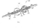
- FIG. 2 is a schematic diagram of a downhole tool having multiple pads, in accordance with an embodiment
- FIG. 3 is a cross-sectional view of a pad, in accordance with an embodiment
- FIG. 4 is a perspective view of a pad having a fastened pad cover, in accordance with an embodiment.
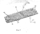
- FIG. 5 is a view of a pad and cover having a fastener to allow relative movement, in accordance with an embodiment.
- FIG. 1 shows a downhole system 10 cable head 11 connected at its lower end to a logging tool 12.
- An upper end of the cable head 11 is secured to a cable 14 in this embodiment.
- the cable 14 may be, for example, a wireline cable extending to the surface 16 of a well or hole 18 and is operable to lower the cable head 11 and one or more logging tools, such as logging tool 12, down to an area where formations and parameters are determined and recorded during logging operations.
- a vertical well 18 is shown but it should be understood that it can be highly deviated or even horizontal in another example.
- data may be transmitted from the logging tool 12 to the cable 14 through the cable head 11. Within the cable 14, the data may be transmitted to a data-transmission and acquisition system 20 at the surface 16.
- the downhole system 10 in the present application may include drilling or logging systems, such as measurement-while-drilling (MWD) systems, logging-while-drilling (LWD) systems, wireline systems, coiled tubing systems, testing systems, completions systems, productions systems, or combinations thereof.
- the logging tool 12 discussed herein may include any tool suitable for use in the downhole system 10.
- the logging tool 12 may be a downhole imaging tool suitable obtaining an image of formation surrounding the well 18.
- a downhole imaging tool may be suitable for obtaining resistivity or micro-resistivity measurements.
- the downhole imaging tool may measure the resistivity of the formation by injecting a current into the surrounding formation using an injection electrode.
- the current may return to the tool from the geological formation via a return electrode.
- the injection electrode may represent a current-measuring electrode through which this current may be measured.
- the impedance, or resistivity, of the surrounding formation may be determined.
- the measured resistivity and/or impedance may be used to obtain an image of the formation surrounding the well 18.
- the body of the downhole tool 12 may have one or more extendable arms carrying sensor pads.
- the arm or arms may be extended until the pad is placed against the wall of the borehole, at which point measurements are made using the sensors on the pad.
- multiple arms may extend multiple pads against a portion of the circumference of a borehole. The tool may be moved along the borehole such that the pad is disposed across the borehole wall and makes multiple measurements along the length of the borehole.
- FIG. 2 is a schematic configuration of a downhole tool having one or more extendable arms, according to embodiments of the invention.
- the downhole tool 12a may have one or more sets of arms 22a, 22b, 22c, 22d (four arms in each set) located spaced apart in the axial direction on the downhole tool 12a.
- Each arm is provided with a connection for a measurement pad 24.
- a centraliser or standoff 28 may be positioned at the bottom of the downhole tool 12a.
- each of the pads 24 may include functional electronic components for acquiring, processing, and transmitting measurements associated with the downhole formation. Such components may be arranged on a pad base and protected by a pad cover.
- FIG. 3 is a cross-sectional view of an example of a pad 24a including electronic components 30 for acquiring, processing, and or transmitting formation measurements disposed on a pad base 32.
- the electronic components 30 may be covered with a pad cover 34, and the pad base 32 and pad cover 34 may be substantially sealed to protect the electronic components 30 of the pad 24a.
- a bore sealing 36 may be used to seal the pad cover 34 to the pad base 32.
- sealing techniques may also be used to seal the pad cover or pad base to any of the electronic components 30.
- the bore sealing 38 may seal the pad cover 34 to button electrodes 40.
- FIG. 4 is a perspective view of a pad 24b having a pad cover 34 sealed on the pad base 32.
- the pad base 32 may have raised inserts 42, and the pad cover 34 may have depressions configured to fit the inserts 42 to seal the pad cover 34 to the pad base 32.
- the pad cover 34 may have raised inserts, and the pad base 32 may have depressions configured to fit the cover inserts.
- the inserts 42 may mechanically connect the pad base 32 and pad cover 34 in the XY plane (e.g., in the plane substantially along the plane of the pad base 32 and pad cover 34)
- the different electronic components 30, pad base 32, and pad cover 34 may include various different materials.
- the pad base 32 may have a substantially rigid metallic body while the pad base 34 may include a suitable high-temperature polymer (e.g., PEEK TM ).
- PEEK TM high-temperature polymer
- the various materials in the pad 24a may react differently due to the environmental conditions, as different materials may have different properties, such as thermal expansion.
- the pad base 32 and pad cover 34 may have move, shift, and/or expand relative to one another. Such relative movements between the pad base 32 and pad cover 34 may affect the sealing of the pad base 32 and pad cover 34.
- Embodiments of the present disclosure include techniques for reducing negative effects from the relative movements between a pad cover and pad base in a pad of a downhole tool.
- sliders may be implemented between a pad base 32 and a pad cover 34, such that relative movements in the x-axis and y-axis may be guided along a dimension of the slider, thereby reducing stress, shear, pressure, and/or deformation in the pad base 32, pad cover 34, and/or the sealing (e.g., sealing 36 and 38) in the pad 24.
- the illustration in FIG. 5 provides an example of a pad 24c having a pad base 32 and a pad cover 34 sealing electronic components of the pad 24c, including button electrodes 40.
- the pad cover 34 is faded in this illustration to depict the position of one embodiment of the sliders 44.
- the position of the sliders 44 may guide relative movements in the x- and y-directions (referred to as the XY plane; axis provided) of the pad base 32 and the pad cover 34, such that stress, sheer, pressure, and/or deformation which may result from such relative movement may be reduced.
- the sliders 44 may be positioned substantially parallel to one or more edges of the pad base 32 and pad cover 34.
- the sliders 44 may substantially surround in the XY plane one or more of the inserts 42 connecting the pad base 32 and pad cover 34.
- the shape, dimension, and size of the sliders 44 may be suitable for guiding relative movements between the pad cover 34 and the pad base 32.
- the guiding of relative movements may reduce effects, such as stress, sheering, or any force which may result in deformation or damage to the pad base 32, the pad cover 34, and/or electronic components 30 of the pad 24.
- the sliders 44 may be configured on the pad base 32, on the pad cover 34, independently from the pad base 32 and the pad cover 34, or in combinations of these implementations.
- the sliders may include a material suitable for high temperature and suitable for withstanding the relative movement between the pad base 32 and pad cover 34.
Landscapes
- Physics & Mathematics (AREA)
- Life Sciences & Earth Sciences (AREA)
- Engineering & Computer Science (AREA)
- Geology (AREA)
- Mining & Mineral Resources (AREA)
- Geophysics (AREA)
- Environmental & Geological Engineering (AREA)
- Fluid Mechanics (AREA)
- General Life Sciences & Earth Sciences (AREA)
- Geochemistry & Mineralogy (AREA)
- Gyroscopes (AREA)
- Connector Housings Or Holding Contact Members (AREA)
Abstract
Description
- This disclosure relates generally to downhole tools and more specifically to sealing techniques for the pad of a downhole tool.
- This section is intended to introduce the reader to various aspects of art that may be related to various aspects of the present techniques, which are described and/or claimed below. This discussion is believed to be helpful in providing the reader with background information to facilitate a better understanding of the various aspects of the present disclosure. Accordingly, it should be understood that these statements are to be read in this light, and not as admissions.
- Many downhole tools have been developed to determine properties of geological formations surrounding wells. One such downhole tool is referred to as a resistivity tool. Resistivity tools may inject a current into the surrounding geological formation using an injection electrode. The current may return to the tool from the geological formation via a return electrode. In general, the injection electrode may represent a current-measuring electrode (referred to as a measuring electrode) through which this current may be measured. By measuring the current, resistivity tools may determine the impedance, or resistivity, of the surrounding formation. For example, resistivity measurements may be used to obtain an image of the geological formation in the well.
- Downhole tools often include electronics, sensors, or other components that may be susceptible to the high ambient temperatures of the downhole environment. Such components are designed to operate within a certain range of temperatures, and these acceptable temperatures may be lower than the temperature in the borehole. In such contexts, maintaining the temperature sensitive components within the acceptable temperature range may prevent heat-related failures. Various techniques may be implemented to provide protection to such temperature sensitive components. For example, electronics, sensors, and other components may be covered, for example by a pad cover, to protect the components from the downhole environment.
-
FIG. 1 is a schematic diagram of a downhole system in accordance with an embodiment; -
FIG. 2 is a schematic diagram of a downhole tool having multiple pads, in accordance with an embodiment; -
FIG. 3 is a cross-sectional view of a pad, in accordance with an embodiment; -
FIG. 4 is a perspective view of a pad having a fastened pad cover, in accordance with an embodiment; and -
FIG. 5 is a view of a pad and cover having a fastener to allow relative movement, in accordance with an embodiment. - One or more specific embodiments of the present disclosure will be described below. These described embodiments are examples of the presently disclosed techniques. Additionally, in an effort to provide a concise description of these embodiments, certain features of an actual implementation may not be described in the specification. It should be appreciated that in the development of any such actual implementation, as in any engineering or design project, numerous implementation-specific decisions may be made to achieve the developers' specific goals, such as compliance with system-related and business-related constraints, which may vary from one implementation to another. Moreover, it may be appreciated that such a development effort might be complex and time consuming, but would nevertheless be a routine undertaking of design, fabrication, and manufacture for those of ordinary skill having the benefit of this disclosure.
- When introducing elements of various embodiments of the present disclosure, the articles "a," "an," and "the" are intended to mean that there are one or more of the elements. The terms "comprising," "including," and "having" are intended to be inclusive and mean that there may be additional elements other than the listed elements. Additionally, it should be understood that references to "one embodiment" or "an embodiment" of the present disclosure are not intended to be interpreted as excluding the existence of additional embodiments that also incorporate the recited features.
-
FIG. 1 shows adownhole system 10 cable head 11 connected at its lower end to alogging tool 12. An upper end of the cable head 11 is secured to acable 14 in this embodiment. Thecable 14 may be, for example, a wireline cable extending to thesurface 16 of a well orhole 18 and is operable to lower the cable head 11 and one or more logging tools, such aslogging tool 12, down to an area where formations and parameters are determined and recorded during logging operations. Avertical well 18 is shown but it should be understood that it can be highly deviated or even horizontal in another example. During a logging operation, data may be transmitted from thelogging tool 12 to thecable 14 through the cable head 11. Within thecable 14, the data may be transmitted to a data-transmission andacquisition system 20 at thesurface 16. - While a wireline cable is provided as an example of one implementation of the
cable 14, thedownhole system 10 in the present application may include drilling or logging systems, such as measurement-while-drilling (MWD) systems, logging-while-drilling (LWD) systems, wireline systems, coiled tubing systems, testing systems, completions systems, productions systems, or combinations thereof. Furthermore, thelogging tool 12 discussed herein may include any tool suitable for use in thedownhole system 10. - In some embodiments, the
logging tool 12 may be a downhole imaging tool suitable obtaining an image of formation surrounding thewell 18. For example, a downhole imaging tool may be suitable for obtaining resistivity or micro-resistivity measurements. The downhole imaging tool may measure the resistivity of the formation by injecting a current into the surrounding formation using an injection electrode. The current may return to the tool from the geological formation via a return electrode. In general, the injection electrode may represent a current-measuring electrode through which this current may be measured. By measuring the current, the impedance, or resistivity, of the surrounding formation may be determined. The measured resistivity and/or impedance may be used to obtain an image of the formation surrounding thewell 18. - In one embodiment, the body of the
downhole tool 12 may have one or more extendable arms carrying sensor pads. In use, the arm or arms may be extended until the pad is placed against the wall of the borehole, at which point measurements are made using the sensors on the pad. In some embodiments, multiple arms may extend multiple pads against a portion of the circumference of a borehole. The tool may be moved along the borehole such that the pad is disposed across the borehole wall and makes multiple measurements along the length of the borehole. - For example,
FIG. 2 is a schematic configuration of a downhole tool having one or more extendable arms, according to embodiments of the invention. The downhole tool 12a may have one or more sets ofarms measurement pad 24. In one embodiment, a centraliser orstandoff 28 may be positioned at the bottom of the downhole tool 12a. - As the pads may operate in relatively high temperature and high pressure environments, electronic components in the
pads 24 may be configured to perform reliably in such an environment. In some embodiments, each of thepads 24 may include functional electronic components for acquiring, processing, and transmitting measurements associated with the downhole formation. Such components may be arranged on a pad base and protected by a pad cover. -
FIG. 3 is a cross-sectional view of an example of apad 24a includingelectronic components 30 for acquiring, processing, and or transmitting formation measurements disposed on apad base 32. Theelectronic components 30 may be covered with apad cover 34, and thepad base 32 andpad cover 34 may be substantially sealed to protect theelectronic components 30 of thepad 24a. For example, a bore sealing 36 may be used to seal thepad cover 34 to thepad base 32. Furthermore, sealing techniques may also be used to seal the pad cover or pad base to any of theelectronic components 30. For example, the bore sealing 38 may seal thepad cover 34 tobutton electrodes 40. -
FIG. 4 is a perspective view of a pad 24b having apad cover 34 sealed on thepad base 32. As illustrated inFIG. 4 , thepad base 32 may have raisedinserts 42, and thepad cover 34 may have depressions configured to fit theinserts 42 to seal thepad cover 34 to thepad base 32. In some embodiments, thepad cover 34 may have raised inserts, and thepad base 32 may have depressions configured to fit the cover inserts. In some embodiments, theinserts 42 may mechanically connect thepad base 32 and pad cover 34 in the XY plane (e.g., in the plane substantially along the plane of thepad base 32 and pad cover 34) - The different
electronic components 30,pad base 32, and pad cover 34 may include various different materials. For example, due to the environmental conditions which thepad 24a may be exposed to, thepad base 32 may have a substantially rigid metallic body while thepad base 34 may include a suitable high-temperature polymer (e.g., PEEK™). The various materials in thepad 24a may react differently due to the environmental conditions, as different materials may have different properties, such as thermal expansion. Furthermore, due to operations of thepad 24a downhole, thepad base 32 and pad cover 34 may have move, shift, and/or expand relative to one another. Such relative movements between thepad base 32 and pad cover 34 may affect the sealing of thepad base 32 andpad cover 34. - Embodiments of the present disclosure include techniques for reducing negative effects from the relative movements between a pad cover and pad base in a pad of a downhole tool. In one embodiment, sliders may be implemented between a
pad base 32 and apad cover 34, such that relative movements in the x-axis and y-axis may be guided along a dimension of the slider, thereby reducing stress, shear, pressure, and/or deformation in thepad base 32,pad cover 34, and/or the sealing (e.g., sealing 36 and 38) in thepad 24. - The illustration in
FIG. 5 provides an example of apad 24c having apad base 32 and apad cover 34 sealing electronic components of thepad 24c, includingbutton electrodes 40. Thepad cover 34 is faded in this illustration to depict the position of one embodiment of thesliders 44. The position of thesliders 44 may guide relative movements in the x- and y-directions (referred to as the XY plane; axis provided) of thepad base 32 and thepad cover 34, such that stress, sheer, pressure, and/or deformation which may result from such relative movement may be reduced. For example, thesliders 44 may be positioned substantially parallel to one or more edges of thepad base 32 andpad cover 34. In some embodiments, thesliders 44 may substantially surround in the XY plane one or more of theinserts 42 connecting thepad base 32 andpad cover 34. - In some embodiments, the shape, dimension, and size of the
sliders 44 may be suitable for guiding relative movements between thepad cover 34 and thepad base 32. The guiding of relative movements may reduce effects, such as stress, sheering, or any force which may result in deformation or damage to thepad base 32, thepad cover 34, and/orelectronic components 30 of thepad 24. - In different embodiments, the
sliders 44 may be configured on thepad base 32, on thepad cover 34, independently from thepad base 32 and thepad cover 34, or in combinations of these implementations. In one or more embodiments, the sliders may include a material suitable for high temperature and suitable for withstanding the relative movement between thepad base 32 andpad cover 34. - Various refinements of the features noted above may exist in relation to various aspects of this disclosure. Further features may also be incorporated in these various aspects as well. These refinements and additional features may exist individually or in any combination. For instance, various features discussed below in relation to one or more of the illustrated embodiments may be incorporated into any of the above-described aspects of this disclosure alone or in any combination. The brief summary presented above is intended to familiarize the reader with certain aspects and contexts of embodiments of this disclosure without limitation to the claimed subject matter.
Claims (14)
- A downhole tool comprising:one or more pads, wherein each of the one or more pads comprises:a pad base;electronic components disposed on the pad base;a pad cover sealed to the pad base, substantially encompassing the electronic components; andone or more sliders positioned between the pad base and the pad cover.
- The downhole tool of claim 1, wherein the one or more sliders are configured to guide relative movements between the pad base and the pad cover.
- The downhole tool of claim 1, wherein the one or more sliders are configured to guide movements of the pad base and the pad cover along an XY plane.
- The downhole tool of claim 1, comprising one or more inserts between the pad base and the pad cover, wherein the inserts mechanically couple the pad base and pad cover in an XY plane.
- The downhole tool of claim 4, wherein the one or more sliders substantially surround one or more of the one or more inserts in the XY plane.
- The downhole tool of claim 1, wherein the one or more sliders are disposed substantially parallel to one or more edges of the pad base and the pad cover.
- The downhole tool of claim 1, wherein the pad cover comprises a polymer suitable for maintaining properties in high temperatures.
- The downhole tool of claim 7, wherein the pad cover comprises PEEK™.
- The downhole tool of claim 1, wherein the one or more sliders comprises a polymer suitable for maintaining properties in high temperatures.
- The downhole tool of claim 9, wherein the one or more sliders comprises PEEK™ .
- The downhole tool of claim 1, wherein the one or more of the one or more sliders comprise different materials or combinations of materials from others of the one or more sliders.
- The downhole tool of claim 1, wherein the one or more sliders are shaped to be suitable for guiding relative movements between the pad base and the pad cover.
- The downhole tool of claim 1, wherein the one or more sliders are configured to reduce force on the pad base, the pad cover, the electronic components, or combinations thereof.
- The downhole tool of claim 1, wherein the one or more sliders are configured to reduce effects of relative movement between the pad base and the pad cover.
Priority Applications (3)
| Application Number | Priority Date | Filing Date | Title |
|---|---|---|---|
| EP13305036.9A EP2754853B1 (en) | 2013-01-15 | 2013-01-15 | Fastening technique in a downhole tool |
| US14/761,289 US20150361781A1 (en) | 2013-01-15 | 2014-01-15 | Fastening Technique in a Downhole Tool |
| PCT/US2014/011565 WO2014113410A1 (en) | 2013-01-15 | 2014-01-15 | Fastening technique in a downhole tool |
Applications Claiming Priority (1)
| Application Number | Priority Date | Filing Date | Title |
|---|---|---|---|
| EP13305036.9A EP2754853B1 (en) | 2013-01-15 | 2013-01-15 | Fastening technique in a downhole tool |
Publications (2)
| Publication Number | Publication Date |
|---|---|
| EP2754853A1 true EP2754853A1 (en) | 2014-07-16 |
| EP2754853B1 EP2754853B1 (en) | 2016-12-28 |
Family
ID=47683667
Family Applications (1)
| Application Number | Title | Priority Date | Filing Date |
|---|---|---|---|
| EP13305036.9A Not-in-force EP2754853B1 (en) | 2013-01-15 | 2013-01-15 | Fastening technique in a downhole tool |
Country Status (3)
| Country | Link |
|---|---|
| US (1) | US20150361781A1 (en) |
| EP (1) | EP2754853B1 (en) |
| WO (1) | WO2014113410A1 (en) |
Cited By (1)
| Publication number | Priority date | Publication date | Assignee | Title |
|---|---|---|---|---|
| US11359489B2 (en) | 2017-12-22 | 2022-06-14 | Halliburton Energy Services, Inc. | Formation tester tool having an extendable probe and a sealing pad with a movable shield |
Families Citing this family (2)
| Publication number | Priority date | Publication date | Assignee | Title |
|---|---|---|---|---|
| CN106321091B (en) * | 2016-08-29 | 2020-06-09 | 中国石油天然气集团公司 | High-temperature ultrahigh-pressure micro-resistivity scanning imaging polar plate and preparation method thereof |
| CN110486006B (en) * | 2019-08-21 | 2022-06-14 | 中国海洋石油集团有限公司 | Resistivity measurement polar plate and manufacturing method thereof |
Citations (6)
| Publication number | Priority date | Publication date | Assignee | Title |
|---|---|---|---|---|
| US2695820A (en) * | 1953-02-17 | 1954-11-30 | Schlumberger Well Surv Corp | Carrier pad for use in boreholes |
| GB728565A (en) * | 1952-06-27 | 1955-04-20 | Schlumberger Well Surv Corp | Improvements in or relating to electrode carrier device for electrical well logging apparatus |
| US3017566A (en) * | 1959-06-16 | 1962-01-16 | Schlumberger Well Surv Corp | Apparatus for investigating earth formations |
| US3818324A (en) * | 1971-04-19 | 1974-06-18 | Schlumberger Technology Corp | Well logging pad having a flexible electrode structure |
| US20070103162A1 (en) * | 2005-11-04 | 2007-05-10 | Halliburton Energy Services, Inc. | Oil Based Mud Imaging Tool With Common Mode Voltage Compensation |
| US20070181298A1 (en) * | 2006-02-09 | 2007-08-09 | Sheiretov Todor K | Self-anchoring device with force amplification |
-
2013
- 2013-01-15 EP EP13305036.9A patent/EP2754853B1/en not_active Not-in-force
-
2014
- 2014-01-15 US US14/761,289 patent/US20150361781A1/en not_active Abandoned
- 2014-01-15 WO PCT/US2014/011565 patent/WO2014113410A1/en not_active Ceased
Patent Citations (6)
| Publication number | Priority date | Publication date | Assignee | Title |
|---|---|---|---|---|
| GB728565A (en) * | 1952-06-27 | 1955-04-20 | Schlumberger Well Surv Corp | Improvements in or relating to electrode carrier device for electrical well logging apparatus |
| US2695820A (en) * | 1953-02-17 | 1954-11-30 | Schlumberger Well Surv Corp | Carrier pad for use in boreholes |
| US3017566A (en) * | 1959-06-16 | 1962-01-16 | Schlumberger Well Surv Corp | Apparatus for investigating earth formations |
| US3818324A (en) * | 1971-04-19 | 1974-06-18 | Schlumberger Technology Corp | Well logging pad having a flexible electrode structure |
| US20070103162A1 (en) * | 2005-11-04 | 2007-05-10 | Halliburton Energy Services, Inc. | Oil Based Mud Imaging Tool With Common Mode Voltage Compensation |
| US20070181298A1 (en) * | 2006-02-09 | 2007-08-09 | Sheiretov Todor K | Self-anchoring device with force amplification |
Cited By (1)
| Publication number | Priority date | Publication date | Assignee | Title |
|---|---|---|---|---|
| US11359489B2 (en) | 2017-12-22 | 2022-06-14 | Halliburton Energy Services, Inc. | Formation tester tool having an extendable probe and a sealing pad with a movable shield |
Also Published As
| Publication number | Publication date |
|---|---|
| EP2754853B1 (en) | 2016-12-28 |
| US20150361781A1 (en) | 2015-12-17 |
| WO2014113410A1 (en) | 2014-07-24 |
Similar Documents
| Publication | Publication Date | Title |
|---|---|---|
| US8943884B2 (en) | Smart seals and other elastomer systems for health and pressure monitoring | |
| US7545145B2 (en) | Method and apparatus for tensorial micro-resistivity imaging in oil-based muds | |
| US12473820B2 (en) | Indirect detection of bending of a collar | |
| US11739629B2 (en) | Strain gauges for detecting deformations of a plate | |
| EP2754853B1 (en) | Fastening technique in a downhole tool | |
| GB2437824A (en) | Logging tool with sleeve | |
| US20080303525A1 (en) | Single-dipole high frequency electric imager | |
| CA2534600A1 (en) | Method for locating casing joints using measurement while drilling tool | |
| US8237446B2 (en) | High resolution resistivity earth imager | |
| US9611723B2 (en) | Heat transferring electronics chassis | |
| US20170145806A1 (en) | Borehole Wall Imaging Tool Having A Grooved Wall-Contacting Face | |
| US10519762B2 (en) | Lateral support for downhole electronics | |
| AU2015378541B2 (en) | Downhole electrode apparatus, systems, and methods | |
| US10865632B2 (en) | Downhole tension sensing apparatus | |
| US8925378B2 (en) | Modular apparatus and method for making measurements in boreholes | |
| US10246986B2 (en) | Magnetometer mounting for isolation and interference reduction | |
| US10386525B2 (en) | Uniaxial anisotropy detection apparatus, systems, and methods | |
| EP2755062A1 (en) | Asic concept for a downhole tool | |
| CN205743883U (en) | A kind of high temperature resistant continuous direct-reading gyro well logging apparatus | |
| EP2755061A1 (en) | Digitizing in a pad of a downhole tool exposed to hydrostatic pressure | |
| Bammi et al. | A new slim full bore electrical micro-imaging tool conveyed through the drill string and bit for geological and reservoir characterization of unconventional reservoirs | |
| US10502857B2 (en) | Device for measuring resistivity in a wellbore | |
| US20150354338A1 (en) | Downhole Apparatus with Extendable Digitized Sensor Device | |
| WO2023048739A1 (en) | Velocity correction with joint inversion |
Legal Events
| Date | Code | Title | Description |
|---|---|---|---|
| PUAI | Public reference made under article 153(3) epc to a published international application that has entered the european phase |
Free format text: ORIGINAL CODE: 0009012 |
|
| 17P | Request for examination filed |
Effective date: 20130115 |
|
| AK | Designated contracting states |
Kind code of ref document: A1 Designated state(s): AL AT BE BG CH CY CZ DE DK EE ES FI FR GB GR HR HU IE IS IT LI LT LU LV MC MK MT NL NO PL PT RO RS SE SI SK SM TR |
|
| AX | Request for extension of the european patent |
Extension state: BA ME |
|
| R17P | Request for examination filed (corrected) |
Effective date: 20150115 |
|
| RBV | Designated contracting states (corrected) |
Designated state(s): AL AT BE BG CH CY CZ DE DK EE ES FI FR GB GR HR HU IE IS IT LI LT LU LV MC MK MT NL NO PL PT RO RS SE SI SK SM TR |
|
| GRAP | Despatch of communication of intention to grant a patent |
Free format text: ORIGINAL CODE: EPIDOSNIGR1 |
|
| INTG | Intention to grant announced |
Effective date: 20160928 |
|
| GRAS | Grant fee paid |
Free format text: ORIGINAL CODE: EPIDOSNIGR3 |
|
| GRAA | (expected) grant |
Free format text: ORIGINAL CODE: 0009210 |
|
| AK | Designated contracting states |
Kind code of ref document: B1 Designated state(s): AL AT BE BG CH CY CZ DE DK EE ES FI FR GB GR HR HU IE IS IT LI LT LU LV MC MK MT NL NO PL PT RO RS SE SI SK SM TR |
|
| REG | Reference to a national code |
Ref country code: GB Ref legal event code: FG4D |
|
| REG | Reference to a national code |
Ref country code: CH Ref legal event code: EP |
|
| REG | Reference to a national code |
Ref country code: AT Ref legal event code: REF Ref document number: 857478 Country of ref document: AT Kind code of ref document: T Effective date: 20170115 |
|
| REG | Reference to a national code |
Ref country code: IE Ref legal event code: FG4D |
|
| REG | Reference to a national code |
Ref country code: DE Ref legal event code: R096 Ref document number: 602013015826 Country of ref document: DE |
|
| PG25 | Lapsed in a contracting state [announced via postgrant information from national office to epo] |
Ref country code: LV Free format text: LAPSE BECAUSE OF FAILURE TO SUBMIT A TRANSLATION OF THE DESCRIPTION OR TO PAY THE FEE WITHIN THE PRESCRIBED TIME-LIMIT Effective date: 20161228 |
|
| REG | Reference to a national code |
Ref country code: LT Ref legal event code: MG4D |
|
| PG25 | Lapsed in a contracting state [announced via postgrant information from national office to epo] |
Ref country code: LT Free format text: LAPSE BECAUSE OF FAILURE TO SUBMIT A TRANSLATION OF THE DESCRIPTION OR TO PAY THE FEE WITHIN THE PRESCRIBED TIME-LIMIT Effective date: 20161228 Ref country code: NO Free format text: LAPSE BECAUSE OF FAILURE TO SUBMIT A TRANSLATION OF THE DESCRIPTION OR TO PAY THE FEE WITHIN THE PRESCRIBED TIME-LIMIT Effective date: 20170328 Ref country code: GR Free format text: LAPSE BECAUSE OF FAILURE TO SUBMIT A TRANSLATION OF THE DESCRIPTION OR TO PAY THE FEE WITHIN THE PRESCRIBED TIME-LIMIT Effective date: 20170329 Ref country code: SE Free format text: LAPSE BECAUSE OF FAILURE TO SUBMIT A TRANSLATION OF THE DESCRIPTION OR TO PAY THE FEE WITHIN THE PRESCRIBED TIME-LIMIT Effective date: 20161228 |
|
| REG | Reference to a national code |
Ref country code: NL Ref legal event code: MP Effective date: 20161228 |
|
| REG | Reference to a national code |
Ref country code: AT Ref legal event code: MK05 Ref document number: 857478 Country of ref document: AT Kind code of ref document: T Effective date: 20161228 |
|
| PG25 | Lapsed in a contracting state [announced via postgrant information from national office to epo] |
Ref country code: RS Free format text: LAPSE BECAUSE OF FAILURE TO SUBMIT A TRANSLATION OF THE DESCRIPTION OR TO PAY THE FEE WITHIN THE PRESCRIBED TIME-LIMIT Effective date: 20161228 Ref country code: HR Free format text: LAPSE BECAUSE OF FAILURE TO SUBMIT A TRANSLATION OF THE DESCRIPTION OR TO PAY THE FEE WITHIN THE PRESCRIBED TIME-LIMIT Effective date: 20161228 Ref country code: FI Free format text: LAPSE BECAUSE OF FAILURE TO SUBMIT A TRANSLATION OF THE DESCRIPTION OR TO PAY THE FEE WITHIN THE PRESCRIBED TIME-LIMIT Effective date: 20161228 Ref country code: BE Free format text: LAPSE BECAUSE OF NON-PAYMENT OF DUE FEES Effective date: 20170131 |
|
| PG25 | Lapsed in a contracting state [announced via postgrant information from national office to epo] |
Ref country code: NL Free format text: LAPSE BECAUSE OF FAILURE TO SUBMIT A TRANSLATION OF THE DESCRIPTION OR TO PAY THE FEE WITHIN THE PRESCRIBED TIME-LIMIT Effective date: 20161228 |
|
| PG25 | Lapsed in a contracting state [announced via postgrant information from national office to epo] |
Ref country code: CZ Free format text: LAPSE BECAUSE OF FAILURE TO SUBMIT A TRANSLATION OF THE DESCRIPTION OR TO PAY THE FEE WITHIN THE PRESCRIBED TIME-LIMIT Effective date: 20161228 Ref country code: IS Free format text: LAPSE BECAUSE OF FAILURE TO SUBMIT A TRANSLATION OF THE DESCRIPTION OR TO PAY THE FEE WITHIN THE PRESCRIBED TIME-LIMIT Effective date: 20170428 Ref country code: RO Free format text: LAPSE BECAUSE OF FAILURE TO SUBMIT A TRANSLATION OF THE DESCRIPTION OR TO PAY THE FEE WITHIN THE PRESCRIBED TIME-LIMIT Effective date: 20161228 Ref country code: SK Free format text: LAPSE BECAUSE OF FAILURE TO SUBMIT A TRANSLATION OF THE DESCRIPTION OR TO PAY THE FEE WITHIN THE PRESCRIBED TIME-LIMIT Effective date: 20161228 Ref country code: EE Free format text: LAPSE BECAUSE OF FAILURE TO SUBMIT A TRANSLATION OF THE DESCRIPTION OR TO PAY THE FEE WITHIN THE PRESCRIBED TIME-LIMIT Effective date: 20161228 |
|
| REG | Reference to a national code |
Ref country code: DE Ref legal event code: R119 Ref document number: 602013015826 Country of ref document: DE |
|
| PG25 | Lapsed in a contracting state [announced via postgrant information from national office to epo] |
Ref country code: PT Free format text: LAPSE BECAUSE OF FAILURE TO SUBMIT A TRANSLATION OF THE DESCRIPTION OR TO PAY THE FEE WITHIN THE PRESCRIBED TIME-LIMIT Effective date: 20170428 Ref country code: BE Free format text: LAPSE BECAUSE OF FAILURE TO SUBMIT A TRANSLATION OF THE DESCRIPTION OR TO PAY THE FEE WITHIN THE PRESCRIBED TIME-LIMIT Effective date: 20161228 Ref country code: BG Free format text: LAPSE BECAUSE OF FAILURE TO SUBMIT A TRANSLATION OF THE DESCRIPTION OR TO PAY THE FEE WITHIN THE PRESCRIBED TIME-LIMIT Effective date: 20170328 Ref country code: SM Free format text: LAPSE BECAUSE OF FAILURE TO SUBMIT A TRANSLATION OF THE DESCRIPTION OR TO PAY THE FEE WITHIN THE PRESCRIBED TIME-LIMIT Effective date: 20161228 Ref country code: PL Free format text: LAPSE BECAUSE OF FAILURE TO SUBMIT A TRANSLATION OF THE DESCRIPTION OR TO PAY THE FEE WITHIN THE PRESCRIBED TIME-LIMIT Effective date: 20161228 Ref country code: IT Free format text: LAPSE BECAUSE OF FAILURE TO SUBMIT A TRANSLATION OF THE DESCRIPTION OR TO PAY THE FEE WITHIN THE PRESCRIBED TIME-LIMIT Effective date: 20161228 Ref country code: AT Free format text: LAPSE BECAUSE OF FAILURE TO SUBMIT A TRANSLATION OF THE DESCRIPTION OR TO PAY THE FEE WITHIN THE PRESCRIBED TIME-LIMIT Effective date: 20161228 Ref country code: ES Free format text: LAPSE BECAUSE OF FAILURE TO SUBMIT A TRANSLATION OF THE DESCRIPTION OR TO PAY THE FEE WITHIN THE PRESCRIBED TIME-LIMIT Effective date: 20161228 |
|
| REG | Reference to a national code |
Ref country code: CH Ref legal event code: PL |
|
| PG25 | Lapsed in a contracting state [announced via postgrant information from national office to epo] |
Ref country code: MC Free format text: LAPSE BECAUSE OF FAILURE TO SUBMIT A TRANSLATION OF THE DESCRIPTION OR TO PAY THE FEE WITHIN THE PRESCRIBED TIME-LIMIT Effective date: 20161228 |
|
| PG25 | Lapsed in a contracting state [announced via postgrant information from national office to epo] |
Ref country code: CH Free format text: LAPSE BECAUSE OF NON-PAYMENT OF DUE FEES Effective date: 20170131 Ref country code: LI Free format text: LAPSE BECAUSE OF NON-PAYMENT OF DUE FEES Effective date: 20170131 |
|
| REG | Reference to a national code |
Ref country code: IE Ref legal event code: MM4A |
|
| PLBE | No opposition filed within time limit |
Free format text: ORIGINAL CODE: 0009261 |
|
| STAA | Information on the status of an ep patent application or granted ep patent |
Free format text: STATUS: NO OPPOSITION FILED WITHIN TIME LIMIT |
|
| PG25 | Lapsed in a contracting state [announced via postgrant information from national office to epo] |
Ref country code: DK Free format text: LAPSE BECAUSE OF FAILURE TO SUBMIT A TRANSLATION OF THE DESCRIPTION OR TO PAY THE FEE WITHIN THE PRESCRIBED TIME-LIMIT Effective date: 20161228 Ref country code: LU Free format text: LAPSE BECAUSE OF NON-PAYMENT OF DUE FEES Effective date: 20170115 Ref country code: DE Free format text: LAPSE BECAUSE OF NON-PAYMENT OF DUE FEES Effective date: 20170801 |
|
| 26N | No opposition filed |
Effective date: 20170929 |
|
| REG | Reference to a national code |
Ref country code: FR Ref legal event code: ST Effective date: 20171115 |
|
| PG25 | Lapsed in a contracting state [announced via postgrant information from national office to epo] |
Ref country code: FR Free format text: LAPSE BECAUSE OF NON-PAYMENT OF DUE FEES Effective date: 20170228 |
|
| PG25 | Lapsed in a contracting state [announced via postgrant information from national office to epo] |
Ref country code: SI Free format text: LAPSE BECAUSE OF FAILURE TO SUBMIT A TRANSLATION OF THE DESCRIPTION OR TO PAY THE FEE WITHIN THE PRESCRIBED TIME-LIMIT Effective date: 20161228 Ref country code: IE Free format text: LAPSE BECAUSE OF NON-PAYMENT OF DUE FEES Effective date: 20170115 |
|
| PG25 | Lapsed in a contracting state [announced via postgrant information from national office to epo] |
Ref country code: MT Free format text: LAPSE BECAUSE OF NON-PAYMENT OF DUE FEES Effective date: 20170115 |
|
| PG25 | Lapsed in a contracting state [announced via postgrant information from national office to epo] |
Ref country code: HU Free format text: LAPSE BECAUSE OF FAILURE TO SUBMIT A TRANSLATION OF THE DESCRIPTION OR TO PAY THE FEE WITHIN THE PRESCRIBED TIME-LIMIT; INVALID AB INITIO Effective date: 20130115 |
|
| PG25 | Lapsed in a contracting state [announced via postgrant information from national office to epo] |
Ref country code: CY Free format text: LAPSE BECAUSE OF NON-PAYMENT OF DUE FEES Effective date: 20161228 |
|
| PG25 | Lapsed in a contracting state [announced via postgrant information from national office to epo] |
Ref country code: MK Free format text: LAPSE BECAUSE OF FAILURE TO SUBMIT A TRANSLATION OF THE DESCRIPTION OR TO PAY THE FEE WITHIN THE PRESCRIBED TIME-LIMIT Effective date: 20161228 |
|
| PG25 | Lapsed in a contracting state [announced via postgrant information from national office to epo] |
Ref country code: TR Free format text: LAPSE BECAUSE OF FAILURE TO SUBMIT A TRANSLATION OF THE DESCRIPTION OR TO PAY THE FEE WITHIN THE PRESCRIBED TIME-LIMIT Effective date: 20161228 |
|
| PG25 | Lapsed in a contracting state [announced via postgrant information from national office to epo] |
Ref country code: AL Free format text: LAPSE BECAUSE OF FAILURE TO SUBMIT A TRANSLATION OF THE DESCRIPTION OR TO PAY THE FEE WITHIN THE PRESCRIBED TIME-LIMIT Effective date: 20161228 |
|
| PGFP | Annual fee paid to national office [announced via postgrant information from national office to epo] |
Ref country code: GB Payment date: 20231123 Year of fee payment: 12 |
|
| GBPC | Gb: european patent ceased through non-payment of renewal fee |
Effective date: 20250115 |
|
| PG25 | Lapsed in a contracting state [announced via postgrant information from national office to epo] |
Ref country code: GB Free format text: LAPSE BECAUSE OF NON-PAYMENT OF DUE FEES Effective date: 20250115 |