EP2754826A2 - Drive unit for a revolving door in a flat, disc-shaped form - Google Patents
Drive unit for a revolving door in a flat, disc-shaped form Download PDFInfo
- Publication number
- EP2754826A2 EP2754826A2 EP14000034.0A EP14000034A EP2754826A2 EP 2754826 A2 EP2754826 A2 EP 2754826A2 EP 14000034 A EP14000034 A EP 14000034A EP 2754826 A2 EP2754826 A2 EP 2754826A2
- Authority
- EP
- European Patent Office
- Prior art keywords
- drive unit
- rotor part
- stator
- turnstile
- revolving door
- Prior art date
- Legal status (The legal status is an assumption and is not a legal conclusion. Google has not performed a legal analysis and makes no representation as to the accuracy of the status listed.)
- Pending
Links
- 238000000034 method Methods 0.000 claims abstract description 8
- 230000005405 multipole Effects 0.000 claims abstract description 8
- 230000000284 resting effect Effects 0.000 claims description 6
- 238000004804 winding Methods 0.000 claims description 4
- 230000008901 benefit Effects 0.000 description 15
- 230000000903 blocking effect Effects 0.000 description 10
- 230000005540 biological transmission Effects 0.000 description 6
- 238000013461 design Methods 0.000 description 6
- 238000009434 installation Methods 0.000 description 4
- 238000011161 development Methods 0.000 description 2
- 230000018109 developmental process Effects 0.000 description 2
- 230000010354 integration Effects 0.000 description 2
- 230000009466 transformation Effects 0.000 description 2
- 230000004913 activation Effects 0.000 description 1
- 230000015572 biosynthetic process Effects 0.000 description 1
- 230000001419 dependent effect Effects 0.000 description 1
- 230000001771 impaired effect Effects 0.000 description 1
- 230000003993 interaction Effects 0.000 description 1
- 238000012986 modification Methods 0.000 description 1
- 230000004048 modification Effects 0.000 description 1
- 238000012544 monitoring process Methods 0.000 description 1
- 230000008092 positive effect Effects 0.000 description 1
- 238000012545 processing Methods 0.000 description 1
- 239000004065 semiconductor Substances 0.000 description 1
- 230000003068 static effect Effects 0.000 description 1
- 239000012780 transparent material Substances 0.000 description 1
Images


Classifications
-
- H—ELECTRICITY
- H02—GENERATION; CONVERSION OR DISTRIBUTION OF ELECTRIC POWER
- H02K—DYNAMO-ELECTRIC MACHINES
- H02K1/00—Details of the magnetic circuit
- H02K1/06—Details of the magnetic circuit characterised by the shape, form or construction
- H02K1/22—Rotating parts of the magnetic circuit
- H02K1/27—Rotor cores with permanent magnets
- H02K1/2786—Outer rotors
- H02K1/2787—Outer rotors the magnetisation axis of the magnets being perpendicular to the rotor axis
- H02K1/2789—Outer rotors the magnetisation axis of the magnets being perpendicular to the rotor axis the rotor consisting of two or more circumferentially positioned magnets
- H02K1/2791—Surface mounted magnets; Inset magnets
-
- E—FIXED CONSTRUCTIONS
- E05—LOCKS; KEYS; WINDOW OR DOOR FITTINGS; SAFES
- E05F—DEVICES FOR MOVING WINGS INTO OPEN OR CLOSED POSITION; CHECKS FOR WINGS; WING FITTINGS NOT OTHERWISE PROVIDED FOR, CONCERNED WITH THE FUNCTIONING OF THE WING
- E05F15/00—Power-operated mechanisms for wings
- E05F15/60—Power-operated mechanisms for wings using electrical actuators
- E05F15/603—Power-operated mechanisms for wings using electrical actuators using rotary electromotors
- E05F15/608—Power-operated mechanisms for wings using electrical actuators using rotary electromotors for revolving wings
-
- H—ELECTRICITY
- H02—GENERATION; CONVERSION OR DISTRIBUTION OF ELECTRIC POWER
- H02K—DYNAMO-ELECTRIC MACHINES
- H02K11/00—Structural association of dynamo-electric machines with electric components or with devices for shielding, monitoring or protection
- H02K11/30—Structural association with control circuits or drive circuits
-
- E—FIXED CONSTRUCTIONS
- E05—LOCKS; KEYS; WINDOW OR DOOR FITTINGS; SAFES
- E05D—HINGES OR SUSPENSION DEVICES FOR DOORS, WINDOWS OR WINGS
- E05D15/00—Suspension arrangements for wings
- E05D15/02—Suspension arrangements for wings for revolving wings
-
- E—FIXED CONSTRUCTIONS
- E05—LOCKS; KEYS; WINDOW OR DOOR FITTINGS; SAFES
- E05Y—INDEXING SCHEME RELATING TO HINGES OR OTHER SUSPENSION DEVICES FOR DOORS, WINDOWS OR WINGS AND DEVICES FOR MOVING WINGS INTO OPEN OR CLOSED POSITION, CHECKS FOR WINGS AND WING FITTINGS NOT OTHERWISE PROVIDED FOR, CONCERNED WITH THE FUNCTIONING OF THE WING
- E05Y2800/00—Details, accessories and auxiliary operations not otherwise provided for
- E05Y2800/10—Additional functions
- E05Y2800/106—Lighting
-
- E—FIXED CONSTRUCTIONS
- E05—LOCKS; KEYS; WINDOW OR DOOR FITTINGS; SAFES
- E05Y—INDEXING SCHEME RELATING TO HINGES OR OTHER SUSPENSION DEVICES FOR DOORS, WINDOWS OR WINGS AND DEVICES FOR MOVING WINGS INTO OPEN OR CLOSED POSITION, CHECKS FOR WINGS AND WING FITTINGS NOT OTHERWISE PROVIDED FOR, CONCERNED WITH THE FUNCTIONING OF THE WING
- E05Y2900/00—Application of doors, windows, wings or fittings thereof
- E05Y2900/10—Application of doors, windows, wings or fittings thereof for buildings or parts thereof
- E05Y2900/13—Application of doors, windows, wings or fittings thereof for buildings or parts thereof characterised by the type of wing
- E05Y2900/132—Doors
Definitions
- the present invention relates to a drive unit for a revolving door with an electronically commutated Dahlpolmotor, wherein the Dahlpolmotor has a number of coil elements and magnetic elements and has a flat basic structure. Furthermore, the invention is directed to the arrangement of such a drive unit on a revolving door and to a method for arranging the drive unit.
- the DE 10 2010 024 108 A1 shows a generic drive unit for a revolving door with an electronically commutated Dahlpolmotor, and the Dahlpolmotor is flat and has a round basic structure.
- the Dahlpolmotor has an axis of rotation, which coincides with the axis of rotation of the turnstile of the revolving door.
- a drive unit for a revolving door as electronically commutated Dahlpolmotor allows a particularly advantageous integration of the drive unit in the structure of the revolving door.
- the drive unit can be mounted on the bottom side, and it is not a large receiving space for receiving the drive unit in the shell of a building necessary.
- the flat design of the drive unit results in particular from the fact that the electronically commutated Dahlpolmotor can be connected directly to the turnstile of the revolving door, so that the drive unit does not have to have a transmission.
- Electronically commutated multi-pole motors however, have output shafts to which components to be driven, for example the turnstile of a revolving door, are arranged be transmitted to the rotational movement of the output shaft to the components.
- Newer revolving doors require drive units that must be very flat.
- the use of a transmission in conjunction with an output shaft already causes a significant increase in the height of the drive unit in the rotational axis of the turnstile, and especially in floor-mounted drive units, but also in ceiling-mounted drive units large heights often lead to constructive, but also to aesthetic disadvantages in the device the revolving door, for example, in the facade of a building.
- the object of the invention is to provide a drive unit for a revolving door, an arrangement of a drive unit in a revolving door and a revolving door with such a drive unit, which has a low overall height and is simple.
- the invention proposes a drive unit for a revolving door with an electronically commutated Dahlpolmotor with a number of coil elements and with a number of magnetic elements, wherein the Dahlpolmotor has a flat-shaped basic structure and comprises a disc-shaped or cup-shaped stator part, which can be arranged on a static structural component, and further comprising a disc-shaped or pot-shaped rotor part, which is arranged plane-parallel to the stator and which is drivingly connected to a turnstile of the revolving door, wherein the coil elements and the magnetic elements are received in the region between the stator and the rotor part.
- the invention is based on the idea to connect the electronically commutated Drivepolmotor gearless with the turnstile of the revolving door and to easily arrange the stator on a stationary structural component in particular the revolving door, but for example, on the facade in which the revolving door is introduced ,
- the rotor part can be brought in direct connection with the turnstile of the revolving door in a likewise simple manner and thus store the turnstile.
- the electronically commutated Drivepolmotor according to the invention is carried out essentially of two disc-shaped or cup-shaped parts, and the coil elements and the magnetic elements are between the disc-shaped or cup-shaped parts arranged.
- the stator and the rotor part together form at the same time the housing of Dahlpolmotors.
- the electronically commutated Dahlpolmotor can be made particularly flat, the disc-shaped or pot-shaped parts of the stator and the rotor part does not necessarily have to have the same diameter, and the parts can project beyond each other radially.
- the disc-shaped basic structure of the Dahlpolmotors creates a kind of turntable, which can be arranged in an advantageous manner between the structural component and the turnstile of the revolving door.
- the structural component can be present both on the ceiling side and on the floor side of the turnstile, so that the Dahlpolmotor can be arranged both on the ceiling side and on the bottom side in or on the revolving door.
- the ratio of height to diameter of the substantially round, flat-shaped basic structure of the electronically commutated Dahlpolmotors a value of at least 1: 3, preferably of at least 1: 4, more preferably of at least 1: 5, and most preferably of 1: 8 and more.
- the ratio of height to diameter results from the parallel distance of the disc-shaped or pot-shaped stator part to the disk-shaped or cup-shaped rotor part of the Dahlpolmotors to the diameter of the stator and / or the rotor part.
- the ratios of height to diameter of up to 1: 8 and more can only be achieved, and it has been shown that even basic structures of poly pole motors are the driving force for Revolving doors can be used, which can reach a ratio of height to diameter of more than 1:12.
- a disk-shaped shape is a flat cylinder in which the diameter is several times greater than the height.
- the Dahlpolmotor have a diameter of about 500 mm and a height of about 40 mm.
- the feature of a disc-shaped shape is also given when a Dahlpolmotor primary disk-shaped shape is deliberately redesigned to another similar shape.
- a flat, polygonal stump enclose the per se round stator or rotor part or for example, the stator or the rotor part has a deviating from a plate shape, non-circular shape, for example, a flat Cube.
- Such a transformation can be carried out by enclosing the rotor part or the stator part with a correspondingly shaped housing or by a corresponding transformation of the coil cores.
- a control unit of the multi-pole motor can likewise be accommodated between the stator part and the rotor part.
- the control unit can be designed both for power supply, commutation and control for the basic operation of Dahlpolmotors, but also for signal processing for the control of Dahlpolmotors, for example for a start / stop function, an emergency stop or rotation monitoring of the rotation of the turnstile of the revolving door.
- the integration of the control unit of the Dahlpolmotor in the space between the stator and the rotor part creates a ready to connect, modular drive unit, which only has to be connected to a power supply and signal connections for example, an interface module for external control of the drive unit.
- the rotor part is received rotatably mounted on the stator part about a particular imaginary drive axle.
- at least one bearing in particular at least one thrust bearing and / or at least one radial bearing, can be arranged between the stator part and the rotor part.
- the stator is located here in a rigid arrangement on the structural component, which may be part of the revolving door of a part of the revolving door, for example, the frame of the revolving door, but also part of the entire facade of a building.
- At this stationary stator part of the rotor part can be rotatably received via a bearing assembly, and with the rotor part of the turnstile of the revolving door is connected.
- the particular advantage can be achieved that forces can be transmitted from the structural component to the turnstile, and for example, the structural component part of the upper-side frame structure of the revolving door, which is supported via the thrust bearing on the turnstile, without the rotational mobility of the hub through the load, the is supported by the Dahlpolmotor is impaired. Consequently, in particular, the thrust bearing can be made oversized, and the frame structure of the revolving door can be designed so that a power transmission through the turnstile and the Dahlpolmotor in the direction of the axis of rotation of the hub, which coincides with the drive axis of the Dahlpolmotors, can be considered.
- the turnstile can have two, three, four or more rotary blades and does not necessarily have the basic shape of a cross.
- the coil elements can be arranged radially inwardly relative to the magnetic elements.
- the coil elements may comprise winding bodies which are arranged on the stator part in such a way that they are aligned essentially radially between the stator part and the rotor part. If the magnetic elements are arranged radially on the outside relative to the coil elements, then an advantageous, in particular high-torque configuration of the poly pole motor is created, which thereby forms a so-called external rotor. This is due in particular to the fact that the magnetic gap between the magnetic elements and the coil elements has an increased distance from the drive axis of the drive unit. Characterized in that the magnetic elements have smaller dimensions than the coil elements, the air gap between the coil elements and the magnetic elements with respect to the drive axis can be placed outside by the magnetic elements be arranged outside relative to the coil elements, so that the air gap radius is increased.
- the coil elements can be arranged resting on the stator part, and the rotor part can have a pot shape with a pot shell section which covers the disk-shaped stator part substantially laterally or surrounds it.
- the magnetic elements can be arranged on the inside in Topfmantelabsacrificing, wherein the coil elements are arranged on the stator. If rotor part and stator part are mounted parallel to one another at a distance from one another, then the coil elements and the magnetic elements can face each other in the radial direction.
- the stator part can be arranged resting on the structural component, and the rotor part can be designed to connect the turnstile and in particular the rotary vanes, wherein the rotary vanes are preferably directly connected to the outer outer surface of the rotor part.
- the rotor part when the rotor part is disc-shaped or pot-shaped, this has a flat, in particular planar bottom part, which has an outer surface facing in the direction of the rotary wing of the turnstile.
- the rotor part can be connected to the turnstile in a particularly simple manner.
- the rotary blades can be individually connected to the rotor part, in particular screwed.
- the Dahlpolmotor may comprise an output shaft which is rotationally connected to the rotor part and which extends in the drive axis in which rotates the turnstile.
- the turnstile can be connected to the output shaft, for which in particular an adapter element can be used.
- the adapter element may for example form an adapter cross, and the adapter cross forms receiving arms to which individual rotary blades can be attached.
- the Dahlpolmotor may comprise at least one rotary feedthrough, by means of at least one electrical line electrical means in Dahlpolmotor, in particular the control unit, with an element rotating with the rotor member, in particular with the turnstile, is electrically connectable.
- the rotary feedthrough can be arranged integrated with particular advantage in Dahlpolmotor.
- the recorded in Dahlpolmotors control unit is preferably arranged resting on the stator, and to provide an electrical connection between the rotating hub and the stationary control unit, the rotary feedthrough may be provided, which can be arranged in particular between the rotor part and the stator.
- the multi-pole motor has an output shaft
- it can be designed as a hollow shaft, and the rotary feedthrough can be accommodated on the inside in the hollow output shaft or at least the electric line can run through the hollow shaft.
- the electrical lines can be guided in particular through the hollow shaft in the turnstile, and in the turnstile sensors, electrical switches, emergency or the like may be attached, which is located on the located between the stator and the rotor part rotary union with the electrical control unit during the rotational movement of the Turnstile are electrically connected.
- the electronically commutated Drivepolmotor can be integrated into the bottom side of the revolving door, so that the Dahlpolmotor together extends at least in sections on the height of a scaffold built on a shell, with particular advantage of the electronically commutated Drivepolmotor can be arranged visible on the underside of a structural component that located above the turnstile of the revolving door. The visibility is given especially for persons located in the turnstile.
- the visible part of the Dahlpolmotors is formed in particular by the disc-shaped or cup-shaped rotor part, which may have a particular decorative surface or an additional aperture element with particular advantage.
- the visible arrangement of the Dahlpolmotors can be achieved that, for example, lighting means can be integrated in the engine, for example, the disc-shaped or cup-shaped rotor part may be at least partially formed of a light transparent material, and between the stator and the rotor part bulbs can be arranged , It is also conceivable to enclose the disc-shaped Dahlpolmotor with a luminous edge, with particular advantage all bulbs can be formed by semiconductor bulbs.
- the Dahlpolmotor can still have a position or angle encoder, this is used for commutation and determination of angular positions and the rotational speed of the turnstile.
- the present invention is further directed to an arrangement of a drive unit for a revolving door with an electronically commutated Drivepolmotor with a number of coil elements and with a number of magnetic elements, wherein the Dahlpolmotor has a flat-shaped basic structure and a disc-shaped or cup-shaped Stator part which can be arranged on a stationary structural component, and further comprising a disc-shaped or cup-shaped rotor part, which is arranged plane-parallel to the stator and drivingly connected to a turnstile of the revolving door, wherein the coil elements and the magnetic elements in the region between the stator and the Rotor part are included.
- a receiving pot For arranging the drive unit, a receiving pot may be provided, with which the drive unit is at least partially embedded in the structural component, in which case the multipolar motor is accommodated in the receiving pot.
- the receptacle may include a bottom portion, a skirt portion, and more particularly a collar portion, and the collar portion may extend in a plane parallel to the bottom portion.
- the bottom area does not necessarily have to be closed, and the receiving pot can also comprise an open bottom, so that, as a modification to a receiving pot, a receiving ring for receiving the drive unit can be formed.
- the drive unit can be integrated on the ceiling side in the revolving door, wherein at least one underside element can be arranged on the underside of the structural component, which is held at least partially by the receiving pot and can serve as a decorative element, in particular if the drive unit is not completely connected to the receiving pot in the Structural component is embedded, a vertical area between the collar of the pot and the bottom of the structural component can be formed in which the decorative element is arranged, in particular mounted or inserted.
- the drive unit can be mounted directly under the structural component, wherein the drive unit can also be partially embedded in the structural component, so that the drive unit with a part of its height in the structural component extends into it.
- the receiving pot can also be designed such that the drive unit is embedded with its entire height in the structural component.
- the pot can be used to particular advantage to arrange the drive unit subsequently in an existing revolving door, and to use for driving the turnstile.
- a conventional, a motor and a transmission comprehensive drive unit can be dismantled, and between the structural component, such as the ceiling element of the revolving door, and the turnstile, the drive unit can be retrofitted into the revolving door by means of the pot.
- the invention is directed to a revolving door with a drive unit with an electronically commutated Dahlpolmotor with a number of coil elements and a number of magnetic elements
- the Dahlpolmotor has a flat-shaped basic structure and comprises a disc-shaped or cup-shaped stator part, which is arranged on a stationary structural component is, and further comprising a disc-shaped or cup-shaped rotor part which is arranged plane-parallel to the stator and which is drivingly connected to a turnstile of the revolving door, wherein the coil elements and the magnetic elements are received in the region between the stator and the rotor part.
- the invention is directed to a method for arranging a drive unit, wherein the method comprises at least the steps of providing the drive unit, providing a holding pot for receiving the drive unit, arranging the drive unit to the receiving pot before or after arranging the receiving pot on or in a structural component.
- the step of tying a turnstile and, in particular, rotary blades to a rotor part of the multi-pole motor can be provided.
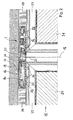
- FIG. 1 an embodiment of a drive unit in the form of a Dahlpolmotors 1 is shown in a cross-sectional view.
- the drive unit can be used to drive a turnstile of a revolving door application.
- the drive unit is arranged, for example, on the underside of a structural component 13 and forms an electronically commutated multi-pole motor 1 with a number of coil elements 10, which correspond to a number of magnetic elements 11.
- the coil elements 10 and the magnetic elements 11 are arranged between a stator part 12 and a rotor part 14.
- the stator 12 is exemplified disk-shaped and has individual protruding areas.
- the outer circumference of the Topfmantelabiteses 20 corresponds to the final, circumferential edge of the approximately disc-shaped stator 12. Due to the fact that the rotor part 14 is pot-shaped by the Topfmantelab bainites 20, formed between the stator 12 and the rotor part 14, an installation space in which the coil elements 10 and the magnetic elements 11 are arranged.
- the coil elements 10 are arranged on a structure section 31 of the stator part 12, and the structure section 31 is designed as a section running around the drive axis 17 and thus forms the circular path, on which a plurality of coil elements 10 are distributed over the circumference are, by the cross-sectional view only two coil elements 10 are shown by way of example.
- the magnetic elements 11 are accommodated on the inside in the pot casing section 20, and distributed over the circumference of the rotor part 14 is a plurality of magnetic elements 11, which corresponds to the plurality of coil elements 10.
- the electronic commutation of the coil elements 10 can be generated by using different Bestromungsalgorithmen the coil elements 10 on the circular path circulating magnetic fields which can migrate from coil element to coil element, whereby a drive torque between the coil elements 10 and the magnetic elements 11 is generated. Due to the arrangement of the coil elements 10 on the stator part 12 and the magnetic elements 11 on the rotor part 14, a torque between the stator 12 and the rotor part 14 is generated by the electronic commutation of the coil elements 10.
- a thrust bearing 18 and a radial bearing 19 is provided, the bearings 18 and 19 receive an insert member 32 rotatably mounted on the stator 12, and the insert member 32 is rotationally connected via screw 33 with the cup-shaped rotor member 14.
- the electronically commutated Drivepolmotor 1 has a flat, round basic structure and has an example of a ratio of height to diameter of about 1:10.
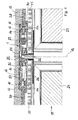
- the drive unit according to the invention is particularly advantageous for driving the turnstile of a revolving door, and the drive unit can between the turnstile and a top-side structural component 13 or between the turnstile and a bottom structural member, without requiring substantial space, as in the following FIG. 2 shown in more detail.
- FIG. 2 shows an arrangement of a drive unit to a structural component 13, wherein a turnstile 15 a revolving door 15 with a plurality of rotary blades 21 is arranged on the cup-shaped rotor part 14 in the drive unit.
- the rotor part 14 has an outer surface 22 pointing in the direction of the turnstile 15, and the rotary vanes 21 are each rigidly connected to the rotor part 14 via screw elements 34, wherein an aperture element 30 is arranged between the rotor part 14 and the rotary vanes 21.
- the stator part 12 of the electronically commutated Drivepolmotors 1 is connected in a manner not shown in detail with the structural component 13 at this holding, wherein the Dahlpolmotor 1 is arranged on the underside of the structural component 13.
- the low overall height of the drive unit can be bridged by brush elements 35, which are arranged outside the Drivepolmotors 1 between the rotary blades 21 and the structural component 13.
- the brush elements 35 can be fastened to the rotary blades 21 and grind on the structural component 13.
- the rotary vanes 21 have frame profiles 39, by means of which the rotary vanes 21 are attached by means of screw elements 34 to the rotor part 14, and between the rotary vanes 21 and the rotor part 14 is shown an aperture element 30 which can serve as a decorative trim.
- the exemplary embodiment also shows a control unit 16, which is arranged in the installation space between the stator part 12 and the rotor part 14. Also shown is an electrical line 26, which is guided via a rotary feedthrough 25 from the turnstile 15 to the control unit 16.
- the Rotary feedthrough 25 permits electrical contacting of a section of the electrical line 26 rotating with the turnstile 15 with a section of the electrical line 26 resting in the stator section 12.
- the control unit 16 can be connected to sensor elements via the electrical line 26 and received in the turnstile 15 are and therefore rotate about the drive shaft 17 with the turnstile 15.
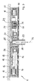
- FIG. 3 shows a further embodiment of the drive unit in a lower-side arrangement on a structural component 13.
- the drive unit has a stator part 12 in a substantially disc-shaped design, and a rotor part 14, which has a cup-shaped design.
- a number of coil elements 10 are arranged on the stator part 12, and a number of magnetic elements 11 are arranged on the rotor part 14, wherein the magnetic elements 11 are located on the outside of the coil elements 10.
- On the rotor part 14, a further diaphragm element 30 is arranged.
- a control unit 16 which is connected to an electrical line 26, and the electrical line 26 is divided by a rotary feedthrough 25 in a stationary part and in a co-rotating about a drive axis 17 part.
- the rotary feedthrough 25 is integrated in the multi-pole motor 1 and according to the embodiment shown in an output shaft 23.
- the output shaft 23 is rotationally connected to the insert member 32.
- the output shaft 23 is exemplified as a splined shaft and a turnstile 15 can be connected to the rotating drive to the drive shaft 17 to the output shaft 23.
- a further blocking device 29 is shown, which is received on the stator 12.
- the blocking device 29 comprises a blocking element 36, which can perform a lifting movement by appropriate activation in order to lock in a receiving opening 37 in the rotor part 14.
- the blocking device 29 comprises a magnetic coil 38, and if this is energized, then the blocking element 36 exerts a lifting movement into the receiving opening 37. If the blocking device 29 is activated, rotation of the rotor part 14 relative to the stator part 12 about the drive axle 17 is prevented, so that the turnstile 15 connected to the rotor part 14 is also blocked.
- the embodiment of the drive unit allows a connection of the hub 15 of the revolving door with the output shaft 23, as in the following FIG. 4 shown in more detail.
- FIG. 4 shows the embodiment of the drive unit in an arrangement on the structural component 13 by a receiving pot 27, which serves as a mounting adapter.
- the receiving pot 27 is thereby admitted to the structural component 13 by a certain amount, and by the receiving pot 27 further underside elements 28 are held on the underside of the structural component 13.
- an adapter element 24 connects, which is designed as an adapter cross and the rotary blades 21 of the turnstile 15 are arranged on the arms of the adapter element 24.
- the turnstile 15 may exemplarily have two, three, four or more rotary blades 21.
- an aperture element 30, which is arranged on the underside of the rotor part 14, wherein on the upper edge of the rotary blades 21 brush elements 35 are arranged, which bridge the vertical gap between the rotary blades 21 and the underside of the lower ceiling elements 28 substantially.
- the control unit 16 can be used to control the operation of the drive unit, in particular also by evaluating signals which are output to the control unit 16 via the electrical line 26 and the rotary feedthrough 25.
- the embodiment of the drive unit also shows a blocking device 29, which can be activated in the same way as in connection with FIG. 3 already described.
- FIG. 5 finally shows a view of a revolving door 100 with a turnstile 15, which can rotate about the drive shaft 17.
- the revolving door 100 has a structural component 13, which forms a cover element of the revolving door 100, and on the underside of the structural component 13 there is arranged a drive unit, which according to the invention is designed as an electronically commutated multpolar motor 1. If the drive unit is activated, the visible part, formed by the rotor part 14, can rotate, the rotor part 14 being connected to the rotary blades 21 of the turnstile 15.
- the illustration shows the in relation to the revolving door 100 very flat design of the drive unit 1, without significant structural adjustment between the turnstile 15 and the structural component 13 can be integrated.
- the structural component 13 can be made very flat, and on the upper side of the revolving door, 100 facade elements can connect in a manner not shown in detail, without having to provide a space for a drive unit.
Abstract
Description
Die vorliegende Erfindung betrifft eine Antriebseinheit für eine Karusselltür mit einem elektronisch kommutierten Vielpolmotor, wobei der Vielpolmotor eine Anzahl von Spulenelementen und Magnetelementen aufweist und eine flache Grundstruktur besitzt. Weiterhin richtet sich die Erfindung auf die Anordnung einer solchen Antriebseinheit an einer Karusselltür sowie auf ein Verfahren zur Anordnung der Antriebseinheit.The present invention relates to a drive unit for a revolving door with an electronically commutated Vielpolmotor, wherein the Vielpolmotor has a number of coil elements and magnetic elements and has a flat basic structure. Furthermore, the invention is directed to the arrangement of such a drive unit on a revolving door and to a method for arranging the drive unit.
Die
Die Ausbildung einer Antriebseinheit für eine Karusselltür als elektronisch kommutierter Vielpolmotor ermöglicht eine besonders vorteilhafte Integration der Antriebseinheit in die Struktur der Karusselltür. Beispielsweise kann die Antriebseinheit bodenseitig montiert werden, und es ist kein großer Aufnahmeraum zur Aufnahme der Antriebseinheit im Rohbau eines Gebäudes notwendig. Die flache Ausführung der Antriebseinheit resultiert insbesondere daraus, dass der elektronisch kommutierte Vielpolmotor direkt mit dem Drehkreuz der Karusselltür verbunden werden kann, sodass die Antriebseinheit kein Getriebe aufweisen muss. Elektronisch kommutierte Vielpolmotoren besitzen jedoch Abtriebswellen, an die anzutreibende Komponenten, beispielsweise das Drehkreuz einer Karusselltür, angeordnet werden, um die Drehbewegung der Abtriebswelle auf die Komponenten zu übertragen.The formation of a drive unit for a revolving door as electronically commutated Vielpolmotor allows a particularly advantageous integration of the drive unit in the structure of the revolving door. For example, the drive unit can be mounted on the bottom side, and it is not a large receiving space for receiving the drive unit in the shell of a building necessary. The flat design of the drive unit results in particular from the fact that the electronically commutated Vielpolmotor can be connected directly to the turnstile of the revolving door, so that the drive unit does not have to have a transmission. Electronically commutated multi-pole motors, however, have output shafts to which components to be driven, for example the turnstile of a revolving door, are arranged be transmitted to the rotational movement of the output shaft to the components.
Aus der
Neuere Karusselltüren erfordern Antriebseinheiten, die sehr flach ausgeführt sein müssen. Die Verwendung eines Getriebes in Verbindung mit einer Abtriebswelle bewirkt dabei bereits eine erhebliche Vergrößerung der Bauhöhe der Antriebseinheit in Drehachsenrichtung des Drehkreuzes, und insbesondere bei bodenmontierten Antriebseinheiten, jedoch auch bei deckenmontierten Antriebseinheiten führen große Bauhöhen häufig zu konstruktiven, jedoch auch zu ästhetischen Nachteilen bei der Einrichtung der Karusselltür beispielsweise in der Fassade eines Gebäudes.Newer revolving doors require drive units that must be very flat. The use of a transmission in conjunction with an output shaft already causes a significant increase in the height of the drive unit in the rotational axis of the turnstile, and especially in floor-mounted drive units, but also in ceiling-mounted drive units large heights often lead to constructive, but also to aesthetic disadvantages in the device the revolving door, for example, in the facade of a building.
Aufgabe der Erfindung ist es, eine Antriebseinheit für eine Karusselltür, eine Anordnung einer Antriebseinheit in einer Karusselltür sowie eine Karusselltür mit einer solchen Antriebseinheit zu schaffen, die eine geringe Bauhöhe aufweist und einfach ausgeführt ist. Insbesondere ist es die Aufgabe der Erfindung, eine Antriebseinheit mit einem elektronisch kommutierten Vielpolmotor derart weiterzubilden, dass sich die Anordnung des Vielpolmotors in der Karusselltür und insbesondere an das Drehkreuz vereinfacht ausführen lässt.The object of the invention is to provide a drive unit for a revolving door, an arrangement of a drive unit in a revolving door and a revolving door with such a drive unit, which has a low overall height and is simple. In particular, it is the object of the invention to further develop a drive unit with an electronically commutated Vielpolmotor such that the arrangement of the Vielpolmotors in the revolving door and in particular to the turnstile can run simplified.
Diese Aufgabe wird ausgehend von einer Antriebseinheit für eine Karusselltür gemäß den bekannten Merkmalen des Anspruches 1, ausgehend von einer Anordnung einer Antriebseinheit gemäß Anspruch 12 und ausgehend von einem Verfahren zur Anordnung einer Antriebseinheit gemäß Anspruch 15 mit den jeweils kennzeichnenden Merkmalen gelöst. Vorteilhafte Weiterbildungen der Erfindung sind in den abhängigen Ansprüchen angegeben.This object is achieved starting from a drive unit for a revolving door according to the known features of
Die Erfindung schlägt eine Antriebseinheit für eine Karusselltür mit einem elektronisch kommutierten Vielpolmotor mit einer Anzahl von Spulenelementen und mit einer Anzahl von Magnetelementen vor, wobei der Vielpolmotor eine flach ausgebildete Grundstruktur aufweist und einen scheibenförmigen oder topfförmigen Statorteil umfasst, der an einem ruhenden Strukturbauteil anordbar ist, und ferner aufweisend einen scheibenförmigen oder topfförmigen Rotorteil, der planparallel zum Statorteil angeordnet ist und der mit einem Drehkreuz der Karusselltür antreibend verbindbar ist, wobei die Spulenelemente und die Magnetelemente im Bereich zwischen dem Statorteil und dem Rotorteil aufgenommen sind.The invention proposes a drive unit for a revolving door with an electronically commutated Vielpolmotor with a number of coil elements and with a number of magnetic elements, wherein the Vielpolmotor has a flat-shaped basic structure and comprises a disc-shaped or cup-shaped stator part, which can be arranged on a static structural component, and further comprising a disc-shaped or pot-shaped rotor part, which is arranged plane-parallel to the stator and which is drivingly connected to a turnstile of the revolving door, wherein the coil elements and the magnetic elements are received in the region between the stator and the rotor part.
Die Erfindung geht dabei von dem Gedanken aus, den elektronisch kommutierten Vielpolmotor getriebelos mit dem Drehkreuz der Karusselltür zu verbinden und auf einfache Weise den Statorteil an einem ruhenden Strukturbauteil insbesondere der Karusselltür, jedoch beispielsweise auch an der Fassade, in der die Karusselltür eingebracht ist, anzuordnen. Der Rotorteil kann dabei auf ebenfalls einfache Weise direkt mit dem Drehkreuz der Karusselltür in direkter Verbindung gebracht sein und das Drehkreuz somit lagern. Dies wird dadurch möglich, dass der elektronisch kommutierte Vielpolmotor erfindungsgemäß im Wesentlichen aus zwei scheibenförmigen oder topfförmigen Teilen ausgeführt wird, und die Spulenelemente sowie die Magnetelemente werden zwischen den scheibenförmigen oder topfförmigen Teilen angeordnet. Der Statorteil und der Rotorteil bilden dabei gemeinsam zugleich das Gehäuse des Vielpolmotors. Insbesondere dadurch kann der elektronisch kommutierte Vielpolmotor besonders flach ausgebildet werden, wobei die scheibenförmigen oder topfförmigen Teile des Statorteils und des Rotorteils nicht zwingend den gleichen Durchmesser aufweisen müssen, und die Teile können sich gegenseitig radial überragen. Durch die scheibenförmige Grundstruktur des Vielpolmotors entsteht eine Art Drehteller, der sich auf vorteilhafte Weise zwischen dem Strukturbauteil und dem Drehkreuz der Karusselltür anordnen lässt. Das Strukturbauteil kann dabei sowohl deckenseitig als auch bodenseitig des Drehkreuzes vorhanden sein, sodass der Vielpolmotor sowohl deckenseitig als auch bodenseitig in oder an der Karusselltür anordbar ist. Ein besonderer Vorteil entsteht insbesondere durch die scheibenförmige oder tropfenförmige Ausbildung des Rotorteils, sodass dieser ohne weitere konstruktive Maßnahmen relativ zum Drehkreuz derart angeordnet werden kann, dass die Rotationsachse des Drehkreuzes eine Orthogonale auf der Erstreckungsebene des scheibenförmigen oder topfförmigen Rotorteils bildet, und die Rotationsachse des Rotorteils kann mit der Rotationsachse des Drehkreuzes zusammenfallen.The invention is based on the idea to connect the electronically commutated Vielpolmotor gearless with the turnstile of the revolving door and to easily arrange the stator on a stationary structural component in particular the revolving door, but for example, on the facade in which the revolving door is introduced , The rotor part can be brought in direct connection with the turnstile of the revolving door in a likewise simple manner and thus store the turnstile. This is made possible by the fact that the electronically commutated Vielpolmotor according to the invention is carried out essentially of two disc-shaped or cup-shaped parts, and the coil elements and the magnetic elements are between the disc-shaped or cup-shaped parts arranged. The stator and the rotor part together form at the same time the housing of Vielpolmotors. In particular characterized the electronically commutated Vielpolmotor can be made particularly flat, the disc-shaped or pot-shaped parts of the stator and the rotor part does not necessarily have to have the same diameter, and the parts can project beyond each other radially. The disc-shaped basic structure of the Vielpolmotors creates a kind of turntable, which can be arranged in an advantageous manner between the structural component and the turnstile of the revolving door. The structural component can be present both on the ceiling side and on the floor side of the turnstile, so that the Vielpolmotor can be arranged both on the ceiling side and on the bottom side in or on the revolving door. A particular advantage arises in particular by the disc-shaped or teardrop-shaped design of the rotor part, so that it can be arranged relative to the hub without further constructive measures such that the axis of rotation of the hub forms an orthogonal on the plane of extension of the disc-shaped or pot-shaped rotor part, and the axis of rotation of the rotor part can coincide with the axis of rotation of the turnstile.
Vielpolmotoren sind auch unter der Bezeichnung der Torquemotoren bekannt und weisen grundsätzlich auf einer Kreisbahn angeordnete Spulenelemente auf, die ebenfalls auf einer Kreisbahn angeordneten Magnetelementen gegenüberstehen, beispielsweise innenseitig, außenseitig oder axial gegenüberstehend, sodass ein hochpoliger, drehmomentstarker Direktantrieb gebildet ist.Vielpolmotoren are also known under the name of the torque motors and basically have arranged on a circular path coil elements which are also disposed on a circular path arranged magnetic elements, for example on the inside, outside or axially opposite, so that a high-pole, high-torque direct drive is formed.
Mit besonderem Vorteil kann das Verhältnis aus Höhe zu Durchmesser der im Wesentlichen runden, flach ausgebildeten Grundstruktur des elektronisch kommutierten Vielpolmotors einen Wert von wenigstens 1:3, vorzugsweise von wenigstens 1:4, besonders bevorzugt von wenigstens 1:5 und am meisten bevorzugt von 1:8 und mehr aufweisen. Das Verhältnis aus Höhe zu Durchmesser ergibt sich durch den parallelen Abstand des scheibenförmigen oder topfförmigen Statorteils zum scheibenförmigen oder topfförmigen Rotorteil des Vielpolmotors zum Durchmesser des Statorteils und/oder des Rotorteils. Dadurch, dass die Spulenelemente und die Magnetelemente zwischen dem Statorteil und dem Rotorteil angeordnet sind, lassen sich erst die Verhältnisse aus Höhe zu Durchmesser von bis zu 1:8 und mehr erreichen, und es hat sich gezeigt, dass sogar Grundstrukturen von Vielpolmotoren als Antrieb für Karusselltüren zum Einsatz kommen können, die ein Verhältnis aus Höhe zu Durchmesser von mehr als 1:12 erreichen können.With particular advantage, the ratio of height to diameter of the substantially round, flat-shaped basic structure of the electronically commutated Vielpolmotors a value of at least 1: 3, preferably of at least 1: 4, more preferably of at least 1: 5, and most preferably of 1: 8 and more. The ratio of height to diameter results from the parallel distance of the disc-shaped or pot-shaped stator part to the disk-shaped or cup-shaped rotor part of the Vielpolmotors to the diameter of the stator and / or the rotor part. Due to the fact that the coil elements and the magnetic elements are arranged between the stator part and the rotor part, the ratios of height to diameter of up to 1: 8 and more can only be achieved, and it has been shown that even basic structures of poly pole motors are the driving force for Revolving doors can be used, which can reach a ratio of height to diameter of more than 1:12.
Die flache, scheibenförmige Bauform des Vielpolmotors bedingt dabei den positiven Effekt eines hohen erzielbaren, für den Betrieb einer Karusselltür auch notwendigen Drehmomentes, da der umlaufende Luftspaltradius zwischen den Spulenelementen und den Magnetelementen sehr groß gestaltet werden kann, insbesondere wenn der Vielpolmotor als Außenläufer ausgebildet ist.The flat, disk-shaped design of Vielpolmotors thereby causes the positive effect of a high achievable, for the operation of a revolving door also necessary torque, since the circumferential air gap radius between the coil elements and the magnetic elements can be made very large, especially if the Vielpolmotor is designed as an external rotor.
Als scheibenförmige Gestalt wird vorliegend ein flacher Zylinder bezeichnet, bei dem der Durchmesser mehrfach größer ist als die Höhe. Beispielsweise kann der Vielpolmotor einen Durchmesser von ca. 500 mm und einen Höhe von ca. nur 40 mm aufweisen. Weiterhin ist das Merkmal einer scheibenförmigen Gestalt auch dann gegeben, wenn ein Vielpolmotor mit primär scheibenförmiger Gestalt absichtlich zu einer anderen ähnlichen Form umgestaltet wird. Beispielsweise kann ein flacher, mehreckiger Stumpf den an sich runden Statorteil oder Rotorteil umschließen oder beispielsweise der Statorteil oder auch der Rotorteil weist eine von einer Tellerform abweichende, unrunde Gestalt auf, beispielsweise einen flachen Kubus. Eine solche Umgestaltung kann erfolgen durch Umschließen des Rotorteils oder des Statorteils mit einem entsprechend geformten Gehäuse oder durch entsprechende Umgestaltung der Spulenkerne.In the present case, a disk-shaped shape is a flat cylinder in which the diameter is several times greater than the height. For example, the Vielpolmotor have a diameter of about 500 mm and a height of about 40 mm. Furthermore, the feature of a disc-shaped shape is also given when a Vielpolmotor primary disk-shaped shape is deliberately redesigned to another similar shape. For example, a flat, polygonal stump enclose the per se round stator or rotor part or for example, the stator or the rotor part has a deviating from a plate shape, non-circular shape, for example, a flat Cube. Such a transformation can be carried out by enclosing the rotor part or the stator part with a correspondingly shaped housing or by a corresponding transformation of the coil cores.
Ein weiterer, besonderer Vorteil der erfindungsgemäßen Antriebseinheit wird dadurch erreicht, dass eine Steuereinheit des Vielpolmotors ebenfalls zwischen dem Statorteil und dem Rotorteil aufgenommen werden kann. Die Steuereinheit kann dabei sowohl zur Leistungsbereitstellung, Kommutierung und Ansteuerung für den Grundbetrieb des Vielpolmotors, jedoch auch zur Signalverarbeitung für die Steuerung des Vielpolmotors ausgebildet sein, beispielsweise für eine Start/Stoppfunktion, eine Notausfunktion oder zur Drehüberwachung der Drehung des Drehkreuzes der Karusselltür. Durch die Integration der Steuereinheit des Vielpolmotor in den Raum zwischen dem Statorteil und dem Rotorteil entsteht eine anschlussfertige, modulartige Antriebseinheit, die lediglich noch mit einer Leistungsversorgung und mit Signalanschlüssen für beispielsweise ein Interfacemodul zur externen Steuerung der Antriebseinheit verbunden werden muss.Another particular advantage of the drive unit according to the invention is achieved in that a control unit of the multi-pole motor can likewise be accommodated between the stator part and the rotor part. The control unit can be designed both for power supply, commutation and control for the basic operation of Vielpolmotors, but also for signal processing for the control of Vielpolmotors, for example for a start / stop function, an emergency stop or rotation monitoring of the rotation of the turnstile of the revolving door. The integration of the control unit of the Vielpolmotor in the space between the stator and the rotor part creates a ready to connect, modular drive unit, which only has to be connected to a power supply and signal connections for example, an interface module for external control of the drive unit.
Ein weiterer wesentlicher Vorteil wird dadurch erreicht, dass der Rotorteil am Statorteil um eine insbesondere imaginäre Antriebsachse drehbar gelagert aufgenommen ist. Dabei kann zwischen dem Statorteil und dem Rotorteil wenigstens ein Lager, insbesondere wenigstens ein Axiallager und/oder wenigstens ein Radiallager, angeordnet werden. Der Statorteil befindet sich dabei in starrer Anordnung am Strukturbauteil, das Bestandteil der Karusselltür, beispielsweise des Rahmens der Karusselltür, jedoch auch Bestandteil der gesamten Fassade eines Gebäudes sein kann. An diesem ruhenden Statorteil kann der Rotorteil über eine Lageranordnung drehbar aufgenommen sein, und mit dem Rotorteil ist das Drehkreuz der Karusselltür verbindbar. Durch die Verwendung eines Axiallager kann der besondere Vorteil erreicht werden, dass vom Strukturbauteil auf das Drehkreuz Kräfte übertragen werden können, und beispielsweise kann das Strukturbauteil Bestandteil der oberseitigen Rahmenkonstruktion der Karusselltür sein, die über das Axiallager auf dem Drehkreuz abgestützt wird, ohne dass die Drehbeweglichkeit des Drehkreuzes durch die Last, die über den Vielpolmotor abgestützt wird, beeinträchtigt wird. Folglich kann insbesondere das Axiallager überdimensioniert ausgestaltet werden, und die Rahmenkonstruktion der Karusselltür kann so ausgelegt werden, dass eine Kraftübertragung durch das Drehkreuz und den Vielpolmotor in Richtung der Drehachse des Drehkreuzes, die mit der Antriebsachse des Vielpolmotors zusammenfällt, berücksichtigt werden kann. Das Drehkreuz kann dabei zwei, drei, vier oder mehr Drehflügel aufweisen und muss nicht zwingend die Grundform eines Kreuzes aufweisen.Another essential advantage is achieved in that the rotor part is received rotatably mounted on the stator part about a particular imaginary drive axle. In this case, at least one bearing, in particular at least one thrust bearing and / or at least one radial bearing, can be arranged between the stator part and the rotor part. The stator is located here in a rigid arrangement on the structural component, which may be part of the revolving door of a part of the revolving door, for example, the frame of the revolving door, but also part of the entire facade of a building. At this stationary stator part of the rotor part can be rotatably received via a bearing assembly, and with the rotor part of the turnstile of the revolving door is connected. By using a thrust bearing, the particular advantage can be achieved that forces can be transmitted from the structural component to the turnstile, and for example, the structural component part of the upper-side frame structure of the revolving door, which is supported via the thrust bearing on the turnstile, without the rotational mobility of the hub through the load, the is supported by the Vielpolmotor is impaired. Consequently, in particular, the thrust bearing can be made oversized, and the frame structure of the revolving door can be designed so that a power transmission through the turnstile and the Vielpolmotor in the direction of the axis of rotation of the hub, which coincides with the drive axis of the Vielpolmotors, can be considered. The turnstile can have two, three, four or more rotary blades and does not necessarily have the basic shape of a cross.
Nach einer weiteren vorteilhaften Ausführungsform der Antriebseinheit können die Spulenelemente relativ zu den Magnetelementen radial innenliegend angeordnet sein. Die Spulenelemente können Wicklungskörper aufweisen, die so am Statorteil angeordnet sind, dass diese im Wesentlichen radial verlaufend zwischen dem Statorteil und dem Rotorteil ausgerichtet sind. Werden die Magnetelemente relativ zu den Spulenelementen radial außenseitig angeordnet, so entsteht eine vorteilhafte, insbesondere drehmomentstarke Ausgestaltung des Vielpolmotors, der hierdurch einen sogenannten Außenläufer bildet. Dies ist insbesondere dadurch begründet, dass der Magnetspalt zwischen den Magnetelementen und den Spulenelementen einen vergrößerten Abstand zur Antriebsachse der Antriebseinheit aufweist. Dadurch, dass die Magnetelemente kleinere Abmessungen aufweisen als die Spulenelemente, kann der Luftspalt zwischen den Spulenelementen und den Magnetelementen in Bezug auf die Antriebsachse nach außen gelegt werden, indem die Magnetelemente relativ zu den Spulenelementen außenseitig angeordnet werden, sodass der Luftspaltradius vergrößert ist.According to a further advantageous embodiment of the drive unit, the coil elements can be arranged radially inwardly relative to the magnetic elements. The coil elements may comprise winding bodies which are arranged on the stator part in such a way that they are aligned essentially radially between the stator part and the rotor part. If the magnetic elements are arranged radially on the outside relative to the coil elements, then an advantageous, in particular high-torque configuration of the poly pole motor is created, which thereby forms a so-called external rotor. This is due in particular to the fact that the magnetic gap between the magnetic elements and the coil elements has an increased distance from the drive axis of the drive unit. Characterized in that the magnetic elements have smaller dimensions than the coil elements, the air gap between the coil elements and the magnetic elements with respect to the drive axis can be placed outside by the magnetic elements be arranged outside relative to the coil elements, so that the air gap radius is increased.
Die Spulenelemente können ruhend am Statorteil angeordnet sein, und der Rotorteil kann eine Topfform mit einem Topfmantelabschnitt aufweisen, der den scheibenförmigen Statorteil im Wesentlichen seitlich abdeckt bzw. diesen umschließt. Dabei können die Magnetelemente innenseitig im Topfmantelabschnitt angeordnet werden, wobei die Spulenelemente am Statorteil angeordnet sind. Werden Rotorteil und Statorteil parallel beabstandet zueinander montiert, so können sich die Spulenelemente und die Magnetelemente in radialer Richtung gegenüberstehen.The coil elements can be arranged resting on the stator part, and the rotor part can have a pot shape with a pot shell section which covers the disk-shaped stator part substantially laterally or surrounds it. In this case, the magnetic elements can be arranged on the inside in Topfmantelabschnitt, wherein the coil elements are arranged on the stator. If rotor part and stator part are mounted parallel to one another at a distance from one another, then the coil elements and the magnetic elements can face each other in the radial direction.
Der Statorteil kann ruhend am Strukturbauteil angeordnet sein, und der Rotorteil kann zur Anbindung des Drehkreuzes und insbesondere der Drehflügel ausgebildet sein, wobei die Drehflügel vorzugsweise direkt mit der äußeren Außenfläche des Rotorteils verbindbar sind. Insbesondere dann, wenn der Rotorteil scheibenförmig oder topfförmig ausgebildet ist, weist dieser einen flachen, insbesondere planen Bodenteil auf, der eine Außenfläche aufweist, die in Richtung der Drehflügel des Drehkreuzes weist. Somit kann auf besonders einfache Weise der Rotorteil mit dem Drehkreuz verbunden werden. Beispielsweise können die Drehflügel einzeln mit dem Rotorteil verbunden, insbesondere verschraubt werden. Auch ist es denkbar, die Drehflügel zunächst starr miteinander zu verbinden, sodass ein Drehkreuz entsteht, und das Drehkreuz wird mit dem Rotorteil verbunden. Besonders vorteilhaft werden jedoch die Drehflügel einzeln mit dem Rotorteil verbunden, wobei Aufnahmeelemente, beispielsweise Aufnahmeprofile, vorgesehen sein können, über die die Drehflügel mit der Außenseite des Rotorteils verbunden werden.The stator part can be arranged resting on the structural component, and the rotor part can be designed to connect the turnstile and in particular the rotary vanes, wherein the rotary vanes are preferably directly connected to the outer outer surface of the rotor part. In particular, when the rotor part is disc-shaped or pot-shaped, this has a flat, in particular planar bottom part, which has an outer surface facing in the direction of the rotary wing of the turnstile. Thus, the rotor part can be connected to the turnstile in a particularly simple manner. For example, the rotary blades can be individually connected to the rotor part, in particular screwed. It is also conceivable first rigidly connect the rotary wing with each other, so that a turnstile is formed, and the turnstile is connected to the rotor part. Particularly advantageous, however, the rotary blades are individually connected to the rotor part, wherein receiving elements, such as receiving profiles, may be provided, via which the rotary blades are connected to the outside of the rotor part.
Nach einer weiteren Variante kann der Vielpolmotor eine Abtriebswelle umfassen, die mit dem Rotorteil drehstarr verbunden ist und die sich in der Antriebsachse erstreckt, in der das Drehkreuz rotiert. Das Drehkreuz kann mit der Abtriebswelle verbunden werden, wofür insbesondere ein Adapterelement zum Einsatz kommen kann. Das Adapterelement kann beispielsweise ein Adapterkreuz bilden, und das Adapterkreuz bildet Aufnahmearme, an denen einzelne Drehflügel angebracht werden können.According to another variant, the Vielpolmotor may comprise an output shaft which is rotationally connected to the rotor part and which extends in the drive axis in which rotates the turnstile. The turnstile can be connected to the output shaft, for which in particular an adapter element can be used. The adapter element may for example form an adapter cross, and the adapter cross forms receiving arms to which individual rotary blades can be attached.
Gemäß einer vorteilhaften Weiterbildung der erfindungsgemäßen Antriebseinheit kann der Vielpolmotor wenigstens eine Drehdurchführung aufweisen, mittels der durch wenigstens eine elektrische Leitung elektrische Mittel im Vielpolmotor, insbesondere die Steuereinheit, mit einem mit dem Rotorteil drehenden Element, insbesondere mit dem Drehkreuz, elektrisch verbindbar ist. Die Drehdurchführung kann mit besonderem Vorteil im Vielpolmotor integriert angeordnet sein. Die im Vielpolmotors aufgenommene Steuereinheit wird vorzugsweise am Statorteil ruhend angeordnet, und um eine elektrische Verbindung zwischen dem rotierenden Drehkreuz und der ruhenden Steuereinheit zu schaffen, kann die Drehdurchführung vorgesehen sein, die insbesondere zwischen dem Rotorteil und dem Statorteil angeordnet werden kann. Weist der Vielpolmotor eine Abtriebswelle auf, so kann diese als Hohlwelle ausgeführt sein, und die Drehdurchführung kann innenseitig in der hohl ausgebildeten Abtriebswelle aufgenommen sein oder zumindest die elektrische Leitung kann durch die Hohlwelle verlaufen. Die elektrischen Leitungen können insbesondere durch die Hohlwelle in das Drehkreuz geführt werden, und im Drehkreuz können Sensoren, elektrische Schalter, Notschalter oder dergleichen angebracht sein, die über die sich zwischen dem Statorteil und dem Rotorteil befindende Drehdurchführung mit der elektrischen Steuereinheit auch während der Rotationsbewegung des Drehkreuzes elektrisch verbunden sind.According to an advantageous development of the drive unit according to the invention, the Vielpolmotor may comprise at least one rotary feedthrough, by means of at least one electrical line electrical means in Vielpolmotor, in particular the control unit, with an element rotating with the rotor member, in particular with the turnstile, is electrically connectable. The rotary feedthrough can be arranged integrated with particular advantage in Vielpolmotor. The recorded in Vielpolmotors control unit is preferably arranged resting on the stator, and to provide an electrical connection between the rotating hub and the stationary control unit, the rotary feedthrough may be provided, which can be arranged in particular between the rotor part and the stator. If the multi-pole motor has an output shaft, then it can be designed as a hollow shaft, and the rotary feedthrough can be accommodated on the inside in the hollow output shaft or at least the electric line can run through the hollow shaft. The electrical lines can be guided in particular through the hollow shaft in the turnstile, and in the turnstile sensors, electrical switches, emergency or the like may be attached, which is located on the located between the stator and the rotor part rotary union with the electrical control unit during the rotational movement of the Turnstile are electrically connected.
Der elektronisch kommutierte Vielpolmotor kann bodenseitig in die Karusselltür integriert werden, sodass sich der Vielpolmotor gemeinsam wenigstens abschnittsweise über die Höhe eines auf einem Rohbau aufgebauten Estrich erstreckt, mit besonderem Vorteil kann der elektronisch kommutierte Vielpolmotor jedoch an der Unterseite eines Strukturbauteils sichtbar angeordnet werden, das sich oberhalb des Drehkreuzes der Karusselltür befindet. Die Sichtbarkeit ist dabei insbesondere für sich im Drehkreuz befindliche Personen gegeben. Der sichtbare Teil des Vielpolmotors wird dabei insbesondere durch den scheibenförmigen oder topfförmigen Rotorteil gebildet, der mit besonderem Vorteil eine entsprechende Dekoroberfläche oder auch ein zusätzliches Blendenelement aufweisen kann. Ein weiterer Vorteil durch die sichtbare Anordnung des Vielpolmotors kann dadurch erreicht werden, dass beispielsweise Beleuchtungsmittel im Motor integriert werden können, beispielsweise kann der scheibenförmige oder topfförmige Rotorteil wenigstens teilweise aus einem lichttransparenten Material ausgebildet sein, und zwischen dem Statorteil und dem Rotorteil können Leuchtmittel angeordnet werden. Auch ist es denkbar, den scheibenförmigen Vielpolmotor mit einem Leuchtrand einzufassen, wobei mit besonderem Vorteil sämtliche Leuchtmittel durch Halbleiter-Leuchtmittel gebildet sein können.The electronically commutated Vielpolmotor can be integrated into the bottom side of the revolving door, so that the Vielpolmotor together extends at least in sections on the height of a scaffold built on a shell, with particular advantage of the electronically commutated Vielpolmotor can be arranged visible on the underside of a structural component that located above the turnstile of the revolving door. The visibility is given especially for persons located in the turnstile. The visible part of the Vielpolmotors is formed in particular by the disc-shaped or cup-shaped rotor part, which may have a particular decorative surface or an additional aperture element with particular advantage. Another advantage of the visible arrangement of the Vielpolmotors can be achieved that, for example, lighting means can be integrated in the engine, for example, the disc-shaped or cup-shaped rotor part may be at least partially formed of a light transparent material, and between the stator and the rotor part bulbs can be arranged , It is also conceivable to enclose the disc-shaped Vielpolmotor with a luminous edge, with particular advantage all bulbs can be formed by semiconductor bulbs.
Schließlich kann der Vielpolmotor noch einen Positions- oder Winkelgeber aufweisen, dieser dient der Kommutierung und Bestimmung von Winkelpositionen und der Drehgeschwindigkeit des Drehkreuzes.Finally, the Vielpolmotor can still have a position or angle encoder, this is used for commutation and determination of angular positions and the rotational speed of the turnstile.
Die vorliegende Erfindung richtet sich ferner auf eine Anordnung einer Antriebseinheit für eine Karusselltür mit einem elektronisch kommutierten Vielpolmotor mit einer Anzahl von Spulenelementen und mit einer Anzahl von Magnetelementen, wobei der Vielpolmotor eine flach ausgebildete Grundstruktur aufweist und einen scheibenförmigen oder topfförmigen Statorteil umfasst, der an einem ruhenden Strukturbauteil anordbar ist, und ferner aufweisend einen scheibenförmigen oder topfförmigen Rotorteil, der planparallel zum Statorteil angeordnet ist und der mit einem Drehkreuz der Karusselltür antreibend verbindbar ist, wobei die Spulenelemente und die Magnetelemente im Bereich zwischen dem Statorteil und dem Rotorteil aufgenommen sind. Zur Anordnung der Antriebseinheit kann ein Aufnahmetopf vorgesehen sein, mit dem die Antriebseinheit insbesondere wenigstens teilweise in das Strukturbauteil eingelassen an diesem angeordnet ist, wobei der Vielpolmotor im Aufnahmetopf aufgenommen ist. Der Aufnahmetopf kann einen Bodenbereich, einen Mantelbereich und insbesondere einen Kragenbereich umfassen, und der Kragenbereich kann sich in einer Ebene parallel zum Bodenbereich erstrecken. Der Bodenbereich muss dabei nicht zwangsläufig geschlossen ausgeführt sein, und der Aufnahmetopf kann auch einen offenen Boden umfassen, sodass in Abwandlung zu einem Aufnahmetopf ein Aufnahmering zur Aufnahme der Antriebseinheit gebildet sein kann.The present invention is further directed to an arrangement of a drive unit for a revolving door with an electronically commutated Vielpolmotor with a number of coil elements and with a number of magnetic elements, wherein the Vielpolmotor has a flat-shaped basic structure and a disc-shaped or cup-shaped Stator part which can be arranged on a stationary structural component, and further comprising a disc-shaped or cup-shaped rotor part, which is arranged plane-parallel to the stator and drivingly connected to a turnstile of the revolving door, wherein the coil elements and the magnetic elements in the region between the stator and the Rotor part are included. For arranging the drive unit, a receiving pot may be provided, with which the drive unit is at least partially embedded in the structural component, in which case the multipolar motor is accommodated in the receiving pot. The receptacle may include a bottom portion, a skirt portion, and more particularly a collar portion, and the collar portion may extend in a plane parallel to the bottom portion. The bottom area does not necessarily have to be closed, and the receiving pot can also comprise an open bottom, so that, as a modification to a receiving pot, a receiving ring for receiving the drive unit can be formed.
Mit weiterem Vorteil kann die Antriebseinheit deckenseitig in der Karusselltür integriert sein, wobei unterseitig des Strukturbauteils wenigstens ein Unterdeckenelement angeordnet werden kann, das zumindest teilweise durch den Aufnahmetopf gehalten wird und als Dekorelement dienen kann, Insbesondere dann, wenn die Antriebseinheit nicht vollständig mit dem Aufnahmetopf im Strukturbauteil eingelassen wird, kann ein vertikaler Bereich zwischen dem Kragen des Aufnahmetopfes und der Unterseite des Strukturbauteils gebildet werden, in dem das Dekorelement angeordnet, insbesondere eingehängt oder eingeschoben wird.With further advantage, the drive unit can be integrated on the ceiling side in the revolving door, wherein at least one underside element can be arranged on the underside of the structural component, which is held at least partially by the receiving pot and can serve as a decorative element, in particular if the drive unit is not completely connected to the receiving pot in the Structural component is embedded, a vertical area between the collar of the pot and the bottom of the structural component can be formed in which the decorative element is arranged, in particular mounted or inserted.
Mit dem Aufnahmetopf kann die Antriebseinheit unmittelbar unter das Strukturbauteil montiert werden, wobei die Antriebseinheit auch teilweise in das Strukturbauteil eingelassen werden kann, sodass sich die Antriebseinheit mit einem Teil ihrer Bauhöhe in das Strukturbauteil hinein erstreckt. Nach einer weiteren Variante kann der Aufnahmetopf auch derart ausgestaltet sein, dass die Antriebseinheit mit ihrer gesamten Höhe im Strukturbauteil eingelassen ist.With the receiving pot, the drive unit can be mounted directly under the structural component, wherein the drive unit can also be partially embedded in the structural component, so that the drive unit with a part of its height in the structural component extends into it. According to a further variant of the receiving pot can also be designed such that the drive unit is embedded with its entire height in the structural component.
Der Aufnahmetopf kann mit besonderem Vorteil dazu Verwendung finden, die Antriebseinheit auch nachträglich in eine bestehende Karusselltür anzuordnen, und zum Antrieb des Drehkreuzes einzusetzen. Dabei kann eine konventionelle, eine ein Motor und ein Getriebe umfassende Antriebseinheit demontiert werden, und zwischen dem Strukturbauteil, beispielsweise dem Deckenelement der Karusselltür, und dem Drehkreuz, kann mittels des Aufnahmetopfes die Antriebseinheit in die Karusselltür nachgerüstet werden.The pot can be used to particular advantage to arrange the drive unit subsequently in an existing revolving door, and to use for driving the turnstile. In this case, a conventional, a motor and a transmission comprehensive drive unit can be dismantled, and between the structural component, such as the ceiling element of the revolving door, and the turnstile, the drive unit can be retrofitted into the revolving door by means of the pot.
Weiterhin richtet sich die Erfindung auf eine Karusselltür mit einer Antriebseinheit mit einem elektronisch kommutierten Vielpolmotor mit einer Anzahl von Spulenelementen und mit einer Anzahl von Magnetelementen, wobei der Vielpolmotor eine flach ausgebildete Grundstruktur aufweist und einen scheibenförmigen oder topfförmigen Statorteil umfasst, der an einem ruhenden Strukturbauteil angeordnet ist, und ferner aufweisend einen scheibenförmigen oder topfförmigen Rotorteil, der planparallel zum Statorteil angeordnet ist und der mit einem Drehkreuz der Karusselltür antreibend verbunden ist, wobei die Spulenelemente und die Magnetelementen im Bereich zwischen dem Statorteil und dem Rotorteil aufgenommen sind. Die in Zusammenhang mit der Antriebseinheit aufgeführten weiteren Merkmale und zugehörigen Vorteile finden für die Anordnung der Antriebseinheit sowie für die Karusselltür ebenfalls auf gleiche Weise Berücksichtigung.Furthermore, the invention is directed to a revolving door with a drive unit with an electronically commutated Vielpolmotor with a number of coil elements and a number of magnetic elements, wherein the Vielpolmotor has a flat-shaped basic structure and comprises a disc-shaped or cup-shaped stator part, which is arranged on a stationary structural component is, and further comprising a disc-shaped or cup-shaped rotor part which is arranged plane-parallel to the stator and which is drivingly connected to a turnstile of the revolving door, wherein the coil elements and the magnetic elements are received in the region between the stator and the rotor part. The additional features and associated advantages listed in connection with the drive unit are likewise taken into account in the same way for the arrangement of the drive unit and for the revolving door.
Weiterhin richtet sich die Erfindung auf ein Verfahren zur Anordnung einer Antriebseinheit, wobei das Verfahren wenigstens die Schritte des Bereitstellens der Antriebseinheit, des Bereitstellens eines Aufnahmetopfes zur Aufnahme der Antriebseinheit, des Anordnens der Antriebseinheit an den Aufnahmetopf vor oder nach einem Anordnen des Aufnahmetopfes an ein oder in einem Strukturbauteil umfasst. Dabei kann insbesondere der Schritt des Anbindens eines Drehkreuzes und insbesondere von Drehflügeln an einen Rotorteil des Vielpolmotors vorgesehen werden.Furthermore, the invention is directed to a method for arranging a drive unit, wherein the method comprises at least the steps of providing the drive unit, providing a holding pot for receiving the drive unit, arranging the drive unit to the receiving pot before or after arranging the receiving pot on or in a structural component. In particular, the step of tying a turnstile and, in particular, rotary blades to a rotor part of the multi-pole motor can be provided.
Weitere, die Erfindung verbessernde Maßnahmen werden nachstehend gemeinsam mit der Beschreibung eines bevorzugten Ausführungsbeispiels der Erfindung anhand der Figuren näher dargestellt. Es zeigt:
Figur 1- ein erstes Ausführungsbeispiel einer Antriebseinheit in Anordnung an einem Strukturbauteil, wobei die Antriebseinheit als elektronisch kommutierter Vielpolmotor ausgeführt ist,
- Figur 2
- ein erstes Ausführungsbeispiel einer Antriebseinheit in Anordnung an einem Strukturbauteil, wobei ein Drehkreuz mit mehreren Drehflügeln am Rotorteil des Vielpolmotors angeordnet ist,
- Figur 3
- ein zweites Ausführungsbeispiel einer Antriebseinheit in Anordnung an einem Strukturbauteil, wobei die Antriebseinheit als elektronisch kommutierter Vielpolmotor ausgeführt ist,
- Figur 4
- das zweite Ausführungsbeispiel einer Antriebseinheit in Anordnung an einem Strukturbauteil, wobei ein Drehkreuz mit einer Anzahl von Drehflügeln mittels eines Adapterelementes am elektronisch kommutierten Vielpolmotors angeordnet ist und
- Figur 5
- eine perspektivische Ansicht einer Karusselltür mit einer Antriebseinheit gemäß der vorliegenden Erfindung.
- FIG. 1
- a first embodiment of a drive unit in arrangement on a structural component, wherein the drive unit is designed as electronically commutated Vielpolmotor,
- FIG. 2
- a first embodiment of a drive unit arranged on a structural component, wherein a turnstile is arranged with a plurality of rotary blades on the rotor part of the Vielpolmotors,
- FIG. 3
- a second embodiment of a drive unit in arrangement on a structural component, wherein the drive unit is designed as electronically commutated Vielpolmotor,
- FIG. 4
- the second embodiment of a drive unit in arrangement on a structural component, wherein a turnstile with a number of rotary blades by means of an adapter element is arranged on the electronically commutated Vielpolmotors and
- FIG. 5
- a perspective view of a revolving door with a drive unit according to the present invention.
In
Die Antriebseinheit ist beispielhaft an der Unterseite eines Strukturbauteils 13 angeordnet und bildet einen elektronisch kommutierten Vielpolmotor 1 mit einer Anzahl von Spulenelementen 10, die mit einer Anzahl von Magnetelementen 11 korrespondieren. Die Spulenelemente 10 und die Magnetelemente 11 sind zwischen einem Statorteil 12 und einem Rotorteil 14 angeordnet. Der Statorteil 12 ist beispielhaft scheibenförmig ausgebildet und weist einzelne hervorstehende Bereiche auf. Der Rotorteil 14 ist topfförmig ausgebildet und besitzt einen umlaufenden Topfmantelabschnitt 20. Der Außenumfang des Topfmantelabschnittes 20 korrespondiert dabei mit dem abschließenden, umlaufenden Rand des etwa scheibenförmigen Statorteils 12. Dadurch, dass der Rotorteil 14 durch den Topfmantelabschnitt 20 topfförmig ausgebildet ist, entsteht zwischen dem Statorteil 12 und dem Rotorteil 14 ein Einbauraum, in dem die Spulenelementen 10 und die Magnetelemente 11 angeordnet sind.The drive unit is arranged, for example, on the underside of a
Die Spulenelemente 10 sind an einem Strukturabschnitt 31 des Statorteils 12 angeordnet, und der Strukturabschnitt 31 ist als um die Antriebsachse 17 umlaufender Abschnitt ausgebildet und bildet so die Kreisbahn, an der über den Umfang verteilt eine Vielzahl von Spulenelementen 10 aufgenommen sind, wobei durch die Querschnittsdarstellung lediglich zwei Spulenelemente 10 beispielhaft gezeigt sind.The
Die Magnetelemente 11 sind innenseitig im Topfmantelabschnitt 20 aufgenommen, und über dem Umfang des Rotorteils 14 verteilt befindet sich eine Vielzahl von Magnetelementen 11, die mit der Vielzahl der Spulenelemente 10 korrespondiert.The
Durch die elektronische Kommutierung der Spulenelemente 10 können unter Ausnutzung verschiedener Bestromungsalgorithmen der Spulenelemente 10 auf der Kreisbahn umlaufende Magnetfelder erzeugt werden, welche von Spulenelement zu Spulenelement wandern können, wodurch ein Antriebsmoment zwischen den Spulenelementen 10 und den Magnetelementen 11 erzeugt wird. Durch die Anordnung der Spulenelemente 10 am Statorteil 12 und der Magnetelemente 11 am Rotorteil 14 wird durch die elektronische Kommutierung der Spulenelemente 10 ein Drehmoment zwischen dem Statorteil 12 und dem Rotorteil 14 erzeugt.The electronic commutation of the
Zur drehbaren Aufnahme des Rotorteils 14 am Statorteil 12 ist ein Axiallager 18 und ein Radiallager 19 vorgesehen, wobei die Lager 18 und 19 ein Einsatzelement 32 drehbar am Statorteil 12 aufnehmen, und das Einsatzelement 32 ist über Schraubelemente 33 mit dem topfförmigen Rotorteil 14 drehstarr verbunden.For rotatably receiving the
Der elektronisch kommutierte Vielpolmotor 1 weist eine flache, runde Grundstruktur auf und besitzt beispielhaft ein Verhältnis aus Höhe zu Durchmesser von ca. 1:10. Damit eignet sich die erfindungsgemäße Antriebseinheit besonders vorteilhaft zum Antrieb des Drehkreuzes einer Karusselltür, und die Antriebseinheit kann zwischen dem Drehkreuz und einem oberseitigen Strukturbauteil 13 oder auch zwischen dem Drehkreuz und einem bodenseitigen Strukturbauteil angeordnet werden, ohne wesentlichen Bauraum zu benötigen, wie in der folgenden
Der Statorteil 12 des elektronisch kommutierten Vielpolmotors 1 ist auf nicht näher gezeigte Weise mit dem Strukturbauteil 13 an diesem haltend verbunden, wobei der Vielpolmotor 1 unterseitig am Strukturbauteil 13 angeordnet ist. Die geringe Bauhöhe der Antriebseinheit kann über Bürstenelemente 35 überbrückt werden, die außerhalb des Vielpolmotors 1 zwischen den Drehflügeln 21 und dem Strukturbauteil 13 angeordnet sind. Die Bürstenelemente 35 können dabei an den Drehflügeln 21 befestigt sein und am Strukturbauteil 13 schleifen.The
Die Drehflügel 21 besitzen Rahmenprofile 39, über die die Drehflügel 21 mittels Schraubelementen 34 am Rotorteil 14 angebracht sind, und zwischen den Drehflügeln 21 und dem Rotorteil 14 ist ein Blendenelement 30 gezeigt, das als Dekorblende dienen kann.The
Das Ausführungsbeispiel zeigt weiterhin eine Steuereinheit 16, die im Einbauraum zwischen dem Statorteil 12 und dem Rotorteil 14 angeordnet ist. Weiterhin gezeigt ist eine elektrische Leitung 26, die über eine Drehdurchführung 25 aus dem Drehkreuz 15 zur Steuereinheit 16 geführt ist. Die Drehdurchführung 25 erlaubt dabei eine elektrische Kontaktierung eines mit dem Drehkreuz 15 drehenden Abschnittes der elektrischen Leitung 26 mit einem im Statorteil 12 ruhenden Abschnitt der elektrischen Leitung 26. Beispielsweise kann über die elektrische Leitung 26 die Steuereinheit 16 mit Sensorelementen verbunden sein, die im Drehkreuz 15 aufgenommen sind und folglich um die Antriebsachse 17 mit dem Drehkreuz 15 mitrotieren.The exemplary embodiment also shows a
Im Einbauraum zwischen dem Statorteil 12 und dem Rotorteil 14 befindet sich eine Steuereinheit 16, die mit einer elektrischen Leitung 26 verbunden ist, und die elektrische Leitung 26 ist durch eine Drehdurchführung 25 in einen ruhenden Teil und in einen um eine Antriebsachse 17 mitdrehenden Teil unterteilt. Die Drehdurchführung 25 ist im Vielpolmotor 1 und gemäß dem gezeigten Ausführungsbeispiel in einer Abtriebswelle 23 integriert.In the installation space between the
Die Abtriebswelle 23 ist mit dem Einsatzelement 32 drehstarr verbunden. Die Abtriebswelle 23 ist beispielhaft als Vielkeilwelle ausgeführt und ein Drehkreuz 15 kann zum rotierenden Antrieb um die Antriebsachse 17 mit der Abtriebswelle 23 verbunden werden.The
Im Einbauraum zwischen dem Statorteil 12 und dem Rotorteil 14 ist eine weitere Blockiereinrichtung 29 gezeigt, die am Statorteil 12 aufgenommen ist. Die Blockiereinrichtung 29 umfasst ein Blockierelement 36, das durch entsprechende Aktivierung eine Hubbewegung ausführen kann, um in einer Aufnahmeöffnung 37 im Rotorteil 14 zu verrasten. Um die Hubbewegung des Blockierelementes 36 auszulösen, umfasst die Blockiereinrichtung 29 eine Magnetspule 38, und wird diese bestromt, so übt das Blockierelement 36 eine Hubbewegung in die Aufnahmeöffnung 37 aus. Ist die Blockiereinrichtung 29 aktiviert, so wird eine Drehung des Rotorteils 14 relativ zum Statorteil 12 um die Antriebsachse 17 verhindert, sodass auch das mit dem Rotorteil 14 verbundene Drehkreuz 15 blockiert ist.In the installation space between the
Das Ausführungsbeispiel der Antriebseinheit ermöglicht eine Verbindung des Drehkreuzes 15 der Karusselltür mit der Abtriebswelle 23, wie in der folgenden
Zur Aufnahme des Vielpolmotors 1 im Aufnahmetopf 27 ist der Statorteil 12 mit dem Aufnahmetopf 27 starr verbunden, und der Rotorteil 14 ist mit der Abtriebswelle 23 drehstarr verbunden.To accommodate the
An die Abtriebswelle 23 schließt sich ein Adapterelement 24 an, das als Adapterkreuz ausgeführt ist und die Drehflügel 21 des Drehkreuzes 15 sind an den Armen des Adapterelementes 24 angeordnet. Das Drehkreuz 15 kann beispielhaft zwei, drei, vier oder mehr Drehflügel 21 aufweisen. Weiterhin gezeigt ist ein Blendenelement 30, das unterseitig am Rotorteil 14 angeordnet ist, wobei an der Oberkante der Drehflügel 21 Bürstenelemente 35 angeordnet sind, die den vertikalen Spalt zwischen den Drehflügeln 21 und der Unterseite der Unterdeckenelemente 28 im Wesentlichen überbrücken.To the
Werden die Wicklungskörper 10a der Spulenelemente 10 bestromt, so kann durch magnetische Wechselwirkung mit den Magnetelementen 11 zwischen dem Statorteil 12 und dem Rotorteil 14 ein Drehmoment erzeugt werden. Über die drehstarre Verbindung des Rotorteils 14 mit dem Drehkreuz 15 über die Abtriebswelle 23 kann das Drehkreuz 15 in Rotation versetzt werden. Dabei kann über die Steuereinheit 16 eine Steuerung des Betriebs der Antriebseinheit erfolgen, insbesondere auch unter Auswertung von Signalen, die über die elektrische Leitung 26 und die Drehdurchführung 25 an die Steuereinheit 16 abgegeben werden. Das Ausführungsbeispiel der Antriebseinheit zeigt ebenfalls eine Blockiereinrichtung 29, die auf gleiche Weise aktiviert werden kann, wie in Zusammenhang mit
Die Erfindung beschränkt sich in ihrer Ausführung nicht auf das vorstehend angegebene bevorzugte Ausführungsbeispiel. Vielmehr ist eine Anzahl von Varianten denkbar, welche von der dargestellten Lösung auch bei grundsätzlich anders gearteten Ausführungen Gebrauch macht. Sämtliche aus den Ansprüchen, der Beschreibung oder den Zeichnungen hervorgehenden Merkmale und/oder Vorteile, einschließlich konstruktiver Einzelheiten oder räumliche Anordnungen, können sowohl für sich als auch in den verschiedensten Kombinationen erfindungswesentlich sein.The invention is not limited in its execution to the above-mentioned preferred embodiment. Rather, a number of variants is conceivable, which makes use of the illustrated solution even with fundamentally different types of use. Any features and / or advantages resulting from the claims, the description or the drawings, including constructive details or spatial arrangements, can be essential to the invention, both individually and in the most diverse combinations.
- 100100
- Karusselltürrevolving door
- 11
- VielpolmotorVielpolmotor
- 1010
- Spulenelementcoil element
- 10a10a
- Wicklungskörperwinding body
- 1111
- Magnetelementmagnetic element
- 1212
- Statorteilstator
- 1313
- Strukturbauteilstructural component
- 1414
- Rotorteilrotor part
- 1515
- Drehkreuzturnstile
- 1616
- Steuereinheitcontrol unit
- 1717
- Antriebsachsedrive axle
- 1818
- Axiallagerthrust
- 1919
- Radiallagerradial bearings
- 2020
- TopfmantelabschnittPot casing section
- 2121
- Drehflügelrotary wing
- 2222
- Außenflächeouter surface
- 2323
- Abtriebswelleoutput shaft
- 2424
- Adapterelementadapter element
- 2525
- DrehdurchführungRotary union
- 2626
- elektrische Leitungelectrical line
- 2727
- Aufnahmetopfpot
- 2828
- UnterdeckenelementUnder ceiling element
- 2929
- Blockiereinrichtungblocking device
- 3030
- Blendenelementdiaphragm element
- 3131
- Strukturabschnittstructure section
- 3232
- Einsatzelementinsert element
- 3333
- Schraubelementscrew
- 3434
- Schraubelementscrew
- 3535
- Bürstenelementbrush element
- 3636
- Blockierelementblocking element
- 3737
- Aufnahmeöffnungreceiving opening
- 3838
- Magnetspulesolenoid
- 3939
- Rahmenprofilframe profile
Claims (15)
Applications Claiming Priority (1)
| Application Number | Priority Date | Filing Date | Title |
|---|---|---|---|
| DE102013000421.7A DE102013000421A1 (en) | 2013-01-14 | 2013-01-14 | Drive unit for a revolving door in a flat. disk-shaped design |
Publications (2)
| Publication Number | Publication Date |
|---|---|
| EP2754826A2 true EP2754826A2 (en) | 2014-07-16 |
| EP2754826A3 EP2754826A3 (en) | 2017-07-05 |
Family
ID=49917556
Family Applications (1)
| Application Number | Title | Priority Date | Filing Date |
|---|---|---|---|
| EP14000034.0A Pending EP2754826A3 (en) | 2013-01-14 | 2014-01-07 | Drive unit for a revolving door in a flat, disc-shaped form |
Country Status (4)
| Country | Link |
|---|---|
| US (1) | US10148144B2 (en) |
| EP (1) | EP2754826A3 (en) |
| CN (2) | CN113054772A (en) |
| DE (2) | DE102013000421A1 (en) |
Cited By (4)
| Publication number | Priority date | Publication date | Assignee | Title |
|---|---|---|---|---|
| EP3034761A1 (en) * | 2014-12-17 | 2016-06-22 | DORMA Deutschland GmbH | Revolving door |
| EP3034759A1 (en) * | 2014-12-16 | 2016-06-22 | DORMA Deutschland GmbH | Method for controlling a revolving door |
| EP3034758A1 (en) * | 2014-12-16 | 2016-06-22 | DORMA Deutschland GmbH | Revolving door |
| WO2021175968A1 (en) * | 2020-03-05 | 2021-09-10 | Assa Abloy Entrance Systems Ab | Revolving door assembly |
Families Citing this family (4)
| Publication number | Priority date | Publication date | Assignee | Title |
|---|---|---|---|---|
| DE102015008133A1 (en) | 2015-06-24 | 2016-12-29 | Landert Motoren Ag | Drive unit for an automatic revolving door |
| JP6759359B2 (en) | 2016-04-13 | 2020-09-23 | ジェネシス ロボティクス アンド モーション テクノロジーズ カナダ アンリミテッド ライアビリティ カンパニー | Axial flux electromechanical with radial inner thrust bearings and radial outer thrust bearings |
| JP6977556B2 (en) * | 2017-07-21 | 2021-12-08 | 株式会社デンソー | Rotating machine |
| DE102017122466A1 (en) * | 2017-09-27 | 2019-03-28 | Vorwerk & Co. Interholding Gmbh | Drive device with a rotary shaft, a rotor and a balancing disk |
Citations (2)
| Publication number | Priority date | Publication date | Assignee | Title |
|---|---|---|---|---|
| EP2072737A2 (en) | 2007-12-20 | 2009-06-24 | GEZE GmbH | Automatic carousel door assembly and method for operating an automatic sliding door assembly |
| DE102010024108A1 (en) | 2010-06-17 | 2011-12-22 | Dorma Gmbh + Co. Kg | Karuselltür |
Family Cites Families (12)
| Publication number | Priority date | Publication date | Assignee | Title |
|---|---|---|---|---|
| CA1266877A (en) * | 1984-09-13 | 1990-03-20 | Erich Rabe | Electronically commutated dc machine and use thereof |
| JPH0711838A (en) * | 1993-06-23 | 1995-01-13 | Sumitomo Special Metals Co Ltd | Device for driving revolving door |
| DE4429893C1 (en) * | 1994-08-25 | 1996-02-29 | Dorma Gmbh & Co Kg | Drive device for a revolving door |
| DE10259426A1 (en) * | 2002-12-06 | 2004-06-24 | Prodema Antriebstechnik Gmbh & Co. Kg | Brushless electronically-commutated DC motor for maritime applications, has permanent magnets arranged on circular path around rotor attached by bearing on base of pot-shaped stator |
| EP1541738B1 (en) * | 2003-12-10 | 2013-06-12 | LG Electronics, Inc. | Outer rotor type motor for drum type washing machine and method for fabricating the same |
| DE102004033304B4 (en) * | 2004-07-08 | 2008-04-17 | Dorma Gmbh + Co. Kg | revolving door |
| CN101208853A (en) * | 2005-03-23 | 2008-06-25 | 波峰实验室责任有限公司 | Electric machine and method of manufacture |
| CN201118405Y (en) * | 2007-01-31 | 2008-09-17 | 江福德 | An electric wheel hub electromotor |
| DE102007030508B4 (en) * | 2007-06-30 | 2014-10-16 | Schaeffler Technologies Gmbh & Co. Kg | Washing machines direct drive |
| DE102008059354A1 (en) * | 2008-11-25 | 2010-05-27 | Keiper Gmbh & Co. Kg | Drive unit for a vehicle seat |
| DE202010009004U1 (en) * | 2010-11-10 | 2012-02-14 | Steffen Söhner Gmbh | Electric pancake motor and electric bicycle or pedelec with a pancake motor |
| JP2012257413A (en) * | 2011-06-10 | 2012-12-27 | Seiko Epson Corp | Electromechanical device, robot, movable body, and manufacturing method of electromechanical device |
-
2013
- 2013-01-14 DE DE102013000421.7A patent/DE102013000421A1/en not_active Ceased
-
2014
- 2014-01-07 EP EP14000034.0A patent/EP2754826A3/en active Pending
- 2014-01-07 DE DE202014011466.8U patent/DE202014011466U1/en not_active Expired - Lifetime
- 2014-01-14 CN CN202110355238.6A patent/CN113054772A/en active Pending
- 2014-01-14 US US14/154,423 patent/US10148144B2/en active Active
- 2014-01-14 CN CN201410016191.0A patent/CN103929036A/en active Pending
Patent Citations (2)
| Publication number | Priority date | Publication date | Assignee | Title |
|---|---|---|---|---|
| EP2072737A2 (en) | 2007-12-20 | 2009-06-24 | GEZE GmbH | Automatic carousel door assembly and method for operating an automatic sliding door assembly |
| DE102010024108A1 (en) | 2010-06-17 | 2011-12-22 | Dorma Gmbh + Co. Kg | Karuselltür |
Cited By (4)
| Publication number | Priority date | Publication date | Assignee | Title |
|---|---|---|---|---|
| EP3034759A1 (en) * | 2014-12-16 | 2016-06-22 | DORMA Deutschland GmbH | Method for controlling a revolving door |
| EP3034758A1 (en) * | 2014-12-16 | 2016-06-22 | DORMA Deutschland GmbH | Revolving door |
| EP3034761A1 (en) * | 2014-12-17 | 2016-06-22 | DORMA Deutschland GmbH | Revolving door |
| WO2021175968A1 (en) * | 2020-03-05 | 2021-09-10 | Assa Abloy Entrance Systems Ab | Revolving door assembly |
Also Published As
| Publication number | Publication date |
|---|---|
| DE202014011466U1 (en) | 2021-04-15 |
| CN103929036A (en) | 2014-07-16 |
| CN113054772A (en) | 2021-06-29 |
| US10148144B2 (en) | 2018-12-04 |
| US20140197718A1 (en) | 2014-07-17 |
| EP2754826A3 (en) | 2017-07-05 |
| DE102013000421A1 (en) | 2014-07-17 |
Similar Documents
| Publication | Publication Date | Title |
|---|---|---|
| EP2754826A2 (en) | Drive unit for a revolving door in a flat, disc-shaped form | |
| EP2397639B1 (en) | Revolving door | |
| EP2754822B1 (en) | Drive unit for a revolving door with an integrated blocking and/or braking device | |
| DE10204037C5 (en) | Radial fan with electric motor | |
| EP2755305A2 (en) | Drive unit, in particular for a revolving door, with an electronically commuted multiple-pole motor | |
| DE112017000172T5 (en) | Brushless DC motor | |
| DE10312426A1 (en) | Brush holder and process for its manufacture | |
| EP0988411A1 (en) | Drive device for a washing machine | |
| EP3510692A1 (en) | Drive device for a window lifter having an external rotor motor | |
| EP2754821A2 (en) | Method for arranging a drive unit in a revolving door | |
| DE102004059181A1 (en) | Generalized rotary electrical machine, has end-of-shaft encoder with speed sensor mounted on circuit board located in end plate of machine | |
| EP1662637A2 (en) | Electrical machine, in particular brushless DC motor, and method to adjust a sensing unit in an electrical machine | |
| EP2754823B1 (en) | Revolving door with a drive unit and a method for mounting a drive unit onto a cover element of a revolving door | |
| DE102013000423B3 (en) | Revolving door with a drive unit arranged on a glass ceiling element | |
| EP3510230A1 (en) | Drive device for a window lift, having an obliquely extending shaft axis | |
| DE102013000422B4 (en) | Revolving door with a floor-mounted drive unit | |
| DE10238153A1 (en) | Locking device for vehicles, in particular for aircraft | |
| EP1145405A2 (en) | Gearmotors | |
| DE19905390C1 (en) | Elevator drive with electric drive motor | |
| EP4119378B1 (en) | Wheel drive module for steering and driving a wheel | |
| EP1563587A1 (en) | Drive device provided for operating adjusting devices in motor vehicles | |
| DE202013012873U1 (en) | Revolving door with a floor-mounted drive unit | |
| DE102015004085B4 (en) | Electric drive motor, in particular turntable drive | |
| DE102015004084A1 (en) | Electric drive motor, in particular turntable drive | |
| EP4306759A1 (en) | Revolving door |
Legal Events
| Date | Code | Title | Description |
|---|---|---|---|
| PUAI | Public reference made under article 153(3) epc to a published international application that has entered the european phase |
Free format text: ORIGINAL CODE: 0009012 |
|
| 17P | Request for examination filed |
Effective date: 20140107 |
|
| AK | Designated contracting states |
Kind code of ref document: A2 Designated state(s): AL AT BE BG CH CY CZ DE DK EE ES FI FR GB GR HR HU IE IS IT LI LT LU LV MC MK MT NL NO PL PT RO RS SE SI SK SM TR |
|
| AX | Request for extension of the european patent |
Extension state: BA ME |
|
| RAP1 | Party data changed (applicant data changed or rights of an application transferred) |
Owner name: DORMA DEUTSCHLAND GMBH |
|
| RAP1 | Party data changed (applicant data changed or rights of an application transferred) |
Owner name: DORMAKABA DEUTSCHLAND GMBH |
|
| PUAL | Search report despatched |
Free format text: ORIGINAL CODE: 0009013 |
|
| AK | Designated contracting states |
Kind code of ref document: A3 Designated state(s): AL AT BE BG CH CY CZ DE DK EE ES FI FR GB GR HR HU IE IS IT LI LT LU LV MC MK MT NL NO PL PT RO RS SE SI SK SM TR |
|
| AX | Request for extension of the european patent |
Extension state: BA ME |
|
| RIC1 | Information provided on ipc code assigned before grant |
Ipc: E05F 15/10 00000000AFI20170529BHEP Ipc: E05D 15/02 20060101ALN20170529BHEP |
|
| STAA | Information on the status of an ep patent application or granted ep patent |
Free format text: STATUS: REQUEST FOR EXAMINATION WAS MADE |
|
| R17P | Request for examination filed (corrected) |
Effective date: 20171124 |
|
| RBV | Designated contracting states (corrected) |
Designated state(s): AL AT BE BG CH CY CZ DE DK EE ES FI FR GB GR HR HU IE IS IT LI LT LU LV MC MK MT NL NO PL PT RO RS SE SI SK SM TR |
|
| STAA | Information on the status of an ep patent application or granted ep patent |
Free format text: STATUS: EXAMINATION IS IN PROGRESS |
|
| 17Q | First examination report despatched |
Effective date: 20191118 |
|
| STAA | Information on the status of an ep patent application or granted ep patent |
Free format text: STATUS: EXAMINATION IS IN PROGRESS |
|
| REG | Reference to a national code |
Ref country code: DE Ref legal event code: R079 Ref document number: 502014016825 Country of ref document: DE Free format text: PREVIOUS MAIN CLASS: E05F0015100000 Ipc: E05F0015608000 Ref country code: DE Ref legal event code: R079 Free format text: PREVIOUS MAIN CLASS: E05F0015100000 Ipc: E05F0015608000 |
|
| GRAP | Despatch of communication of intention to grant a patent |
Free format text: ORIGINAL CODE: EPIDOSNIGR1 |
|
| STAA | Information on the status of an ep patent application or granted ep patent |
Free format text: STATUS: GRANT OF PATENT IS INTENDED |
|
| GRAS | Grant fee paid |
Free format text: ORIGINAL CODE: EPIDOSNIGR3 |
|
| RIC1 | Information provided on ipc code assigned before grant |
Ipc: E05F 15/608 20150101AFI20240301BHEP |
|
| GRAA | (expected) grant |
Free format text: ORIGINAL CODE: 0009210 |
|
| STAA | Information on the status of an ep patent application or granted ep patent |
Free format text: STATUS: THE PATENT HAS BEEN GRANTED |
|
| INTG | Intention to grant announced |
Effective date: 20240320 |