EP2754564A1 - Lightweight hub unit with integrated bearing rings and process for its manufacture - Google Patents
Lightweight hub unit with integrated bearing rings and process for its manufacture Download PDFInfo
- Publication number
- EP2754564A1 EP2754564A1 EP20140150019 EP14150019A EP2754564A1 EP 2754564 A1 EP2754564 A1 EP 2754564A1 EP 20140150019 EP20140150019 EP 20140150019 EP 14150019 A EP14150019 A EP 14150019A EP 2754564 A1 EP2754564 A1 EP 2754564A1
- Authority
- EP
- European Patent Office
- Prior art keywords
- hub
- cylindrical portion
- axially
- bearing
- axially inner
- Prior art date
- Legal status (The legal status is an assumption and is not a legal conclusion. Google has not performed a legal analysis and makes no representation as to the accuracy of the status listed.)
- Granted
Links
Images
Classifications
-
- B—PERFORMING OPERATIONS; TRANSPORTING
- B60—VEHICLES IN GENERAL
- B60B—VEHICLE WHEELS; CASTORS; AXLES FOR WHEELS OR CASTORS; INCREASING WHEEL ADHESION
- B60B27/00—Hubs
- B60B27/0078—Hubs characterised by the fixation of bearings
-
- B—PERFORMING OPERATIONS; TRANSPORTING
- B21—MECHANICAL METAL-WORKING WITHOUT ESSENTIALLY REMOVING MATERIAL; PUNCHING METAL
- B21K—MAKING FORGED OR PRESSED METAL PRODUCTS, e.g. HORSE-SHOES, RIVETS, BOLTS OR WHEELS
- B21K1/00—Making machine elements
- B21K1/28—Making machine elements wheels; discs
- B21K1/40—Making machine elements wheels; discs hubs
-
- B—PERFORMING OPERATIONS; TRANSPORTING
- B60—VEHICLES IN GENERAL
- B60B—VEHICLE WHEELS; CASTORS; AXLES FOR WHEELS OR CASTORS; INCREASING WHEEL ADHESION
- B60B27/00—Hubs
- B60B27/0078—Hubs characterised by the fixation of bearings
- B60B27/0084—Hubs characterised by the fixation of bearings caulking to fix inner race
-
- C—CHEMISTRY; METALLURGY
- C22—METALLURGY; FERROUS OR NON-FERROUS ALLOYS; TREATMENT OF ALLOYS OR NON-FERROUS METALS
- C22C—ALLOYS
- C22C21/00—Alloys based on aluminium
-
- C—CHEMISTRY; METALLURGY
- C22—METALLURGY; FERROUS OR NON-FERROUS ALLOYS; TREATMENT OF ALLOYS OR NON-FERROUS METALS
- C22F—CHANGING THE PHYSICAL STRUCTURE OF NON-FERROUS METALS AND NON-FERROUS ALLOYS
- C22F1/00—Changing the physical structure of non-ferrous metals or alloys by heat treatment or by hot or cold working
- C22F1/04—Changing the physical structure of non-ferrous metals or alloys by heat treatment or by hot or cold working of aluminium or alloys based thereon
-
- F—MECHANICAL ENGINEERING; LIGHTING; HEATING; WEAPONS; BLASTING
- F16—ENGINEERING ELEMENTS AND UNITS; GENERAL MEASURES FOR PRODUCING AND MAINTAINING EFFECTIVE FUNCTIONING OF MACHINES OR INSTALLATIONS; THERMAL INSULATION IN GENERAL
- F16C—SHAFTS; FLEXIBLE SHAFTS; ELEMENTS OR CRANKSHAFT MECHANISMS; ROTARY BODIES OTHER THAN GEARING ELEMENTS; BEARINGS
- F16C35/00—Rigid support of bearing units; Housings, e.g. caps, covers
- F16C35/04—Rigid support of bearing units; Housings, e.g. caps, covers in the case of ball or roller bearings
- F16C35/06—Mounting or dismounting of ball or roller bearings; Fixing them onto shaft or in housing
- F16C35/063—Fixing them on the shaft
-
- B—PERFORMING OPERATIONS; TRANSPORTING
- B60—VEHICLES IN GENERAL
- B60B—VEHICLE WHEELS; CASTORS; AXLES FOR WHEELS OR CASTORS; INCREASING WHEEL ADHESION
- B60B2310/00—Manufacturing methods
- B60B2310/20—Shaping
- B60B2310/206—Shaping by stamping
-
- B—PERFORMING OPERATIONS; TRANSPORTING
- B60—VEHICLES IN GENERAL
- B60B—VEHICLE WHEELS; CASTORS; AXLES FOR WHEELS OR CASTORS; INCREASING WHEEL ADHESION
- B60B2310/00—Manufacturing methods
- B60B2310/20—Shaping
- B60B2310/208—Shaping by forging
-
- B—PERFORMING OPERATIONS; TRANSPORTING
- B60—VEHICLES IN GENERAL
- B60B—VEHICLE WHEELS; CASTORS; AXLES FOR WHEELS OR CASTORS; INCREASING WHEEL ADHESION
- B60B2310/00—Manufacturing methods
- B60B2310/30—Manufacturing methods joining
- B60B2310/314—Manufacturing methods joining by deformation
-
- B—PERFORMING OPERATIONS; TRANSPORTING
- B60—VEHICLES IN GENERAL
- B60B—VEHICLE WHEELS; CASTORS; AXLES FOR WHEELS OR CASTORS; INCREASING WHEEL ADHESION
- B60B2310/00—Manufacturing methods
- B60B2310/30—Manufacturing methods joining
- B60B2310/3142—Manufacturing methods joining by caulking
-
- B—PERFORMING OPERATIONS; TRANSPORTING
- B60—VEHICLES IN GENERAL
- B60B—VEHICLE WHEELS; CASTORS; AXLES FOR WHEELS OR CASTORS; INCREASING WHEEL ADHESION
- B60B2310/00—Manufacturing methods
- B60B2310/50—Thermal treatment
- B60B2310/54—Hardening
-
- B—PERFORMING OPERATIONS; TRANSPORTING
- B60—VEHICLES IN GENERAL
- B60B—VEHICLE WHEELS; CASTORS; AXLES FOR WHEELS OR CASTORS; INCREASING WHEEL ADHESION
- B60B2360/00—Materials; Physical forms thereof
- B60B2360/10—Metallic materials
- B60B2360/104—Aluminum
-
- B—PERFORMING OPERATIONS; TRANSPORTING
- B60—VEHICLES IN GENERAL
- B60B—VEHICLE WHEELS; CASTORS; AXLES FOR WHEELS OR CASTORS; INCREASING WHEEL ADHESION
- B60B2380/00—Bearings
- B60B2380/70—Arrangements
- B60B2380/73—Double track
-
- B—PERFORMING OPERATIONS; TRANSPORTING
- B60—VEHICLES IN GENERAL
- B60B—VEHICLE WHEELS; CASTORS; AXLES FOR WHEELS OR CASTORS; INCREASING WHEEL ADHESION
- B60B2380/00—Bearings
- B60B2380/80—Shafts specially adapted to receive bearings
- B60B2380/82—Caulked to fix race
-
- B—PERFORMING OPERATIONS; TRANSPORTING
- B60—VEHICLES IN GENERAL
- B60B—VEHICLE WHEELS; CASTORS; AXLES FOR WHEELS OR CASTORS; INCREASING WHEEL ADHESION
- B60B27/00—Hubs
- B60B27/06—Hubs adapted to be fixed on axle
-
- B—PERFORMING OPERATIONS; TRANSPORTING
- B60—VEHICLES IN GENERAL
- B60B—VEHICLE WHEELS; CASTORS; AXLES FOR WHEELS OR CASTORS; INCREASING WHEEL ADHESION
- B60B2900/00—Purpose of invention
- B60B2900/10—Reduction of
- B60B2900/111—Weight
-
- B—PERFORMING OPERATIONS; TRANSPORTING
- B60—VEHICLES IN GENERAL
- B60B—VEHICLE WHEELS; CASTORS; AXLES FOR WHEELS OR CASTORS; INCREASING WHEEL ADHESION
- B60B2900/00—Purpose of invention
- B60B2900/10—Reduction of
- B60B2900/112—Costs
-
- B—PERFORMING OPERATIONS; TRANSPORTING
- B60—VEHICLES IN GENERAL
- B60Y—INDEXING SCHEME RELATING TO ASPECTS CROSS-CUTTING VEHICLE TECHNOLOGY
- B60Y2200/00—Type of vehicle
- B60Y2200/10—Road Vehicles
-
- F—MECHANICAL ENGINEERING; LIGHTING; HEATING; WEAPONS; BLASTING
- F16—ENGINEERING ELEMENTS AND UNITS; GENERAL MEASURES FOR PRODUCING AND MAINTAINING EFFECTIVE FUNCTIONING OF MACHINES OR INSTALLATIONS; THERMAL INSULATION IN GENERAL
- F16C—SHAFTS; FLEXIBLE SHAFTS; ELEMENTS OR CRANKSHAFT MECHANISMS; ROTARY BODIES OTHER THAN GEARING ELEMENTS; BEARINGS
- F16C19/00—Bearings with rolling contact, for exclusively rotary movement
- F16C19/02—Bearings with rolling contact, for exclusively rotary movement with bearing balls essentially of the same size in one or more circular rows
- F16C19/14—Bearings with rolling contact, for exclusively rotary movement with bearing balls essentially of the same size in one or more circular rows for both radial and axial load
- F16C19/18—Bearings with rolling contact, for exclusively rotary movement with bearing balls essentially of the same size in one or more circular rows for both radial and axial load with two or more rows of balls
- F16C19/181—Bearings with rolling contact, for exclusively rotary movement with bearing balls essentially of the same size in one or more circular rows for both radial and axial load with two or more rows of balls with angular contact
- F16C19/183—Bearings with rolling contact, for exclusively rotary movement with bearing balls essentially of the same size in one or more circular rows for both radial and axial load with two or more rows of balls with angular contact with two rows at opposite angles
- F16C19/184—Bearings with rolling contact, for exclusively rotary movement with bearing balls essentially of the same size in one or more circular rows for both radial and axial load with two or more rows of balls with angular contact with two rows at opposite angles in O-arrangement
-
- F—MECHANICAL ENGINEERING; LIGHTING; HEATING; WEAPONS; BLASTING
- F16—ENGINEERING ELEMENTS AND UNITS; GENERAL MEASURES FOR PRODUCING AND MAINTAINING EFFECTIVE FUNCTIONING OF MACHINES OR INSTALLATIONS; THERMAL INSULATION IN GENERAL
- F16C—SHAFTS; FLEXIBLE SHAFTS; ELEMENTS OR CRANKSHAFT MECHANISMS; ROTARY BODIES OTHER THAN GEARING ELEMENTS; BEARINGS
- F16C2326/00—Articles relating to transporting
- F16C2326/01—Parts of vehicles in general
- F16C2326/02—Wheel hubs or castors
-
- Y—GENERAL TAGGING OF NEW TECHNOLOGICAL DEVELOPMENTS; GENERAL TAGGING OF CROSS-SECTIONAL TECHNOLOGIES SPANNING OVER SEVERAL SECTIONS OF THE IPC; TECHNICAL SUBJECTS COVERED BY FORMER USPC CROSS-REFERENCE ART COLLECTIONS [XRACs] AND DIGESTS
- Y02—TECHNOLOGIES OR APPLICATIONS FOR MITIGATION OR ADAPTATION AGAINST CLIMATE CHANGE
- Y02T—CLIMATE CHANGE MITIGATION TECHNOLOGIES RELATED TO TRANSPORTATION
- Y02T10/00—Road transport of goods or passengers
- Y02T10/80—Technologies aiming to reduce greenhouse gasses emissions common to all road transportation technologies
- Y02T10/86—Optimisation of rolling resistance, e.g. weight reduction
-
- Y—GENERAL TAGGING OF NEW TECHNOLOGICAL DEVELOPMENTS; GENERAL TAGGING OF CROSS-SECTIONAL TECHNOLOGIES SPANNING OVER SEVERAL SECTIONS OF THE IPC; TECHNICAL SUBJECTS COVERED BY FORMER USPC CROSS-REFERENCE ART COLLECTIONS [XRACs] AND DIGESTS
- Y10—TECHNICAL SUBJECTS COVERED BY FORMER USPC
- Y10T—TECHNICAL SUBJECTS COVERED BY FORMER US CLASSIFICATION
- Y10T29/00—Metal working
- Y10T29/49—Method of mechanical manufacture
- Y10T29/49481—Wheel making
- Y10T29/49492—Land wheel
- Y10T29/49533—Hub making
- Y10T29/49535—Hub making with assembling
Definitions
- the present invention relates to a lightweight hub unit with integrated bearing rings, for a hub bearing assembly on a motor vehicle wheel.
- the invention also relates to a method for manufacturing such units.
- hub bearing assemblies with a double-row of rolling-contact elements interposed between the respective inner and outer raceways are used.
- the two radially outer raceways are both formed by the same outer bearing ring.
- the two radially inner raceways are formed by two respective annular steel bodies, integral in rotation to a steel hub that forms a cylindrical portion extending in an axially inner direction, and a flange that extends in a radially outer direction allowing to assemble the wheel.
- the steel hub directly forms the inner raceway for the row from the outboard side.
- the inner raceway for the row of rolling-contact elements from the inboard side is made by a steel ring formed separately by the hub, also known as small inner ring, and fitted on the cylindrical portion of the hub.
- the inner raceways are formed by two respective steel rings (small inner rings) fitted axially aligned on the cylindrical portion of the hub.
- the cylindrical portion of the hub has a tubular end that protrudes over a radial surface at the axially inner end of the inner ring located on the axially inner side.
- This tubular end undergoes a cold deformation, typically by orbital roll forming, in a radially outer direction; a rolled, plastically deformed edge is thus obtained, which axially locks the second ring and axially preloads the entire bearing unit.
- the machines performing the orbital roll forming must be able to apply a very high force to the forming tool, generally greater than 100,000 N.
- an object of the invention is to reduce the force required to perform the orbital roll forming, possibly using less efficient machines but facing lower costs.
- raceways must be hard enough to withstand the Hertzian stresses of the rolling contact. For this reason, in a third generation hub bearing assembly it is necessary for the hub to undergo induction hardening treatment in order to harden only the raceway area.
- the hardened area must not extend as far as the end portion to be rolled, since this must not become too hard and brittle, but must instead remain suitable for undergoing plastic processing.
- Another object of the invention is therefore, to eliminate the costs associated with the need to carry out traditional thermal hardening treatment by induction.
- a further object of the invention is to reduce the overall weight of a hub bearing unit.
- hub bearing assemblies In the automotive industry there is an ever increasing demand in terms of reduction of the weight of motor vehicle component parts in order to reduce fuel consumption and exhaust emissions.
- hub bearing assemblies In order to reduce the overall weight of the wheel and, in particular of the rotating mass, in recent years hub bearing assemblies have been proposed having a rotating flanged ring made of two different materials, joined together in a single piece.
- a tubular core made of a first material of high toughness, such as steel for bearings forms the raceways
- a second light material such as a light metal
- the coupling between the steel core and the lighter flange is made by form coupling with interference. These couplings do not always prove to be long-lasting, especially after prolonged use. Indeed, the different coefficients of thermal expansion of steel and aluminium tend to cause the two materials to separate one from the other.
- the coupling is obtained by moulding or casting the light material, for example an aluminium alloy, over the tubular steel core. To avoid or limit movements between the two materials, in rings of this type, the two materials are joined with complexly-shaped interface surfaces, so as to produce undercuts that behave as joints between the two materials. The costs of producing rings using this technology are rather high.
- the invention proposes to build a hub unit having the features set out in Claim 1.
- the invention proposes a manufacturing method as defined in Claim 4.
- the invention provides a hub bearing assembly for a motor vehicle wheel comprising the hub unit as defined above by Claim 1 or by the claims depending on it, or, according to another aspect, a hub unit manufactured according to the method of Claim 4 or secondary claims depending on it. Preferred embodiments of the invention are defined in the dependent claims.
- the number 10 indicates as a whole a lightweight hub unit with integrated bearing rings, for a hub bearing assembly of a motor vehicle wheel.
- the unit 10 defines a central rotation axis x and is designed to rotatably mount a wheel (not shown) of a motor vehicle around the x axis.
- the hub bearing assembly is not shown here in its entirety.
- a hub bearing assembly also includes a stationary outer ring, which is connected in use to an upright of the vehicle suspension (not shown).
- the hub bearing assembly, of which the hub unit 10 is intended to be part is a hub bearing assembly of the type having a double-row of rolling-contact elements interposed between the respective inner and outer raceways.
- the hub unit 10 has two radially inner raceways, indicated by 11, 12, axially spaced one away from the other.
- the unit 10 comprises an inner hub 20 made of an aluminium alloy for plastic processing, preferably an aluminium alloy of the assembly (series) 6000 for the reasons described later:
- the hub 20 forms, in a single piece ( Figure 3 ), a cylindrical portion 21 which extends in an axial direction, and a flange 22 which extends in a radially outer direction from the axially outer end 23 of the cylindrical portion 21.
- the flange 22 serves to mount a wheel (not shown) of the vehicle.
- Four/five axial holes 24 can be formed in the flange in angularly equidistant positions around the x axis.
- the holes 24 are suitable to accommodate a corresponding plurality of fixing elements (not shown), for example screws for fixing the wheel.
- the flange has an axially inner radial surface 25, designed to be directed toward the vehicle while in use, and an axially outer radial face 26, forming a flat support surface for a brake rotor (not shown) and/or for the wheel of the vehicle.
- the cylindrical portion 21 serves to support two radially inner bearing rings 14, 15, axially side by side or adjacent to one another.
- the cylindrical portion 21 has a tubular shape, and includes, in this example, an axially extending inner cylindrical cavity 27.
- the inner cavity 27 passes through the whole body.
- the cavity 27 can be closed.
- the cylindrical portion 21 may be filled internally, i.e. without a cavity 27.
- An axially tubular inner end of the cylindrical portion 21 is indicated by 28.
- the cylindrical portion 21 has a radially outer cylindrical surface 30.
- the hub 20 can also form an axial tubular tailpiece 29 protruding from the axially outer side, to facilitate the centring of the wheel.
- the hub 20 as shown schematically in Figure 3 is obtained by a forging process, either hot or cold, followed by a possible further machining. Once the desired shape is obtained, the hub can undergo a thermal cycle, preferably a T6 thermal cycle, to improve the mechanical properties of the material in aluminium alloy.
- Numerals 14 and 15 indicate in Figure 4 the first and the second bearing ring which respectively have the corresponding radially inner raceways 12, 13 for two rows of rolling-contact elements (for example balls or tapered rollers, not shown).
- Bearing rings 14, 15 are then placed on the outer cylindrical surface 30 of the cylindrical portion of the hub, bringing the first axially outer inner ring 15 in abutment against the axially inner surface or side 25 of the flange 22.
- the bearing rings are mounted with radial interference on the outer cylindrical surface 30 of the cylindrical portion 21 of the hub.
- the axially inner tubular end 28 protrudes axially, at least partially, over a radial surface or end face 16 presented by the second ring being axially innermost 14 facing in an axially inner direction.
- the tubular end 28 of the hub then undergoes a cold deformation by orbital roll forming, in a radially outer direction, thus obtaining a rolled, plastically deformed edge 17, which axially locks both bearing rings 14 and 15 in an axially preloaded condition on the hub 20 ( Figures 1 and 2 ).
- the choice to build the hub 20 in an aluminium alloy for plastic processing causes the outer surface of the rolled edge 17 not to become porous, and therefore the rolled edge 15 not to be subject to corrosion, particularly to so-called crack corrosion.
- the alloys of the group 6000 are alloys of aluminium, silicon and magnesium, also known under the trade name Anticorodal, which have an excellent workability with the machine tools and can undergo a thermal hardening treatment (T6 treatment or by precipitation), keeping however a residual extension or ductility capacity not lower than 11-12 % after the treatment. This feature advantageously allows to obtain a durable rolled edge.
- particularly preferred alloys include the following alloys: 6061; 6082.
- the roll forming of an edge in aluminium alloy requires a much lower force than that required for roll forming a traditional steel edge.
- the axial force applied during the roll forming phase can be calibrated in such a way as to take into account the fact that, due to the greater thermal expansion of the aluminium alloy compared to steel, the preload in axial direction exerted by the edge 17 against the inner rings 14, 15 is reduced at operating temperatures.
- the hub made of aluminium alloy has advantages in terms of weight, emissions and energy consumption. Complex shape combinations as for hub composites made of aluminium with a tubular steel insert are not required.
Landscapes
- Engineering & Computer Science (AREA)
- Mechanical Engineering (AREA)
- Chemical & Material Sciences (AREA)
- Organic Chemistry (AREA)
- Materials Engineering (AREA)
- Metallurgy (AREA)
- General Engineering & Computer Science (AREA)
- Physics & Mathematics (AREA)
- Thermal Sciences (AREA)
- Crystallography & Structural Chemistry (AREA)
- Rolling Contact Bearings (AREA)
- Mounting Of Bearings Or Others (AREA)
- Sliding-Contact Bearings (AREA)
Abstract
Description
- The present invention relates to a lightweight hub unit with integrated bearing rings, for a hub bearing assembly on a motor vehicle wheel. The invention also relates to a method for manufacturing such units.
- For the assembly of a motor vehicle wheel, usually hub bearing assemblies with a double-row of rolling-contact elements interposed between the respective inner and outer raceways are used. The two radially outer raceways are both formed by the same outer bearing ring. The two radially inner raceways are formed by two respective annular steel bodies, integral in rotation to a steel hub that forms a cylindrical portion extending in an axially inner direction, and a flange that extends in a radially outer direction allowing to assemble the wheel. In the hub-bearing units of the so-called third generation, the steel hub directly forms the inner raceway for the row from the outboard side. The inner raceway for the row of rolling-contact elements from the inboard side, however, is made by a steel ring formed separately by the hub, also known as small inner ring, and fitted on the cylindrical portion of the hub. In the hub-bearing units of the so-called second generation, the inner raceways are formed by two respective steel rings (small inner rings) fitted axially aligned on the cylindrical portion of the hub. The cylindrical portion of the hub has a tubular end that protrudes over a radial surface at the axially inner end of the inner ring located on the axially inner side. This tubular end undergoes a cold deformation, typically by orbital roll forming, in a radially outer direction; a rolled, plastically deformed edge is thus obtained, which axially locks the second ring and axially preloads the entire bearing unit. The machines performing the orbital roll forming must be able to apply a very high force to the forming tool, generally greater than 100,000 N.
- Therefore, an object of the invention is to reduce the force required to perform the orbital roll forming, possibly using less efficient machines but facing lower costs.
- It is known that the raceways must be hard enough to withstand the Hertzian stresses of the rolling contact. For this reason, in a third generation hub bearing assembly it is necessary for the hub to undergo induction hardening treatment in order to harden only the raceway area. The hardened area must not extend as far as the end portion to be rolled, since this must not become too hard and brittle, but must instead remain suitable for undergoing plastic processing. Another object of the invention is therefore, to eliminate the costs associated with the need to carry out traditional thermal hardening treatment by induction.
- A further object of the invention is to reduce the overall weight of a hub bearing unit. In the automotive industry there is an ever increasing demand in terms of reduction of the weight of motor vehicle component parts in order to reduce fuel consumption and exhaust emissions. In order to reduce the overall weight of the wheel and, in particular of the rotating mass, in recent years hub bearing assemblies have been proposed having a rotating flanged ring made of two different materials, joined together in a single piece. In such rings, a tubular core made of a first material of high toughness, such as steel for bearings, forms the raceways, and a second light material, such as a light metal, forms the remaining part of the ring, including an outer flange for mounting the wheel. See for example the patent publication
WO 2008/147284 A1 . In some cases, the coupling between the steel core and the lighter flange is made by form coupling with interference. These couplings do not always prove to be long-lasting, especially after prolonged use. Indeed, the different coefficients of thermal expansion of steel and aluminium tend to cause the two materials to separate one from the other. In other cases, the coupling is obtained by moulding or casting the light material, for example an aluminium alloy, over the tubular steel core. To avoid or limit movements between the two materials, in rings of this type, the two materials are joined with complexly-shaped interface surfaces, so as to produce undercuts that behave as joints between the two materials. The costs of producing rings using this technology are rather high. - For the achievement of the purposes set out above, the invention proposes to build a hub unit having the features set out in Claim 1. According to another aspect, the invention proposes a manufacturing method as defined in Claim 4. According to a further aspect, the invention provides a hub bearing assembly for a motor vehicle wheel comprising the hub unit as defined above by Claim 1 or by the claims depending on it, or, according to another aspect, a hub unit manufactured according to the method of Claim 4 or secondary claims depending on it. Preferred embodiments of the invention are defined in the dependent claims.
- Certain preferred embodiments of the invention are described below with reference to the accompanying drawings, in which:
-
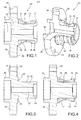
Figure 1 is a view in axial section of a hub unit with bearing rings integrated according to a typical embodiment of this invention; -
Figure 2 is a partially sectioned perspective view of the unit ofFigure 1 ; -
Figure 3 is a view in axial section of the hub unit ofFigure 2 during an intermediate phase of the manufacturing process; and -
Figure 4 is a view in axial section of the hub unit ofFigure 2 in a phase of the manufacturing process subsequent to that ofFigure 3 . - Referring initially to
Figures 1 and 2 , thenumber 10 indicates as a whole a lightweight hub unit with integrated bearing rings, for a hub bearing assembly of a motor vehicle wheel. Theunit 10 defines a central rotation axis x and is designed to rotatably mount a wheel (not shown) of a motor vehicle around the x axis. The hub bearing assembly is not shown here in its entirety. As is known, a hub bearing assembly also includes a stationary outer ring, which is connected in use to an upright of the vehicle suspension (not shown). The hub bearing assembly, of which thehub unit 10 is intended to be part, is a hub bearing assembly of the type having a double-row of rolling-contact elements interposed between the respective inner and outer raceways. For this purpose, thehub unit 10 has two radially inner raceways, indicated by 11, 12, axially spaced one away from the other. - Throughout this description and in the claims, the terms and expressions indicating positions and directions such as for example "radial", "axial", "transverse", are to be understood as referring to the x rotation axis. Expressions such as "axially inner" (or "inboard") and "axially outer" (or "outboard"), on the other hand, refer to the condition mounted on the vehicle.
- The
unit 10 comprises aninner hub 20 made of an aluminium alloy for plastic processing, preferably an aluminium alloy of the assembly (series) 6000 for the reasons described later: - The
hub 20 forms, in a single piece (Figure 3 ), acylindrical portion 21 which extends in an axial direction, and aflange 22 which extends in a radially outer direction from the axiallyouter end 23 of thecylindrical portion 21. - The
flange 22 serves to mount a wheel (not shown) of the vehicle. Four/fiveaxial holes 24 can be formed in the flange in angularly equidistant positions around the x axis. Theholes 24 are suitable to accommodate a corresponding plurality of fixing elements (not shown), for example screws for fixing the wheel. The flange has an axially innerradial surface 25, designed to be directed toward the vehicle while in use, and an axially outerradial face 26, forming a flat support surface for a brake rotor (not shown) and/or for the wheel of the vehicle. - The
cylindrical portion 21 serves to support two radiallyinner bearing rings cylindrical portion 21 has a tubular shape, and includes, in this example, an axially extending innercylindrical cavity 27. In this particular illustrated embodiment, theinner cavity 27 passes through the whole body. In other embodiments, depending on the type of wheel to be fitted (e.g. driving or driven), thecavity 27 can be closed. In still other embodiments, thecylindrical portion 21 may be filled internally, i.e. without acavity 27. - An axially tubular inner end of the
cylindrical portion 21 is indicated by 28. Thecylindrical portion 21 has a radially outercylindrical surface 30. Thehub 20 can also form an axialtubular tailpiece 29 protruding from the axially outer side, to facilitate the centring of the wheel. - The
hub 20 as shown schematically inFigure 3 is obtained by a forging process, either hot or cold, followed by a possible further machining. Once the desired shape is obtained, the hub can undergo a thermal cycle, preferably a T6 thermal cycle, to improve the mechanical properties of the material in aluminium alloy. -
Numerals Figure 4 the first and the second bearing ring which respectively have the corresponding radiallyinner raceways 12, 13 for two rows of rolling-contact elements (for example balls or tapered rollers, not shown). Bearing rings 14, 15 are then placed on the outercylindrical surface 30 of the cylindrical portion of the hub, bringing the first axially outerinner ring 15 in abutment against the axially inner surface orside 25 of theflange 22. Preferably, in order to further enhance the circumferential locking of the bearing rings 14 and 15 on the hub, the bearing rings are mounted with radial interference on the outercylindrical surface 30 of thecylindrical portion 21 of the hub. In this condition (Figure 4 ), the axially innertubular end 28 protrudes axially, at least partially, over a radial surface or endface 16 presented by the second ring being axially innermost 14 facing in an axially inner direction. - The
tubular end 28 of the hub then undergoes a cold deformation by orbital roll forming, in a radially outer direction, thus obtaining a rolled, plasticallydeformed edge 17, which axially locks both bearingrings Figures 1 and 2 ). - Those skilled in the art will recognise that the roll forming operation is actually carried out after a series of steps that are here omitted and not shown since they are unnecessary for understanding the invention. It will suffice to mention here that prior to the orbital roll forming, it is necessary to preliminarily position a row of rolling-contact elements on the axially outer side or outboard side, around the first
inner ring 14, then apply a radially outer bearing ring, then insert a row of rolling-contact elements from the axially inner side or inboard side. Thereafter it is possible to apply the secondinner ring 15 and to finally perform the orbital roll forming. - Due to the rolled
edge 17, the bearing rings 14, 15 remain firmly locked on thehub 20 both axially and circumferentially and rotationally. - The choice to build the
hub 20 in an aluminium alloy for plastic processing causes the outer surface of the rollededge 17 not to become porous, and therefore the rollededge 15 not to be subject to corrosion, particularly to so-called crack corrosion. - The alloys of the group 6000 are alloys of aluminium, silicon and magnesium, also known under the trade name Anticorodal, which have an excellent workability with the machine tools and can undergo a thermal hardening treatment (T6 treatment or by precipitation), keeping however a residual extension or ductility capacity not lower than 11-12 % after the treatment. This feature advantageously allows to obtain a durable rolled edge. Examples of particularly preferred alloys include the following alloys: 6061; 6082.
- It can be considered that the roll forming of an edge in aluminium alloy requires a much lower force than that required for roll forming a traditional steel edge. The axial force applied during the roll forming phase can be calibrated in such a way as to take into account the fact that, due to the greater thermal expansion of the aluminium alloy compared to steel, the preload in axial direction exerted by the
edge 17 against theinner rings - The hub made of aluminium alloy has advantages in terms of weight, emissions and energy consumption. Complex shape combinations as for hub composites made of aluminium with a tubular steel insert are not required.
- It is understood that the invention is not limited to the embodiments described and illustrated here, which are to be considered as examples of the unit; those skilled in the art will understand that it is possible to make various changes as regards shape, sizes, constructive and functional details and configuration of the elements described in the exemplary embodiment, without going beyond the scope of the invention as defined in the appended claims and their equivalents.
Claims (8)
- A hub unit with integrated bearing rings, the unit (10) comprising:a hub (20) forming, in a single piece:a cylindrical portion (21) extending in an axial direction,a flange (22) extending radially outwardly from an axially outer end (23) of the cylindrical portion (21), anda first (15) and a second (14) bearing ring mounted axially aligned around the cylindrical portion (21), wherein the second bearing ring (14) is axially inner with respect to the first bearing ring and provides an end face (16) facing an axially inner direction;the cylindrical portion (21) forming an axially inner end edge (17) plastically deformed in a radially outer direction against the end face (16) of the second bearing ring (14);characterized in that the hub (20) is made of a wrought aluminum alloy.
- A unit according to claim 1, characterized in that the aluminum alloy is an alloy of the 6000 series.
- A unit according to claim 2, characterized in that the aluminum alloy is an alloy selected from the group comprising the following alloys: 6061; 6082.
- A method of manufacturing a hub with integrated bearing rings, the method comprising the steps of:a) forging a hub (20) in a single piece of wrought aluminum alloy, the hub forming:a cylindrical portion (21) extending in an axial direction and providing an axially inner tubular end (28), anda flange (22) extending radially outwardly from an axially outer end (23) of the cylindrical portion (21), andb) subjecting the forged hub (20) to a hardening heat treatment;c) fitting a first (15) and a second (14) bearing ring axially aligned around the cylindrical portion (21) of the hub, so that the second ring (14) is axially inner and provides an end face (16) facing an axially inner direction, and the tubular end (28) of the axially inner cylindrical portion (21) protrudes at least partially beyond the end face (16) of the second bearing ring;d) plastically deforming the tubular end (28) in a radially outer direction against the end face (16) of the second bearing ring (14), so as to form a plastically deformed edge (17) which locks and axially preloads the first and second bearing rings (15, 14) towards the flange (22) of the hub.
- A method according to claim 4, wherein step b) includes a T6 heat treatment.
- A method according to claim 4, wherein step b) includes a precipitation hardening step.
- A method according to any one of claims 4 to 6, wherein the cylindrical portion (21) of the hub has a radially outer cylindrical surface (30), and wherein in step c) the bearing rings (14, 15) are mounted with radial interference on the outer cylindrical surface (30) of the cylindrical portion (21) of the hub.
- A hub bearing unit for a motor vehicle wheel, comprising a hub with integrated bearing rings according to any one of the preceding claims.
Applications Claiming Priority (1)
| Application Number | Priority Date | Filing Date | Title |
|---|---|---|---|
| IT000023A ITTO20130023A1 (en) | 2013-01-11 | 2013-01-11 | LIGHT WEIGHT HUB UNIT WITH INTEGRATED BEARING RINGS, AND PROCEDURE FOR ITS MANUFACTURING |
Publications (2)
| Publication Number | Publication Date |
|---|---|
| EP2754564A1 true EP2754564A1 (en) | 2014-07-16 |
| EP2754564B1 EP2754564B1 (en) | 2026-04-29 |
Family
ID=47790369
Family Applications (1)
| Application Number | Title | Priority Date | Filing Date |
|---|---|---|---|
| EP14150019.9A Active EP2754564B1 (en) | 2013-01-11 | 2014-01-02 | Lightweight hub unit with integrated bearing rings and process for its manufacture |
Country Status (5)
| Country | Link |
|---|---|
| US (1) | US9511628B2 (en) |
| EP (1) | EP2754564B1 (en) |
| KR (1) | KR20140091471A (en) |
| CN (1) | CN103921620B (en) |
| IT (1) | ITTO20130023A1 (en) |
Cited By (1)
| Publication number | Priority date | Publication date | Assignee | Title |
|---|---|---|---|---|
| EP2871067A1 (en) * | 2013-11-07 | 2015-05-13 | Aktiebolaget SKF | Bearing-hub assembly with a light alloy hub |
Families Citing this family (6)
| Publication number | Priority date | Publication date | Assignee | Title |
|---|---|---|---|---|
| ITTO20130027A1 (en) * | 2013-01-11 | 2014-07-12 | Skf Ab | UNIT OF LIGHT WEIGHT HUB WITH INTEGRATED BEARING RINGS, AND PROCEDURES FOR ITS MANUFACTURING |
| ITTO20130023A1 (en) * | 2013-01-11 | 2014-07-12 | Skf Ab | LIGHT WEIGHT HUB UNIT WITH INTEGRATED BEARING RINGS, AND PROCEDURE FOR ITS MANUFACTURING |
| JP6750513B2 (en) * | 2017-01-18 | 2020-09-02 | 日本製鉄株式会社 | Hub and manufacturing method thereof |
| JP6604484B2 (en) * | 2017-03-07 | 2019-11-13 | トヨタ自動車株式会社 | Wheel mounting structure |
| CN107554192A (en) * | 2017-09-30 | 2018-01-09 | 苏州瑞宣达金属制品有限公司 | A kind of automotive hub |
| KR102193625B1 (en) * | 2019-12-10 | 2020-12-21 | 주식회사 진흥주물 | Integral core for casting common wheel hubs |
Citations (4)
| Publication number | Priority date | Publication date | Assignee | Title |
|---|---|---|---|---|
| WO2008147284A1 (en) | 2007-06-01 | 2008-12-04 | Aktiebolaget Skf | A bearing component for a rolling bearing or for a sliding bearing |
| WO2009008152A1 (en) * | 2007-07-09 | 2009-01-15 | Ntn Corporation | Bearing device for wheel |
| DE102008034593A1 (en) * | 2008-07-25 | 2010-01-28 | Bpw Bergische Achsen Kg | Hub for rotary bearing of vehicle wheel of motor truck-axle or motor truck-trailer axle, has bearing seat for supporting roll bearing of torque proof axle and flange section arranged with opening for screw bolt on large diameter |
| WO2010063299A1 (en) * | 2008-12-02 | 2010-06-10 | Ab Skf | Bearing unit |
Family Cites Families (64)
| Publication number | Priority date | Publication date | Assignee | Title |
|---|---|---|---|---|
| GB190917142A (en) * | 1909-07-23 | 1910-05-05 | George Walter Dawes | Improvements in, and in the Manufacture of, Hubs for Cycle and other Wheels. |
| FR2490157A1 (en) * | 1980-09-17 | 1982-03-19 | Glaenzer Spicer Sa | HUB ASSEMBLY FOR MOTOR VEHICLE DRIVE WHEEL |
| CH682813A5 (en) * | 1990-02-21 | 1993-11-30 | Fischer Ag Georg | Wheel bearings. |
| DE19501268A1 (en) * | 1995-01-18 | 1996-07-25 | Teves Metallwaren Alfred | Device for measuring rotary movements |
| DE19528872A1 (en) * | 1995-08-05 | 1997-02-06 | Fag Automobiltechnik Ag | Wheel bearings |
| DE19537808C2 (en) * | 1995-10-11 | 2002-04-25 | Fag Automobiltechnik Ag | Wheel bearing |
| DE19543436C2 (en) * | 1995-11-22 | 2000-10-12 | Fag Automobiltechnik Ag | Wheel bearings |
| IT1285306B1 (en) * | 1996-03-08 | 1998-06-03 | Skf Ind Spa | METHOD OF MOUNTING THE BEARING OF A MOTOR VEHICLE WHEEL HUB ON THE RELEVANT POST AND BEARING-POST SYSTEM |
| JPH10217001A (en) * | 1997-02-04 | 1998-08-18 | Koyo Seiko Co Ltd | Machining method for hub unit shaft |
| IT1292328B1 (en) * | 1997-05-23 | 1999-01-29 | Skf Ind Spa | PROCEDURE FOR THE ASSEMBLY OF A BEARING-HUB ASSEMBLY IN THE POST OF THE SUSPENSION OF A MOTOR VEHICLE. |
| GB9713343D0 (en) * | 1997-06-24 | 1997-08-27 | Timken Co | Process and machine for uniting rotatable machine components |
| US5984422A (en) * | 1997-07-31 | 1999-11-16 | Bosch Braking Systems | Inboard mounted wheel end disconnect unit |
| DE19742027C2 (en) * | 1997-09-24 | 2001-08-30 | Fischer Georg Fahrzeugtech | Wheel bearings for motor vehicle wheels |
| DE19744552B4 (en) * | 1997-10-09 | 2007-10-11 | Continental Teves Ag & Co. Ohg | Device for supporting a wheel |
| JP3622103B2 (en) * | 1997-12-16 | 2005-02-23 | 光洋精工株式会社 | Method for assembling wheel bearing device |
| US6464399B1 (en) * | 1999-12-27 | 2002-10-15 | The Timken Company | Hub assembly for automotive vehicles |
| DE60116504T2 (en) * | 2000-09-29 | 2006-07-13 | Nsk Ltd. | BEARING UNIT FOR WHEEL DRIVE |
| JP4318205B2 (en) * | 2003-06-23 | 2009-08-19 | Ntn株式会社 | Rolling bearing for wheel and bearing device for semi-floating wheel provided with the same |
| DE10338172B3 (en) * | 2003-08-20 | 2005-06-23 | Gkn Driveline Deutschland Gmbh | Hub universal joint assembly |
| DE102004009202B4 (en) * | 2004-02-25 | 2012-09-13 | Schaeffler Technologies Gmbh & Co. Kg | wheel bearing unit |
| JP3974115B2 (en) * | 2004-03-10 | 2007-09-12 | Ntn株式会社 | Wheel bearing device |
| US20070217728A1 (en) * | 2004-09-30 | 2007-09-20 | Shinichirou Kashiwagi | Hub Unit, Rolling Bearing Assembly and Manufacture Method Thereof, as Well as Assembling Apparatus for Rolling Bearing Assebly and Assebly Method Thereof |
| JP2006138403A (en) * | 2004-11-12 | 2006-06-01 | Honda Motor Co Ltd | Wheel bearing device |
| DE102004054908B4 (en) * | 2004-11-12 | 2016-02-25 | Gkn Driveline Deutschland Gmbh | Joint outer part of a constant velocity joint for a hub-joint unit |
| EP1705391B1 (en) * | 2005-03-24 | 2008-05-14 | Aktiebolaget SKF | A hub-bearing unit for the wheel of a motor vehicle |
| US7416261B2 (en) * | 2005-03-31 | 2008-08-26 | Hiper Technology Inc. | Quick change adjustable track center front hub assembly and method of use |
| JP3923986B2 (en) * | 2005-05-10 | 2007-06-06 | Ntn株式会社 | Wheel bearing device |
| SE528876C2 (en) * | 2005-07-06 | 2007-03-06 | Skf Ab | A wheel hub and method for mounting such a wheel hub |
| WO2007010772A1 (en) * | 2005-07-20 | 2007-01-25 | Ntn Corporation | Bearing device for wheel |
| JP2007024273A (en) * | 2005-07-20 | 2007-02-01 | Ntn Corp | Manufacturing method of wheel bearing device |
| DE102006047014B4 (en) * | 2005-10-04 | 2023-01-19 | Ntn Corp. | wheel bearing device |
| JP4952021B2 (en) * | 2006-03-30 | 2012-06-13 | 株式会社ジェイテクト | Hub unit mounting structure |
| JP2007270960A (en) * | 2006-03-31 | 2007-10-18 | Jtekt Corp | Wheel bearing device |
| JP5422868B2 (en) * | 2006-08-14 | 2014-02-19 | 株式会社ジェイテクト | Axle bearing device |
| DE102006054497B4 (en) * | 2006-11-18 | 2015-03-05 | Schaeffler Technologies Gmbh & Co. Kg | Double row wheel bearing unit |
| US20080144985A1 (en) * | 2006-12-15 | 2008-06-19 | The Timken Company | Wheel End With Monitoring Capabilities |
| JP2008207589A (en) * | 2007-02-23 | 2008-09-11 | Ntn Corp | Bearing device for wheel and its manufacturing method |
| US9404531B2 (en) * | 2007-02-23 | 2016-08-02 | Ntn Corporation | Bearing apparatus for wheel |
| CN101675259B (en) * | 2007-04-04 | 2011-12-28 | Ntn株式会社 | Bearing for wheel and bearing device for wheel having same |
| JP2009036321A (en) * | 2007-08-02 | 2009-02-19 | Jtekt Corp | Axle bearing device |
| DE112008002486B4 (en) * | 2007-09-12 | 2018-10-11 | Ntn Corp. | Storage device for wheel and axle module |
| WO2009078337A1 (en) * | 2007-12-17 | 2009-06-25 | Ntn Corporation | Double-row angular bearing, bearing device for wheel, method of producing outer ring, and method of producing inner ring |
| JP2009173099A (en) * | 2008-01-23 | 2009-08-06 | Ntn Corp | Bearing device for wheel |
| DE102008009283B4 (en) * | 2008-02-15 | 2021-07-29 | Schaeffler Technologies AG & Co. KG | Wheel bearing device for a motor vehicle |
| WO2009123254A1 (en) * | 2008-04-04 | 2009-10-08 | Ntn株式会社 | Wheel bearing apparatus and axle module |
| WO2009125657A1 (en) * | 2008-04-10 | 2009-10-15 | Ntn株式会社 | Bearing device for wheel |
| JP5515246B2 (en) * | 2008-07-08 | 2014-06-11 | 株式会社ジェイテクト | Axle bearing device |
| DE102008044136A1 (en) * | 2008-11-27 | 2010-06-10 | Zf Friedrichshafen Ag | Wheel carrier of a motor vehicle |
| JP5366665B2 (en) * | 2009-06-03 | 2013-12-11 | Ntn株式会社 | Wheel bearing device |
| DE102009027078B4 (en) * | 2009-06-22 | 2015-07-16 | Saf-Holland Gmbh | Wheel bearing for vehicle axles |
| WO2011035233A1 (en) * | 2009-09-21 | 2011-03-24 | Diversified Machine Inc. | Wheel bearing retainer |
| CN103025454B (en) * | 2010-05-28 | 2015-07-29 | Skf公司 | Assembly including radial intermediate joint and corresponding method of joining two parts |
| JP2012001010A (en) * | 2010-06-14 | 2012-01-05 | Ntn Corp | Bearing device for wheel |
| CN101880844A (en) * | 2010-06-23 | 2010-11-10 | 广州金邦有色合金有限公司 | A kind of heat treatment process of ZL101A aluminum alloy for automobile hub |
| CN103402788B (en) * | 2011-03-04 | 2016-05-04 | 株式会社日进轴承 | Wheel bearing assembly |
| JP2012197932A (en) * | 2011-03-07 | 2012-10-18 | Jtekt Corp | Manufacturing method for wheel roller bearing device |
| CN102758115A (en) * | 2011-04-25 | 2012-10-31 | 蔡家源 | Manufacturing method for lightweight aluminum-based composite material hub |
| US20130257005A1 (en) * | 2012-03-27 | 2013-10-03 | The Timken Company | Compact wheel end with coupler |
| US9636946B2 (en) * | 2012-04-06 | 2017-05-02 | Il Jin Global Co., Ltd | Structure and method for coupling wheel bearings |
| CN102660716B (en) * | 2012-05-02 | 2013-09-04 | 哈尔滨工业大学 | Preparation method of nanoparticle-reinforced Al-Fe-Cr-Ti-Re heat-resistant aluminum alloy sheet |
| JP6253909B2 (en) * | 2012-10-30 | 2017-12-27 | Ntn株式会社 | Wheel bearing device |
| JP6082588B2 (en) * | 2012-12-20 | 2017-02-15 | 株式会社ジェイテクト | Vehicle bearing device |
| ITTO20130023A1 (en) * | 2013-01-11 | 2014-07-12 | Skf Ab | LIGHT WEIGHT HUB UNIT WITH INTEGRATED BEARING RINGS, AND PROCEDURE FOR ITS MANUFACTURING |
| ITTO20130027A1 (en) * | 2013-01-11 | 2014-07-12 | Skf Ab | UNIT OF LIGHT WEIGHT HUB WITH INTEGRATED BEARING RINGS, AND PROCEDURES FOR ITS MANUFACTURING |
-
2013
- 2013-01-11 IT IT000023A patent/ITTO20130023A1/en unknown
-
2014
- 2014-01-02 EP EP14150019.9A patent/EP2754564B1/en active Active
- 2014-01-06 KR KR20140001139A patent/KR20140091471A/en not_active Withdrawn
- 2014-01-13 CN CN201410071454.8A patent/CN103921620B/en active Active
- 2014-01-13 US US14/154,079 patent/US9511628B2/en active Active
Patent Citations (4)
| Publication number | Priority date | Publication date | Assignee | Title |
|---|---|---|---|---|
| WO2008147284A1 (en) | 2007-06-01 | 2008-12-04 | Aktiebolaget Skf | A bearing component for a rolling bearing or for a sliding bearing |
| WO2009008152A1 (en) * | 2007-07-09 | 2009-01-15 | Ntn Corporation | Bearing device for wheel |
| DE102008034593A1 (en) * | 2008-07-25 | 2010-01-28 | Bpw Bergische Achsen Kg | Hub for rotary bearing of vehicle wheel of motor truck-axle or motor truck-trailer axle, has bearing seat for supporting roll bearing of torque proof axle and flange section arranged with opening for screw bolt on large diameter |
| WO2010063299A1 (en) * | 2008-12-02 | 2010-06-10 | Ab Skf | Bearing unit |
Cited By (1)
| Publication number | Priority date | Publication date | Assignee | Title |
|---|---|---|---|---|
| EP2871067A1 (en) * | 2013-11-07 | 2015-05-13 | Aktiebolaget SKF | Bearing-hub assembly with a light alloy hub |
Also Published As
| Publication number | Publication date |
|---|---|
| ITTO20130023A1 (en) | 2014-07-12 |
| CN103921620A (en) | 2014-07-16 |
| EP2754564B1 (en) | 2026-04-29 |
| US20140197677A1 (en) | 2014-07-17 |
| KR20140091471A (en) | 2014-07-21 |
| CN103921620B (en) | 2018-01-26 |
| US9511628B2 (en) | 2016-12-06 |
Similar Documents
| Publication | Publication Date | Title |
|---|---|---|
| EP2754564B1 (en) | Lightweight hub unit with integrated bearing rings and process for its manufacture | |
| EP2754565B1 (en) | Lightweight hub unit with integrated bearing rings and processes for its manufacture | |
| EP2599642A1 (en) | Bearing unit | |
| CN101500823B (en) | Raceway ring member for bearing unit, bearing unit, and method and device for producing raceway ring member for bearing unit | |
| JP2014077527A (en) | Wheel bearing device and manufacturing method thereof | |
| KR20140091469A (en) | Lightweight hub bearing assembly and methods of assembling it | |
| EP2839899B1 (en) | Wheel bearing device and manufacturing method therefor | |
| US8568037B2 (en) | Flanged bearing ring for the hub of a motor vehicle wheel | |
| JP2013023086A (en) | Hub unit for supporting wheel, and method for manufacturing the same | |
| JP2012197070A (en) | Manufacturing method for wheel rolling bearing device, and wheel rolling bearing device | |
| JP5050446B2 (en) | Bearing unit | |
| JP5168852B2 (en) | Bearing unit | |
| CN104632903A (en) | Bearing-hub assembly with a light alloy hub | |
| US8579515B2 (en) | Form-coupling arrangement in a bearing ring for a motor vehicle wheel | |
| JP2010013039A (en) | Rolling bearing unit for wheel support and method of manufacturing the same | |
| EP2684709A1 (en) | Shaft member for rolling bearing device for wheel | |
| JP2012192818A (en) | Bearing device for wheel | |
| JP2012228697A (en) | Shaft member of rolling bearing device for wheel, and method for manufacturing the same | |
| JP4998980B2 (en) | Wheel bearing device | |
| JP2014008510A (en) | Method of manufacturing wheel bearing device, and wheel bearing device | |
| JP5236097B2 (en) | Wheel bearing device | |
| JP2012184813A (en) | Shaft member of rolling bearing for wheel and method for manufacturing the same | |
| JP2012183935A (en) | Shaft member of rolling bearing device for wheel | |
| JP2008051165A (en) | Bearing device for wheel | |
| JP2012183934A (en) | Shaft member of rolling bearing device for wheel |
Legal Events
| Date | Code | Title | Description |
|---|---|---|---|
| PUAI | Public reference made under article 153(3) epc to a published international application that has entered the european phase |
Free format text: ORIGINAL CODE: 0009012 |
|
| 17P | Request for examination filed |
Effective date: 20140102 |
|
| AK | Designated contracting states |
Kind code of ref document: A1 Designated state(s): AL AT BE BG CH CY CZ DE DK EE ES FI FR GB GR HR HU IE IS IT LI LT LU LV MC MK MT NL NO PL PT RO RS SE SI SK SM TR |
|
| AX | Request for extension of the european patent |
Extension state: BA ME |
|
| R17P | Request for examination filed (corrected) |
Effective date: 20150120 |
|
| RBV | Designated contracting states (corrected) |
Designated state(s): AL AT BE BG CH CY CZ DE DK EE ES FI FR GB GR HR HU IE IS IT LI LT LU LV MC MK MT NL NO PL PT RO RS SE SI SK SM TR |
|
| STAA | Information on the status of an ep patent application or granted ep patent |
Free format text: STATUS: EXAMINATION IS IN PROGRESS |
|
| 17Q | First examination report despatched |
Effective date: 20190527 |
|
| GRAP | Despatch of communication of intention to grant a patent |
Free format text: ORIGINAL CODE: EPIDOSNIGR1 |
|
| STAA | Information on the status of an ep patent application or granted ep patent |
Free format text: STATUS: GRANT OF PATENT IS INTENDED |
|
| INTG | Intention to grant announced |
Effective date: 20260212 |
|
| GRAS | Grant fee paid |
Free format text: ORIGINAL CODE: EPIDOSNIGR3 |
|
| GRAA | (expected) grant |
Free format text: ORIGINAL CODE: 0009210 |
|
| STAA | Information on the status of an ep patent application or granted ep patent |
Free format text: STATUS: THE PATENT HAS BEEN GRANTED |
|
| AK | Designated contracting states |
Kind code of ref document: B1 Designated state(s): AL AT BE BG CH CY CZ DE DK EE ES FI FR GB GR HR HU IE IS IT LI LT LU LV MC MK MT NL NO PL PT RO RS SE SI SK SM TR |
|
| REG | Reference to a national code |
Ref country code: CH Ref legal event code: F10 Free format text: ST27 STATUS EVENT CODE: U-0-0-F10-F00 (AS PROVIDED BY THE NATIONAL OFFICE) Effective date: 20260429 Ref country code: GB Ref legal event code: FG4D |
|
| P01 | Opt-out of the competence of the unified patent court (upc) registered |
Free format text: CASE NUMBER: UPC_APP_0011728_2754564/2026 Effective date: 20260401 |
|
| REG | Reference to a national code |
Ref country code: DE Ref legal event code: R096 Ref document number: 602014092996 Country of ref document: DE |
|
| REG | Reference to a national code |
Ref country code: IE Ref legal event code: FG4D |