EP2754509B1 - Press forming method and press forming device - Google Patents
Press forming method and press forming device Download PDFInfo
- Publication number
- EP2754509B1 EP2754509B1 EP12830768.3A EP12830768A EP2754509B1 EP 2754509 B1 EP2754509 B1 EP 2754509B1 EP 12830768 A EP12830768 A EP 12830768A EP 2754509 B1 EP2754509 B1 EP 2754509B1
- Authority
- EP
- European Patent Office
- Prior art keywords
- shaped workpiece
- punch
- sheet shaped
- die
- press
- Prior art date
- Legal status (The legal status is an assumption and is not a legal conclusion. Google has not performed a legal analysis and makes no representation as to the accuracy of the status listed.)
- Not-in-force
Links
Images







Classifications
-
- B—PERFORMING OPERATIONS; TRANSPORTING
- B21—MECHANICAL METAL-WORKING WITHOUT ESSENTIALLY REMOVING MATERIAL; PUNCHING METAL
- B21D—WORKING OR PROCESSING OF SHEET METAL OR METAL TUBES, RODS OR PROFILES WITHOUT ESSENTIALLY REMOVING MATERIAL; PUNCHING METAL
- B21D24/00—Special deep-drawing arrangements in, or in connection with, presses
- B21D24/04—Blank holders; Mounting means therefor
-
- B—PERFORMING OPERATIONS; TRANSPORTING
- B21—MECHANICAL METAL-WORKING WITHOUT ESSENTIALLY REMOVING MATERIAL; PUNCHING METAL
- B21D—WORKING OR PROCESSING OF SHEET METAL OR METAL TUBES, RODS OR PROFILES WITHOUT ESSENTIALLY REMOVING MATERIAL; PUNCHING METAL
- B21D22/00—Shaping without cutting, by stamping, spinning, or deep-drawing
- B21D22/20—Deep-drawing
- B21D22/22—Deep-drawing with devices for holding the edge of the blanks
Definitions
- the present invention relates to a press forming method and a press forming device for producing a press stamping product for which a high tensile stiffness is required, for example, a body panel of an automobile.
- a drawing press forming method which is called a stretch-draw process is widely used.
- This drawing press forming method is carried out as shown for example in Figure 12 such that a peripheral part of a sheet shaped workpiece P1 is gripped and constrained between an outer peripheral sandwiching part 82 of a die 81 secured to a ram 80 and a blank holder 84 elastically supported by a cushion pin 83, and the sheet shaped workpiece P1 as constrained is pressed between the die 81 and a punch 86 secured to a base 85 while being drawn by tension from the peripheral side thereof, thereby obtaining a press stamping product having a desired shape.
- the blank holder 84 is made up of a ring-shaped integrated body surrounding the punch 86. Moreover, although the figure indicates that the die 81 is movable and located on the upper side, there may be a configuration in which up-and-down relationship is reversed, or a configuration in which the punch 86 is movable.
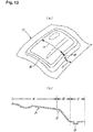
- the press stamping product P obtained by such a drawing press forming method is generally configured, for example as schematically shown in Figure 13 , such that a product part A is surrounded by a sacrifice drawing part B and a sandwiching part C, in which the sacrifice drawing part B includes a bent part E which corresponds to a boundary portion of the forming surface 86a of the punch 86 with a peripheral edge part 86b, that is, a sloped peripheral wall part 86c (see Figure 12(a) ), and the sandwiching part C is formed with a groove shape G by concavo-convex fitting in a sandwiching surface between the outer peripheral sandwiching part 82 of the die 81 and the blank holder 84 to increase sandwiching force.
- the product part A and the sacrifice drawing part B are expanded from the product corresponding part A1 and the sacrifice drawing corresponding part B1 in the sheet shaped workpiece P1, respectively due to the elongation effect during forming, and the sandwiching part C is also expanded from the sandwiching corresponding part C1 due to the formation of the groove shape G.
- the sacrifice drawing part B and the sandwiching part C of the press stamping product P is eventually cut off and removed from the product part A, it is desirable to increase the proportion of the product corresponding portion making up the sheet shaped workpiece P1 as much as possible in the viewpoint of material yield.
- the sandwiching corresponding part C1 needs to have a fixed width to ensure constraint force during forming, it is necessary to decrease the width of the sacrifice drawing corresponding part B1 in the sheet shaped workpiece P1 to improve the material yield.
- JP2011110581 discloses a die and a method for forming an overhang in which both edge parts of a sheet-metal workpiece slide in the separating direction to each other and in the same direction as the direction in the extended surface of a forming surface of a punch or in an inclined direction to the side of the punch. JP2011110581 specifies that it is prevented that a sharp bent part and a longitudinal wall part are formed so as to hinder the extension of the formed part on the sheet-metal workpiece. JP2011110581 further specifies that because the formed part is satisfactorily extendable, the improvement of quality is attained and energy is efficiently spent to extend the formed part.
- the present invention has its object to provide a press forming method and a press forming device which can significantly reduce the width of a sacrifice drawing corresponding part, thereby greatly improving the material yield upon producing a press stamping product such as a body panel of automobile from a sheet shaped workpiece, as well as effectively resolve strain of the shape of the punch due to actual cross-sectional length difference, thus allowing to obtain a high quality press stamping product having high tensile stiffness and surface quality due to an excellent forming stability, without producing tears and damages.
- the press forming method according to the first aspect of the present invention may optionally be as specified in claim 2.
- the press forming method according to the first aspect of the present invention may optionally be as specified in claim 3.
- the press forming device according to the second aspect of the present invention may optionally be as specified in claim 5.
- the press forming device according to the second aspect of the present invention may optionally be as specified in claim 6.
- the press forming device according to the second aspect of the present invention may optionally be as specified in claim 7.
- each blank holder 3 is displaced along a press axis direction to make the sheet shaped workpiece P1 superimposed on the forming surface 10 of the punch 11 in a process from when the sheet shaped workpiece P1 which is constrained at the peripheral part by the blank holder 3 comes into contact with a forming surface 10 of the punch 11 until when the workpiece is pressed between the punch 11 and the die 21, in this step, the sheet shaped workpiece P1 comes to fit with substantially the whole of the forming surface 10 of the punch 11 almost without decreasing the permissible amount of forming so that a three-dimensional shape of the forming surface 10 except the concave part 10a is transferred to the sheet shaped workpiece PI.
- each blank holder 3 is displaced along the press axis direction to make the press stamping product P disengaged from the forming surface 10 of the punch 11 after the end of forming, and after both the sandwiching members 3a and 3b of the blank holder 3 are detached, or the press stamping product P is taken out after the detachment, both the sandwiching members 3a and 3b are displaced inwardly to be returned to the initial position before constraining of the sheet shaped workpiece P1; the press stamping product P maintains its formed shape at the time of expansion until it is separated from the forming surface 10 of the punch 11 and is freed from the constraint by the blank holder 3... so that the deformation of the press stamping product P by both the sandwiching members 3a and 3b is prevented.
- the relative displacement along the press axis direction between the punch 11 and the blank holder 3 may be achieved by moving the punch 11 as a movable mold, or by moving the blank holder 3 as one body with the die 21 side, or separately.
- a device which has a simple configuration and can efficiently and stably produce a high quality press stamping product P having a higher dimensional accuracy and a higher tensile stiffness, the device is configured such that in a process from when the peripheral part of the sheet shaped workpiece P1 is constrained between both the sandwiching members 3a and 3b of each blank holder 3 as the die 21 approaches the punch 11, and then the sheet shaped workpiece P1 is pressed against and superimposed on a forming surface 10 of the punch 11 until when the sheet shaped workpiece P1 is pressed between the punch 11 and the die 21, each blank holder 3 is displaced in the outward direction by the outward displacement means to expand the sheet shaped workpiece P1, and as the die 21 is separated from the punch 11 after the end of forming, each blank holder 3 is displaced along with the die 21 by resilient biasing of the holder support member 4, then the second sandwiching member 3b is displaced as one body with
- each blank holder 3 since the inward displacement means of each blank holder 3 is configured such that only inwardly displacing the first sandwiching member 3a with a fluid pressure cylinder (an air cylinder 6) to return it to its initial position causes the second locking member 3b to be automatically displaced inwardly and returned to its initial position, when the die 21 makes action in the press axis direction for next press forming, the device configuration become simplified and functional compared to a case where a power mechanism for inward displacement for each of both the sandwiching members 3a and 3b is provided.
- a fluid pressure cylinder an air cylinder 6
- the blank holder 3 upon expanding the sheet shaped workpiece P1 with outward displacement means, first, the blank holder 3 is displaced in an obliquely outward direction with respect to the press axis direction, thereby allowing sufficient drawing effect to be exhibited and, besides, since the blank holder 3 is successively displaced in an orthogonal direction with respect to the press axis direction, the tension angle becomes shallow in the last stage of expansion so that the resistance to the material movement in the peripheral edge part 10b of the forming surface 10 of the punch 11 decreases, and thus internal strain of the sheet shaped workpiece P1 is effectively reduced by the facilitation of the material movement, making it possible to stably obtain a high quality press stamping product P having a higher dimensional accuracy and a high tensile stiffness.
- a press forming device relating to a first preferred embodiment of the present invention is made up of, as shown in Figure 1 , a punch-side metal mold 1 as a stationary lower mold attached to a base (not shown), a die-side metal mold 2 as a movable upper mold which is fixedly arranged on the lower surface side of a ram (not shown) to be opposed to the punch-side metal mold 1, four independent blank holders 3... which sandwich and constrain each side of a peripheral part of a rectangular sheet shaped workpiece P1, and a rectangular frame-shaped holder support member 4.
- each blank holder 3 is made up of a first sandwiching member 3 a which is held on the punch side via the holder support member 4, and a second sandwiching member 3b which is held on the die side.
- the punch-side metal mold 1 is arranged, as shown in Figure 2 as well, such that the punch 11 of which top part constitutes as the whole a convex forming surface 10 is arranged to protrude upwardly, and a horizontal deck 12 extending outwardly from the entire circumference of the base part of the punch 11 is provided.
- the forming surface 10 includes a local concave part 10a.
- the horizontal deck 12 is formed with a plurality of pin insertion holes 15... at a fixed spacing in two rows, inner and outer, along each side surface 11a of the punch 11, includes an upward protruding part 12a... at each of four corners, and is formed with a flange part 12b which connects between these upward protruding parts 12a... at an outer end edge.
- a mold abutment part 16 with a guide pin 16a is provided on the upper surface of each upward protruding part 12a of the horizontal deck 12
- a holder sliding contact part 17 having a rectangular convex shape is included in each of the side surfaces opposing to each other of the upward protruding parts 12a...
- further retainer safety pins 18 for the holder support member 4 are arranged to stand at four locations near each upward protruding part 12a in the vicinity of each flange part 12b along the longitudinal direction.
- the die-side metal mold 2 is made up of, as shown in Figure 4 , a die 21 having a rectangular shape in a plan view and configured to protrude downwardly, and a sloped deck 22 which extends outwardly from the entire circumference of the base part to be sloped slightly upwardly, in which the downward-facing forming surface 20 of the die 21 takes on a concave shape as the whole corresponding to the forming surface 10 of the punch 11, and has a local convex part 20a corresponding to the local concave part 10a on the punch 11 side.
- the die 21 includes holder opposite-contact parts 23, which each have a rectangular convex shape and to which a slide plate 5 is adhered, at a plurality of locations of each side surface 21a thereof.
- the sloped deck 22 includes a plurality of slide plates 5 adhered thereto along each side of the die 21, and has downward protruding parts 22a..., which each have a rectangular shape in a plan view, at four corners, and downward-facing flanges 22b... which each connect between the downward protruding parts 22a... are formed at outer end edges.
- a mold abutment part 24 with a pin hole 24a corresponding to the mold abutment part 16 on the punch 11 side is provided on the lower surface of each downward protruding part 22a of the sloped deck 22, and also strip-shaped holder holding parts 25 and 25, which each extend, at a position downwardly spaced apart from the sloped surface of the sloped deck 22, in parallel with the sloped surface in opposite directions, are provided in both side parts corresponding to each side of the die 21.
- the holder support member 4 is configured, as shown in Figure 3 as well, such that a flat plate part 4b horizontally extends out inwardly from a lower part of the outer frame part 4a which is thick in vertical direction, and a plurality of cushion pins 41... are arranged to protrude on the lower surface side.
- a plurality of slide plates 5 are adhered to the upper surface side of the flat plate part 4b, and a reciprocating air cylinder 6 in which a piston rod 6a is configured to protrude outwardly, is attached to a central position of each side.
- each rectangular corner portion of the outer frame part 4a is inwardly recessed in a L-shape in a plan view, and strip-shaped holder holding parts 42 which each extend out above the flat plate part 4b from the upper surface part corresponding to each side of the L-shape are provided, as well as vertical sliding contact parts 43 which each have a rectangular convex shape and to which each slide plate 5 is adhered are formed on both side surfaces which are adjacent and facing outwardly.
- the middle part of each side of the outer frame part 4a is recessed facing inwardly, and in the recessed portion, a vertically-oriented rectangular connecting plate 61 adhered to the tip end of the piston rod 6a of the air cylinder 6 protrudes upwardly.
- This holder support member 4 is disposed to be able to move up and down via the cushion pins 41... in such a fashion to surround the punch 11 on the horizontal deck 12 of the punch-side metal mold 1 by inserting the cushion pins 41... into the pin insertion holes 15... of the horizontal deck 12 of the punch-side metal mold 1, and is arranged such that each vertical sliding contact part 43 in each corner part of the rectangular shape comes into slide contact with the holder sliding contact part 17 of the upward protruding part 12a in the horizontal deck 12.
- the first sandwiching member 3a of each blank holder 3 which takes on a generally elongated bar shape, is formed with a concave groove 31a along the longitudinal direction in the upward facing sandwiching surface 30a on the inner edge side thereof; includes a plurality of engaging projections 32 and engaging pieces 33, which respectively protrude upwardly on the outside of the sandwiching surface 30a; is formed with a screwing part 34 for the air cylinder 6 of the holder support member 4, in the middle part in the longitudinal direction and facing outwardly; and is further formed with sloped sliding contact parts 35 which each form a sloped surface facing obliquely downward and vertical sliding contact parts 36 at a plurality of locations, respectively, in the inner side surface.
- each engaging projection 32 includes a sloped guiding part 32a facing obliquely upwardly on the inner end side thereof, and a vertical abutment part 32b which continues to the lower end of the sloped guiding part 32a; and each engaging projection 32 located at each end in the longitudinal direction includes a positioning pin hole 301 in the top surface thereof. It is noted that a plurality of circular projections 302 as opposite-contact stoppers against the second sandwiching member 3b are provided on the upper surface of the first sandwiching member 3a.
- Each first sandwiching member 3 a is supported to be movable in inward and outward directions on the flat plate part 4b of the holder support member 4 with both longitudinal end parts being held via the holder holding parts 42 and 42, and is configured to be displaced inwardly by the degenerating action of the air cylinder 6 by screwing the connecting plate 61 adhered to the tip end of a piston rod 6a of the air cylinder 6 to the screwing part 34 for connection.
- the sloped sliding contact part 35 and the vertical sliding contact part 36 of the first sandwiching member 3a are opposed to the sloped sliding contact part 13 and the vertical sliding contact part 14 of the punch 11, respectively.
- both the vertical sliding contact parts 36 and 14 abut each other as shown in the left half of Figure 1 , while at a raised position of the first sandwiching member 3a, the sloped sliding contact parts 35 and 13 are spaced apart. It is noted that the sloped sliding contact part 13 of the punch 11 and the sloped sliding contact part 35 of the first sandwiching member 3a are arranged to have the same slope angle.
- the second sandwiching member 3b of each blank holder 3 has a longitudinal section of a substantially inverted L-shape and takes on an elongated bar shape having a length corresponding to the first sandwiching member 3b, in which the lower end of the suspended part on the inner edge side makes up a downward facing sandwiching surface 30b, and a bead 31b along the longitudinal direction is formed in the sandwiching surface 30b.
- the second sandwiching part 3b includes an engaging convex part 37 which makes up a sloped guiding part 37b facing obliquely downwardly and a vertical abutment part 37b which continues to the upper end thereof at a plurality of locations in the longitudinal direction on the outer surface side of the suspended part, and is formed with a concave recessed part 38 in the vertical direction.
- a die opposite-contact part 39 having a rectangular convex surface shape is formed at a plurality of locations in the longitudinal direction on the inner surface side of the suspended part.
- the base part of the second sandwiching member 3b is configured to be gently sloped such that the upper surface becomes higher toward the outside, and have positioning pins 303 projected downwardly at both ends thereof.
- Reference number 304 denotes a circular projection as an opposite contact stopper against the first sandwiching member 3a
- 305 denotes a fall-preventing safety pin for the die-side metal mold 2.
- Each second sandwiching member 3b is supported to be movable in inward and outward directions with both the longitudinal end parts being held on the lower surface side of the sloped deck 22 of the die-side metal mold 2 via the holder holding parts 25 and 25.
- the upper surface side of the base part is in sliding contact with the lower surface of the sloped deck 22 via a slide plate 5, and at an inward moving limit, the die opposite-contact part 39 abuts the holder opposite-contact part 23 on the die 21 side.
- each blank holder 3 is arranged such that when the first and second sandwiching members 3a and 3b are both at the inward moving limit, the sandwiching surfaces 30a and 30a of both the sandwiching members 3a and 3b are vertically opposed to each other, and the bead 31b of the second sandwiching member 3 can be fitted into the concave groove 31a of the first sandwiching member 3a, and in such fitted situation, the vertical abutment parts 32b and 37b of both the sandwiching members 3a and 3b abut each other, the positioning pin 303 of the second sandwiching member 3 is inserted into the positioning pin hole 301 of the first sandwiching member 3a, and further the engaging piece 33 of the first sandwiching member 3a is fitted into the concave recessed part 38 of the second sandwiching member 3.
- the die 21 moves upwardly apart from the punch 11, and in a state in which the first sandwiching member 3 a and the second sandwiching member 3b of each blank holder 3 are vertically spaced apart, the sheet shaped workpiece P1 is disposed horizontally such that the peripheral part thereof is supported on the sandwiching surface 30a of each first sandwiching member 3a in the four blank holders 3.
- each first sandwiching member 31 is located at a upper limit position in the inward moving limit, and in a state in which the vertical sliding contact part 35 is in contact with the vertical sliding contact part 13 of the punch 11, the sandwiching surface 30a is disposed at a position higher than the top end of the forming surface 10 of the punch 11.
- the second sandwiching member 3b is raised as one body with the die 21 and is on standby in a state in which the sandwiching surface 30b thereof is disposed outside a position to face the sandwiching surface 30a of the first sandwiching member 3 a.
- the die-side metal mold 2 is moved down as shown by an arrow a1 so that the second sandwiching member 3b of the blank holder 3 as well moves down as one body with the die 21.
- the sloped guiding part 37a of the second sandwiching member 3b abuts the sloped guiding part 32a of the first sandwiching member 3a, and due to the slope guiding effect thereof, the second sandwiching member 3b is displaced inwardly as shown by an arrow a2.
- the peripheral part of the sheet shaped workpiece P1 is gripped between the sandwiching surfaces 30a and 30b of both the sandwiching members 3a and 3b, and the bead 31b gets meshed with the concave groove 31a so that a groove shape G is formed in the peripheral part of the sheet shaped workpiece P1.
- the constraining force is carried by a biasing resilience (cushion pad force) in the press axis direction of the cushion pin 41 supporting the first sandwiching member 3a via the holder support member 4.
- the downward moving force causes the entire blank holder 3 to move down as one body with the die 21 as shown by an arrow a3 with the vertical sliding contact part 36 being in sliding contact with the vertical sliding contact part 14 of the punch 11, and the sheet shaped workpiece P1 constrained by the blank holder 3 comes into contact with the forming surface 10 of the punch 11, and next becomes fittingly superimposed on substantially the whole of the forming surface 10 while being elongated so that a three-dimensional shape of the forming surface 10 except the concave part 10a is faithfully transferred to the sheet shaped workpiece P1.
- the sheet shaped workpiece P1 which is constrained by the blank holder 3 at the peripheral part is drawn out out outwardly to be expanded exhibiting desired drawing action, and as a result of the forming surface 20 of the die 21 which moves down coming into pressure contact with the sheet shaped workpiece P1 in a final step, the sheet shaped workpiece P1 is pressed between the punch 11 and the die 21 thereby being formed into a press stamping product P having a predetermined forming shape including a concave part.
- the first sandwiching member 3 a of the blank holder 3 is displaced obliquely downwardly as shown by an arrow a5 in such a manner of sliding outwardly via the slide plate 5 on the horizontal part 4b of the holder support member 4 while pressing down the holder support member 4 against the biasing of the cushion pin 41.
- the second sandwiching member 32 keeps on being displaced in the outward direction in one body with the first sandwiching member 31, since it is in sliding contact with the sloped deck 22 facing obliquely upwardly on the die 21 side via the slide plate 5, it will be displaced outwardly while relatively moving up as shown by an arrow a6 with respect to the die 21 which moves down.
- the air cylinder 6 is arranged to be free for expansion and contraction in the pressing process, and the piston rod 6a extends along with the outward displacement of the second sandwiching member 32.
- both the sandwiching members 3a and 3b of the blank holder 3 are detached upwardly and downwardly so that the press stamping product P lying on the first sandwiching member 3a can be taken out.
- both the sandwiching members 3a and 3b of the blank holder 3 are disposed at an outward position apart from the press forming part.
- both the sandwiching members 3 a and 3b of the blank holder 3 need to be returned to an initial position close to the press forming part to grip and constrain the peripheral part of the sheet shaped workpiece P1 at an appropriate position as a preparation for performing next press forming. Therefore, as shown in Figure 9(b) , by actuating the air cylinder 6 to contract, the first sandwiching member 3a is displaced by sliding inwardly on the holder support member 4, so as to be returned to the initial position at which the vertical sliding contact part 36 abuts the vertical sliding contact part 14 of the punch 11 side as shown in the left half of Figure 1 .
- the second sandwiching member 3b even if positioned at an outward position, as described above, while the die-side metal mold 2 downwardly moves at the start of forming, as a result of the sliding contact of the sloped guiding part 37a with the sloped guiding part 32a of the first sandwiching member 3a, the second sandwiching member 3b is automatically displaced inwardly by the slope guiding effect, returning to the initial position at which the bead 31b is accurately opposed to the concave groove 31a of the first sandwiching member 3 a.
- each blank holder 3 is displaced along the press axis direction to make the press stamping product P disengaged from the forming surface 10 of the punch 11 after the end of forming, and after both the sandwiching members 3a and 3b of the blank holder 3 are detached to take out the press stamping product P, and thereafter both the sandwiching members 3a and 3b which have been detached are displaced inwardly to be returned to the initial position before constraining of the sheet shaped workpiece P1; the press stamping product P maintains its formed shape at the time of expansion until it is separated from the forming surface 10 of the punch 11 and is freed from the constraint by the blank holder 3... so that the deformation of the press stamping product P is prevented.
- the press stamping product P cannot maintain the formed shape at the time of expansion, and will be deformed.
- the peripheral part of the sheet shaped workpiece P1 is gripped and thereby constrained between both sandwiching members 3 a and 3b of each blank holder 3, and each blank holder 3 is moved down as the die-side metal mold 2 moves down, so that first the sheet shaped workpiece P1 comes into contact with the forming surface 10 of the punch 11, and then is superimposed on the whole of the forming surface 10 so as to fit thereto while being elongated (see Figure 7 ).
- each blank holder 3 In a process in which each blank holder 3 is displaced obliquely downwardly in an outward direction, the holder support member 4 moves down as well against the biasing of the cushion pins 41..., but each blank holder 3 will be relatively displaced in the horizontal direction with respect to the holder support member 4 since the holder support member 4 is only allowed to move up and down.
- the present second embodiment as shown in Figure 10(a) , it is arranged such that in a step immediately before the die 21 comes into pressure contact with the sheet shaped workpiece P1, the holder support member 4 comes to abut the stopper 7 located on the horizontal deck 12 of the punch-side metal mold 1, thereby stopping the die 21 from moving down.
- each blank holder 3 which being displaced obliquely downwardly in an outward direction is instantaneously displaced outwardly in the horizontal direction by inertial force, and immediately thereafter, the sheet shaped workpiece P1 is press formed between the die 21 and the punch 11 associated with the stopping of the holder support member 4 as shown in Figure 10(b) .
- the blank holder 3 is displaced obliquely downwardly in an outward direction with respect to the press axis direction, thereby allowing sufficient drawing effect to be exhibited as in the case of the above described first embodiment, and besides, since the blank holder 3 is displaced outwardly and horizontally, the tension angle becomes shallow in the last stage of expansion so that the resistance to material movement in the peripheral edge part 10b of the forming surface 10 of the punch 11 decreases, and thus internal strain of the sheet shaped workpiece P1 is effectively reduced by the facilitation of the material movement, making it possible to stably obtain a high quality press stamping product P having a higher dimensional accuracy and a high tensile stiffness.
- FIG. 11 shows displacement cycles of the blank holder 3 in the above described first and second embodiments, in which lines A1 and A2 on the lower side represent the motion of the first sandwiching member 3a, and lines B1 and B2 on the upper side represent relative motion of the second sandwiching member 3b with respect to the die 21, the lines A1 and B1 corresponding to the first embodiment, and the lines A2 and B2 corresponding to the second embodiment.
- the first sandwiching member 3a moves down from an initial position S1 for standby before the constraint of the sheet shaped workpiece P1, the constrained sheet shaped workpiece P1 is displaced obliquely downwardly and outwardly from a position S2 in which the sheet shaped workpiece P1 is substantially superimposed on the forming surface of the punch 11, the die 21 moves up from a position S3 at which the die 21 comes into contact with the punch 11, and is displaced inwardly from a position S4, which is a rising limit, to return to the initial position S1, thus tracing a displacement cycle of four strokes.
- the first sandwiching member 3a moves down from the initial position S 1; is displaced obliquely downwardly and outwardly from the position S2 in the same fashion, but it is displaced horizontally and outwardly from a position S5 immediately before the die 21 comes into contact with the punch 11; moves up from a position S6 where the die 21 and the punch 11 come into contact; is displaced inwardly from the rising limit position S7, thereafter returning to the initial position S1; thus tracing a displacement cycle of 5 strokes.
- the relative displacement of the second sandwiching member 3b with respect to the die 21 will trace a linear reciprocal displacement cycle along each direction of slope between an initial position T1 for standby before the constraint of the sheet shaped workpiece P1 and an outward position T2 corresponding to the position S4 of the first sandwiching member 3 a side in the first embodiment, and between the initial position T1 and an outward position T3 corresponding to the position S7 on the first sandwiching member 3 a side in the second embodiment.
- the interval from the position S2 to the position S3 represents the expansion direction and expansion amount of the sheet shaped workpiece P1 in the process in which the first sandwiching member 3 a is displaced obliquely downwardly and outwardly in the first embodiment.
- the first sandwiching member 3a is displaced obliquely downwardly and outwardly from the position S2 as with the first embodiment, since the direction of displacement is converted to a horizontal direction from the position S5 which is before the position S3, the expansion direction of the sheet shaped workpiece P1 is changed to a gentler slope having an angle which is reduced by an angle of ⁇ as shown by the line C, and the expansion amount becomes larger than in the first embodiment.
- the height difference h1 between the positions S3 and S6 equals to the height difference h2 between the positions T2 and T3.
- an angle ⁇ 1 with respect to the press axis direction Y shown in the Figure be in a range of 20 to 70°. That is, letting the expansion direction of the sheet shaped workpiece P1 be the direction of slope within the above described angle range makes it possible to reduce the resistance to material movement near the peripheral edge part 10b of the forming surface 10 of the punch 11, thereby enhancing the degree of expansion, and allowing sufficient drawing effect to be exhibited so that it is possible to impart a good tensile stiffness to the product part A of the press stamping product P.
- the angle ⁇ 2 with respect to the direction normal to the press direction Y shown in the figure is preferably in a range of 1 to 10° with reference to the die 21.
- the angle ⁇ 2 is too small, it becomes difficult to securely prevent the motion of the second sandwiching member 3b to move toward the die 21 side during forming.
- the angle ⁇ 2 is too large, the outward component force of the press actuating force applied to the second sandwiching member 3b from the die 21 becomes excessively large, and the sandwiching force of the sheet shaped workpiece P1 by the blank holder 3 becomes insufficient.
- a power mechanism for inward displacement such as an air cylinder may be provided in each of both the sandwiching members.
- a fluid pressure cylinder including oil pressure, and a cam mechanism and crank mechanism driven by a motor, and the like may be adopted.
- both the detached sandwiching members 3a and 3b of each blank holder 3 after the end of forming are supposed to be returned to the initial position after the press stamping product P is taken out in the above described press forming example, they can also be returned to the initial position before the press stamping product is taken out in the present invention. That is, although, in a state in which both the sandwiching members 3a and 3b of the blank holder 3 are detached, the press stamping product P is placed on one of them in such a manner as being supported at the peripheral part thereof, since the peripheral part is under a non-constraint condition, even if the supporting sandwiching member returns to the initial position, only the peripheral part is deviated on the sandwiching member without resulting in deformation of the press stamping product P itself.
- the press stamping product P when both the sandwiching members 3a and 3b of each blank holder 3 are detached upwardly and downwardly after the end of forming, the press stamping product P will be placed on the first sandwiching member 3a, and even if the first sandwiching member 3a is inwardly displaced by an air cylinder 6 as is, only the groove shape G of the peripheral part of the press stamping product P will be deviated from the concave groove 31a of the first sandwiching member 3 a so that the press stamping product P may be taken out before the second sandwiching member 3b is returned to the initial position by the actuation of the die 2 side.
- the press forming method and press forming device of the present invention besides the configuration in which the punch 11 is a stationary lower mold and the die 21 is a movable upper mold as in the embodiments, it is possible to adopt other configurations such as one in which the top and bottom relationship between the punch 11 and the die 21 is reversed from that in the embodiments, one in which the punch 11 moves as a movable type, and one in which the press axis direction is oblique or sideways.
- outward displacement means for displacing the blank holder 3 outwardly departing from the press forming part it is possible to adopt, without being limited to the slope guiding scheme by the sliding contact between the sloped sliding contact parts 13 and 35 on the punch 11 side and the blank holder 3 side exemplified by the embodiments, a slope guiding system based on rolling contact between a sloped guiding part on one side and a roller on other side, a slope guiding system via a wedge-shaped slider, a displacement mechanism utilizing a cam, a crank, a guide rail, a universal joint, etc., various displacement mechanisms for converting the motion in the press direction of a movable press mold into a direction departing from the punch 11, and systems for singly displacing the blank holder 3 such as by a hydraulic cylinder, etc.
- each blank holder 3 which constrains a sheet shaped workpiece P1 is displaced along a press axis direction Y to make the sheet shaped workpiece P1 superimposed on the forming surface 10 of the punch 11, and then the blank holder 3 is displaced outwardly to make the sheet shaped workpiece P1 expanded, in which the timing for switching the displacement direction does not require much exactness. That is, the above described switching of the displacement direction may be performed in a state in which the convex shape of the punch 11 has been generally transferred to the sheet shaped workpiece P1, and the expansion may be started before the sheet shaped workpiece P1 covers the forming surface 10 of the punch 1 to the peripheral edge thereof.
- the displacement in an obliquely outward direction may be changed to multiple strokes with different oblique angles, or the displacement may be curvilinear.
- the configuration may be such that the sloped sliding contact part between the punch 1 side and the blank holder 3 (first sandwiching member 3a) side is made up of multiple stages and the slope angle with respect to the press axis direction becomes larger in the later stages.
- the sliding contact part may be made up of a curved surface.
- the blank holder 3 although four of them corresponding to each side of the press forming part having a rectangular shape in a plan view are used in the embodiments, an appropriate number, not less than 2, of holders may be adopted, for example, 3 holders when the press forming part has a generally triangular shape or circular shape in a plan view, a number corresponding to each side in the case of a polygon not less than 5 angles (pentagon), 2 holders facing each other in the width direction when an elongated sheet shaped workpiece P1 is expanded only in the width direction, depending on the shapes of press forming part and required expansion directions.
- the holder support member 4 instead of a ring-shaped unit body surrounding the outside of the punch 11 as in the embodiments, a plurality of mutually independent members corresponding to each of one or more blank holders 3 may be used.
- the sheet shaped workpiece P1 addressed in the present invention is not limited to the exemplified thin metal sheet, but includes various materials, such as sheet materials of thermoplastic resins such as polypropylene, polyvinyl chloride, polyethylene terephthalate, polyacryl, etc., fiber reinforced resin sheets such as FRP and laminated sheet materials thereof, and resin laminated metal sheets.
- thermoplastic resins such as polypropylene, polyvinyl chloride, polyethylene terephthalate, polyacryl, etc.
- fiber reinforced resin sheets such as FRP and laminated sheet materials thereof, and resin laminated metal sheets.
Landscapes
- Engineering & Computer Science (AREA)
- Mechanical Engineering (AREA)
- Shaping Metal By Deep-Drawing, Or The Like (AREA)
- Mounting, Exchange, And Manufacturing Of Dies (AREA)
Description
- The present invention relates to a press forming method and a press forming device for producing a press stamping product for which a high tensile stiffness is required, for example, a body panel of an automobile.
- Conventionally, as means of producing a press stamping product such as a body panel of an automobile from a sheet shaped workpiece made up of a thin metal sheet, a drawing press forming method which is called a stretch-draw process is widely used. This drawing press forming method is carried out as shown for example in
Figure 12 such that a peripheral part of a sheet shaped workpiece P1 is gripped and constrained between an outerperipheral sandwiching part 82 of adie 81 secured to aram 80 and ablank holder 84 elastically supported by acushion pin 83, and the sheet shaped workpiece P1 as constrained is pressed between the die 81 and apunch 86 secured to abase 85 while being drawn by tension from the peripheral side thereof, thereby obtaining a press stamping product having a desired shape. Note that theblank holder 84 is made up of a ring-shaped integrated body surrounding thepunch 86. Moreover, although the figure indicates that thedie 81 is movable and located on the upper side, there may be a configuration in which up-and-down relationship is reversed, or a configuration in which thepunch 86 is movable. - The press stamping product P obtained by such a drawing press forming method is generally configured, for example as schematically shown in
Figure 13 , such that a product part A is surrounded by a sacrifice drawing part B and a sandwiching part C, in which the sacrifice drawing part B includes a bent part E which corresponds to a boundary portion of the forming surface 86a of thepunch 86 with a peripheral edge part 86b, that is, a sloped peripheral wall part 86c (seeFigure 12(a) ), and the sandwiching part C is formed with a groove shape G by concavo-convex fitting in a sandwiching surface between the outerperipheral sandwiching part 82 of the die 81 and theblank holder 84 to increase sandwiching force. It is noted that the product part A and the sacrifice drawing part B are expanded from the product corresponding part A1 and the sacrifice drawing corresponding part B1 in the sheet shaped workpiece P1, respectively due to the elongation effect during forming, and the sandwiching part C is also expanded from the sandwiching corresponding part C1 due to the formation of the groove shape G. - Further, since the sacrifice drawing part B and the sandwiching part C of the press stamping product P is eventually cut off and removed from the product part A, it is desirable to increase the proportion of the product corresponding portion making up the sheet shaped workpiece P1 as much as possible in the viewpoint of material yield. However, since the sandwiching corresponding part C1 needs to have a fixed width to ensure constraint force during forming, it is necessary to decrease the width of the sacrifice drawing corresponding part B1 in the sheet shaped workpiece P1 to improve the material yield. On the other hand, to obtain a high quality product as the press stamping product P, it is essential to impart a high tensile stiffness thereto by enhancing the expansion of the product part A during forming.
- However, when the bending of the peripheral edge part 86b of the forming surface 86a in the
punch 86 is enhanced to decrease the angle with respect to the press axis direction of the sloped peripheral wall part 86c, the elongation at the sacrifice drawing part B increases, thereby allowing the region of the sacrifice drawing corresponding part B1 in the sheet shaped workpiece P1 to be small, but on the other hand, since the moving resistance of the material toward the peripheral side increases due to the peripheral edge part 86b having a severe bend, the expansion in the product part A becomes insufficient, thus disabling to impart high tensile stiffness thereto. Further, on the contrary, when the level of bending of the peripheral edge part 86b of the forming surface 86a is decreased, thereby increasing the angle of the sloped peripheral wall part 86c, since the moving resistance of the material in the peripheral edge part 86b having a less-severe bend decreases, it is possible to sufficiently expand the product part A thereby imparting high tensile stiffness thereto, but the region of the sacrifice drawing correspondingpart B 1 in the sheet shaped workpiece P1 must be increased, thereby resulting in a decrease of material yield. Therefore, in conventional general drawing press forming, a problem exists in that increasing the material yield and imparting high tensile stiffness to the press stamping product are mutually contradictory in a methodological sense, and cannot be achieved at the same time. - Then, as a tensile forming and tensile press forming, several methods of performing pressing are proposed in which the peripheral part of the sheet shaped workpiece is sandwiched and constrained by a blank holder, and the constrained sheet shaped workpiece is expanded beforehand by outward slide of the blank holder, and is thereafter pressed while being gripped between the punch and the die (for example,
Patent Literatures 1 to 3). According to these proposed methods, it is reported that by setting the sandwiching position of the sheet shaped workpiece by the blank holder to a position near the peripheral edge part of the forming surface of the punch, it is possible to narrow the sacrifice drawing corresponding part in the sheet shaped workpiece, thereby increasing material yield, and also impart high tensile stiffness to the press stamping product. -
JP2011110581 JP2011110581 JP2011110581 -
- Patent Literature 1: Japanese Patent Publication No.
51-1571 - Patent Literature 2: Japanese Utility Model Laid-Open No.
6-5723 - Patent Literature 3: Japanese Patent No.
3410613 - The above proposed method of pressing between a punch and a die after expanding a sheet shaped workpiece in advance has not yet been adopted for practical usages. As a causal factor for that, a critical problem exists in that since expanding the sheet shaped workpiece in advance as in the proposed method will reduce the permissible amount of forming before forming, material is not fed to regions where actual cross-sectional length is large, during forming, thereby resulting in forming defects. That is, when there are local concavo-convex parts on the forming surface of the punch, while strain is generated due to excess or deficiency of material caused by actual cross-section length difference at the concavo-convex parts and in the vicinity thereof as pressing proceeds, free movement of material is impaired by expansion before forming, and stain and residual stress increase so that it is inevitable that dimensional accuracy and surface quality deteriorate, and tears (cracks) etc. occur in portions where material becomes deficient.
- In view of the above described circumstances, the present invention has its object to provide a press forming method and a press forming device which can significantly reduce the width of a sacrifice drawing corresponding part, thereby greatly improving the material yield upon producing a press stamping product such as a body panel of automobile from a sheet shaped workpiece, as well as effectively resolve strain of the shape of the punch due to actual cross-sectional length difference, thus allowing to obtain a high quality press stamping product having high tensile stiffness and surface quality due to an excellent forming stability, without producing tears and damages.
- According to a first aspect of the present invention there is provided a press forming method according to
claim 1. - The press forming method according to the first aspect of the present invention may optionally be as specified in
claim 2. - The press forming method according to the first aspect of the present invention may optionally be as specified in
claim 3. - According to a second aspect of the present invention there is provided a press forming device according to
claim 4. - The press forming device according to the second aspect of the present invention may optionally be as specified in
claim 5. - The press forming device according to the second aspect of the present invention may optionally be as specified in
claim 6. - The press forming device according to the second aspect of the present invention may optionally be as specified in
claim 7. - Next, advantageous effects of the present invention will be described with reference to reference characters of the drawings. First, according to the press forming method relating to the invention of
claim 1, since, firstly, eachblank holder 3 is displaced along a press axis direction to make the sheet shaped workpiece P1 superimposed on the formingsurface 10 of thepunch 11 in a process from when the sheet shaped workpiece P1 which is constrained at the peripheral part by theblank holder 3 comes into contact with a formingsurface 10 of thepunch 11 until when the workpiece is pressed between thepunch 11 and thedie 21, in this step, the sheet shaped workpiece P1 comes to fit with substantially the whole of the formingsurface 10 of thepunch 11 almost without decreasing the permissible amount of forming so that a three-dimensional shape of the formingsurface 10 except the concave part 10a is transferred to the sheet shaped workpiece PI. Next, by displacing theblank holder 3 in an outward direction to expand the sheet shaped workpiece P1, it is possible to cause a smooth material movement from the middle side to the peripheral side at low resistance in the peripheral edge part 10b of the formingsurface 10. Therefore, by arranging the sandwiching position of the sheet shaped workpiece P1 by theblank holder 3 at a position close to the peripheral edge part 10b of the formingsurface 10 of thepunch 11, it is possible to significantly reduce the width of the sacrifice drawing correspondingpart B 1 in the sheet shaped workpiece P1, thereby significantly improving the material yield, and imparting high tensile stiffness to the press stamping product P, and further, even if strain due to excessive amount of material occurs in a portion having small actual cross-sectional length due to a concavity and convexity of the formingsurface 10, the excess material of the strained portion is effectively withdrawn to the peripheral side by the material movement in the expansion process, thereby getting rid of the strain. - Furthermore, since each
blank holder 3 is displaced along the press axis direction to make the press stamping product P disengaged from the formingsurface 10 of thepunch 11 after the end of forming, and after both thesandwiching members 3a and 3b of theblank holder 3 are detached, or the press stamping product P is taken out after the detachment, both thesandwiching members 3a and 3b are displaced inwardly to be returned to the initial position before constraining of the sheet shaped workpiece P1; the press stamping product P maintains its formed shape at the time of expansion until it is separated from the formingsurface 10 of thepunch 11 and is freed from the constraint by theblank holder 3... so that the deformation of the press stamping product P by both thesandwiching members 3a and 3b is prevented. Thus, the relative displacement along the press axis direction between thepunch 11 and theblank holder 3 may be achieved by moving thepunch 11 as a movable mold, or by moving theblank holder 3 as one body with thedie 21 side, or separately. - According to the preferred embodiment of the invention of
claim 2, in the above described press forming method in which the die 21 actuates, since theblank holder 3 is displaced as one body with thedie 21 along the press axis direction from when constraining the peripheral part of the sheet shaped workpiece P1 until when the sheet shaped workpiece P1 is superimposed on the formingsurface 10 of thepunch 11, and then is displaced in an outward direction by an actuating force of thedie 21, there is no need of a separate driving mechanism for the displacement of theblank holder 3, and thus it possible to configure the press forming device compactly and functionally. - According to the preferred embodiment of the invention of
claim 3, in the above described press forming method, when a sheet shaped workpiece P1 is expanded by the displacement of eachblank holder 3 in an outward direction after the plate shaped workpiece P is superimposed on the formingsurface 10 of thepunch 11, since first, theblank holder 3 is displaced in an obliquely outward direction in a specific angle range with respect to the press axis direction, thereby allowing sufficient drawing effect to be exhibited, and is further displaced in an outward direction orthogonal to the press axis direction, thereby making the tensile angle shallow, the resistance to material movement in the peripheral edge part 10b of the formingsurface 10 of thepunch 11 decreases in the last stage of expansion, and thus internal strain of the sheet shaped workpiece P1 is effectively reduced by the facilitation of the material movement, making it possible to stably obtain a high quality press stamping product P having a higher dimensional accuracy and a higher tensile stiffness. - According to the invention of
claim 4, as a device to be used for the above described press forming, a device is provided which has a simple configuration and can efficiently and stably produce a high quality press stamping product P having a higher dimensional accuracy and a higher tensile stiffness, the device is configured such that in a process from when the peripheral part of the sheet shaped workpiece P1 is constrained between both thesandwiching members 3a and 3b of eachblank holder 3 as the die 21 approaches thepunch 11, and then the sheet shaped workpiece P1 is pressed against and superimposed on a formingsurface 10 of thepunch 11 until when the sheet shaped workpiece P1 is pressed between thepunch 11 and thedie 21, eachblank holder 3 is displaced in the outward direction by the outward displacement means to expand the sheet shaped workpiece P1, and as thedie 21 is separated from thepunch 11 after the end of forming, eachblank holder 3 is displaced along with thedie 21 by resilient biasing of theholder support member 4, then thesecond sandwiching member 3b is displaced as one body with thedie 11 and is detached with respect the first sandwiching member 3 a which is stopped at a displacement limit, and both thesandwiching members 3a and 3b which have been detached are returned to an initial position by the inward displacement means. - According to the press forming device relating to the preferred embodiment of the invention of
claim 5, since the inward displacement means of eachblank holder 3 is configured such that only inwardly displacing the first sandwiching member 3a with a fluid pressure cylinder (an air cylinder 6) to return it to its initial position causes thesecond locking member 3b to be automatically displaced inwardly and returned to its initial position, when thedie 21 makes action in the press axis direction for next press forming, the device configuration become simplified and functional compared to a case where a power mechanism for inward displacement for each of both thesandwiching members 3a and 3b is provided. - According to the press forming device relating to the preferred embodiment of the invention of
claim 6, upon expanding the sheet shaped workpiece P1 with outward displacement means, first, theblank holder 3 is displaced in an obliquely outward direction with respect to the press axis direction, thereby allowing sufficient drawing effect to be exhibited and, besides, since theblank holder 3 is successively displaced in an orthogonal direction with respect to the press axis direction, the tension angle becomes shallow in the last stage of expansion so that the resistance to the material movement in the peripheral edge part 10b of the formingsurface 10 of thepunch 11 decreases, and thus internal strain of the sheet shaped workpiece P1 is effectively reduced by the facilitation of the material movement, making it possible to stably obtain a high quality press stamping product P having a higher dimensional accuracy and a high tensile stiffness. Furthermore, since the above described displacement in the obliquely outward direction is performed by a sloped guidance effect associated with sliding contact between the sloped slidingcontact parts punch 11 side, and the next displacement in the direction orthogonal to the press axis direction is performed by the inertial force associated with the stopping of the movement of theholder support member 4, the structure for producing both displacements is significantly simplified, and a high operating reliability is obtained. - According to the preferred embodiment of the invention of
claim 7, in the above described press forming device, since a far and near moving direction of thesecond sandwiching member 3b of theblank holder 3 with respect to thedie 21 side is inclined in a specific angle range with respect to the plane orthogonal to the press axis direction so as to be further spaced apart from thepunch 11 side at a larger distance, it is possible to securely inhibit the movement of thesecond sandwiching member 3b to approach the die 21 side during forming. -
- [
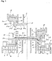
Figure 1] Figure 1 is a longitudinal sectional side view of principal parts of a press forming device before and after forming, relating to a first preferred embodiment of the present invention. - [
Figure 2] Figure 2 is a perspective view showing a longitudinal half of a punch-side metal mold of the same press forming device. - [
Figure 3] Figure 3 is a perspective view showing longitudinal halves of a holder support member, and a first sandwiching member of a blank holder of the same press forming device. - [
Figure 4] Figure 4 is a perspective view showing longitudinal halves of a die-side metal mold and a second sandwiching member of a blank holder of the same press forming device. - [
Figure 5] Figure 5 shows principal parts of the same press forming device, in which (a) is a longitudinal sectional side view showing a sheet shaped workpiece before being sandwiched and a second sandwiching member of the blank holder being located at an outward position, and (b) is a longitudinal sectional side view of the second sandwiching member as being inwardly displaced. - [
Figure 6] Figure 6 shows principal parts of the same press forming device, in which (a) is a longitudinal sectional side view showing the sheet shaped workpiece before being sandwiched and the second sandwiching member of the blank holder being inwardly displaced up to an initial position, and (b) is a longitudinal sectional side view showing a step in which the sheet shaped workpiece is sandwiched. - [
Figure 7] Figure 7 shows principal parts of the same press forming device, in which (a) and (b) are longitudinal sectional side views at positions different from each other in a step in which the workpiece is superimposed on the forming surface of the punch. - [
Figure 8] Figure 8 shows principal parts of the same press forming device, in which (a) is a longitudinal sectional side view at the end of pressing, and (b) is a longitudinal sectional side view of a step in which a press stamping product after the end of pressing is disengaged from the punch. - [
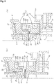
Figure 9] Figure 9 shows principal parts of the same press forming device, in which (a) is a longitudinal sectional side view showing the first sandwiching member and the second sandwiching member of the blank holder being detached after the end of pressing, and (b) is a longitudinal sectional side view showing the first sandwiching member being inwardly displaced after the end of pressing. - [
Figure 10] Figure 10 shows principal parts of a press forming device relating to a second embodiment of the present invention, in which (a) is a longitudinal sectional side view showing the blank holder being displaced in an obliquely outward direction, and (b) is a longitudinal sectional side view showing the blank holder next being displaced in a direction orthogonal to the press axis direction. - [
Figure 11] Figure 11 is a diagram showing displacement cycles of the first and second sandwiching members of the blank holder in each of the press forming devices of the first and second preferred embodiments of the present invention. - [
Figure 12] Figure 12 shows forming operation by a conventional press forming device, in which (a) is a longitudinal sectional side view before forming, and (b) is a longitudinal sectional side view after forming. - [
Figure 13] Figure 13 schematically shows an example of a press stamping product, in which (a) is a perspective view, and (b) is a longitudinal sectional view of a principal part. Description of Embodiments - Hereafter, a press forming method and a press forming device relating to the present invention will be specifically described with reference to the drawings.
- A press forming device relating to a first preferred embodiment of the present invention is made up of, as shown in
Figure 1 , a punch-side metal mold 1 as a stationary lower mold attached to a base (not shown), a die-side metal mold 2 as a movable upper mold which is fixedly arranged on the lower surface side of a ram (not shown) to be opposed to the punch-side metal mold 1, four independentblank holders 3... which sandwich and constrain each side of a peripheral part of a rectangular sheet shaped workpiece P1, and a rectangular frame-shapedholder support member 4. Moreover, eachblank holder 3 is made up of a first sandwiching member 3 a which is held on the punch side via theholder support member 4, and asecond sandwiching member 3b which is held on the die side. - The punch-
side metal mold 1 is arranged, as shown inFigure 2 as well, such that thepunch 11 of which top part constitutes as the whole a convex formingsurface 10 is arranged to protrude upwardly, and ahorizontal deck 12 extending outwardly from the entire circumference of the base part of thepunch 11 is provided. It is noted that the formingsurface 10 includes a local concave part 10a. On each side surface 11a of thepunch 11, a plurality of sloped slidingcontact parts 13 each forming a sloped surface facing obliquely upwardly, and a plurality of vertical slidingcontact parts 14 are arranged to protrude, and aslide plate 5 is adhered to the surface of each of these slidingcontact parts horizontal deck 12 is formed with a plurality of pin insertion holes 15... at a fixed spacing in two rows, inner and outer, along each side surface 11a of thepunch 11, includes an upward protruding part 12a... at each of four corners, and is formed with a flange part 12b which connects between these upward protruding parts 12a... at an outer end edge. Further, amold abutment part 16 with a guide pin 16a is provided on the upper surface of each upward protruding part 12a of thehorizontal deck 12, a holder slidingcontact part 17 having a rectangular convex shape is included in each of the side surfaces opposing to each other of the upward protruding parts 12a..., and furtherretainer safety pins 18 for theholder support member 4 are arranged to stand at four locations near each upward protruding part 12a in the vicinity of each flange part 12b along the longitudinal direction. - The die-
side metal mold 2 is made up of, as shown inFigure 4 , a die 21 having a rectangular shape in a plan view and configured to protrude downwardly, and asloped deck 22 which extends outwardly from the entire circumference of the base part to be sloped slightly upwardly, in which the downward-facing formingsurface 20 of the die 21 takes on a concave shape as the whole corresponding to the formingsurface 10 of thepunch 11, and has a local convex part 20a corresponding to the local concave part 10a on thepunch 11 side. Thedie 21 includes holder opposite-contact parts 23, which each have a rectangular convex shape and to which aslide plate 5 is adhered, at a plurality of locations of each side surface 21a thereof. On the other hand, the slopeddeck 22 includes a plurality ofslide plates 5 adhered thereto along each side of the die 21, and has downward protruding parts 22a..., which each have a rectangular shape in a plan view, at four corners, and downward-facing flanges 22b... which each connect between the downward protruding parts 22a... are formed at outer end edges. Further, amold abutment part 24 with a pin hole 24a corresponding to themold abutment part 16 on thepunch 11 side is provided on the lower surface of each downward protruding part 22a of the slopeddeck 22, and also strip-shapedholder holding parts deck 22, in parallel with the sloped surface in opposite directions, are provided in both side parts corresponding to each side of thedie 21. - The
holder support member 4 is configured, as shown inFigure 3 as well, such that aflat plate part 4b horizontally extends out inwardly from a lower part of theouter frame part 4a which is thick in vertical direction, and a plurality of cushion pins 41... are arranged to protrude on the lower surface side. A plurality ofslide plates 5 are adhered to the upper surface side of theflat plate part 4b, and areciprocating air cylinder 6 in which a piston rod 6a is configured to protrude outwardly, is attached to a central position of each side. Further, each rectangular corner portion of theouter frame part 4a is inwardly recessed in a L-shape in a plan view, and strip-shapedholder holding parts 42 which each extend out above theflat plate part 4b from the upper surface part corresponding to each side of the L-shape are provided, as well as vertical slidingcontact parts 43 which each have a rectangular convex shape and to which eachslide plate 5 is adhered are formed on both side surfaces which are adjacent and facing outwardly. Moreover, the middle part of each side of theouter frame part 4a is recessed facing inwardly, and in the recessed portion, a vertically-oriented rectangular connectingplate 61 adhered to the tip end of the piston rod 6a of theair cylinder 6 protrudes upwardly. - This
holder support member 4 is disposed to be able to move up and down via the cushion pins 41... in such a fashion to surround thepunch 11 on thehorizontal deck 12 of the punch-side metal mold 1 by inserting the cushion pins 41... into the pin insertion holes 15... of thehorizontal deck 12 of the punch-side metal mold 1, and is arranged such that each vertical slidingcontact part 43 in each corner part of the rectangular shape comes into slide contact with the holder slidingcontact part 17 of the upward protruding part 12a in thehorizontal deck 12. - As shown in
Figure 3 as well, the first sandwiching member 3a of eachblank holder 3, which takes on a generally elongated bar shape, is formed with a concave groove 31a along the longitudinal direction in the upward facing sandwiching surface 30a on the inner edge side thereof; includes a plurality of engagingprojections 32 and engagingpieces 33, which respectively protrude upwardly on the outside of the sandwiching surface 30a; is formed with a screwingpart 34 for theair cylinder 6 of theholder support member 4, in the middle part in the longitudinal direction and facing outwardly; and is further formed with sloped slidingcontact parts 35 which each form a sloped surface facing obliquely downward and vertical slidingcontact parts 36 at a plurality of locations, respectively, in the inner side surface. Thus, each engagingprojection 32 includes a sloped guiding part 32a facing obliquely upwardly on the inner end side thereof, and a vertical abutment part 32b which continues to the lower end of the sloped guiding part 32a; and each engagingprojection 32 located at each end in the longitudinal direction includes apositioning pin hole 301 in the top surface thereof. It is noted that a plurality ofcircular projections 302 as opposite-contact stoppers against thesecond sandwiching member 3b are provided on the upper surface of the first sandwiching member 3a. - Each first sandwiching member 3 a is supported to be movable in inward and outward directions on the
flat plate part 4b of theholder support member 4 with both longitudinal end parts being held via theholder holding parts air cylinder 6 by screwing the connectingplate 61 adhered to the tip end of a piston rod 6a of theair cylinder 6 to the screwingpart 34 for connection. In this supporting situation, the sloped slidingcontact part 35 and the vertical slidingcontact part 36 of the first sandwiching member 3a are opposed to the sloped slidingcontact part 13 and the vertical slidingcontact part 14 of thepunch 11, respectively. Moreover, it is arranged such that at an inward moving limit of the first sandwiching member 3 a, both the vertical slidingcontact parts Figure 1 , while at a raised position of the first sandwiching member 3a, the sloped slidingcontact parts contact part 13 of thepunch 11 and the sloped slidingcontact part 35 of the first sandwiching member 3a are arranged to have the same slope angle. - On the other hand, as shown in
Figure 4 as well, thesecond sandwiching member 3b of eachblank holder 3 has a longitudinal section of a substantially inverted L-shape and takes on an elongated bar shape having a length corresponding to thefirst sandwiching member 3b, in which the lower end of the suspended part on the inner edge side makes up a downward facingsandwiching surface 30b, and abead 31b along the longitudinal direction is formed in thesandwiching surface 30b. Further, thesecond sandwiching part 3b includes an engagingconvex part 37 which makes up a sloped guidingpart 37b facing obliquely downwardly and avertical abutment part 37b which continues to the upper end thereof at a plurality of locations in the longitudinal direction on the outer surface side of the suspended part, and is formed with a concave recessedpart 38 in the vertical direction. Further, a die opposite-contact part 39 having a rectangular convex surface shape is formed at a plurality of locations in the longitudinal direction on the inner surface side of the suspended part. Moreover, the base part of thesecond sandwiching member 3b is configured to be gently sloped such that the upper surface becomes higher toward the outside, and havepositioning pins 303 projected downwardly at both ends thereof.Reference number 304 denotes a circular projection as an opposite contact stopper against thefirst sandwiching member 3a, and 305 denotes a fall-preventing safety pin for the die-side metal mold 2. - Each
second sandwiching member 3b is supported to be movable in inward and outward directions with both the longitudinal end parts being held on the lower surface side of the slopeddeck 22 of the die-side metal mold 2 via theholder holding parts second sandwiching member 3b, the upper surface side of the base part is in sliding contact with the lower surface of the slopeddeck 22 via aslide plate 5, and at an inward moving limit, the die opposite-contact part 39 abuts the holder opposite-contact part 23 on the die 21 side. - Moreover, each
blank holder 3 is arranged such that when the first andsecond sandwiching members 3a and 3b are both at the inward moving limit, the sandwiching surfaces 30a and 30a of both thesandwiching members 3a and 3b are vertically opposed to each other, and thebead 31b of thesecond sandwiching member 3 can be fitted into the concave groove 31a of the first sandwiching member 3a, and in such fitted situation, thevertical abutment parts 32b and 37b of both thesandwiching members 3a and 3b abut each other, thepositioning pin 303 of thesecond sandwiching member 3 is inserted into thepositioning pin hole 301 of the first sandwiching member 3a, and further the engagingpiece 33 of the first sandwiching member 3a is fitted into the concave recessedpart 38 of thesecond sandwiching member 3. - To press stamp the sheet shaped workpiece P1 made of a thin metal sheet by the press forming device of the above described configuration, first, as shown in the left half in
Figure 1 , the die 21 moves upwardly apart from thepunch 11, and in a state in which the first sandwiching member 3 a and thesecond sandwiching member 3b of eachblank holder 3 are vertically spaced apart, the sheet shaped workpiece P1 is disposed horizontally such that the peripheral part thereof is supported on the sandwiching surface 30a of each first sandwiching member 3a in the fourblank holders 3. At this moment, eachfirst sandwiching member 31 is located at a upper limit position in the inward moving limit, and in a state in which the vertical slidingcontact part 35 is in contact with the vertical slidingcontact part 13 of thepunch 11, the sandwiching surface 30a is disposed at a position higher than the top end of the formingsurface 10 of thepunch 11. Moreover, thesecond sandwiching member 3b is raised as one body with thedie 21 and is on standby in a state in which thesandwiching surface 30b thereof is disposed outside a position to face the sandwiching surface 30a of the first sandwiching member 3 a. - From the above described standby state, as shown in
Figure 5(a) , the die-side metal mold 2 is moved down as shown by an arrow a1 so that thesecond sandwiching member 3b of theblank holder 3 as well moves down as one body with thedie 21. In the course of the down movement, as shown inFigure 5(b) , the sloped guiding part 37a of thesecond sandwiching member 3b abuts the sloped guiding part 32a of the first sandwiching member 3a, and due to the slope guiding effect thereof, thesecond sandwiching member 3b is displaced inwardly as shown by an arrow a2. Next, as shown inFigure 6(a) , thevertical abutment parts 32b and 37b of both thesandwiching members 3a and 3b come into contact with each other, and in this step, thepositioning pin 303 of thesecond sandwiching member 3 fits into thepositioning pin hole 301 of the first sandwiching member 3a which has become concentric therewith; and the die opposite-contact part 39 of thesecond sandwiching member 3b comes into contact with the holder opposite-contact part 23 of the die 21 side so that thesecond sandwiching member 3b is accurately positioned with respect to the first sandwiching member 3 a. - Therefore, as a result of the
second sandwiching member 3b moving down together with the die 21, the peripheral part of the sheet shaped workpiece P1 is gripped between the sandwichingsurfaces 30a and 30b of both thesandwiching members 3a and 3b, and thebead 31b gets meshed with the concave groove 31a so that a groove shape G is formed in the peripheral part of the sheet shaped workpiece P1. Thus, while the sheet shaped workpiece P1 is constrained at its peripheral part by theblank holder 3, the constraining force is carried by a biasing resilience (cushion pad force) in the press axis direction of thecushion pin 41 supporting the first sandwiching member 3a via theholder support member 4. - When the die 21 further moves down, as shown in
Figure 7(a) , the downward moving force causes the entireblank holder 3 to move down as one body with the die 21 as shown by an arrow a3 with the vertical slidingcontact part 36 being in sliding contact with the vertical slidingcontact part 14 of thepunch 11, and the sheet shaped workpiece P1 constrained by theblank holder 3 comes into contact with the formingsurface 10 of thepunch 11, and next becomes fittingly superimposed on substantially the whole of the formingsurface 10 while being elongated so that a three-dimensional shape of the formingsurface 10 except the concave part 10a is faithfully transferred to the sheet shaped workpiece P1. Then, as shown inFigure 7(b) , in a step in which the sheet shaped workpiece P1 comes to be superimposed up to the vicinity of the peripheral edge part 10b of the formingsurface 10 of thepunch 11, the sloped slidingcontact part 35 of the first sandwiching member 3a of theblank holder 3 abuts the sloped slidingcontact part 13 of thepunch 11. - Next, as the
die 21 keeps moving down, as shown inFigure 8(a) , due to the slope guiding effect by the sliding contact between the sloped slidingcontact parts blank holder 3 is displaced in the outward direction departing from the press forming part, that is, the direction of an arrow a4, while it moves down. Along with the outward displacement, the sheet shaped workpiece P1 which is constrained by theblank holder 3 at the peripheral part is drawn out outwardly to be expanded exhibiting desired drawing action, and as a result of the formingsurface 20 of the die 21 which moves down coming into pressure contact with the sheet shaped workpiece P1 in a final step, the sheet shaped workpiece P1 is pressed between thepunch 11 and the die 21 thereby being formed into a press stamping product P having a predetermined forming shape including a concave part. It is noted that in this expansion process, the first sandwiching member 3 a of theblank holder 3 is displaced obliquely downwardly as shown by an arrow a5 in such a manner of sliding outwardly via theslide plate 5 on thehorizontal part 4b of theholder support member 4 while pressing down theholder support member 4 against the biasing of thecushion pin 41. On the other hand, while thesecond sandwiching member 32 keeps on being displaced in the outward direction in one body with thefirst sandwiching member 31, since it is in sliding contact with the slopeddeck 22 facing obliquely upwardly on the die 21 side via theslide plate 5, it will be displaced outwardly while relatively moving up as shown by an arrow a6 with respect to the die 21 which moves down. Moreover, theair cylinder 6 is arranged to be free for expansion and contraction in the pressing process, and the piston rod 6a extends along with the outward displacement of thesecond sandwiching member 32. - After the end of this press forming, as shown in
figure 8(b) , when the die-side metal mold 2 is moved upwardly as shown by an arrow a7, theblank holder 3 will also move up as shown by an arrow a8 as one body with theholder support member 4 under the influence of a biasing resilience of thecushion pin 41 while holding the press stamping product P. Then, as shown inFigure 9(a) , even if the first sandwiching member 3a of theblank holder 3 stops at a rising limit by the biasing resilience of thecushion pin 41, since thesecond sandwiching member 3b moves up as shown by an arrow a9 as one body with the die 21, both thesandwiching members 3a and 3b are detached upwardly and downwardly so that the press stamping product P lying on the first sandwiching member 3a can be taken out. In the step after the press stamping product P is taken out, both thesandwiching members 3a and 3b of theblank holder 3 are disposed at an outward position apart from the press forming part. - Next, both the
sandwiching members 3 a and 3b of theblank holder 3 need to be returned to an initial position close to the press forming part to grip and constrain the peripheral part of the sheet shaped workpiece P1 at an appropriate position as a preparation for performing next press forming. Therefore, as shown inFigure 9(b) , by actuating theair cylinder 6 to contract, the first sandwiching member 3a is displaced by sliding inwardly on theholder support member 4, so as to be returned to the initial position at which the vertical slidingcontact part 36 abuts the vertical slidingcontact part 14 of thepunch 11 side as shown in the left half ofFigure 1 . On the other hand, as for thesecond sandwiching member 3b, even if positioned at an outward position, as described above, while the die-side metal mold 2 downwardly moves at the start of forming, as a result of the sliding contact of the sloped guiding part 37a with the sloped guiding part 32a of the first sandwiching member 3a, thesecond sandwiching member 3b is automatically displaced inwardly by the slope guiding effect, returning to the initial position at which thebead 31b is accurately opposed to the concave groove 31a of the first sandwiching member 3 a. - In the press forming according to the press forming device of the above described first embodiment, since firstly each
blank holder 3 is displaced along the press axis direction to cause the sheet shaped workpiece P1 to be superimposed on the formingsurface 10 of thepunch 11 in a process from when the sheet shaped workpiece P1 which is constrained at the peripheral part by theblank holder 3 comes into contact with the formingsurface 10 of thepunch 11 until when the workpiece is pressed between thepunch 11 and thedie 21, in this step, the sheet shaped workpiece P1 comes to fit with substantially the whole of the formingsurface 10 of thepunch 11 almost without decreasing the permissible amount of forming so that a three-dimensional shape of the formingsurface 10 except the concave part 10a is transferred to the sheet shaped workpiece P1. Next, by displacing theblank holder 3 obliquely downwardly in an outward direction to expand the sheet shaped workpiece P1, it is possible to cause a smooth material movement from the middle side to the peripheral side at low resistance in the peripheral edge part 10b of the formingsurface 10. Therefore, by arranging the sandwiching position of the sheet shaped workpiece P1 by theblank holder 3... at a position close to the peripheral edge part 10b of the formingsurface 10 of thepunch 11, it is possible to significantly reduce the width of the sacrifice drawingcorresponding part B 1 in the sheet shaped workpiece P1, thereby significantly improving the material yield, and imparting high tensile stiffness to the press stamping product P, and further, even if strain due to excessive amount of material occurs in a portion having small actual cross-sectional length due to a concavity and convexity of the formingsurface 10, the excess material of the strained portion is effectively withdrawn to the peripheral side by the material movement in the expansion process, thereby getting rid of the strain. - Furthermore, since each
blank holder 3 is displaced along the press axis direction to make the press stamping product P disengaged from the formingsurface 10 of thepunch 11 after the end of forming, and after both thesandwiching members 3a and 3b of theblank holder 3 are detached to take out the press stamping product P, and thereafter both thesandwiching members 3a and 3b which have been detached are displaced inwardly to be returned to the initial position before constraining of the sheet shaped workpiece P1; the press stamping product P maintains its formed shape at the time of expansion until it is separated from the formingsurface 10 of thepunch 11 and is freed from the constraint by theblank holder 3... so that the deformation of the press stamping product P is prevented. That is, if there is a movement to return to the inward direction by an accumulated force of the return spring, etc. with both thesandwiching members 3a and 3b of theblank holder 3 constraining the peripheral part of the press stamping product P, the press stamping product P cannot maintain the formed shape at the time of expansion, and will be deformed. - Moreover, since the
blank holder 3 moves down along the press axis direction as one body with the die 21 moving downward, in the process from when the peripheral part of the sheet shaped workpiece P1 is constrained until when the sheet shaped workpiece P1 is superimposed on the formingsurface 10 of thepunch 11, and also, in the process until the end of forming, is displaced outwardly making use of sliding at the sloped slidingcontact parts - Further, since a far and near moving direction of the
second sandwiching member 3b of theblank holder 3 with respect to the die 21 side is inclined with respect to the plane orthogonal to the press axis direction so as to be further spaced apart from thepunch 11 side at a larger distance, it is possible to inhibit the movement of thesecond sandwiching member 3b to approach the die 21 side during forming. Moreover, when the actuating force of the die 21 is converted into a displacement force toward the outward direction of theblank holder 3 by a sloped guidance, while it is desirable to increase the setting angle to hold theblank holder 3 by thepunch 11 and the die 21 to facilitate the outward displacement of theblank holder 3, since the angle fraction for thepunch 11 side can be decreased by the part of the slope in the above described moving direction of thesecond sandwiching member 3b, there is also an advantageous effect in that even if a large setting angle is secured, the permissible range of the slope angle of the sloped slidingcontact parts - Next, a press device relating to a second preferred embodiment of the present invention will be described. In the press device of the second embodiment, although a plurality of
stoppers 7... having a square convex surface shown by an imaginary line are provided on thehorizontal deck 12 of the punch-side metal mold 1 shown inFigure 2 , all other configurations are the same as those of the press device of the first embodiment which have been described. Therefore, in the second embodiment, each component other than thestopper 7 is given the like reference characters, thereby omitting description thereof. - In the press forming by the press forming device of the second embodiment, as in the first embodiment, the peripheral part of the sheet shaped workpiece P1 is gripped and thereby constrained between both sandwiching
members 3 a and 3b of eachblank holder 3, and eachblank holder 3 is moved down as the die-side metal mold 2 moves down, so that first the sheet shaped workpiece P1 comes into contact with the formingsurface 10 of thepunch 11, and then is superimposed on the whole of the formingsurface 10 so as to fit thereto while being elongated (seeFigure 7 ). Then, in a step in which the sheet shaped workpiece P1 is superimposed up to the vicinity of the peripheral edge part 10b of the formingsurface 10 of thepunch 11, a sloped slidingcontact part 35 of the first sandwiching member 3 a of eachblank holder 3 comes into abutment with a sloped slidingcontact part 13 of thepunch 11, next, as a result of down movement of the die-side metal mold 2, due to a slope guiding effect associated with the sliding contact between the sloped slidingcontact parts blank holder 3 is displaced obliquely downwardly in an outward direction, and the sheet shaped workpiece P1 is pulled out outwardly to be expanded associated with the outward displacement. - In a process in which each
blank holder 3 is displaced obliquely downwardly in an outward direction, theholder support member 4 moves down as well against the biasing of the cushion pins 41..., but eachblank holder 3 will be relatively displaced in the horizontal direction with respect to theholder support member 4 since theholder support member 4 is only allowed to move up and down. However, in the present second embodiment, as shown inFigure 10(a) , it is arranged such that in a step immediately before the die 21 comes into pressure contact with the sheet shaped workpiece P1, theholder support member 4 comes to abut thestopper 7 located on thehorizontal deck 12 of the punch-side metal mold 1, thereby stopping the die 21 from moving down. Therefore, eachblank holder 3 which being displaced obliquely downwardly in an outward direction is instantaneously displaced outwardly in the horizontal direction by inertial force, and immediately thereafter, the sheet shaped workpiece P1 is press formed between the die 21 and thepunch 11 associated with the stopping of theholder support member 4 as shown inFigure 10(b) . - In the press forming of the second embodiment, first the
blank holder 3 is displaced obliquely downwardly in an outward direction with respect to the press axis direction, thereby allowing sufficient drawing effect to be exhibited as in the case of the above described first embodiment, and besides, since theblank holder 3 is displaced outwardly and horizontally, the tension angle becomes shallow in the last stage of expansion so that the resistance to material movement in the peripheral edge part 10b of the formingsurface 10 of thepunch 11 decreases, and thus internal strain of the sheet shaped workpiece P1 is effectively reduced by the facilitation of the material movement, making it possible to stably obtain a high quality press stamping product P having a higher dimensional accuracy and a high tensile stiffness. Furthermore, in the present second embodiment, since the above described displacement in the obliquely outward direction is performed by the sloped guidance effect associated with sliding contact between the sloped slidingcontact parts punch 11 side, and the next displacement in the direction orthogonal to the press axis direction is performed by the inertial force associated with the stopping of the movement of theholder support member 4, there are advantageous effects that the structure for producing both displacements is significantly simplified, and a high operating reliability is obtained. - The diagram of
Figure 11 shows displacement cycles of theblank holder 3 in the above described first and second embodiments, in which lines A1 and A2 on the lower side represent the motion of the first sandwiching member 3a, and lines B1 and B2 on the upper side represent relative motion of thesecond sandwiching member 3b with respect to thedie 21, the lines A1 and B1 corresponding to the first embodiment, and the lines A2 and B2 corresponding to the second embodiment. - That is, as shown by the line A1 in the case of the first embodiment, the first sandwiching member 3a moves down from an initial position S1 for standby before the constraint of the sheet shaped workpiece P1, the constrained sheet shaped workpiece P1 is displaced obliquely downwardly and outwardly from a position S2 in which the sheet shaped workpiece P1 is substantially superimposed on the forming surface of the
punch 11, the die 21 moves up from a position S3 at which thedie 21 comes into contact with thepunch 11, and is displaced inwardly from a position S4, which is a rising limit, to return to the initial position S1, thus tracing a displacement cycle of four strokes. In contrast to this, as shown by the line A2 in the case of the second embodiment, the first sandwiching member 3a moves down from theinitial position S 1; is displaced obliquely downwardly and outwardly from the position S2 in the same fashion, but it is displaced horizontally and outwardly from a position S5 immediately before the die 21 comes into contact with thepunch 11; moves up from a position S6 where thedie 21 and thepunch 11 come into contact; is displaced inwardly from the rising limit position S7, thereafter returning to the initial position S1; thus tracing a displacement cycle of 5 strokes. On the other hand, the relative displacement of thesecond sandwiching member 3b with respect to the die 21 will trace a linear reciprocal displacement cycle along each direction of slope between an initial position T1 for standby before the constraint of the sheet shaped workpiece P1 and an outward position T2 corresponding to the position S4 of the first sandwiching member 3 a side in the first embodiment, and between the initial position T1 and an outward position T3 corresponding to the position S7 on the first sandwiching member 3 a side in the second embodiment. - Here, the interval from the position S2 to the position S3 represents the expansion direction and expansion amount of the sheet shaped workpiece P1 in the process in which the first sandwiching member 3 a is displaced obliquely downwardly and outwardly in the first embodiment. In contrast to this, in the second embodiment, it is seen that although the first sandwiching member 3a is displaced obliquely downwardly and outwardly from the position S2 as with the first embodiment, since the direction of displacement is converted to a horizontal direction from the position S5 which is before the position S3, the expansion direction of the sheet shaped workpiece P1 is changed to a gentler slope having an angle which is reduced by an angle of α as shown by the line C, and the expansion amount becomes larger than in the first embodiment. It is noted that the height difference h1 between the positions S3 and S6 equals to the height difference h2 between the positions T2 and T3.
- Although the outward displacement direction of the first sandwiching member 3a (blank holder 3) during the expansion of the plate shaped workpiece P1 is not specifically limited, it is recommended that an angle θ1 with respect to the press axis direction Y shown in the Figure be in a range of 20 to 70°. That is, letting the expansion direction of the sheet shaped workpiece P1 be the direction of slope within the above described angle range makes it possible to reduce the resistance to material movement near the peripheral edge part 10b of the forming
surface 10 of thepunch 11, thereby enhancing the degree of expansion, and allowing sufficient drawing effect to be exhibited so that it is possible to impart a good tensile stiffness to the product part A of the press stamping product P. - On the other hand, as for the direction of the relative displacement of the
second sandwiching member 3b with respect to thedie 21, the angle θ2 with respect to the direction normal to the press direction Y shown in the figure (horizontal direction X in the example) is preferably in a range of 1 to 10° with reference to thedie 21. When the angle θ2 is too small, it becomes difficult to securely prevent the motion of thesecond sandwiching member 3b to move toward the die 21 side during forming. On the contrary, when the angle θ2 is too large, the outward component force of the press actuating force applied to thesecond sandwiching member 3b from thedie 21 becomes excessively large, and the sandwiching force of the sheet shaped workpiece P1 by theblank holder 3 becomes insufficient. - It is noted that as inward displacement means for returning both the
sandwiching members 3a and 3b of eachblank holder 3 to the initial position after taking out the press stamping product P, a power mechanism for inward displacement such as an air cylinder may be provided in each of both the sandwiching members. However, as with the embodiments, adopting a method of inwardly displacing only the first sandwiching member 3 a with a power mechanism, and inwardly displacing thesecond sandwiching member 3b by a slope guiding effect which utilizes the action of the die 21 in the press direction will make the device configuration simple and functional. It is noted that as the power mechanism for inward displacement, a fluid pressure cylinder including oil pressure, and a cam mechanism and crank mechanism driven by a motor, and the like may be adopted. - Moreover, although both the
detached sandwiching members 3a and 3b of eachblank holder 3 after the end of forming are supposed to be returned to the initial position after the press stamping product P is taken out in the above described press forming example, they can also be returned to the initial position before the press stamping product is taken out in the present invention. That is, although, in a state in which both thesandwiching members 3a and 3b of theblank holder 3 are detached, the press stamping product P is placed on one of them in such a manner as being supported at the peripheral part thereof, since the peripheral part is under a non-constraint condition, even if the supporting sandwiching member returns to the initial position, only the peripheral part is deviated on the sandwiching member without resulting in deformation of the press stamping product P itself. Therefore, for example, in the press forming devices of the first and second embodiments, when both thesandwiching members 3a and 3b of eachblank holder 3 are detached upwardly and downwardly after the end of forming, the press stamping product P will be placed on the first sandwiching member 3a, and even if the first sandwiching member 3a is inwardly displaced by anair cylinder 6 as is, only the groove shape G of the peripheral part of the press stamping product P will be deviated from the concave groove 31a of the first sandwiching member 3 a so that the press stamping product P may be taken out before thesecond sandwiching member 3b is returned to the initial position by the actuation of thedie 2 side. - In the press forming method and press forming device of the present invention, besides the configuration in which the
punch 11 is a stationary lower mold and thedie 21 is a movable upper mold as in the embodiments, it is possible to adopt other configurations such as one in which the top and bottom relationship between thepunch 11 and thedie 21 is reversed from that in the embodiments, one in which thepunch 11 moves as a movable type, and one in which the press axis direction is oblique or sideways. Further, as for outward displacement means for displacing theblank holder 3 outwardly departing from the press forming part, it is possible to adopt, without being limited to the slope guiding scheme by the sliding contact between the sloped slidingcontact parts punch 11 side and theblank holder 3 side exemplified by the embodiments, a slope guiding system based on rolling contact between a sloped guiding part on one side and a roller on other side, a slope guiding system via a wedge-shaped slider, a displacement mechanism utilizing a cam, a crank, a guide rail, a universal joint, etc., various displacement mechanisms for converting the motion in the press direction of a movable press mold into a direction departing from thepunch 11, and systems for singly displacing theblank holder 3 such as by a hydraulic cylinder, etc. - It is noted that in the press forming of the present invention, as described above, each
blank holder 3 which constrains a sheet shaped workpiece P1 is displaced along a press axis direction Y to make the sheet shaped workpiece P1 superimposed on the formingsurface 10 of thepunch 11, and then theblank holder 3 is displaced outwardly to make the sheet shaped workpiece P1 expanded, in which the timing for switching the displacement direction does not require much exactness. That is, the above described switching of the displacement direction may be performed in a state in which the convex shape of thepunch 11 has been generally transferred to the sheet shaped workpiece P1, and the expansion may be started before the sheet shaped workpiece P1 covers the formingsurface 10 of thepunch 1 to the peripheral edge thereof. - Moreover, while the
blank holder 3 is linearly displaced in an obliquely outward direction in one stroke after the sheet shaped workpiece P is superimposed on the formingsurface 10 of thepunch 1 as described above, the displacement in an obliquely outward direction may be changed to multiple strokes with different oblique angles, or the displacement may be curvilinear. For example, when a slope guiding method by multiple strokes with different oblique angles is adopted, the configuration may be such that the sloped sliding contact part between thepunch 1 side and the blank holder 3 (first sandwiching member 3a) side is made up of multiple stages and the slope angle with respect to the press axis direction becomes larger in the later stages. On the other hand, when a curvilinear displacement is adopted, the sliding contact part may be made up of a curved surface. - Further, as for the
blank holder 3, although four of them corresponding to each side of the press forming part having a rectangular shape in a plan view are used in the embodiments, an appropriate number, not less than 2, of holders may be adopted, for example, 3 holders when the press forming part has a generally triangular shape or circular shape in a plan view, a number corresponding to each side in the case of a polygon not less than 5 angles (pentagon), 2 holders facing each other in the width direction when an elongated sheet shaped workpiece P1 is expanded only in the width direction, depending on the shapes of press forming part and required expansion directions. Moreover, as for theholder support member 4 as well, instead of a ring-shaped unit body surrounding the outside of thepunch 11 as in the embodiments, a plurality of mutually independent members corresponding to each of one or moreblank holders 3 may be used. - As for the form of constraint of the sheet shaped workpiece P1 by both the
sandwiching members 3 a and 3b of theblank holder 3, without being limited to a configuration in which a groove shape G is formed in the peripheral part of the sheet shaped workpiece P1 by the meshing between the concave groove 31a and thebead 31b as in the embodiments, it is possible to adopt various forms of constraint such as those of bending the peripheral part into an L-shape or a chevron shape and sandwiching it between both thesandwiching members 3a and 3b. Besides, in the present invention, various design modifications other than the embodiments can be made on detailed configurations such as the shapes and structures of thepunch 11 and thedie 21, the forms of the formingsurfaces -
- 1 Punch-side metal mold
- 10 Forming surface (press forming part)
- 11 Punch
- 13 Sloped sliding contact part (outward displacement means)
- 14 Vertical sliding contact part
- 2 Die-side metal mold
- 20 Forming surface (press forming part)
- 21 Die
- 3 Blank holder
- 3a First sandwiching member
- 3b Second sandwiching member
- 32a Sloped guiding part (inward displacement means)
- 35 Sloped sliding contact part
- 36 Vertical sliding contact part
- 37a Sloped guiding part (inward displacement means)
- 4 Holder support member
- 41 Cushion pin
- 6 Air cylinder (fluid pressure cylinder, inward displacement means)
- 7 Stopper
- P Press stamping product
- P1 Sheet shaped workpiece
Claims (7)
- A press forming method of expanding a sheet shaped workpiece (P1) by pulling the sheet shaped workpiece (P1) from a peripheral side when pressing the sheet shaped workpiece (P1) between a punch (11) and a die (21) while constraining a peripheral part of the sheet shaped workpiece (P1) with a plurality of mutually independent blank holders (3), wherein:as each blank holder (3), one made up of a pair of sandwiching members (3a, 3b) which are oppositely positioned in a detachable manner and are adapted to grip the peripheral part of the sheet shaped workpiece (P1) therebetween are used;the sheet shaped workpiece (P1) constrained by the blank holder (3) is brought into contact with a forming surface (10) of the punch (11), then at least two subsequent steps of displacement operation are performed, in the first of which steps each blank holder (3) is displaced along a press axis direction to make the sheet shaped workpiece (P1) superimposed on the forming surface (10) of the punch (11), and next, in the second of the steps, is displaced in an outward direction to expand the sheet shaped workpiece (P1) and then the sheet shaped workpiece (P1) is pressed between the punch (11) and the die (21); andafter end of pressing, each blank holder (3) is displaced along a counter press-axis direction to cause a press stamping product (P) to be disengaged from the forming surface (10) of the punch (11), and further after both the sandwiching members (3a, 3b) of the blank holder (3) are detached, or the press stamping product (P) is taken out after the detachment, both the sandwiching members (3a, 3b) are displaced in an inward direction to be returned to an initial position before constraining of the sheet shaped workpiece (P1).
- The press forming method according to claim 1, wherein
in the forming process by the action of the die (21) side, each blank holder (3) is displaced along the press axis direction as one body with the die (21) from when constraining the peripheral part of the sheet shaped workpiece (P1) until when the sheet shaped workpiece (P1) is superimposed on the forming surface (10) of the punch (11), and then is displaced in the outward direction by the actuating force of the die (21) until the end of the forming. - The press forming method according to claim 1, wherein the displacement operation in the process from when the sheet shaped workpiece (P1) constrained by the blank holder (3) comes into contact with the forming surface (10) of the punch (11) until when the sheet shaped workpiece (P1) is pressed between the punch (11) and the die (21), is performed in three steps, in which each blank holder (3) is displaced along the press axis direction to make the sheet shaped workpiece (P1) superimposed on the forming surface (10) of the punch (11); then, is displaced in obliquely outward direction with respect to the press axis direction; and further is displaced in an outward direction orthogonal to the press axis direction to expand the sheet shaped workpiece (P1).
- A press forming device comprising a punch (11), a die (21) and a plurality of mutually independent blank holders (3), for expanding a sheet shaped workpiece (P1) by pulling the sheet shaped workpiece (P1) from the peripheral side when pressing the sheet shaped workpiece (P1) between the punch (11) and the die (21) while constraining a peripheral part of the sheet shaped workpiece (P1) with the plurality of mutually independent blank holders (3), wherein
the punch (11) constitutes a stationary mold (1), and the die (21) constitutes a movable mold (2);
each blank holder (3) is made up of a first and a second sandwiching members (3a, 3b) which are oppositely disposed and are adapted to grip the peripheral part of the sheet shaped workpiece (P1) therebetween, in which the first sandwiching member (3a) is held by a holder support member (4), which is elastically biased in the press axis direction on the punch (11) side, to be movable far and near with respect to a press forming part, and the second sandwiching member (3b) is held in the same way on the die (21) side;
the press forming device comprising outward displacement means (13, 35) for displacing the each blank holder (3) in an outward direction by an actuation force in the press axis direction of the die (21) during forming process, and inward displacement means (6, 32a, 37a) for displacing both the sandwiching members (3a, 3b), which have been detached, of each blank holder (3) in an inward direction to return the sandwiching members (3a, 3b) to an initial position before constraining of the sheet shaped workpiece (P1) after the end of forming;
the peripheral part of the sheet shaped workpiece (P1) is constrained between both the sandwiching members (3a, 3b) of each blank holder (3) as the die (21) approaches the punch (11) upon forming, the sheet shaped workpiece (P1) constrained by the blank holder (3) is arranged to be brought into contact with a forming surface (10) of the punch (11), the device is arrangement to perform then at least two subsequent steps of displacement operation, in the first of which steps each blank holder (3) is displaced along a press axis direction to make the sheet shaped workpiece (P1) superimposed on the forming surface (10) of the punch (11), and next, in the second of the steps, is displaced in an outward direction to expand the sheet shaped workpiece (P1) and then the sheet shaped workpiece (P1) is pressed between the punch (11) and the die (21), and as the die (21) is separated from the punch (11) after the end of forming, each blank holder (3) is displaced along with the die (21) by resilient biasing of the holder support member (4), then the second sandwiching member (3b) is displaced as one body with the die (21) and is detached with respect the first sandwiching member (3a) which is stopped at a displacement limit, and both the sandwiching members (3a, 3b) which have been detached are returned to an initial position by the inward displacement means (6, 32a, 37a). - The press forming device according to claim 4, wherein
the inward displacement means (6, 32a, 37a) comprises a fluid pressure cylinder (6) for moving the first sandwiching member (3a) of the blank holder (3) to the punch (11) side, and sloped guiding parts (32a, 37a) which are provided on the first and second sandwiching members (3a, 3b) to be slidable with each other, and is adapted to displace the second sandwiching member (3b) inwardly by a slope guiding effect which is obtained when the sloped guiding parts (32a, 37a), which are provided on the second sandwiching member (3b) held on the die (21) side, and on the first sandwiching member (3a), come into sliding contact with each other during action of the die (21) in the press axis direction for next press forming after the first sandwiching member (3 a) is moved inwardly by the fluid pressure cylinder (6). - The press forming device according to claim 4, wherein
the outward displacement means (13, 35) displaces the blank holder (3) in an obliquely outward direction forming an angle of 20 to 70° with respect to the press axis direction by a slope guiding effect associated with sliding contact between sloped sliding contact parts (13, 35) which are provided on the first sandwiching member (3a) side of the blank holder (3) and on the punch (11) side so as to face each other, and next displaces the blank holder (3) to an outward direction orthogonal to the press axis direction by an inertial force of the blank holder (3) generated when movement of the holder support member (4) in an anti-biasing direction is stopped by a stopper (7). - The press forming device according to claim 4, wherein
a far and near moving direction of the second sandwiching member (3b) of the blank holder (3) with respect to the die (21) side is inclined by an angle in a range of 1 to 10° with respect to a plane orthogonal to the press axis direction so as to be further spaced apart from the punch (11) side at a larger distance.
Applications Claiming Priority (2)
| Application Number | Priority Date | Filing Date | Title |
|---|---|---|---|
| JP2011197459A JP5319748B2 (en) | 2011-09-09 | 2011-09-09 | Press molding method and press molding apparatus |
| PCT/JP2012/071048 WO2013035520A1 (en) | 2011-09-09 | 2012-08-21 | Press molding method and press molding device |
Publications (3)
| Publication Number | Publication Date |
|---|---|
| EP2754509A1 EP2754509A1 (en) | 2014-07-16 |
| EP2754509A4 EP2754509A4 (en) | 2015-04-29 |
| EP2754509B1 true EP2754509B1 (en) | 2017-11-22 |
Family
ID=47831970
Family Applications (1)
| Application Number | Title | Priority Date | Filing Date |
|---|---|---|---|
| EP12830768.3A Not-in-force EP2754509B1 (en) | 2011-09-09 | 2012-08-21 | Press forming method and press forming device |
Country Status (5)
| Country | Link |
|---|---|
| EP (1) | EP2754509B1 (en) |
| JP (1) | JP5319748B2 (en) |
| KR (1) | KR101915829B1 (en) |
| CN (1) | CN104023868B (en) |
| WO (1) | WO2013035520A1 (en) |
Families Citing this family (18)
| Publication number | Priority date | Publication date | Assignee | Title |
|---|---|---|---|---|
| FR3008330B1 (en) * | 2013-07-15 | 2016-01-01 | Peugeot Citroen Automobiles Sa | PRESS TOOLS SUITABLE FOR FITTING LARGE PIECES |
| JP6257078B2 (en) * | 2014-01-30 | 2018-01-10 | ダイハツ工業株式会社 | Press mold |
| FR3019072B1 (en) * | 2014-03-26 | 2016-11-18 | Peugeot Citroen Automobiles Sa | PACKING PRESS COMPRISING A MATRIX AND A SERIE-FLANS SERIES UNDER THE PERIPHERY OF THE MATRIX |
| RU2702671C1 (en) | 2015-09-18 | 2019-10-09 | Ниппон Стил Корпорейшн | Panel-like molded article and method of its production |
| EP3187276A1 (en) * | 2015-12-30 | 2017-07-05 | voestalpine Automotive Components Deutschland GmbH | Forming tool |
| RU2706398C1 (en) | 2016-01-26 | 2019-11-18 | Ниппон Стил Корпорейшн | Press and method of pressed article manufacturing |
| FR3057791B1 (en) * | 2016-10-26 | 2018-11-23 | Peugeot Citroen Automobiles Sa | PRESS FOR SHAPING A FLAN OF A SHEET AND METHOD OF MAINTAINING SUCH A PRESS |
| CN107999661B (en) * | 2017-12-15 | 2019-09-13 | 株洲春华实业有限责任公司 | Flange fixing installation for ellipse head prepressing deformation |
| CN108057780B (en) * | 2017-12-18 | 2024-10-25 | 咸宁市洪盛模具科技有限公司 | Pressure variable drawing die |
| JP2020131213A (en) * | 2019-02-14 | 2020-08-31 | 新明工業株式会社 | Metal mold device |
| CN110064695A (en) * | 2019-05-08 | 2019-07-30 | 瑞鹄汽车模具股份有限公司 | Improve the combination stretch pressing mold and its moulding process of outer covering piece rigidity |
| CN110125226B (en) * | 2019-06-24 | 2020-06-19 | 广东虹瑞智能设备股份有限公司 | Multi-station punching machine |
| CN114728322B (en) * | 2019-09-25 | 2024-07-12 | 日本制铁株式会社 | Structural member, structural member manufacturing method and structural member manufacturing device |
| WO2021065139A1 (en) * | 2019-10-02 | 2021-04-08 | Jfeスチール株式会社 | Press-forming method and press-forming device for vehicular outer plate panel |
| EP4268990A1 (en) * | 2022-04-28 | 2023-11-01 | Rohr, Inc. | A method and arrangement for forming a lip skin for a nacelle |
| CN116275035B (en) * | 2023-03-29 | 2025-02-25 | 株洲钻石切削刀具股份有限公司 | A pressing device and pressing method for a compact with internal cooling holes |
| JP2024173503A (en) * | 2023-06-02 | 2024-12-12 | トヨタ自動車株式会社 | Press Equipment |
| CN119973074B (en) * | 2025-04-15 | 2025-07-29 | 江苏创格流体控制有限公司 | Intelligent casting device for hydraulic actuator shell |
Family Cites Families (10)
| Publication number | Priority date | Publication date | Assignee | Title |
|---|---|---|---|---|
| JPS511571A (en) | 1974-06-25 | 1976-01-08 | Kobe Steel Ltd | |
| JPS58107223U (en) * | 1982-01-08 | 1983-07-21 | マツダ株式会社 | Press molding equipment |
| JPH065723U (en) * | 1992-06-22 | 1994-01-25 | アラコ株式会社 | Drawing press type equipment |
| JPH08290219A (en) * | 1995-04-18 | 1996-11-05 | Toyota Motor Corp | Press molding method and apparatus |
| JP3410613B2 (en) * | 1996-09-12 | 2003-05-26 | 本田技研工業株式会社 | Press forming method and apparatus for thin plate-like work |
| DE10334483B4 (en) * | 2003-07-29 | 2006-09-28 | Daimlerchrysler Ag | Method and drawing tool for producing a sheet metal part from a circuit board |
| JP2007283333A (en) * | 2006-04-14 | 2007-11-01 | Honda Motor Co Ltd | Press working method and press working apparatus |
| JP4306774B2 (en) * | 2007-08-20 | 2009-08-05 | トヨタ自動車株式会社 | Press molding die and press molding method |
| JP2010167480A (en) * | 2009-01-26 | 2010-08-05 | Honda Motor Co Ltd | Press-forming die and press-forming method |
| JP5360995B2 (en) * | 2009-11-26 | 2013-12-04 | ダイハツ工業株式会社 | Overhang mold and overhang molding method |
-
2011
- 2011-09-09 JP JP2011197459A patent/JP5319748B2/en not_active Expired - Fee Related
-
2012
- 2012-08-21 CN CN201280044306.6A patent/CN104023868B/en not_active Expired - Fee Related
- 2012-08-21 EP EP12830768.3A patent/EP2754509B1/en not_active Not-in-force
- 2012-08-21 WO PCT/JP2012/071048 patent/WO2013035520A1/en not_active Ceased
- 2012-08-21 KR KR1020147006000A patent/KR101915829B1/en not_active Expired - Fee Related
Non-Patent Citations (1)
| Title |
|---|
| None * |
Also Published As
| Publication number | Publication date |
|---|---|
| JP2013056367A (en) | 2013-03-28 |
| CN104023868A (en) | 2014-09-03 |
| EP2754509A1 (en) | 2014-07-16 |
| WO2013035520A1 (en) | 2013-03-14 |
| EP2754509A4 (en) | 2015-04-29 |
| KR20140059223A (en) | 2014-05-15 |
| CN104023868B (en) | 2016-05-25 |
| JP5319748B2 (en) | 2013-10-16 |
| KR101915829B1 (en) | 2018-11-06 |
Similar Documents
| Publication | Publication Date | Title |
|---|---|---|
| EP2754509A1 (en) | Press molding method and press molding device | |
| US10688551B2 (en) | Hat-shaped cross-section component manufacturing method | |
| CN101786122B (en) | Metal press-die and press-working method | |
| CN102327952B (en) | Floating matrix trimming piercing die | |
| CN102164692A (en) | Method of manufacturing closed structural member, press-forming device, and closed structural member | |
| KR101388274B1 (en) | Molds for making door frames | |
| CN104707908A (en) | Hole flanging die | |
| CN101637792B (en) | Punch forming device of guide grooves of energy-absorbing box of automobile anti-collision rod | |
| CN202910117U (en) | Bending die | |
| US9327331B2 (en) | Hemming a flange with compression to form a sharp edge | |
| CN201799525U (en) | Die with tapered wedge | |
| KR20120113838A (en) | Hemming apparatus for continous process of seat cushion frame | |
| JP2014108448A (en) | Press forming method of channel material, and press forming apparatus for channel material | |
| CN111112415A (en) | A kind of edge blank forming component structure | |
| JP6187238B2 (en) | Press molding method and press molding apparatus | |
| JP5557374B2 (en) | Press mold | |
| KR20160149799A (en) | Display stand base and hemming device for manufacturing the same | |
| CN213256747U (en) | Synchronous lifting progressive die pulling mechanism | |
| JP5790350B2 (en) | Press molding apparatus and press molding method | |
| JP6331522B2 (en) | Drawing apparatus and drawing method | |
| JP6767063B2 (en) | Draw molding equipment | |
| JP6022363B2 (en) | Mold for manufacturing metal parts with solid edges | |
| CN204470424U (en) | A kind of hole flanging mold | |
| CN112191755A (en) | Synchronous lifting progressive die pulling mechanism | |
| CN217964223U (en) | Prevent device that bends of work piece side deformation |
Legal Events
| Date | Code | Title | Description |
|---|---|---|---|
| PUAI | Public reference made under article 153(3) epc to a published international application that has entered the european phase |
Free format text: ORIGINAL CODE: 0009012 |
|
| 17P | Request for examination filed |
Effective date: 20140318 |
|
| AK | Designated contracting states |
Kind code of ref document: A1 Designated state(s): AL AT BE BG CH CY CZ DE DK EE ES FI FR GB GR HR HU IE IS IT LI LT LU LV MC MK MT NL NO PL PT RO RS SE SI SK SM TR |
|
| DAX | Request for extension of the european patent (deleted) | ||
| RA4 | Supplementary search report drawn up and despatched (corrected) |
Effective date: 20150331 |
|
| RIC1 | Information provided on ipc code assigned before grant |
Ipc: B21D 24/04 20060101AFI20150325BHEP Ipc: B21D 22/22 20060101ALI20150325BHEP Ipc: B21D 24/10 20060101ALI20150325BHEP |
|
| 17Q | First examination report despatched |
Effective date: 20161122 |
|
| GRAP | Despatch of communication of intention to grant a patent |
Free format text: ORIGINAL CODE: EPIDOSNIGR1 |
|
| INTG | Intention to grant announced |
Effective date: 20170816 |
|
| RIN1 | Information on inventor provided before grant (corrected) |
Inventor name: MORIIZUMI, SHUJI Inventor name: KATSUMA, HIDETO |
|
| GRAS | Grant fee paid |
Free format text: ORIGINAL CODE: EPIDOSNIGR3 |
|
| GRAA | (expected) grant |
Free format text: ORIGINAL CODE: 0009210 |
|
| AK | Designated contracting states |
Kind code of ref document: B1 Designated state(s): AL AT BE BG CH CY CZ DE DK EE ES FI FR GB GR HR HU IE IS IT LI LT LU LV MC MK MT NL NO PL PT RO RS SE SI SK SM TR |
|
| REG | Reference to a national code |
Ref country code: GB Ref legal event code: FG4D |
|
| REG | Reference to a national code |
Ref country code: CH Ref legal event code: EP |
|
| REG | Reference to a national code |
Ref country code: IE Ref legal event code: FG4D |
|
| REG | Reference to a national code |
Ref country code: AT Ref legal event code: REF Ref document number: 947932 Country of ref document: AT Kind code of ref document: T Effective date: 20171215 |
|
| REG | Reference to a national code |
Ref country code: DE Ref legal event code: R096 Ref document number: 602012040173 Country of ref document: DE |
|
| REG | Reference to a national code |
Ref country code: NL Ref legal event code: MP Effective date: 20171122 |
|
| REG | Reference to a national code |
Ref country code: LT Ref legal event code: MG4D |
|
| REG | Reference to a national code |
Ref country code: AT Ref legal event code: MK05 Ref document number: 947932 Country of ref document: AT Kind code of ref document: T Effective date: 20171122 |
|
| PG25 | Lapsed in a contracting state [announced via postgrant information from national office to epo] |
Ref country code: ES Free format text: LAPSE BECAUSE OF FAILURE TO SUBMIT A TRANSLATION OF THE DESCRIPTION OR TO PAY THE FEE WITHIN THE PRESCRIBED TIME-LIMIT Effective date: 20171122 Ref country code: NL Free format text: LAPSE BECAUSE OF FAILURE TO SUBMIT A TRANSLATION OF THE DESCRIPTION OR TO PAY THE FEE WITHIN THE PRESCRIBED TIME-LIMIT Effective date: 20171122 Ref country code: SE Free format text: LAPSE BECAUSE OF FAILURE TO SUBMIT A TRANSLATION OF THE DESCRIPTION OR TO PAY THE FEE WITHIN THE PRESCRIBED TIME-LIMIT Effective date: 20171122 Ref country code: NO Free format text: LAPSE BECAUSE OF FAILURE TO SUBMIT A TRANSLATION OF THE DESCRIPTION OR TO PAY THE FEE WITHIN THE PRESCRIBED TIME-LIMIT Effective date: 20180222 Ref country code: LT Free format text: LAPSE BECAUSE OF FAILURE TO SUBMIT A TRANSLATION OF THE DESCRIPTION OR TO PAY THE FEE WITHIN THE PRESCRIBED TIME-LIMIT Effective date: 20171122 Ref country code: FI Free format text: LAPSE BECAUSE OF FAILURE TO SUBMIT A TRANSLATION OF THE DESCRIPTION OR TO PAY THE FEE WITHIN THE PRESCRIBED TIME-LIMIT Effective date: 20171122 |
|
| PG25 | Lapsed in a contracting state [announced via postgrant information from national office to epo] |
Ref country code: HR Free format text: LAPSE BECAUSE OF FAILURE TO SUBMIT A TRANSLATION OF THE DESCRIPTION OR TO PAY THE FEE WITHIN THE PRESCRIBED TIME-LIMIT Effective date: 20171122 Ref country code: RS Free format text: LAPSE BECAUSE OF FAILURE TO SUBMIT A TRANSLATION OF THE DESCRIPTION OR TO PAY THE FEE WITHIN THE PRESCRIBED TIME-LIMIT Effective date: 20171122 Ref country code: GR Free format text: LAPSE BECAUSE OF FAILURE TO SUBMIT A TRANSLATION OF THE DESCRIPTION OR TO PAY THE FEE WITHIN THE PRESCRIBED TIME-LIMIT Effective date: 20180223 Ref country code: AT Free format text: LAPSE BECAUSE OF FAILURE TO SUBMIT A TRANSLATION OF THE DESCRIPTION OR TO PAY THE FEE WITHIN THE PRESCRIBED TIME-LIMIT Effective date: 20171122 Ref country code: BG Free format text: LAPSE BECAUSE OF FAILURE TO SUBMIT A TRANSLATION OF THE DESCRIPTION OR TO PAY THE FEE WITHIN THE PRESCRIBED TIME-LIMIT Effective date: 20180222 Ref country code: LV Free format text: LAPSE BECAUSE OF FAILURE TO SUBMIT A TRANSLATION OF THE DESCRIPTION OR TO PAY THE FEE WITHIN THE PRESCRIBED TIME-LIMIT Effective date: 20171122 |
|
| REG | Reference to a national code |
Ref country code: FR Ref legal event code: PLFP Year of fee payment: 7 |
|
| PG25 | Lapsed in a contracting state [announced via postgrant information from national office to epo] |
Ref country code: CY Free format text: LAPSE BECAUSE OF FAILURE TO SUBMIT A TRANSLATION OF THE DESCRIPTION OR TO PAY THE FEE WITHIN THE PRESCRIBED TIME-LIMIT Effective date: 20171122 Ref country code: EE Free format text: LAPSE BECAUSE OF FAILURE TO SUBMIT A TRANSLATION OF THE DESCRIPTION OR TO PAY THE FEE WITHIN THE PRESCRIBED TIME-LIMIT Effective date: 20171122 Ref country code: DK Free format text: LAPSE BECAUSE OF FAILURE TO SUBMIT A TRANSLATION OF THE DESCRIPTION OR TO PAY THE FEE WITHIN THE PRESCRIBED TIME-LIMIT Effective date: 20171122 Ref country code: CZ Free format text: LAPSE BECAUSE OF FAILURE TO SUBMIT A TRANSLATION OF THE DESCRIPTION OR TO PAY THE FEE WITHIN THE PRESCRIBED TIME-LIMIT Effective date: 20171122 Ref country code: SK Free format text: LAPSE BECAUSE OF FAILURE TO SUBMIT A TRANSLATION OF THE DESCRIPTION OR TO PAY THE FEE WITHIN THE PRESCRIBED TIME-LIMIT Effective date: 20171122 |
|
| REG | Reference to a national code |
Ref country code: DE Ref legal event code: R097 Ref document number: 602012040173 Country of ref document: DE |
|
| PG25 | Lapsed in a contracting state [announced via postgrant information from national office to epo] |
Ref country code: IT Free format text: LAPSE BECAUSE OF FAILURE TO SUBMIT A TRANSLATION OF THE DESCRIPTION OR TO PAY THE FEE WITHIN THE PRESCRIBED TIME-LIMIT Effective date: 20171122 Ref country code: SM Free format text: LAPSE BECAUSE OF FAILURE TO SUBMIT A TRANSLATION OF THE DESCRIPTION OR TO PAY THE FEE WITHIN THE PRESCRIBED TIME-LIMIT Effective date: 20171122 Ref country code: RO Free format text: LAPSE BECAUSE OF FAILURE TO SUBMIT A TRANSLATION OF THE DESCRIPTION OR TO PAY THE FEE WITHIN THE PRESCRIBED TIME-LIMIT Effective date: 20171122 Ref country code: PL Free format text: LAPSE BECAUSE OF FAILURE TO SUBMIT A TRANSLATION OF THE DESCRIPTION OR TO PAY THE FEE WITHIN THE PRESCRIBED TIME-LIMIT Effective date: 20171122 |
|
| PLBE | No opposition filed within time limit |
Free format text: ORIGINAL CODE: 0009261 |
|
| STAA | Information on the status of an ep patent application or granted ep patent |
Free format text: STATUS: NO OPPOSITION FILED WITHIN TIME LIMIT |
|
| 26N | No opposition filed |
Effective date: 20180823 |
|
| PG25 | Lapsed in a contracting state [announced via postgrant information from national office to epo] |
Ref country code: SI Free format text: LAPSE BECAUSE OF FAILURE TO SUBMIT A TRANSLATION OF THE DESCRIPTION OR TO PAY THE FEE WITHIN THE PRESCRIBED TIME-LIMIT Effective date: 20171122 |
|
| PG25 | Lapsed in a contracting state [announced via postgrant information from national office to epo] |
Ref country code: MC Free format text: LAPSE BECAUSE OF FAILURE TO SUBMIT A TRANSLATION OF THE DESCRIPTION OR TO PAY THE FEE WITHIN THE PRESCRIBED TIME-LIMIT Effective date: 20171122 |
|
| REG | Reference to a national code |
Ref country code: CH Ref legal event code: PL |
|
| PG25 | Lapsed in a contracting state [announced via postgrant information from national office to epo] |
Ref country code: LU Free format text: LAPSE BECAUSE OF NON-PAYMENT OF DUE FEES Effective date: 20180821 Ref country code: LI Free format text: LAPSE BECAUSE OF NON-PAYMENT OF DUE FEES Effective date: 20180831 Ref country code: CH Free format text: LAPSE BECAUSE OF NON-PAYMENT OF DUE FEES Effective date: 20180831 |
|
| REG | Reference to a national code |
Ref country code: BE Ref legal event code: MM Effective date: 20180831 |
|
| PG25 | Lapsed in a contracting state [announced via postgrant information from national office to epo] |
Ref country code: BE Free format text: LAPSE BECAUSE OF NON-PAYMENT OF DUE FEES Effective date: 20180831 |
|
| PG25 | Lapsed in a contracting state [announced via postgrant information from national office to epo] |
Ref country code: MT Free format text: LAPSE BECAUSE OF NON-PAYMENT OF DUE FEES Effective date: 20180821 |
|
| PG25 | Lapsed in a contracting state [announced via postgrant information from national office to epo] |
Ref country code: TR Free format text: LAPSE BECAUSE OF FAILURE TO SUBMIT A TRANSLATION OF THE DESCRIPTION OR TO PAY THE FEE WITHIN THE PRESCRIBED TIME-LIMIT Effective date: 20171122 |
|
| PG25 | Lapsed in a contracting state [announced via postgrant information from national office to epo] |
Ref country code: HU Free format text: LAPSE BECAUSE OF FAILURE TO SUBMIT A TRANSLATION OF THE DESCRIPTION OR TO PAY THE FEE WITHIN THE PRESCRIBED TIME-LIMIT; INVALID AB INITIO Effective date: 20120821 Ref country code: PT Free format text: LAPSE BECAUSE OF FAILURE TO SUBMIT A TRANSLATION OF THE DESCRIPTION OR TO PAY THE FEE WITHIN THE PRESCRIBED TIME-LIMIT Effective date: 20171122 |
|
| PG25 | Lapsed in a contracting state [announced via postgrant information from national office to epo] |
Ref country code: MK Free format text: LAPSE BECAUSE OF NON-PAYMENT OF DUE FEES Effective date: 20171122 Ref country code: IE Free format text: LAPSE BECAUSE OF NON-PAYMENT OF DUE FEES Effective date: 20180821 |
|
| PG25 | Lapsed in a contracting state [announced via postgrant information from national office to epo] |
Ref country code: AL Free format text: LAPSE BECAUSE OF FAILURE TO SUBMIT A TRANSLATION OF THE DESCRIPTION OR TO PAY THE FEE WITHIN THE PRESCRIBED TIME-LIMIT Effective date: 20171122 Ref country code: IS Free format text: LAPSE BECAUSE OF FAILURE TO SUBMIT A TRANSLATION OF THE DESCRIPTION OR TO PAY THE FEE WITHIN THE PRESCRIBED TIME-LIMIT Effective date: 20180322 |
|
| PGFP | Annual fee paid to national office [announced via postgrant information from national office to epo] |
Ref country code: FR Payment date: 20210727 Year of fee payment: 10 |
|
| PGFP | Annual fee paid to national office [announced via postgrant information from national office to epo] |
Ref country code: GB Payment date: 20210820 Year of fee payment: 10 Ref country code: DE Payment date: 20210723 Year of fee payment: 10 |
|
| REG | Reference to a national code |
Ref country code: DE Ref legal event code: R119 Ref document number: 602012040173 Country of ref document: DE |
|
| GBPC | Gb: european patent ceased through non-payment of renewal fee |
Effective date: 20220821 |
|
| PG25 | Lapsed in a contracting state [announced via postgrant information from national office to epo] |
Ref country code: FR Free format text: LAPSE BECAUSE OF NON-PAYMENT OF DUE FEES Effective date: 20220831 Ref country code: DE Free format text: LAPSE BECAUSE OF NON-PAYMENT OF DUE FEES Effective date: 20230301 |
|
| PG25 | Lapsed in a contracting state [announced via postgrant information from national office to epo] |
Ref country code: GB Free format text: LAPSE BECAUSE OF NON-PAYMENT OF DUE FEES Effective date: 20220821 |