EP2753836B1 - Lockable snap-clip fastener - Google Patents
Lockable snap-clip fastener Download PDFInfo
- Publication number
- EP2753836B1 EP2753836B1 EP12830592.7A EP12830592A EP2753836B1 EP 2753836 B1 EP2753836 B1 EP 2753836B1 EP 12830592 A EP12830592 A EP 12830592A EP 2753836 B1 EP2753836 B1 EP 2753836B1
- Authority
- EP
- European Patent Office
- Prior art keywords
- lock bar
- ridge
- jaws
- torsion spring
- bar
- Prior art date
- Legal status (The legal status is an assumption and is not a legal conclusion. Google has not performed a legal analysis and makes no representation as to the accuracy of the status listed.)
- Active
Links
Images




Classifications
-
- F—MECHANICAL ENGINEERING; LIGHTING; HEATING; WEAPONS; BLASTING
- F16—ENGINEERING ELEMENTS AND UNITS; GENERAL MEASURES FOR PRODUCING AND MAINTAINING EFFECTIVE FUNCTIONING OF MACHINES OR INSTALLATIONS; THERMAL INSULATION IN GENERAL
- F16B—DEVICES FOR FASTENING OR SECURING CONSTRUCTIONAL ELEMENTS OR MACHINE PARTS TOGETHER, e.g. NAILS, BOLTS, CIRCLIPS, CLAMPS, CLIPS OR WEDGES; JOINTS OR JOINTING
- F16B2/00—Friction-grip releasable fastenings
- F16B2/02—Clamps, i.e. with gripping action effected by positive means other than the inherent resistance to deformation of the material of the fastening
- F16B2/06—Clamps, i.e. with gripping action effected by positive means other than the inherent resistance to deformation of the material of the fastening external, i.e. with contracting action
- F16B2/10—Clamps, i.e. with gripping action effected by positive means other than the inherent resistance to deformation of the material of the fastening external, i.e. with contracting action using pivoting jaws
-
- F—MECHANICAL ENGINEERING; LIGHTING; HEATING; WEAPONS; BLASTING
- F41—WEAPONS
- F41C—SMALLARMS, e.g. PISTOLS, RIFLES; ACCESSORIES THEREFOR
- F41C23/00—Butts; Butt plates; Stocks
- F41C23/02—Attachment of slings
-
- A—HUMAN NECESSITIES
- A45—HAND OR TRAVELLING ARTICLES
- A45F—TRAVELLING OR CAMP EQUIPMENT: SACKS OR PACKS CARRIED ON THE BODY
- A45F3/00—Travelling or camp articles; Sacks or packs carried on the body
- A45F3/12—Shoulder-pads
-
- F—MECHANICAL ENGINEERING; LIGHTING; HEATING; WEAPONS; BLASTING
- F16—ENGINEERING ELEMENTS AND UNITS; GENERAL MEASURES FOR PRODUCING AND MAINTAINING EFFECTIVE FUNCTIONING OF MACHINES OR INSTALLATIONS; THERMAL INSULATION IN GENERAL
- F16B—DEVICES FOR FASTENING OR SECURING CONSTRUCTIONAL ELEMENTS OR MACHINE PARTS TOGETHER, e.g. NAILS, BOLTS, CIRCLIPS, CLAMPS, CLIPS OR WEDGES; JOINTS OR JOINTING
- F16B45/00—Hooks; Eyes
- F16B45/02—Hooks with pivoting or elastically bending closing member
- F16B45/024—Hooks with pivoting or elastically bending closing member and having means biasing the closing member about the pivot
- F16B45/026—Hooks with pivoting or elastically bending closing member and having means biasing the closing member about the pivot and including a coil type spring
-
- F—MECHANICAL ENGINEERING; LIGHTING; HEATING; WEAPONS; BLASTING
- F16—ENGINEERING ELEMENTS AND UNITS; GENERAL MEASURES FOR PRODUCING AND MAINTAINING EFFECTIVE FUNCTIONING OF MACHINES OR INSTALLATIONS; THERMAL INSULATION IN GENERAL
- F16B—DEVICES FOR FASTENING OR SECURING CONSTRUCTIONAL ELEMENTS OR MACHINE PARTS TOGETHER, e.g. NAILS, BOLTS, CIRCLIPS, CLAMPS, CLIPS OR WEDGES; JOINTS OR JOINTING
- F16B45/00—Hooks; Eyes
- F16B45/02—Hooks with pivoting or elastically bending closing member
- F16B45/027—Hooks with pivoting or elastically bending closing member and having position-locking means for the closing member
- F16B45/029—Hooks with pivoting or elastically bending closing member and having position-locking means for the closing member the position-locking means being slidably mounted
-
- A—HUMAN NECESSITIES
- A45—HAND OR TRAVELLING ARTICLES
- A45F—TRAVELLING OR CAMP EQUIPMENT: SACKS OR PACKS CARRIED ON THE BODY
- A45F3/00—Travelling or camp articles; Sacks or packs carried on the body
- A45F3/14—Carrying-straps; Pack-carrying harnesses
- A45F2003/142—Carrying-straps
-
- F—MECHANICAL ENGINEERING; LIGHTING; HEATING; WEAPONS; BLASTING
- F41—WEAPONS
- F41C—SMALLARMS, e.g. PISTOLS, RIFLES; ACCESSORIES THEREFOR
- F41C33/00—Means for wearing or carrying smallarms
- F41C33/002—Slings for carrying longguns, e.g. straps
-
- Y—GENERAL TAGGING OF NEW TECHNOLOGICAL DEVELOPMENTS; GENERAL TAGGING OF CROSS-SECTIONAL TECHNOLOGIES SPANNING OVER SEVERAL SECTIONS OF THE IPC; TECHNICAL SUBJECTS COVERED BY FORMER USPC CROSS-REFERENCE ART COLLECTIONS [XRACs] AND DIGESTS
- Y10—TECHNICAL SUBJECTS COVERED BY FORMER USPC
- Y10T—TECHNICAL SUBJECTS COVERED BY FORMER US CLASSIFICATION
- Y10T24/00—Buckles, buttons, clasps, etc.
- Y10T24/12—Gun band type
-
- Y—GENERAL TAGGING OF NEW TECHNOLOGICAL DEVELOPMENTS; GENERAL TAGGING OF CROSS-SECTIONAL TECHNOLOGIES SPANNING OVER SEVERAL SECTIONS OF THE IPC; TECHNICAL SUBJECTS COVERED BY FORMER USPC CROSS-REFERENCE ART COLLECTIONS [XRACs] AND DIGESTS
- Y10—TECHNICAL SUBJECTS COVERED BY FORMER USPC
- Y10T—TECHNICAL SUBJECTS COVERED BY FORMER US CLASSIFICATION
- Y10T24/00—Buckles, buttons, clasps, etc.
- Y10T24/40—Buckles
- Y10T24/4072—Pivoted lever
- Y10T24/4077—Looped strap
-
- Y—GENERAL TAGGING OF NEW TECHNOLOGICAL DEVELOPMENTS; GENERAL TAGGING OF CROSS-SECTIONAL TECHNOLOGIES SPANNING OVER SEVERAL SECTIONS OF THE IPC; TECHNICAL SUBJECTS COVERED BY FORMER USPC CROSS-REFERENCE ART COLLECTIONS [XRACs] AND DIGESTS
- Y10—TECHNICAL SUBJECTS COVERED BY FORMER USPC
- Y10T—TECHNICAL SUBJECTS COVERED BY FORMER US CLASSIFICATION
- Y10T24/00—Buckles, buttons, clasps, etc.
- Y10T24/44—Clasp, clip, support-clamp, or required component thereof
- Y10T24/44291—Clasp, clip, support-clamp, or required component thereof including pivoted gripping member
- Y10T24/44376—Spring or resiliently biased about pivot
- Y10T24/44385—Distinct spring
- Y10T24/44462—Coil spring
Definitions
- the present invention relates to the field of fasteners and more particularly relates to a lockable snap-clip fastener.
- FR 2303986 discloses an automatically latching hook for a safety harness, comprising a spring loaded closing link latched by a spring loaded pin when shut.
- the present invention provides a lockable snap clip that comprises fewer parts than prior art snap clips and uses them in a simple arrangement which makes the snap clip of the present invention advantageous over the prior art.
- the present invention represents a departure from the prior art in that the snap clip of the present invention allows for a lockable snap clip which is simple and intuitive to use that will remain in either a locked or unlocked configuration until the user desires to switch from one to the other.
- the present invention provides a lockable snap-clip fastener.
- the present invention provides a clip fastener as claimed in claim 1 and a locking mechanism for a fastener as claimed in claim 7.
- the present invention's general purpose is to provide a new and improved lockable snap-clip fastener that is easy and intuitive to use, uses few component parts and is economical to manufacture.
- the snap-clip fastener comprises two jaw members joint at a pivot and biased by a spring in a closed position.
- a locking bar passes through one jaw member and slides underneath an end of the spring.
- the bar may pass to one side or the other of the jaw member through which it passes and is held in position by the spring. In one position, the bar blocks passage of the other jaw member, while it allows passage in the other position.
- two jaw bodies, a mandible 12 and a maxilla 14, form the fastener 10.
- Maxilla 14 cradles mandible 12.
- the mandible 12 and maxilla 14 pivot relative to each other about a roll pin 15 and are biased in a closed position by torsion spring 13.
- Lock bar 16 passes through a middle portion of the maxilla 14 and may selectively impede movement of the mandible 12 relative thereto. This impediment allows the fastener 10 to be locked in an immovable position at the will of the user.
- FIGS. 3 and 4 depict the components of the fastener in greater detail.
- the mandible 12 features a hooked tooth 26 on one end and a lever 28 on the other.
- Two distal tabs 24 are located on either side of the mandible 12, roughly one third of the length of the mandible 12 from a terminal end of the lever 28. Tabs 24 both feature coaxial through holes.
- a stop 22 is located on one side of the mandible 12 underneath the lever 28 and behind one tab 24.
- the maxilla 14 features a cradle 40 which interfaces with the hooked tooth 26.
- Cradle 40 features a floor 43 and two sides, which each terminate in a tooth 45, with space defined between each tooth 45 and the floor 43.
- Maxilla 14 also features an attachment bar 48 opposite the cradle.
- the attachment bar 48 defines a hind end of the maxilla 14.
- Two pivot holes 42 are provided in opposite walls of the maxilla 14, such that, when properly positioned, the holes in the tabs 24 are coaxial with the pivot holes 42.
- a roll pin 15 or similar structure is therein inserted to join the mandible 12 and maxilla 14 and serve as a pivot bar about which the jaw bodies respectively pivot.
- Torsion spring 13 is positioned about the roll pin 15, between the tabs 24, and is anchored with one arm in a slot on a back ridge 46 of the maxilla 14 ( FIG. 11 ). The torsion spring 13 biases the jaw bodies in a closed position.
- the locking bar 16 passes through a channel 44 behind the pivot holes 42 in the maxilla 14.
- the locking bar features two tapered ends 62, 68, an off-center vertical notch 66 and a ridge 64 residing in a similarly off-center horizontal notch. Together, ridge 64 and the horizontal notch form two detents on either side of the ridge 64. When in position, the horizontal notch resides underneath the end of the spring 13 anchored in the back ridge 46. The interplay between these pieces is shown in a better view in FIG. 8 .
- the locking bar 16 is pushed to one side or the other.
- stop 22 is positioned over the notch 66, thereby allowing relative movement between the mandible 12 and maxilla 14.
- Spring 13 resides in an outer edge detent of the ridge 64 in the horizontal notch. Spring pressure biases the spring 13 against the locking bar 16 and maintains the locking bar's position.
- a user presses the exposed tapered end of the locking bar 16 until enough force is applied to the spring 13 to cause it to jump ridge 64 and settle on its other side's detent.
- stop 22 is not positioned over vertical notch 66, but rather over a solid portion of the locking bar 16. This then prevents the mandible 12 and maxilla 14 from pivoting and opening the fastener.
- the locking bar 16 of the fastener then requires positive pressure from the user to switch from one position to another and remains in that position until the user consciously desires to change.
- This fastener 10 may be used in many different functions, such as the sling 18 shown in FIG. 12 .
- a strap may be secured about attachment bar 48 in any of the known, conventional means.
- the fastener 10 is opened by unlocking it and depressing the lever 28 to separate the mandible 12 from the maxilla 14.
- a piece of connection hardware 8 such as a ring or bar, is positioned between the teeth 45 and floor 43 of the maxilla jaw 14 and the lever 28 released, thereby closing the hooked tooth 26 around the connection hardware.
- the fastener 10 is then locked as described above.
- the present invention is capable of being produced in industry and being used as an aid in portage and other fields where carrying or fastening an object to another object is required.
- This Application illustrates the invention as being in use with a sling; however, the invention is capable of use with other objects, most notably straps and packs, where temporary but secure fastening of two objects is required.
- the attachment bar 48 is an example means by which the present invention is connected to the target object, in this case a sling. It should be readily appreciated that different attachment means may be utilized for different types of objects and different purposes.
- the present invention may be manufactured from any appropriate material, metals and plastics being considered ideal for durability and economical construction.
Landscapes
- Engineering & Computer Science (AREA)
- General Engineering & Computer Science (AREA)
- Mechanical Engineering (AREA)
- Clamps And Clips (AREA)
- Hooks, Suction Cups, And Attachment By Adhesive Means (AREA)
- Orthopedics, Nursing, And Contraception (AREA)
- Surgical Instruments (AREA)
Description
- The present invention relates to the field of fasteners and more particularly relates to a lockable snap-clip fastener.
-
FR 2303986 - The present invention provides a lockable snap clip that comprises fewer parts than prior art snap clips and uses them in a simple arrangement which makes the snap clip of the present invention advantageous over the prior art.
- The present invention represents a departure from the prior art in that the snap clip of the present invention allows for a lockable snap clip which is simple and intuitive to use that will remain in either a locked or unlocked configuration until the user desires to switch from one to the other.
- In view of the foregoing disadvantages inherent in the known types of snap-clip fasteners, the present invention provides a lockable snap-clip fastener.
- The present invention provides a clip fastener as claimed in claim 1 and a locking mechanism for a fastener as claimed in claim 7. As such, the present invention's general purpose is to provide a new and improved lockable snap-clip fastener that is easy and intuitive to use, uses few component parts and is economical to manufacture.
- To accomplish these objectives, the snap-clip fastener according to the present invention comprises two jaw members joint at a pivot and biased by a spring in a closed position. A locking bar passes through one jaw member and slides underneath an end of the spring. The bar may pass to one side or the other of the jaw member through which it passes and is held in position by the spring. In one position, the bar blocks passage of the other jaw member, while it allows passage in the other position.
- The more important features of the invention have thus been outlined in order that the more detailed description that follows may be better understood and in order that the present contribution to the art may better be appreciated. Additional features of the invention will be described hereinafter and will form the subject matter of the claims that follow.
- Many objects of this invention will appear from the following description and appended claims, reference being made to the accompanying drawings forming a part of this specification wherein like reference characters designate corresponding parts in the several views.
- Before explaining at least one embodiment of the invention in detail, it is to be understood that the invention is not limited in its application to the details of construction and the arrangements of the components set forth in the following description or illustrated in the drawings. The invention is capable of other embodiments and of being practiced and carried out in various ways. Also it is to be understood that the phraseology and terminology employed herein are for the purpose of description and should not be regarded as limiting.
- As such, those skilled in the art will appreciate that the conception, upon which this disclosure is based, may readily be utilized as a basis for the designing of other structures, methods and systems for carrying out the several purposes of the present invention. It is important, therefore, that the claims be regarded as including such equivalent constructions insofar as they do not depart from the scope of the present invention.
-
-
Figure 1 is a perspective view of a fastener depicting the best mode of the present invention. -
Figure 2 is an alternate perspective view of the fastener ofFIG. 1 . -
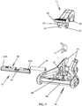
Figure 3 is an exploded view of the fastener ofFIG. 1 . -
Figure 4 is an alternate exploded view of the fastener ofFIG. 1 . -
Figure 5 is a plan view of the fastener ofFIG. 1 , unlocked. -
Figure 6 is a sectional view of the fastener ofFIG. 4 , taken along line A-A. -
Figure 7 is a sectional view of the fastener ofFIG. 4 , taken along line B-B. -
Figure 8 is a plan view of the fastener ofFIG. 1 , locked. -
Figure 9 is a sectional view of the fastener ofFIG. 4 , taken along line C-C. -
Figure 10 is a sectional view of the fastener ofFIG. 4 , taken along line D-D. -
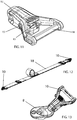
Figure 11 is an alternate perspective view of the fastener ofFIG. 1 . -
Figure 12 is a perspective view of the fastener ofFIG.1 in use on either end of a sling. -
Figure 13 is a perspective view of the fastener ofFIG. 1 , attached to a mounting loop. - With reference now to the drawings, the preferred embodiment of the locking snap-clip fastener is herein described.
- The following reference numerals are used to indicate the following components of the displayed preferred embodiment:
- 8
- - connection hardware;
- 10
- - fastener;
- 12
- - mandible;
- 13
- - spring;
- 14
- - maxilla;
- 1 5
- - roll pin;
- 16
- - lock bar;
- 18
- - sling;
- 22
- - stop;
- 24
- - distal tab;
- 26
- - hooked tooth;
- 28
- - lever;
- 40
- - cradle;
- 42
- - pivot hole;
- 43
- - floor;
- 44
- - channel;
- 45
- - tooth;
- 46
- - back ridge;
- 48
- - attachment bar;
- 62
- - first tapered end;
- 64
- - ridge;
- 66
- - off-center vertical notch;
- 68
- - second tapered end.
- With reference to
FIGS. 1 and 2 , two jaw bodies, amandible 12 and amaxilla 14, form thefastener 10.Maxilla 14cradles mandible 12. Themandible 12 andmaxilla 14 pivot relative to each other about aroll pin 15 and are biased in a closed position bytorsion spring 13.Lock bar 16 passes through a middle portion of themaxilla 14 and may selectively impede movement of themandible 12 relative thereto. This impediment allows thefastener 10 to be locked in an immovable position at the will of the user. -
Figures 3 and4 depict the components of the fastener in greater detail. Themandible 12 features a hookedtooth 26 on one end and alever 28 on the other. Twodistal tabs 24 are located on either side of themandible 12, roughly one third of the length of themandible 12 from a terminal end of thelever 28.Tabs 24 both feature coaxial through holes. Astop 22 is located on one side of themandible 12 underneath thelever 28 and behind onetab 24. Themaxilla 14 features acradle 40 which interfaces with the hookedtooth 26.Cradle 40 features afloor 43 and two sides, which each terminate in atooth 45, with space defined between eachtooth 45 and thefloor 43.Maxilla 14 also features anattachment bar 48 opposite the cradle. Theattachment bar 48 defines a hind end of themaxilla 14. Two pivot holes 42 are provided in opposite walls of themaxilla 14, such that, when properly positioned, the holes in thetabs 24 are coaxial with the pivot holes 42. Aroll pin 15 or similar structure is therein inserted to join themandible 12 andmaxilla 14 and serve as a pivot bar about which the jaw bodies respectively pivot.Torsion spring 13 is positioned about theroll pin 15, between thetabs 24, and is anchored with one arm in a slot on aback ridge 46 of the maxilla 14 (FIG. 11 ). Thetorsion spring 13 biases the jaw bodies in a closed position. - The locking
bar 16 passes through achannel 44 behind the pivot holes 42 in themaxilla 14. The locking bar features two tapered ends 62, 68, an off-centervertical notch 66 and aridge 64 residing in a similarly off-center horizontal notch. Together,ridge 64 and the horizontal notch form two detents on either side of theridge 64. When in position, the horizontal notch resides underneath the end of thespring 13 anchored in theback ridge 46. The interplay between these pieces is shown in a better view inFIG. 8 . - In use, shown in
FIGS. 5-10 , the lockingbar 16 is pushed to one side or the other. In an open position, shown inFIGS. 5-7 , stop 22 is positioned over thenotch 66, thereby allowing relative movement between themandible 12 andmaxilla 14.Spring 13 resides in an outer edge detent of theridge 64 in the horizontal notch. Spring pressure biases thespring 13 against the lockingbar 16 and maintains the locking bar's position. To lock the fastener, shown inFIGS. 8-10 , a user presses the exposed tapered end of the lockingbar 16 until enough force is applied to thespring 13 to cause it to jumpridge 64 and settle on its other side's detent. In this position, stop 22 is not positioned oververtical notch 66, but rather over a solid portion of the lockingbar 16. This then prevents themandible 12 andmaxilla 14 from pivoting and opening the fastener. The lockingbar 16 of the fastener then requires positive pressure from the user to switch from one position to another and remains in that position until the user consciously desires to change. - This
fastener 10 may be used in many different functions, such as thesling 18 shown inFIG. 12 . In any setting, a strap may be secured aboutattachment bar 48 in any of the known, conventional means. In use, shown inFIG. 1 3 , thefastener 10 is opened by unlocking it and depressing thelever 28 to separate themandible 12 from themaxilla 14. A piece ofconnection hardware 8, such as a ring or bar, is positioned between theteeth 45 andfloor 43 of themaxilla jaw 14 and thelever 28 released, thereby closing the hookedtooth 26 around the connection hardware. Thefastener 10 is then locked as described above. - The present invention is capable of being produced in industry and being used as an aid in portage and other fields where carrying or fastening an object to another object is required. This Application illustrates the invention as being in use with a sling; however, the invention is capable of use with other objects, most notably straps and packs, where temporary but secure fastening of two objects is required. The
attachment bar 48 is an example means by which the present invention is connected to the target object, in this case a sling. It should be readily appreciated that different attachment means may be utilized for different types of objects and different purposes. The present invention may be manufactured from any appropriate material, metals and plastics being considered ideal for durability and economical construction.
Claims (10)
- A clip fastener (10) comprising:a. two hingedly opposable jaws (12, 14), both jaws (12, 14) being biased into a closed position;b. a lock bar (16), situated within a channel (44) in one of the jaws (14) and capable of transverse slidable motion therethrough; andc. a spring;
characterized in that:the lock bar (16) comprises:i. a vertical notch (66) located off center of the lock bar (16);ii. a horizontal notch located off center of the lock bar (16) on an opposite side of the vertical notch (66); andiii. a ridge (64) residing within the horizontal notch such that two detents are formed by the ridge (64) and an interior of the horizontal notch;the spring is a torsion spring (13) with at least one arm; andthe clip fastener (10) further comprisesd. a stop tab (22), extending from one jaw (12) proximate the vertical notch (66);
wherein opening and closing the jaws (12, 14) defines a path of travel for the stop tab (22), the lock bar (16) residing within the path of travel and said arm of the torsion spring (13) resides within the horizontal notch of the lock bar (16) such that upon moving the lock bar (16) into open and closed positions the ridge (64) of the lock bar (16) may be selectably located upon either side of said arm of the torsion spring (13) thereby selectively positioning the vertical notch (66) of the lock bar (16) in the path of travel and allowing passage of the stop tab (22) and associated relative pivoting movement of the jaws (12, 14) when the lock bar (16) is in an open position. - A clip fastener (10) as claimed in claim 1, wherein said jaws (12, 14) pivot relative to each other about a roll pin (15), about which the torsion spring (13) is positioned.
- A clip fastener (10) as claimed in claim 2, in which the jaw (12) from which said stop tab (22) extends features a hooked tooth (26) on one end thereof and a lever (28) on the other end thereof.
- A clip fastener (10) as claimed in claim 3, wherein said stop tab (22) is located underneath said lever (28) and behind one of two distal tabs (24) located on either side of the jaw (12).
- A clip fastener (10) as claimed in claim 4, wherein said hooked tooth (26) is configured to interface with a cradle (40) of the other jaw (14) when the jaws (12, 14) are in said closed position.
- A clip fastener (10) as claimed in any of claims 1 to 4, comprising an attachment bar (48) opposite the cradle (40) for use in securing the clip fastener (10) to a strap.
- A locking mechanism for a fastener (10), the fastener (10) having two pivotable jaws (12, 14) and a torsion spring (13) therebetween having an upper arm and a lower arm and providing pivoting bias for said jaws (12, 14) into a closed position, the locking mechanism comprising:a. a transverse bar (16) having a top side, the transverse bar (16) being transversely slidable through one of the pivotable jaws (14) into, selectably, an open position and a closed position;the locking mechanism further comprises:
characterized in that:the transverse bar (16) comprises:i. a vertical notch (66) located off center of the lock bar (16);ii. a horizontal notch located off center of the lock bar (16) on an opposite side of the vertical notch (66); andiii a ridge (64) residing within the horizontal notch such that two detents are formed by the ridge (64) and an interior of the horizontal notch; andb. a stop tab (22), the stop tab (22) being configured to be located on one of the jaws (12) proximate the lock bar (16);
wherein, opening and closing the jaws defines a path of travel for the stop tab (22), the lock bar (16) residing within the path of travel, and said lower arm of the torsion spring (13) resides within the horizontal notch of the lock bar (16) such that upon moving the lock bar (16) into open and closed positions the ridge (64) of the lock bar (16) may be selectably located upon either side of said lower arm of the torsion spring (13) thereby selectively positioning the vertical notch (66) of the lock bar (16) in the path of travel and allowing passage of the stop tab (22) and associated relative pivoting movement of the jaws when the lock bar (16) is in an open position. - The locking mechanism of claim 7, the ridge (64) residing in a horizontal notch on the transverse bar (16).
- The locking mechanism of claim 8, the ridge (64) interfacing with the lower arm of the torsion spring (13) such that, when the transverse bar (16) is in an open position, the ridge (64) is on one side of the lower arm of the torsion spring (13) and, when the transverse bar (16) is in a closed position, the ridge (64) is on another side of the lower arm of the torsion spring (13).
- The locking mechanism of claim 7, the ridge (64) interfacing with the lower arm of the torsion spring (13) such that, when the transverse bar (16) is in an open position, the ridge (64) is on one side of the lower arm of the torsion spring (13) and, when the transverse bar (16) is in a closed position, the ridge (64) is on another side of the lower arm of the torsion spring (13).
Priority Applications (1)
| Application Number | Priority Date | Filing Date | Title |
|---|---|---|---|
| PL12830592T PL2753836T3 (en) | 2011-09-09 | 2012-09-07 | Lockable snap-clip fastener |
Applications Claiming Priority (3)
| Application Number | Priority Date | Filing Date | Title |
|---|---|---|---|
| US201161533104P | 2011-09-09 | 2011-09-09 | |
| US13/439,034 US8544153B2 (en) | 2011-09-09 | 2012-04-04 | Lockable snap-clip fastener |
| PCT/US2012/054303 WO2013036864A1 (en) | 2011-09-09 | 2012-09-07 | Lockable snap-clip fastener |
Publications (3)
| Publication Number | Publication Date |
|---|---|
| EP2753836A1 EP2753836A1 (en) | 2014-07-16 |
| EP2753836A4 EP2753836A4 (en) | 2015-05-06 |
| EP2753836B1 true EP2753836B1 (en) | 2016-12-14 |
Family
ID=47832612
Family Applications (1)
| Application Number | Title | Priority Date | Filing Date |
|---|---|---|---|
| EP12830592.7A Active EP2753836B1 (en) | 2011-09-09 | 2012-09-07 | Lockable snap-clip fastener |
Country Status (14)
| Country | Link |
|---|---|
| US (1) | US8544153B2 (en) |
| EP (1) | EP2753836B1 (en) |
| JP (1) | JP5902816B2 (en) |
| KR (1) | KR101610564B1 (en) |
| CN (1) | CN103842666B (en) |
| AU (1) | AU2012304354B2 (en) |
| BR (1) | BR112014005359B1 (en) |
| CA (1) | CA2847539C (en) |
| DK (1) | DK2753836T3 (en) |
| ES (1) | ES2618504T3 (en) |
| IL (1) | IL231332B (en) |
| PL (1) | PL2753836T3 (en) |
| SG (1) | SG11201400402RA (en) |
| WO (1) | WO2013036864A1 (en) |
Families Citing this family (24)
| Publication number | Priority date | Publication date | Assignee | Title |
|---|---|---|---|---|
| TWI482732B (en) * | 2012-10-03 | 2015-05-01 | Yoke Ind Corp | Lock the hook |
| US9610798B2 (en) * | 2013-02-20 | 2017-04-04 | Typical 4, LLC | Trophy mount and skull clamp |
| US10195355B2 (en) * | 2013-04-22 | 2019-02-05 | Sanofi-Aventis Deutschland Gmbh | Supplementary device for a manually operable injection device |
| US9921029B2 (en) | 2014-01-10 | 2018-03-20 | Magpul Industries Corp. | Connector |
| US9243866B2 (en) | 2014-01-10 | 2016-01-26 | Magpul Industries Corp. | Paraclip adapter |
| US9239210B2 (en) | 2014-04-03 | 2016-01-19 | Magpul Industries Corp. | Firearm accessory mounting interface |
| USD724995S1 (en) * | 2014-01-21 | 2015-03-24 | Woojin Plastic Co., Ltd. | Buckle for bag |
| US9366043B2 (en) * | 2014-05-28 | 2016-06-14 | Mrm Hk Limited | Safety tether for a hand-held article |
| USD829089S1 (en) * | 2014-07-08 | 2018-09-25 | Woojin Plastic Co., Ltd. | Tent cord adjuster |
| US9447815B2 (en) | 2014-10-31 | 2016-09-20 | Magpul Industries Corp. | Quick detach accessory attachment |
| US9835407B2 (en) * | 2015-12-30 | 2017-12-05 | McLean Corp. | Apparatus for changing between a two-point sling state and a one-point sling state |
| CN205717059U (en) * | 2016-05-03 | 2016-11-23 | 中山市尊宝实业有限公司 | A kind of convenient spring carrier arm installed |
| US10371183B2 (en) * | 2016-11-01 | 2019-08-06 | Ty-Flot, Inc. | Locking badge clamp |
| USD869594S1 (en) | 2018-01-18 | 2019-12-10 | Vista Outdoor Operations Llc | Buckle for a rifle sling |
| US10209031B2 (en) | 2017-07-20 | 2019-02-19 | Vista Outdoor Operations Llc | Rapid adjust buckle with integral flexible pull loop |
| USD960278S1 (en) | 2017-07-20 | 2022-08-09 | Vista Outdoor Operations Llc | Buckle for a rifle sling |
| CN107687473A (en) * | 2017-09-30 | 2018-02-13 | 南京际华三五二特种装备有限公司 | A kind of Self-locking hanging hook |
| US10634450B1 (en) | 2018-03-29 | 2020-04-28 | Luke May | Firearm stablizing clip |
| JP6907994B2 (en) * | 2018-04-20 | 2021-07-21 | カシオ計算機株式会社 | clip |
| US10493243B1 (en) * | 2018-04-23 | 2019-12-03 | Antonio Braham | Respiratory airway and intravenous extension system (RAIVES) |
| GB201811437D0 (en) * | 2018-07-12 | 2018-08-29 | Andersen Jesper | Safety latch |
| CN110529469B (en) * | 2019-09-02 | 2020-12-22 | 深圳市绿联科技有限公司 | Clamp mechanism |
| USD989906S1 (en) * | 2020-06-19 | 2023-06-20 | Aaron Knirr | Swivel mount sling adapter |
| CN115194431A (en) * | 2021-04-01 | 2022-10-18 | A·雷蒙德公司 | Lock for retaining a first component to a second component and assembly of the first component and the second component |
Family Cites Families (25)
| Publication number | Priority date | Publication date | Assignee | Title |
|---|---|---|---|---|
| US186637A (en) * | 1877-01-23 | Improvement in snap-hooks | ||
| US1032369A (en) * | 1909-10-14 | 1912-07-16 | Covert Mfg Company | Spring-tongue snap. |
| US2896288A (en) * | 1957-01-11 | 1959-07-28 | Frank L Davis | Web end connector |
| US3074136A (en) * | 1960-10-12 | 1963-01-22 | Brown Line Corp | Web end connectors |
| US3358340A (en) * | 1965-10-23 | 1967-12-19 | Davis Aircraft Products Inc | Bridle buckle |
| FR2303986A1 (en) | 1975-03-14 | 1976-10-08 | Pest Robert | Automatically latching hook for safety harness - has spring loaded closing link latched by spring loaded pin when shut |
| US4379579A (en) * | 1981-12-16 | 1983-04-12 | The B. F. Goodrich Company | Automatic locking and ejecting hook assembly |
| US4667379A (en) * | 1986-05-14 | 1987-05-26 | Salvatore Tumminello, Jr. | Jewelry clasp |
| US5279021A (en) * | 1992-08-26 | 1994-01-18 | Edgin Howard L | Article retaining apparatus having pull-release/push-retain structure and method of using |
| JPH06300030A (en) | 1993-04-13 | 1994-10-25 | Yoshida Kogyo Kk <Ykk> | Eggplant ring |
| FR2731255B1 (en) * | 1995-03-02 | 1997-04-25 | Zedel | LOCKING RING CARABINER |
| JP3335547B2 (en) * | 1996-03-13 | 2002-10-21 | 富士機工株式会社 | Lock mechanism |
| JP3829158B2 (en) * | 1996-04-04 | 2006-10-04 | 株式会社ヤマ | Joint for jewelry |
| US6505487B1 (en) | 2000-09-21 | 2003-01-14 | Dell Products, L.P. | Locking device for use with a projection lock and method for securing an object with a projection lock |
| US6539885B2 (en) | 2001-05-25 | 2003-04-01 | Timothy Tylaska | Locking shackle apparatus |
| US6530196B1 (en) * | 2001-11-30 | 2003-03-11 | Coastal Pet Products, Inc. | Snap connector |
| FR2834870B1 (en) * | 2002-01-18 | 2004-03-19 | Zedel | FIXING LOOP WITH SELF-LOCKING AND ADJUSTMENT OF A STRAP |
| US6588076B1 (en) | 2002-04-08 | 2003-07-08 | Gary E. Choate | Carabiner with locking gate |
| CN2608472Y (en) * | 2003-04-14 | 2004-03-31 | 洪荣德 | Hooks for chains that can be connected in series |
| JP4597687B2 (en) | 2004-01-27 | 2010-12-15 | コンビ株式会社 | clip |
| EP1957024A4 (en) | 2005-12-05 | 2009-05-13 | Scott M Ahlman | Patient single surface system |
| CN201167657Y (en) * | 2008-02-04 | 2008-12-24 | 竞泰股份有限公司 | Braces subassembly and hook and loop structure thereof |
| US8042235B2 (en) * | 2009-05-26 | 2011-10-25 | Taiwan Racing Products Co., Ltd. | Buckling device for safety belt |
| USD632954S1 (en) * | 2010-01-18 | 2011-02-22 | Magpul Industries Corporation | Snap clip for a sling |
| USD679580S1 (en) * | 2011-08-26 | 2013-04-09 | Magpul Industries Corporation | Snap clip |
-
2012
- 2012-04-04 US US13/439,034 patent/US8544153B2/en active Active
- 2012-09-07 SG SG11201400402RA patent/SG11201400402RA/en unknown
- 2012-09-07 KR KR1020147009230A patent/KR101610564B1/en active Active
- 2012-09-07 WO PCT/US2012/054303 patent/WO2013036864A1/en not_active Ceased
- 2012-09-07 AU AU2012304354A patent/AU2012304354B2/en active Active
- 2012-09-07 DK DK12830592.7T patent/DK2753836T3/en active
- 2012-09-07 EP EP12830592.7A patent/EP2753836B1/en active Active
- 2012-09-07 ES ES12830592.7T patent/ES2618504T3/en active Active
- 2012-09-07 CN CN201280043748.9A patent/CN103842666B/en active Active
- 2012-09-07 JP JP2014529918A patent/JP5902816B2/en active Active
- 2012-09-07 BR BR112014005359-6A patent/BR112014005359B1/en active IP Right Grant
- 2012-09-07 CA CA2847539A patent/CA2847539C/en active Active
- 2012-09-07 PL PL12830592T patent/PL2753836T3/en unknown
-
2014
- 2014-03-05 IL IL231332A patent/IL231332B/en active IP Right Grant
Non-Patent Citations (1)
| Title |
|---|
| None * |
Also Published As
| Publication number | Publication date |
|---|---|
| CN103842666B (en) | 2016-03-09 |
| US20130097822A1 (en) | 2013-04-25 |
| JP5902816B2 (en) | 2016-04-13 |
| NZ622516A (en) | 2016-07-29 |
| KR101610564B1 (en) | 2016-04-07 |
| ES2618504T3 (en) | 2017-06-21 |
| IL231332B (en) | 2019-05-30 |
| AU2012304354A1 (en) | 2014-04-10 |
| KR20140059293A (en) | 2014-05-15 |
| IL231332A0 (en) | 2014-04-30 |
| US8544153B2 (en) | 2013-10-01 |
| CN103842666A (en) | 2014-06-04 |
| AU2012304354B2 (en) | 2015-12-03 |
| EP2753836A1 (en) | 2014-07-16 |
| PL2753836T3 (en) | 2017-07-31 |
| BR112014005359B1 (en) | 2020-12-08 |
| DK2753836T3 (en) | 2017-03-20 |
| SG11201400402RA (en) | 2014-04-28 |
| EP2753836A4 (en) | 2015-05-06 |
| CA2847539A1 (en) | 2013-03-14 |
| BR112014005359A2 (en) | 2017-06-13 |
| JP2015503063A (en) | 2015-01-29 |
| CA2847539C (en) | 2016-04-19 |
| WO2013036864A1 (en) | 2013-03-14 |
Similar Documents
| Publication | Publication Date | Title |
|---|---|---|
| CA2847539C (en) | Lockable snap-clip fastener | |
| US9500438B2 (en) | Lockable snap-clip fastener | |
| CN103653566B (en) | Zipper fasteners and luggage | |
| EP2130451B1 (en) | Carrying case with locking latch mechanism | |
| US20160153487A1 (en) | Fastener with improved gate | |
| US20110005047A1 (en) | Adjustable cam buckle | |
| EP2959789B1 (en) | Zip fastener | |
| US20050193531A1 (en) | Snap hook having lockable pivotal gate | |
| EP2961293B1 (en) | Zip slider | |
| EP0884072A1 (en) | Buckle particularly for the heel strap of open heel swim fins | |
| WO2023099264A1 (en) | Belt strap closure | |
| US20030140461A1 (en) | Buckle | |
| US20090106957A1 (en) | Buckle device | |
| US9382939B1 (en) | Linkless attachment arrangement for a locking snap-hook or the like | |
| US20070226961A1 (en) | Buckle assembly | |
| DE102021213554B3 (en) | connecting device | |
| DE102021213555B3 (en) | webbing closure | |
| HK1195112A (en) | Lockable snap-clip fastener | |
| HK1195112B (en) | Lockable snap-clip fastener | |
| US20160166016A1 (en) | Buckle arrangement | |
| US20090139464A1 (en) | Animal Restraint with Snap Hook and Buckle | |
| EP4210533A1 (en) | Connecting apparatus | |
| NZ622516B2 (en) | Lockable snap-clip fastener | |
| DE102021213558B3 (en) | connecting device | |
| US11737522B2 (en) | Locking buckle |
Legal Events
| Date | Code | Title | Description |
|---|---|---|---|
| PUAI | Public reference made under article 153(3) epc to a published international application that has entered the european phase |
Free format text: ORIGINAL CODE: 0009012 |
|
| 17P | Request for examination filed |
Effective date: 20140402 |
|
| AK | Designated contracting states |
Kind code of ref document: A1 Designated state(s): AL AT BE BG CH CY CZ DE DK EE ES FI FR GB GR HR HU IE IS IT LI LT LU LV MC MK MT NL NO PL PT RO RS SE SI SK SM TR |
|
| REG | Reference to a national code |
Ref country code: HK Ref legal event code: DE Ref document number: 1195112 Country of ref document: HK |
|
| DAX | Request for extension of the european patent (deleted) | ||
| RA4 | Supplementary search report drawn up and despatched (corrected) |
Effective date: 20150407 |
|
| RIC1 | Information provided on ipc code assigned before grant |
Ipc: F41C 23/02 20060101ALI20150330BHEP Ipc: F16B 45/02 20060101AFI20150330BHEP |
|
| GRAP | Despatch of communication of intention to grant a patent |
Free format text: ORIGINAL CODE: EPIDOSNIGR1 |
|
| INTG | Intention to grant announced |
Effective date: 20160622 |
|
| GRAS | Grant fee paid |
Free format text: ORIGINAL CODE: EPIDOSNIGR3 |
|
| GRAA | (expected) grant |
Free format text: ORIGINAL CODE: 0009210 |
|
| AK | Designated contracting states |
Kind code of ref document: B1 Designated state(s): AL AT BE BG CH CY CZ DE DK EE ES FI FR GB GR HR HU IE IS IT LI LT LU LV MC MK MT NL NO PL PT RO RS SE SI SK SM TR |
|
| REG | Reference to a national code |
Ref country code: GB Ref legal event code: FG4D |
|
| REG | Reference to a national code |
Ref country code: CH Ref legal event code: EP |
|
| REG | Reference to a national code |
Ref country code: IE Ref legal event code: FG4D |
|
| REG | Reference to a national code |
Ref country code: AT Ref legal event code: REF Ref document number: 853869 Country of ref document: AT Kind code of ref document: T Effective date: 20170115 |
|
| REG | Reference to a national code |
Ref country code: DE Ref legal event code: R096 Ref document number: 602012026707 Country of ref document: DE |
|
| PG25 | Lapsed in a contracting state [announced via postgrant information from national office to epo] |
Ref country code: LV Free format text: LAPSE BECAUSE OF FAILURE TO SUBMIT A TRANSLATION OF THE DESCRIPTION OR TO PAY THE FEE WITHIN THE PRESCRIBED TIME-LIMIT Effective date: 20161214 |
|
| REG | Reference to a national code |
Ref country code: SE Ref legal event code: TRGR |
|
| REG | Reference to a national code |
Ref country code: DK Ref legal event code: T3 Effective date: 20170315 |
|
| REG | Reference to a national code |
Ref country code: LT Ref legal event code: MG4D |
|
| REG | Reference to a national code |
Ref country code: NL Ref legal event code: MP Effective date: 20161214 |
|
| PG25 | Lapsed in a contracting state [announced via postgrant information from national office to epo] |
Ref country code: GR Free format text: LAPSE BECAUSE OF FAILURE TO SUBMIT A TRANSLATION OF THE DESCRIPTION OR TO PAY THE FEE WITHIN THE PRESCRIBED TIME-LIMIT Effective date: 20170315 Ref country code: LT Free format text: LAPSE BECAUSE OF FAILURE TO SUBMIT A TRANSLATION OF THE DESCRIPTION OR TO PAY THE FEE WITHIN THE PRESCRIBED TIME-LIMIT Effective date: 20161214 |
|
| REG | Reference to a national code |
Ref country code: AT Ref legal event code: MK05 Ref document number: 853869 Country of ref document: AT Kind code of ref document: T Effective date: 20161214 Ref country code: NO Ref legal event code: T2 Effective date: 20161214 |
|
| PG25 | Lapsed in a contracting state [announced via postgrant information from national office to epo] |
Ref country code: RS Free format text: LAPSE BECAUSE OF FAILURE TO SUBMIT A TRANSLATION OF THE DESCRIPTION OR TO PAY THE FEE WITHIN THE PRESCRIBED TIME-LIMIT Effective date: 20161214 Ref country code: HR Free format text: LAPSE BECAUSE OF FAILURE TO SUBMIT A TRANSLATION OF THE DESCRIPTION OR TO PAY THE FEE WITHIN THE PRESCRIBED TIME-LIMIT Effective date: 20161214 |
|
| REG | Reference to a national code |
Ref country code: ES Ref legal event code: FG2A Ref document number: 2618504 Country of ref document: ES Kind code of ref document: T3 Effective date: 20170621 |
|
| PG25 | Lapsed in a contracting state [announced via postgrant information from national office to epo] |
Ref country code: NL Free format text: LAPSE BECAUSE OF FAILURE TO SUBMIT A TRANSLATION OF THE DESCRIPTION OR TO PAY THE FEE WITHIN THE PRESCRIBED TIME-LIMIT Effective date: 20161214 |
|
| PG25 | Lapsed in a contracting state [announced via postgrant information from national office to epo] |
Ref country code: IS Free format text: LAPSE BECAUSE OF FAILURE TO SUBMIT A TRANSLATION OF THE DESCRIPTION OR TO PAY THE FEE WITHIN THE PRESCRIBED TIME-LIMIT Effective date: 20170414 Ref country code: EE Free format text: LAPSE BECAUSE OF FAILURE TO SUBMIT A TRANSLATION OF THE DESCRIPTION OR TO PAY THE FEE WITHIN THE PRESCRIBED TIME-LIMIT Effective date: 20161214 Ref country code: CZ Free format text: LAPSE BECAUSE OF FAILURE TO SUBMIT A TRANSLATION OF THE DESCRIPTION OR TO PAY THE FEE WITHIN THE PRESCRIBED TIME-LIMIT Effective date: 20161214 Ref country code: RO Free format text: LAPSE BECAUSE OF FAILURE TO SUBMIT A TRANSLATION OF THE DESCRIPTION OR TO PAY THE FEE WITHIN THE PRESCRIBED TIME-LIMIT Effective date: 20161214 Ref country code: SK Free format text: LAPSE BECAUSE OF FAILURE TO SUBMIT A TRANSLATION OF THE DESCRIPTION OR TO PAY THE FEE WITHIN THE PRESCRIBED TIME-LIMIT Effective date: 20161214 |
|
| REG | Reference to a national code |
Ref country code: FR Ref legal event code: PLFP Year of fee payment: 6 |
|
| PG25 | Lapsed in a contracting state [announced via postgrant information from national office to epo] |
Ref country code: SM Free format text: LAPSE BECAUSE OF FAILURE TO SUBMIT A TRANSLATION OF THE DESCRIPTION OR TO PAY THE FEE WITHIN THE PRESCRIBED TIME-LIMIT Effective date: 20161214 Ref country code: PT Free format text: LAPSE BECAUSE OF FAILURE TO SUBMIT A TRANSLATION OF THE DESCRIPTION OR TO PAY THE FEE WITHIN THE PRESCRIBED TIME-LIMIT Effective date: 20170414 Ref country code: AT Free format text: LAPSE BECAUSE OF FAILURE TO SUBMIT A TRANSLATION OF THE DESCRIPTION OR TO PAY THE FEE WITHIN THE PRESCRIBED TIME-LIMIT Effective date: 20161214 Ref country code: BE Free format text: LAPSE BECAUSE OF FAILURE TO SUBMIT A TRANSLATION OF THE DESCRIPTION OR TO PAY THE FEE WITHIN THE PRESCRIBED TIME-LIMIT Effective date: 20161214 Ref country code: BG Free format text: LAPSE BECAUSE OF FAILURE TO SUBMIT A TRANSLATION OF THE DESCRIPTION OR TO PAY THE FEE WITHIN THE PRESCRIBED TIME-LIMIT Effective date: 20170314 |
|
| REG | Reference to a national code |
Ref country code: DE Ref legal event code: R097 Ref document number: 602012026707 Country of ref document: DE |
|
| PLBE | No opposition filed within time limit |
Free format text: ORIGINAL CODE: 0009261 |
|
| STAA | Information on the status of an ep patent application or granted ep patent |
Free format text: STATUS: NO OPPOSITION FILED WITHIN TIME LIMIT |
|
| 26N | No opposition filed |
Effective date: 20170915 |
|
| REG | Reference to a national code |
Ref country code: HK Ref legal event code: GR Ref document number: 1195112 Country of ref document: HK |
|
| PG25 | Lapsed in a contracting state [announced via postgrant information from national office to epo] |
Ref country code: SI Free format text: LAPSE BECAUSE OF FAILURE TO SUBMIT A TRANSLATION OF THE DESCRIPTION OR TO PAY THE FEE WITHIN THE PRESCRIBED TIME-LIMIT Effective date: 20161214 |
|
| REG | Reference to a national code |
Ref country code: CH Ref legal event code: PL |
|
| PG25 | Lapsed in a contracting state [announced via postgrant information from national office to epo] |
Ref country code: MC Free format text: LAPSE BECAUSE OF FAILURE TO SUBMIT A TRANSLATION OF THE DESCRIPTION OR TO PAY THE FEE WITHIN THE PRESCRIBED TIME-LIMIT Effective date: 20161214 |
|
| REG | Reference to a national code |
Ref country code: IE Ref legal event code: MM4A |
|
| PG25 | Lapsed in a contracting state [announced via postgrant information from national office to epo] |
Ref country code: LU Free format text: LAPSE BECAUSE OF NON-PAYMENT OF DUE FEES Effective date: 20170907 |
|
| PG25 | Lapsed in a contracting state [announced via postgrant information from national office to epo] |
Ref country code: IE Free format text: LAPSE BECAUSE OF NON-PAYMENT OF DUE FEES Effective date: 20170907 Ref country code: CH Free format text: LAPSE BECAUSE OF NON-PAYMENT OF DUE FEES Effective date: 20170930 Ref country code: LI Free format text: LAPSE BECAUSE OF NON-PAYMENT OF DUE FEES Effective date: 20170930 |
|
| REG | Reference to a national code |
Ref country code: FR Ref legal event code: PLFP Year of fee payment: 7 |
|
| PG25 | Lapsed in a contracting state [announced via postgrant information from national office to epo] |
Ref country code: MT Free format text: LAPSE BECAUSE OF NON-PAYMENT OF DUE FEES Effective date: 20170907 |
|
| PG25 | Lapsed in a contracting state [announced via postgrant information from national office to epo] |
Ref country code: HU Free format text: LAPSE BECAUSE OF FAILURE TO SUBMIT A TRANSLATION OF THE DESCRIPTION OR TO PAY THE FEE WITHIN THE PRESCRIBED TIME-LIMIT; INVALID AB INITIO Effective date: 20120907 |
|
| PG25 | Lapsed in a contracting state [announced via postgrant information from national office to epo] |
Ref country code: CY Free format text: LAPSE BECAUSE OF NON-PAYMENT OF DUE FEES Effective date: 20161214 |
|
| PG25 | Lapsed in a contracting state [announced via postgrant information from national office to epo] |
Ref country code: MK Free format text: LAPSE BECAUSE OF FAILURE TO SUBMIT A TRANSLATION OF THE DESCRIPTION OR TO PAY THE FEE WITHIN THE PRESCRIBED TIME-LIMIT Effective date: 20161214 |
|
| PG25 | Lapsed in a contracting state [announced via postgrant information from national office to epo] |
Ref country code: TR Free format text: LAPSE BECAUSE OF FAILURE TO SUBMIT A TRANSLATION OF THE DESCRIPTION OR TO PAY THE FEE WITHIN THE PRESCRIBED TIME-LIMIT Effective date: 20161214 |
|
| PG25 | Lapsed in a contracting state [announced via postgrant information from national office to epo] |
Ref country code: AL Free format text: LAPSE BECAUSE OF FAILURE TO SUBMIT A TRANSLATION OF THE DESCRIPTION OR TO PAY THE FEE WITHIN THE PRESCRIBED TIME-LIMIT Effective date: 20161214 |
|
| REG | Reference to a national code |
Ref country code: DE Ref legal event code: R082 Ref document number: 602012026707 Country of ref document: DE Representative=s name: KILBURN & STRODE LLP, NL |
|
| PGFP | Annual fee paid to national office [announced via postgrant information from national office to epo] |
Ref country code: FI Payment date: 20250805 Year of fee payment: 14 |
|
| PGFP | Annual fee paid to national office [announced via postgrant information from national office to epo] |
Ref country code: DK Payment date: 20250805 Year of fee payment: 14 Ref country code: DE Payment date: 20250806 Year of fee payment: 14 |
|
| PGFP | Annual fee paid to national office [announced via postgrant information from national office to epo] |
Ref country code: NO Payment date: 20250807 Year of fee payment: 14 |
|
| PGFP | Annual fee paid to national office [announced via postgrant information from national office to epo] |
Ref country code: PL Payment date: 20250714 Year of fee payment: 14 Ref country code: IT Payment date: 20250807 Year of fee payment: 14 |
|
| PGFP | Annual fee paid to national office [announced via postgrant information from national office to epo] |
Ref country code: GB Payment date: 20250805 Year of fee payment: 14 |
|
| PGFP | Annual fee paid to national office [announced via postgrant information from national office to epo] |
Ref country code: FR Payment date: 20250807 Year of fee payment: 14 |
|
| PGFP | Annual fee paid to national office [announced via postgrant information from national office to epo] |
Ref country code: SE Payment date: 20250805 Year of fee payment: 14 |
|
| PGFP | Annual fee paid to national office [announced via postgrant information from national office to epo] |
Ref country code: ES Payment date: 20251010 Year of fee payment: 14 |