EP2752812A1 - Charging infrastructure information providing system, charging infrastructure information providing device, control method and program - Google Patents
Charging infrastructure information providing system, charging infrastructure information providing device, control method and program Download PDFInfo
- Publication number
- EP2752812A1 EP2752812A1 EP12837489.9A EP12837489A EP2752812A1 EP 2752812 A1 EP2752812 A1 EP 2752812A1 EP 12837489 A EP12837489 A EP 12837489A EP 2752812 A1 EP2752812 A1 EP 2752812A1
- Authority
- EP
- European Patent Office
- Prior art keywords
- power
- charging infrastructure
- information
- information providing
- charging
- Prior art date
- Legal status (The legal status is an assumption and is not a legal conclusion. Google has not performed a legal analysis and makes no representation as to the accuracy of the status listed.)
- Granted
Links
Images



Classifications
-
- B—PERFORMING OPERATIONS; TRANSPORTING
- B60—VEHICLES IN GENERAL
- B60L—PROPULSION OF ELECTRICALLY-PROPELLED VEHICLES; SUPPLYING ELECTRIC POWER FOR AUXILIARY EQUIPMENT OF ELECTRICALLY-PROPELLED VEHICLES; ELECTRODYNAMIC BRAKE SYSTEMS FOR VEHICLES IN GENERAL; MAGNETIC SUSPENSION OR LEVITATION FOR VEHICLES; MONITORING OPERATING VARIABLES OF ELECTRICALLY-PROPELLED VEHICLES; ELECTRIC SAFETY DEVICES FOR ELECTRICALLY-PROPELLED VEHICLES
- B60L53/00—Methods of charging batteries, specially adapted for electric vehicles; Charging stations or on-board charging equipment therefor; Exchange of energy storage elements in electric vehicles
- B60L53/60—Monitoring or controlling charging stations
- B60L53/67—Controlling two or more charging stations
-
- B—PERFORMING OPERATIONS; TRANSPORTING
- B60—VEHICLES IN GENERAL
- B60L—PROPULSION OF ELECTRICALLY-PROPELLED VEHICLES; SUPPLYING ELECTRIC POWER FOR AUXILIARY EQUIPMENT OF ELECTRICALLY-PROPELLED VEHICLES; ELECTRODYNAMIC BRAKE SYSTEMS FOR VEHICLES IN GENERAL; MAGNETIC SUSPENSION OR LEVITATION FOR VEHICLES; MONITORING OPERATING VARIABLES OF ELECTRICALLY-PROPELLED VEHICLES; ELECTRIC SAFETY DEVICES FOR ELECTRICALLY-PROPELLED VEHICLES
- B60L53/00—Methods of charging batteries, specially adapted for electric vehicles; Charging stations or on-board charging equipment therefor; Exchange of energy storage elements in electric vehicles
- B60L53/60—Monitoring or controlling charging stations
- B60L53/66—Data transfer between charging stations and vehicles
-
- H—ELECTRICITY
- H02—GENERATION; CONVERSION OR DISTRIBUTION OF ELECTRIC POWER
- H02J—ELECTRIC POWER NETWORKS; CIRCUIT ARRANGEMENTS OR SYSTEMS FOR SUPPLYING OR DISTRIBUTING ELECTRIC POWER; SYSTEMS FOR STORING ELECTRIC ENERGY
- H02J7/00—Circuit arrangements for charging or discharging batteries or for supplying loads from batteries
- H02J7/50—Circuit arrangements for charging or discharging batteries or for supplying loads from batteries acting upon multiple batteries simultaneously or sequentially
-
- H—ELECTRICITY
- H02—GENERATION; CONVERSION OR DISTRIBUTION OF ELECTRIC POWER
- H02J—ELECTRIC POWER NETWORKS; CIRCUIT ARRANGEMENTS OR SYSTEMS FOR SUPPLYING OR DISTRIBUTING ELECTRIC POWER; SYSTEMS FOR STORING ELECTRIC ENERGY
- H02J7/00—Circuit arrangements for charging or discharging batteries or for supplying loads from batteries
- H02J7/70—Circuit arrangements for charging or discharging batteries or for supplying loads from batteries characterised by the mechanical construction
-
- H—ELECTRICITY
- H02—GENERATION; CONVERSION OR DISTRIBUTION OF ELECTRIC POWER
- H02J—ELECTRIC POWER NETWORKS; CIRCUIT ARRANGEMENTS OR SYSTEMS FOR SUPPLYING OR DISTRIBUTING ELECTRIC POWER; SYSTEMS FOR STORING ELECTRIC ENERGY
- H02J2105/00—Networks for supplying or distributing electric power characterised by their spatial reach or by the load
- H02J2105/30—Networks for supplying or distributing electric power characterised by their spatial reach or by the load the load networks being external to vehicles, i.e. exchanging power with vehicles
- H02J2105/33—Networks for supplying or distributing electric power characterised by their spatial reach or by the load the load networks being external to vehicles, i.e. exchanging power with vehicles exchanging power with road vehicles
- H02J2105/37—Networks for supplying or distributing electric power characterised by their spatial reach or by the load the load networks being external to vehicles, i.e. exchanging power with vehicles exchanging power with road vehicles exchanging power with electric vehicles [EV] or with hybrid electric vehicles [HEV]
-
- Y—GENERAL TAGGING OF NEW TECHNOLOGICAL DEVELOPMENTS; GENERAL TAGGING OF CROSS-SECTIONAL TECHNOLOGIES SPANNING OVER SEVERAL SECTIONS OF THE IPC; TECHNICAL SUBJECTS COVERED BY FORMER USPC CROSS-REFERENCE ART COLLECTIONS [XRACs] AND DIGESTS
- Y02—TECHNOLOGIES OR APPLICATIONS FOR MITIGATION OR ADAPTATION AGAINST CLIMATE CHANGE
- Y02T—CLIMATE CHANGE MITIGATION TECHNOLOGIES RELATED TO TRANSPORTATION
- Y02T10/00—Road transport of goods or passengers
- Y02T10/60—Other road transportation technologies with climate change mitigation effect
- Y02T10/70—Energy storage systems for electromobility, e.g. batteries
-
- Y—GENERAL TAGGING OF NEW TECHNOLOGICAL DEVELOPMENTS; GENERAL TAGGING OF CROSS-SECTIONAL TECHNOLOGIES SPANNING OVER SEVERAL SECTIONS OF THE IPC; TECHNICAL SUBJECTS COVERED BY FORMER USPC CROSS-REFERENCE ART COLLECTIONS [XRACs] AND DIGESTS
- Y02—TECHNOLOGIES OR APPLICATIONS FOR MITIGATION OR ADAPTATION AGAINST CLIMATE CHANGE
- Y02T—CLIMATE CHANGE MITIGATION TECHNOLOGIES RELATED TO TRANSPORTATION
- Y02T10/00—Road transport of goods or passengers
- Y02T10/60—Other road transportation technologies with climate change mitigation effect
- Y02T10/7072—Electromobility specific charging systems or methods for batteries, ultracapacitors, supercapacitors or double-layer capacitors
-
- Y—GENERAL TAGGING OF NEW TECHNOLOGICAL DEVELOPMENTS; GENERAL TAGGING OF CROSS-SECTIONAL TECHNOLOGIES SPANNING OVER SEVERAL SECTIONS OF THE IPC; TECHNICAL SUBJECTS COVERED BY FORMER USPC CROSS-REFERENCE ART COLLECTIONS [XRACs] AND DIGESTS
- Y02—TECHNOLOGIES OR APPLICATIONS FOR MITIGATION OR ADAPTATION AGAINST CLIMATE CHANGE
- Y02T—CLIMATE CHANGE MITIGATION TECHNOLOGIES RELATED TO TRANSPORTATION
- Y02T90/00—Enabling technologies or technologies with a potential or indirect contribution to GHG emissions mitigation
- Y02T90/10—Technologies relating to charging of electric vehicles
- Y02T90/12—Electric charging stations
-
- Y—GENERAL TAGGING OF NEW TECHNOLOGICAL DEVELOPMENTS; GENERAL TAGGING OF CROSS-SECTIONAL TECHNOLOGIES SPANNING OVER SEVERAL SECTIONS OF THE IPC; TECHNICAL SUBJECTS COVERED BY FORMER USPC CROSS-REFERENCE ART COLLECTIONS [XRACs] AND DIGESTS
- Y02—TECHNOLOGIES OR APPLICATIONS FOR MITIGATION OR ADAPTATION AGAINST CLIMATE CHANGE
- Y02T—CLIMATE CHANGE MITIGATION TECHNOLOGIES RELATED TO TRANSPORTATION
- Y02T90/00—Enabling technologies or technologies with a potential or indirect contribution to GHG emissions mitigation
- Y02T90/10—Technologies relating to charging of electric vehicles
- Y02T90/16—Information or communication technologies improving the operation of electric vehicles
Definitions
- the present invention relates to a charging infrastructure information providing system, a charging infrastructure information providing device, a control method, and a program.
- the present invention relates to a charging infrastructure information providing system and a charging infrastructure information providing device that provide charging infrastructure information to users of electric vehicles, a control method of controlling the charging infrastructure information providing device, and a program for the charging infrastructure information providing device.
- Non Patent Literature 1 proposes an idea of energy informationization to aim for construction of a new ultra-distributed energy social infrastructure by integration of power networks and information networks. More specifically, the research and development disclosed in Non Patent Literature 1 proposes execution of energy management in consideration of not only quantitative energy saving but also a reduction in the amount of generated carbon dioxide by distinguishing powers of respective power supplies from each other when a plurality of power sources are installed in households.
- Patent Literature 1 since the power from each power supply is supplied in association with information regarding this power supply, realization of various types of energy management in light of differences between the power supplies can be considered to be enabled by referring to the information.
- Patent Literature 1 does not propose energy management realized due to a difference between the power supplies by setting a charging infrastructure of electric vehicles as a target.
- a charging infrastructure information providing system providing information regarding charging infrastructures to a user of an electric vehicle.
- the charging infrastructure information providing system includes a charging infrastructure information providing device configured to provide the information regarding each charging infrastructure to the user of the electric vehicle.
- the charging infrastructure information providing device includes a charging infrastructure information providing unit configured to preferentially provide information regarding a charging infrastructure making a considerable contribution to supply of power of a predetermined attribute to a user terminal of the user of the electric vehicle.
- the charging infrastructure information providing device may further include a contribution evaluation unit configured to evaluate a contribution to supply of the power of the predetermined attribute in each charging infrastructure based on information regarding an amount of power fed to the electric vehicle in each charging infrastructure and attribute information of the power.
- the charging infrastructure information providing unit of the charging infrastructure information providing device may preferentially provide the information regarding the charging infrastructure making the considerable contribution to the supply of the power of the predetermined attribute based on a result evaluated by the contribution evaluation unit.
- the charging infrastructure information providing device may further include a power-feed information storage unit configured to sequentially store the information regarding the amount of power fed to the electric vehicle in each charging infrastructure and the attribute information of the power in association therewith.
- the contribution evaluation unit of the charging infrastructure information providing device may evaluate the contribution to the supply of the power of the predetermined attribute in each charging infrastructure based on the information stored in the power-feed information storage unit.
- the charging infrastructure information providing system may further include a plurality of charging infrastructure devices configured to be installed in the plurality of charging infrastructures, respectively, and manage information regarding power fed from a charger of the charging infrastructure to the electric vehicle.
- Each of the charging infrastructure devices may include a power-feed data transmission unit configured to transmit power-feed data including the information regarding the amount of power fed from the charger to the electric vehicle and attribute information of the power to the charging infrastructure information providing device.
- the charging infrastructure information providing device may further include a power-feed data reception unit that receives the power-feed data transmitted from each of the charging infrastructure devices.
- the power-feed information storage unit of the charging infrastructure information providing device may sequentially store the information regarding the amount of power and the attribute information included in the power-feed data received by the power-feed data reception unit in association therewith.
- Each of the charging infrastructure devices may further include an attribute information acquisition unit configured to acquire attribute information of power supplied from a commercial power supply installed in the charging infrastructure to the charger.
- the power-feed data transmission unit of each of the charging infrastructure devices may transmit power-feed data including information regarding an amount of power fed to the electric vehicle and the attribute information of the power acquired by the attribute information acquisition unit.
- Each of the charging infrastructure devices may further include an attribute information generation unit configured to generate attribute information of power supplied from distributed generation installed in the charging infrastructure to the charger.
- the power-feed data transmission unit of each of the charging infrastructure devices may transmit power-feed data including information regarding an amount of power fed to the electric vehicle and the attribute information of the power generated by the attribute information generation unit.
- a charging infrastructure information providing device providing information regarding charging infrastructures to a user of an electric vehicle.
- the charging infrastructure information providing device includes a charging infrastructure information providing unit configured to preferentially provide information regarding a charging infrastructure making a considerable contribution to supply of power of a predetermined attribute to a user terminal of the user of the electric vehicle.
- a control method of controlling a charging infrastructure information providing device providing information regarding charging infrastructures to a user of an electric vehicle includes preferentially providing information regarding a charging infrastructure making a considerable contribution to supply of power of a predetermined attribute to a user terminal of the user of the electric vehicle.
- a program for a charging infrastructure information providing device providing information regarding charging infrastructures to a user of an electric vehicle.
- the program causes the charging infrastructure information providing device to function as a charging infrastructure information providing unit configured to preferentially provide information regarding a charging infrastructure making a considerable contribution to supply of power of a predetermined attribute to a user terminal of the user of the electric vehicle.
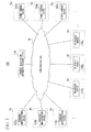
- Fig. 1 is a diagram illustrating an example of a use environment of a charging infrastructure information providing system 100 according to an embodiment.
- the charging infrastructure information providing system 100 it is assumed that there are a plurality of charging infrastructures Sa, Sb, Sc, etc. (hereinafter generically referred to as charging infrastructures S), a plurality of power companies Ea, Eb, Ec, etc. (hereinafter generically referred to as power companies E), and a plurality of electric vehicles Va, Vb, Vc, etc. (hereinafter generically referred to as electric vehicles V).
- the charging infrastructure information providing system 100 is a system that provides information regarding the charging infrastructures S to users of the electric vehicles V.
- the charging infrastructure information providing system 100 preferentially provides the users of the electric vehicles V with the information regarding the charging infrastructure S making a considerable contribution to supply of power of a predetermined attribute.
- the attribute refers to, for example, information indicating by which power generation method the power is generated.
- the power generation method is broadly classified into a power generation method using renewable energy and a power generation method using exhaustible energy. Examples of the renewable energy include energies of wind power, solar light, hydraulic power, a biomass, and the like.
- the exhaustible energy examples include energies of petroleum, natural gas, oil sands, methane hydrate, uranium, and the like.
- the contribution refers to an action of preferentially employing power of a predetermined attribute by the charging infrastructure S.
- the contribution refers to an action of preferentially employing energy with a low environment load as in renewable energy instead of exhaustible energy.
- the charging infrastructure information providing system 100 includes a charging infrastructure information providing device 110 and a plurality of charging infrastructure devices 130a, 130b, 130c, etc. (hereinafter generically referred to as charging infrastructure devices 130).
- the charging infrastructure information providing device 110 and each charging infrastructure device 130 are connected to a communication line N.
- a plurality of power company devices 150a, 150b, 150c, etc. hereinafter generically referred to as power company devices 150
- a plurality of on-vehicle devices 170a, 170b, 170c, etc. (hereinafter generically referred to as on-vehicle devices 170) are connected to the communication line N.
- the communication line N includes computer networks such as the Internet, core networks of communication operators, and various local networks.
- the on-vehicle device 170 may be an example of a "user terminal of a user" in the present invention.
- the charging infrastructure information providing device 110 is a device that provides the information regarding the charging infrastructures S to the users of the electric vehicles V. More specifically, the charging infrastructure information providing device 110 receives power-feed data transmitted from each charging infrastructure device 130.
- the power-feed data includes information regarding an amount of power fed from a charger of the charging infrastructure S to the electric vehicle V and attribute information of the power. Further, the charging infrastructure information providing device 110 sequentially stores the information regarding the amount of power and the attribute information included in the power-feed data received from the charging infrastructure devices 130 in a power-feed information database in association therewith. Furthermore, the charging infrastructure information providing device 110 evaluates a contribution to supply of the power of the predetermined attribute in each charging infrastructure S based on the information stored in the power-feed information database.
- an evaluation method of referring to the absolute values of supply amounts of the power of predetermined attributes or an evaluation method of referring to relative values of the supply amounts of the power of the predetermined attributes is considered.
- the evaluation method of referring to the absolute values for example, when the charging station Sa supplies 10 (kW) of power of a predetermined attribute and the charging station Sb supplies 20 (kW) of power of a predetermined attribute, the charging station Sb is evaluated as making a greater contribution to the supply of the power of the predetermined attribute than the charging station Sa.
- the charging station Sa supplies 100 (kW) of power of various attributes and supplies 10 (kW) of power of a predetermined attribute among the power of the various attributes and the charging station Sb supplies 400 (kW) of power of various attributes and supplies 20 (kW) of power of a predetermined attribute among the power of the various attributes
- a ratio of the power of the predetermined attribute supplied by the charging infrastructure Sa to the power of the various attributes is 10 (%) and a ratio of the power of the predetermined attribute supplied by the charging infrastructure Sb is 5 (%). Accordingly, the charging station Sa is evaluated as making a greater contribution to the supply of the power of the predetermined attribute than the charging station Sb.
- the charging infrastructure information providing device 110 preferentially provides the on-vehicle devices 170 of the users of the electric vehicles V with the information regarding the charging infrastructure S making the considerable contribution to the supply of the power of the predetermined attribute.
- the power-feed information database may be an example of a "power-feed information storage unit" in the present invention.
- the charging infrastructure device 130 is a device that is installed in the charging infrastructure S and manages information regarding power fed from a charger of the charging infrastructure S to an electric vehicle. More specifically, a commercial power supply or a power supply for a charger of a solar light generation system, a storage cell, or the like is assumed to be installed in the charging infrastructure S. Also, operators of the charging infrastructures S are assumed to purchase system power generated by the contracted power companies E. Further, the purchased system power is assumed to be supplied to a charger via a commercial power supply. Also, a storage cell is assumed to be charged with power generated by a solar light generation system. Further, the power discharged from a storage cell is supplied to a charger.
- a charger is assumed to be supplied with system power from a commercial power supply or to be supplied with power from a storage cell.
- the charging infrastructure device 130 acquires data indicating attribute information of the system power supplied from the commercial power supply to the charger.
- the attribute information of the system power is, for example, assumed to be provided from the power company device 150 of each power company E.
- the charging infrastructure device 130 transmits power-feed data including an amount of power fed to the electric vehicle and the attribute information of the power indicated by data received from the power company device 150 to the charging infrastructure information providing device 110.
- the charging infrastructure device 130 when a solar light generation system and a storage cell are installed in the charging infrastructure S, the charging infrastructure device 130 generates attribute information of power generated by the solar light generation system. Further, when the power supplied from the storage cell to a charger is fed to an electric vehicle, the charging infrastructure device 130 transmits power-feed data including an amount of power fed to the electric vehicle and the attribute information of the generated power to the charging infrastructure information providing device 110. Also, the solar light generation system and the storage cell may be examples of "dispersed generation" in the present invention.
- the power company device 150 is a device that is operated by each power company E. More specifically, the power company device 150 is a device that provides attribute information of system power supplied by the power company E.
- the on-vehicle device 170 is a device that is mounted on the electric vehicle V. More specifically, the on-vehicle device 170 is provided with information regarding the charging infrastructure S from the charging infrastructure information providing device 110.
- the charging infrastructure information providing system 100 including one charging infrastructure information providing device 110 will be described.
- the charging infrastructure information providing system 104 may include a plurality of charging infrastructure information providing devices 110.
- Fig. 2 is a diagram illustrating an example of a block configuration of the charging infrastructure information providing device 110.
- the charging infrastructure information providing device 110 includes a power-feed data reception unit 111, a contribution evaluation unit 112, a charging infrastructure information providing unit 113, a power-feed information storage unit 114, and a charging infrastructure information storage unit 115.
- a function and an operation of each constituent element will be described.
- the power-feed data reception unit 111 receives the power-feed data transmitted from each of the charging infrastructure devices 130.
- the contribution evaluation unit 112 evaluates a contribution to the supply of the power of the predetermined attribute in each charging infrastructure S based on the information regarding the amount of power fed to the electric vehicle V in each charging infrastructure S and the attribute information of the power in each charging infrastructure S. More specifically, the contribution evaluation unit 112 evaluates a contribution to the supply of the power of the predetermined attribute in each charging infrastructure S based on the information stored in the power-feed information storage unit 114.
- the charging infrastructure information providing unit 113 preferentially provides the on-vehicle device 170 of the electric vehicle V with the information regarding the charging infrastructure S making the considerable contribution to the supply of the power of the predetermined attribute. More specifically, the charging infrastructure information providing unit 113 preferentially provides the information regarding the charging infrastructure S making the considerable contribution to the supply of the power of the predetermined attribute based on the result evaluated by the contribution evaluation unit 112.
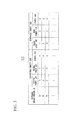
- Fig. 3 is a diagram illustrating an example of the information stored in the power feed information storage unit 114 in a table form.
- the power feed information storage unit 114 stores information regarding each of charging infrastructure identifiers (IDs), exhaustible energy (kW), and renewable energy (kW) in association therewith.
- IDs charging infrastructure identifiers
- kW exhaustible energy
- kW renewable energy
- information regarding each of nuclear power (kW), thermal power (kW), and others (kW) is stored in association therewith.
- renewable energy (kW) information regarding each of solar light (kW), wind power (kW), and others (kW) is stored in association therewith.
- the charging infrastructure ID is an identification code for uniquely identifying each charging infrastructure S.
- the nuclear power (kW) is information regarding an amount of power generated by nuclear power generation among the amounts of power supplied to the electric vehicle V during a predetermined period in the charging infrastructure S identified by the charging infrastructure ID.
- the thermal power (kW) is information regarding an amount of power generated by the thermal power generation among the amounts of power supplied to the electric vehicle V during a predetermined period in the charging infrastructure S identified by the charging infrastructure ID.
- the others (kW) of the exhaustible energy (kW) is information regarding amounts of power generated by power generation methods using exhaustible energy other than the nuclear power generation and the thermal power generation among the amounts of power supplied to the electric vehicle V during a predetermined period in the charging infrastructure S identified by the charging infrastructure ID.
- the solar light (kW) is information regarding an amount of power generated by the solar light generation among the amounts of power supplied to the electric vehicle V during a predetermined period in the charging infrastructure S identified by the charging infrastructure ID.
- the wind power (kW) is information regarding an amount of power generated by the wind power generation among the amounts of power supplied to the electric vehicle V during a predetermined period in the charging infrastructure S identified by the charging infrastructure ID.
- the others (kW) of the renewable energy (kW) are information regarding amounts of power generated by power generation methods using renewable energy other than the solar light generation and the wind power generation among the amounts of power supplied to the electric vehicle V during a predetermined period in the charging infrastructure S identified by the charging infrastructure ID.
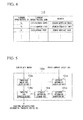
- Fig. 4 is a diagram illustrating an example of the information stored in the charging infrastructure information storage unit 115 in a table form.
- the charging infrastructure information storage unit 115 stores information regarding each of charging infrastructure IDs, charging infrastructure names, and addresses in association therewith.
- the charging infrastructure ID is an identification code for uniquely identifying each charging infrastructure S.
- the charging infrastructure name is the name of the charging infrastructure S identified by the charging infrastructure ID.
- the address is a location of the charging infrastructure S identified by the charging infrastructure ID.
- Fig. 5 is a diagram illustrating an example of a block configuration of the charging infrastructure device 130a.
- the charging infrastructure device 130a includes an attribute information acquisition unit 131a, an attribute information generation unit 132a, a power-feed amount data reception unit 133a, a power-feed data transmission unit 134a, and an attribute information storage unit 135a.
- the charging infrastructure devices 130b, 130c, etc. other than the charging infrastructure device 130a also include the same constituent elements as the constituent elements included in the charging infrastructure device 130a.
- the same suffix (a, b, c, etc.) as that of the charging infrastructure device 130 including each constituent element is suffixed to each constituent element to distinguish the constituent element from the other constituent elements.
- the attribute information acquisition unit 131a, an attribute information acquisition unit 131b, and an attribute information acquisition unit 131c indicate the constituent elements of the charging infrastructure device 130a, the charging infrastructure device 130b, and the charging infrastructure device 130c, respectively.
- a function and an operation of the constituent element with no suffix indicates a function and an operation of any constituent element with the same number.
- a function and an operation described with regard to the attribute information acquisition unit 131 indicate functions and operations of the attribute information acquisition unit 131a, the attribute information acquisition unit 131b, the attribute information acquisition unit 131c, etc.
- a function and an operation of each constituent element will be described.
- the attribute information acquisition unit 131 acquires attribute information regarding power supplied from a commercial power supply and a charger installed in the charging infrastructure S.
- the attribute information generation unit 132 generates attribute information regarding the power generated by a solar light generation system installed in the charging infrastructure S and supplied from the storage cell to the charger.
- the power-feed amount data reception unit 133 receives data indicating an amount of power fed from the commercial power supply to the charger, from an electricity meter. Also, the power-feed amount data reception unit 133 receives data indicating the amount of power fed from the storage cell to the charger from the electricity meter.
- the power-feed data transmission unit 134 transmits power-feed data including information regarding an amount of power fed from the charger to an electric vehicle and attribute information regarding the power to the charging infrastructure information providing device 110. More specifically, when the power supplied from the commercial power supply to the charger is fed to the electric vehicle V, the power-feed data transmission unit 134 transmits power-feed data including information regarding an amount of power fed to the electric vehicle V and attribute information regarding the power acquired by the attribute information acquisition unit 131. Also, when power generated by the solar light generation system and supplied from the storage cell to the charger is fed the electric vehicle V, the power-feed data transmission unit 134 transmits power-feed data including information regarding an amount of power fed to the electric vehicle V and attribute information of the power generated by the attribute information generation unit 132.
- Fig. 6 is a diagram illustrating an example of the information stored in the attribute information storage unit 135 in a table form.
- the attribute information storage unit 135 stores information regarding each of power, exhaustible energy (%), and renewable energy (%) in association therewith.
- the exhaustible energy (%) information regarding each of nuclear power (%), thermal power (%), and others (%) is be stored in association therewith.
- the renewable energy (%) information regarding each of solar light (%), wind power (%), and others (%) is stored in association therewith.
- the power supply is information indicating a power supply that supplies power to the charger.
- the nuclear power (%) is a ratio of power generated by nuclear power generation to the amount of power supplied from the power supply.
- the thermal power (%) is a ratio of power generated by thermal power generation to the amount of power supplied from the power supply.
- the others (%) of the exhaustible energy (%) are ratios of power generated by power generation methods using exhaustible energy other than the nuclear power generation and the thermal power generation to the amount of power supplied from the power supply.
- the solar light (%) is a ratio of power generated by solar light generation to the amount of power supplied from the power supply.
- the wind power (%) is a ratio of power generated by wind power generation to the amount of power supplied from the power supply.
- the others (%) of the renewable energy (%) are ratios of power generated by power generation methods using renewable energy other than the solar light generation and the wind power generation to the amount of power supplied from the power supply.
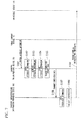
- Fig. 7 is a diagram illustrating an example of an operation sequence of the charging infrastructure information providing device 110, the charging infrastructure device 130, the power company device 150, and the on-vehicle device 170.
- This operation sequence represents operations of evaluating a contribution to supply of power of a predetermined attribute with reference to the absolute value of a supply amount of power generated by solar light generation and preferentially providing the on-vehicle device 170 of the electric vehicle V with information of the charging infrastructure S making a considerable contribution to the supply of the power generated by the solar light generation.
- FIGS. 1 to 6 are all referred to.
- a commercial power supply is assumed to be installed in the charging infrastructure S as a power supply. Further, the commercial power supply is assumed to be supplied with system power generated by the power companies E contracted with the operator of the charging infrastructure S. Furthermore, the attribute information of the system power generated by each power company E is assumed to be publicly available. For example, each power company E is assumed to allow the power company device 150 to release the attribute information of the system power it has generated to the World Wide Web (WWW). In this case, the attribute information acquisition unit 131 of the charging infrastructure device 130 acquires the attribute information of the system power released by the power company device 150 (S101).
- the attribute information of the system power is considered as information indicating a ratio of the amounts of power generated by each power generation method. Then, the attribute information acquisition unit 131 stores the acquired attribute information of the system power in the attribute information storage unit 135 (S102). Thus, the attribute information of the system power generated by the contracted power companies E and supplied from the commercial power supply to the charger is stored in the attribute information storage unit 135 of the charging infrastructure device 130, as illustrated in FIG. 6 .
- a solar light generation system and a storage cell are further installed as power supplies in the charging infrastructure S in some cases.
- the attribute information generation unit 132 of the charging infrastructure device 130 generates attribute information of the power generated by the solar light generation system and supplied from the storage cell to the charger (S103). For example, the attribute information generation unit 132 generates information indicating solar light generation 100 (%) as the attribute information of the power. Then, the attribute information generation unit 132 stores the generated attribute information of the power in the attribute information storage unit 13 5 (S104). Thus, the attribute information of the power generated by the solar light generation system and supplied from the storage cell to the charger is stored in the attribute information storage unit 135, as illustrated in FIG. 6 .
- the power fed from the charger to the electric vehicle V is supplied from the commercial power supply or the storage cell.
- a first electricity meter that measures an amount of power supplied from the commercial power supply to the charger and a second electricity meter that measures an amount of power supplied from the storage cell to the charger are assumed to be installed in the charging station S.
- the first electricity meter measures the amount of supplied power and transmits power-feed amount data indicating the measured value to the charging infrastructure device 130.
- the second electricity meter measures the amount of supplied power and transmits power-feed amount data indicating the measured value to the charging infrastructure device 130.
- the power-feed amount data reception unit 133 of the charging infrastructure device 130 receives the power-feed amount data transmitted from the first electricity meter or the second electricity meter (S105), the power-feed amount data reception unit 133 transmits data including information regarding the measured value of the amount of power indicated by the power-feed amount data and information indicating the electricity meter performing the measurement to the power-feed data transmission unit 134.
- the power-feed data transmission unit 134 of the charging infrastructure device 130 When the power-feed data transmission unit 134 of the charging infrastructure device 130 receives the data transmitted from the power-feed amount data reception unit 133, the power-feed data transmission unit 134 reads the information stored in the attribute information storage unit 135.
- the power-feed data transmission unit 134 when the data received from the power-feed amount data reception unit 133 includes information indicating that the electricity meter measuring the amount of power is the first electricity meter, the power-feed data transmission unit 134 reads the attribute information stored in association with the power supply "commercial power supply.” Also, when the data received from the power-feed amount data reception unit 133 includes information indicating that the electricity meter measuring the amount of power is the second electricity meter, the power-feed data transmission unit 134 reads the attribute information stored in association with the power supply "solar light generation system.” Then, the power-feed data transmission unit 134 transmits, to the charging infrastructure information providing device 110, power-feed data including the charging infrastructure ID, the information regarding the measured value of the amount of power included in the data received from the power-feed amount data reception unit 133, and the attribute information read from the attribute information storage unit 135 (S106).
- the charging infrastructure device 130 of each charging infrastructure S repeats the same processes as steps S101 to S106 described above.
- the power-feed data reception unit 111 of the charging infrastructure information providing device 110 receives the power-feed data transmitted from the charging infrastructure device 130, the power-feed data reception unit 111 stores the information regarding the amount of power fed to the electric vehicle V in the charging infrastructure S and the attribute information of the power in association therewith based on the information included in the power-feed data in the power-feed information storage unit 114 (S107).
- the power-feed data reception unit 111 stores values obtained by adding nuclear power “0 (kW),” thermal power “0 (kW),” and the others “0 (kW)” of the exhaustible energy, and solar light “10 (kW),” wind power “0 (kW),” and the others “0 (kW)” of the renewable energy to values of the respective information stored in association with the charging infrastructure ID "Sa” among the information stored in the power-feed information storage unit 114.
- the power-feed data reception unit 111 stores values obtained by adding nuclear power "0 (kW),” thermal power “0 (kW),” and the others “0 (kW)” of the exhaustible energy, and solar light “10 (kW),” wind power “0 (kW),” and the others “0 (kW)” of the renewable energy to values of the respective information stored in association with the charging infrastructure ID "Sa” among the information stored in the power-feed information storage unit 114.
- the contribution evaluation unit 112 of the charging infrastructure information providing device 110 evaluates the contribution to the supply of the power of the predetermined attribute in each charging infrastructure S based on the information stored in the power-feed information storage unit 114 (S108).
- the contribution evaluation unit 112 evaluates the contribution to the supply of the power generated by a power generation method using the renewable energy.
- the contribution evaluation unit 112 evaluates the absolute value of the solar light (kW) associated with each charging infrastructure ID. Then, the contribution evaluation unit 112 transmits, as the evaluation result, data indicating a predetermined number of charging infrastructure IDs to the charging infrastructure information providing unit 113 in order from the larger absolute value of the solar light (kW).
- the charging infrastructure information providing unit 113 of the charging infrastructure information providing device 110 receives the data transmitted from the contribution evaluation unit 112, the charging infrastructure information providing unit 113 reads the information stored in the charging infrastructure information storage unit 115. For example, the charging infrastructure information providing unit 113 reads the charging infrastructure name and the address stored in association with each charging infrastructure ID indicated by the data received by the contribution evaluation unit 112. Then, the charging infrastructure information providing unit 113 provides the read information to the on-vehicle device 170 by releasing the information to, for example, the WWW (S109).
- the WWW WWW
- the on-vehicle device 170 can acquire the information regarding the charging infrastructure S released by the charging infrastructure information providing device 110.
- the information regarding the charging infrastructure S making a considerable contribution to the supply of the power generated by the solar light generation is preferentially introduced.
- an increase in attraction of customers in the introduced charging infrastructure S can be expected. Accordingly, this can be predicted to encourage operators of the charging infrastructures S to actively supply the power generated by the solar light generation when they wish to introduce their charging infrastructures S to the users of the electric vehicles V.
- the charging infrastructure information providing system 100 can encourage the operators of the charging infrastructures S to actively supply the power of the predetermined attribute to the electric vehicles V
- Fig. 8 is a diagram illustrating an example of a hardware configuration when the charging infrastructure information providing device 110 and the charging infrastructure device 130 are configured by electronic information processing devices such as computers.
- the charging infrastructure information providing device 110 and the charging infrastructure device 130 include a central processing unit (CPU) peripheral unit, an input and output unit, and a legacy input and output unit.
- the CPU peripheral unit includes a CPU 802, a random access memory (RAM) 803, a graphic controller 804, and a display device 805 connected to each other by a host controller 801.
- the input and output unit includes a communication interface 807, a hard disk drive 808, and a compact disk read-only memory (CD-ROM) drive 809 connected to the host controller 801 by an input and output controller 806.
- the legacy input and output unit includes a read-only memory (ROM) 810, a flexible disk drive 811, and an input and output chip 812 connected to the input and output controller 806.
- the host controller 801 connects the RAM 803 to the CPU 802 and the graphic controller 804 accessing the RAM 803 at a high transmission rate.
- the CPU 802 operates based on programs stored in the RAM 810 and the RAM 803 and controls each unit.
- the graphic controller 804 acquires image data generated on a frame buffer formed in the RAM 803 by the CPU 802 or the like and displays the image data on the display device 805.
- the graphic controller 804 may include a frame buffer storing the image data generated by the CPU 802 or the like therein.
- the input and output controller 806 connects the host controller 801 to the communication interface 807, the CD-ROM drive 809, and the hard disk drive 808 which are relatively high speed input and output devices.
- the hard disk drive 808 stores a program and data used by the CPU 802.
- the communication interface 807 connects to a network communication device 891 to transmit and receive a program and data.
- the CD-ROM drive 809 reads a program or data from the CD-ROM 892 and provides the program or the data to the hard disk drive 808 and the communication interface 807 via the RAM 803.
- the ROM 810R and relatively low speed input and output devices of the flexible disk drive 811 and the input and output chip 812 are connected to the input and output controller 806.
- the ROM 810 stores, for example, boot programs executed at the time of activation of the charging infrastructure information providing device 110 and the charging infrastructure device 130 or a program dependent on hardware of the charging infrastructure information providing device 110 and the charging infrastructure device 130.
- the flexible disk drive 811 reads a program or data from a flexible disk 893 and provides the program or the data to the hard disk drive 808 and the communication interface 807 via the RAM 803.
- the input and output chip 812 connects various input and output devices via the flexible disk drive 811, a parallel port, a serial port, a keyboard port, a mouse port, or the like.
- a program executed by the CPU 802 is stored in a recording medium such as the flexible disk 893, the CD-ROM 892, an integrated circuit (IC) card, or the like to be provided to users.
- the program stored in the recording medium may or may not be compressed.
- the program is installed from the recording medium to the hard disk drive 808, is read to the RAM 803, and is executed by the CPU 802.
- the program executed by the CPU 802 causes the charging infrastructure information providing device 110 to function as the power-feed data reception unit 111, the contribution evaluation unit 112, the charging infrastructure information providing unit 113, the power-feed information storage unit 114, and the charging infrastructure information storage unit 115 described with reference to FIGS.
- the charging infrastructure device 130 causes the charging infrastructure device 130 to function as the attribute information acquisition unit 131, the attribute information generation unit 132, the power-feed amount data reception unit 133, the power-feed data transmission unit 134, and the attribute information storage unit 135 described with reference to FIGS. 1 to 7 .
- the above-described programs may be stored in an external storage medium.
- Examples of available storage media include not only the flexible disk 893 and the CD-ROM 892 but also an optical storage medium such as a digital versatile disk (DVD) or a phase disk (PD), a magneto-optical storage medium such as a mini disk (MD), a tape medium, and a semiconductor memory such as an IC card.
- a storage medium such as a hard disk or a RAM provided in a server system connected to a dedicated communication network or the Internet may be used as the storage medium and the above program may be provided as a program via a network.
- the present invention relates to a charging infrastructure information providing system configured to provide information regarding each charging infrastructure to users of electric vehicles. According to the present invention, it is possible to encourage operators of the charging infrastructures to actively supply power of a predetermined attribute to the electric vehicles.
Landscapes
- Engineering & Computer Science (AREA)
- Power Engineering (AREA)
- Transportation (AREA)
- Mechanical Engineering (AREA)
- Charge And Discharge Circuits For Batteries Or The Like (AREA)
- Electric Propulsion And Braking For Vehicles (AREA)
- Management, Administration, Business Operations System, And Electronic Commerce (AREA)
- Remote Monitoring And Control Of Power-Distribution Networks (AREA)
- Navigation (AREA)
Abstract
Description
- The present invention relates to a charging infrastructure information providing system, a charging infrastructure information providing device, a control method, and a program. In particular, the present invention relates to a charging infrastructure information providing system and a charging infrastructure information providing device that provide charging infrastructure information to users of electric vehicles, a control method of controlling the charging infrastructure information providing device, and a program for the charging infrastructure information providing device.
- Priority is claimed on Japanese Patent Application No.
2011-208969, filed September 26, 2011 - In recent years, the term "smart" has been frequently used as in "smart grids," "smart meters," "smart communities," and the like. From a perspective of the future of power networks which are social infrastructure systems in the real world, although star-type structures from large-scale power plants to factories, offices, and households have been built at present, distribution, two-way communication, and individualization are expected to progress rapidly due to the advancement and development of wind power generation, solar cells, fuel cells, and storage cells and global warming prevention policies for supporting the advancement and development thereof.
- The research and development disclosed in Non
Patent Literature 1 proposes an idea of energy informationization to aim for construction of a new ultra-distributed energy social infrastructure by integration of power networks and information networks. More specifically, the research and development disclosed inNon Patent Literature 1 proposes execution of energy management in consideration of not only quantitative energy saving but also a reduction in the amount of generated carbon dioxide by distinguishing powers of respective power supplies from each other when a plurality of power sources are installed in households. - "<University Research Trend> Energy Informationization: Integration of Power Network and Information Network" by Takashi Matsuyama, Cue: Kyoto University Research Information Repository by Department of Electrical Engineering Kyoto University in March, 2010, No. 23, p. 3 to 8
- According to the research and development disclosed in
Patent Literature 1, since the power from each power supply is supplied in association with information regarding this power supply, realization of various types of energy management in light of differences between the power supplies can be considered to be enabled by referring to the information. - However, the research and development disclosed in
Patent Literature 1 does not propose energy management realized due to a difference between the power supplies by setting a charging infrastructure of electric vehicles as a target. - According to an aspect of the present invention, there is provided a charging infrastructure information providing system providing information regarding charging infrastructures to a user of an electric vehicle. The charging infrastructure information providing system includes a charging infrastructure information providing device configured to provide the information regarding each charging infrastructure to the user of the electric vehicle. The charging infrastructure information providing device includes a charging infrastructure information providing unit configured to preferentially provide information regarding a charging infrastructure making a considerable contribution to supply of power of a predetermined attribute to a user terminal of the user of the electric vehicle.
- The charging infrastructure information providing device may further include a contribution evaluation unit configured to evaluate a contribution to supply of the power of the predetermined attribute in each charging infrastructure based on information regarding an amount of power fed to the electric vehicle in each charging infrastructure and attribute information of the power. The charging infrastructure information providing unit of the charging infrastructure information providing device may preferentially provide the information regarding the charging infrastructure making the considerable contribution to the supply of the power of the predetermined attribute based on a result evaluated by the contribution evaluation unit.
- The charging infrastructure information providing device may further include a power-feed information storage unit configured to sequentially store the information regarding the amount of power fed to the electric vehicle in each charging infrastructure and the attribute information of the power in association therewith. The contribution evaluation unit of the charging infrastructure information providing device may evaluate the contribution to the supply of the power of the predetermined attribute in each charging infrastructure based on the information stored in the power-feed information storage unit.
- The charging infrastructure information providing system may further include a plurality of charging infrastructure devices configured to be installed in the plurality of charging infrastructures, respectively, and manage information regarding power fed from a charger of the charging infrastructure to the electric vehicle. Each of the charging infrastructure devices may include a power-feed data transmission unit configured to transmit power-feed data including the information regarding the amount of power fed from the charger to the electric vehicle and attribute information of the power to the charging infrastructure information providing device. The charging infrastructure information providing device may further include a power-feed data reception unit that receives the power-feed data transmitted from each of the charging infrastructure devices. The power-feed information storage unit of the charging infrastructure information providing device may sequentially store the information regarding the amount of power and the attribute information included in the power-feed data received by the power-feed data reception unit in association therewith.
- Each of the charging infrastructure devices may further include an attribute information acquisition unit configured to acquire attribute information of power supplied from a commercial power supply installed in the charging infrastructure to the charger. When the power supplied from the commercial power supply to the charger is fed to the electric vehicle, the power-feed data transmission unit of each of the charging infrastructure devices may transmit power-feed data including information regarding an amount of power fed to the electric vehicle and the attribute information of the power acquired by the attribute information acquisition unit.
- Each of the charging infrastructure devices may further include an attribute information generation unit configured to generate attribute information of power supplied from distributed generation installed in the charging infrastructure to the charger. When the power supplied from the distributed generation to the charger is fed to the electric vehicle, the power-feed data transmission unit of each of the charging infrastructure devices may transmit power-feed data including information regarding an amount of power fed to the electric vehicle and the attribute information of the power generated by the attribute information generation unit.
- According to another aspect of the present invention, there is provided a charging infrastructure information providing device providing information regarding charging infrastructures to a user of an electric vehicle. The charging infrastructure information providing device includes a charging infrastructure information providing unit configured to preferentially provide information regarding a charging infrastructure making a considerable contribution to supply of power of a predetermined attribute to a user terminal of the user of the electric vehicle.
- According to still another aspect of the present invention, there is provided a control method of controlling a charging infrastructure information providing device providing information regarding charging infrastructures to a user of an electric vehicle. The control method includes preferentially providing information regarding a charging infrastructure making a considerable contribution to supply of power of a predetermined attribute to a user terminal of the user of the electric vehicle.
- According to further still another aspect of the present invention, there is provided a program for a charging infrastructure information providing device providing information regarding charging infrastructures to a user of an electric vehicle. The program causes the charging infrastructure information providing device to function as a charging infrastructure information providing unit configured to preferentially provide information regarding a charging infrastructure making a considerable contribution to supply of power of a predetermined attribute to a user terminal of the user of the electric vehicle.
- In Summary of Invention described above, all of the characteristics necessary for the present invention are not listed, but sub-combinations of the characteristic groups can also be realized as inventions.
- According to the present invention, as described above, it is possible to encourage operators of charging infrastructures to actively supply power of predetermined attributes to electric vehicles.
-
-
Fig. 1 is a diagram illustrating an example of a use environment of a charging infrastructureinformation providing system 100 according to an embodiment. -
Fig. 2 is a diagram illustrating an example of a block configuration of a charging infrastructureinformation providing device 110. -
Fig. 3 is a diagram illustrating an example of information stored in a power feedinformation storage unit 114 in a table form. -
Fig. 4 is a diagram illustrating an example of information stored in a charging infrastructureinformation storage unit 115 in a table form. -
Fig. 5 is a diagram illustrating an example of a block configuration of acharging infrastructure device 130a. -
Fig. 6 is a diagram illustrating an example of information stored in an attributeinformation storage unit 135 in a table form. -
Fig. 7 is a diagram illustrating an example of an operation sequence of the charging infrastructureinformation providing device 110, acharging infrastructure device 130, apower company device 150, and an on-vehicle device 170. -
Fig. 8 is a diagram illustrating an example of a hardware configuration when the charging infrastructureinformation providing device 110 and thecharging infrastructure device 130 are configured by electronic information processing devices such as computers. - Hereinafter, the present invention will be described according to embodiments of the present invention. Also, the following embodiments do not limit the present invention described in the scope of the claims. Further, all of the combinations of the characteristics to be described in the embodiments may not be said to be requisites for the solutions to problems in the present invention.
-
Fig. 1 is a diagram illustrating an example of a use environment of a charging infrastructureinformation providing system 100 according to an embodiment. In the use environment of the charging infrastructureinformation providing system 100, it is assumed that there are a plurality of charging infrastructures Sa, Sb, Sc, etc. (hereinafter generically referred to as charging infrastructures S), a plurality of power companies Ea, Eb, Ec, etc. (hereinafter generically referred to as power companies E), and a plurality of electric vehicles Va, Vb, Vc, etc. (hereinafter generically referred to as electric vehicles V). The charging infrastructureinformation providing system 100 is a system that provides information regarding the charging infrastructures S to users of the electric vehicles V. More specifically, the charging infrastructureinformation providing system 100 preferentially provides the users of the electric vehicles V with the information regarding the charging infrastructure S making a considerable contribution to supply of power of a predetermined attribute. Here, the attribute refers to, for example, information indicating by which power generation method the power is generated. The power generation method is broadly classified into a power generation method using renewable energy and a power generation method using exhaustible energy. Examples of the renewable energy include energies of wind power, solar light, hydraulic power, a biomass, and the like. - Examples of the exhaustible energy include energies of petroleum, natural gas, oil sands, methane hydrate, uranium, and the like. Also, the contribution refers to an action of preferentially employing power of a predetermined attribute by the charging infrastructure S. Specifically, the contribution refers to an action of preferentially employing energy with a low environment load as in renewable energy instead of exhaustible energy.
- The charging infrastructure
information providing system 100 includes a charging infrastructureinformation providing device 110 and a plurality ofcharging infrastructure devices information providing device 110 and each charginginfrastructure device 130 are connected to a communication line N. Also, a plurality ofpower company devices vehicle devices vehicle device 170 may be an example of a "user terminal of a user" in the present invention. - The charging infrastructure
information providing device 110 is a device that provides the information regarding the charging infrastructures S to the users of the electric vehicles V. More specifically, the charging infrastructureinformation providing device 110 receives power-feed data transmitted from each charginginfrastructure device 130. The power-feed data includes information regarding an amount of power fed from a charger of the charging infrastructure S to the electric vehicle V and attribute information of the power. Further, the charging infrastructureinformation providing device 110 sequentially stores the information regarding the amount of power and the attribute information included in the power-feed data received from thecharging infrastructure devices 130 in a power-feed information database in association therewith. Furthermore, the charging infrastructureinformation providing device 110 evaluates a contribution to supply of the power of the predetermined attribute in each charging infrastructure S based on the information stored in the power-feed information database. Here, as a contribution evaluation method, an evaluation method of referring to the absolute values of supply amounts of the power of predetermined attributes or an evaluation method of referring to relative values of the supply amounts of the power of the predetermined attributes is considered. In the evaluation method of referring to the absolute values, for example, when the charging station Sa supplies 10 (kW) of power of a predetermined attribute and the charging station Sb supplies 20 (kW) of power of a predetermined attribute, the charging station Sb is evaluated as making a greater contribution to the supply of the power of the predetermined attribute than the charging station Sa. On the other hand, in the evaluation method of referring to the relative values, for example, when the charging station Sa supplies 100 (kW) of power of various attributes and supplies 10 (kW) of power of a predetermined attribute among the power of the various attributes and the charging station Sb supplies 400 (kW) of power of various attributes and supplies 20 (kW) of power of a predetermined attribute among the power of the various attributes, a ratio of the power of the predetermined attribute supplied by the charging infrastructure Sa to the power of the various attributes is 10 (%) and a ratio of the power of the predetermined attribute supplied by the charging infrastructure Sb is 5 (%). Accordingly, the charging station Sa is evaluated as making a greater contribution to the supply of the power of the predetermined attribute than the charging station Sb. Further, based on the evaluation result, the charging infrastructureinformation providing device 110 preferentially provides the on-vehicle devices 170 of the users of the electric vehicles V with the information regarding the charging infrastructure S making the considerable contribution to the supply of the power of the predetermined attribute. Also, the power-feed information database may be an example of a "power-feed information storage unit" in the present invention. - The
charging infrastructure device 130 is a device that is installed in the charging infrastructure S and manages information regarding power fed from a charger of the charging infrastructure S to an electric vehicle. More specifically, a commercial power supply or a power supply for a charger of a solar light generation system, a storage cell, or the like is assumed to be installed in the charging infrastructure S. Also, operators of the charging infrastructures S are assumed to purchase system power generated by the contracted power companies E. Further, the purchased system power is assumed to be supplied to a charger via a commercial power supply. Also, a storage cell is assumed to be charged with power generated by a solar light generation system. Further, the power discharged from a storage cell is supplied to a charger. That is, a charger is assumed to be supplied with system power from a commercial power supply or to be supplied with power from a storage cell. When a commercial power supply is installed in the charging infrastructure S, thecharging infrastructure device 130 acquires data indicating attribute information of the system power supplied from the commercial power supply to the charger. The attribute information of the system power is, for example, assumed to be provided from thepower company device 150 of each power company E. Further, when the power supplied from the commercial power supply to the charger is fed to an electric vehicle, thecharging infrastructure device 130 transmits power-feed data including an amount of power fed to the electric vehicle and the attribute information of the power indicated by data received from thepower company device 150 to the charging infrastructureinformation providing device 110. Also, when a solar light generation system and a storage cell are installed in the charging infrastructure S, thecharging infrastructure device 130 generates attribute information of power generated by the solar light generation system. Further, when the power supplied from the storage cell to a charger is fed to an electric vehicle, thecharging infrastructure device 130 transmits power-feed data including an amount of power fed to the electric vehicle and the attribute information of the generated power to the charging infrastructureinformation providing device 110. Also, the solar light generation system and the storage cell may be examples of "dispersed generation" in the present invention. - The
power company device 150 is a device that is operated by each power company E. More specifically, thepower company device 150 is a device that provides attribute information of system power supplied by the power company E. - The on-
vehicle device 170 is a device that is mounted on the electric vehicle V. More specifically, the on-vehicle device 170 is provided with information regarding the charging infrastructure S from the charging infrastructureinformation providing device 110. - In the present embodiment, to avoid complication of description, a configuration of the charging infrastructure
information providing system 100 including one charging infrastructureinformation providing device 110 will be described. However, the charging infrastructureinformation providing system 104 may include a plurality of charging infrastructureinformation providing devices 110. -
Fig. 2 is a diagram illustrating an example of a block configuration of the charging infrastructureinformation providing device 110. The charging infrastructureinformation providing device 110 includes a power-feeddata reception unit 111, acontribution evaluation unit 112, a charging infrastructureinformation providing unit 113, a power-feedinformation storage unit 114, and a charging infrastructureinformation storage unit 115. Hereinafter, a function and an operation of each constituent element will be described. - The power-feed
data reception unit 111 receives the power-feed data transmitted from each of thecharging infrastructure devices 130. - The
contribution evaluation unit 112 evaluates a contribution to the supply of the power of the predetermined attribute in each charging infrastructure S based on the information regarding the amount of power fed to the electric vehicle V in each charging infrastructure S and the attribute information of the power in each charging infrastructure S. More specifically, thecontribution evaluation unit 112 evaluates a contribution to the supply of the power of the predetermined attribute in each charging infrastructure S based on the information stored in the power-feedinformation storage unit 114. - The charging infrastructure
information providing unit 113 preferentially provides the on-vehicle device 170 of the electric vehicle V with the information regarding the charging infrastructure S making the considerable contribution to the supply of the power of the predetermined attribute. More specifically, the charging infrastructureinformation providing unit 113 preferentially provides the information regarding the charging infrastructure S making the considerable contribution to the supply of the power of the predetermined attribute based on the result evaluated by thecontribution evaluation unit 112. -
Fig. 3 is a diagram illustrating an example of the information stored in the power feedinformation storage unit 114 in a table form. The power feedinformation storage unit 114 stores information regarding each of charging infrastructure identifiers (IDs), exhaustible energy (kW), and renewable energy (kW) in association therewith. Here, with regard to the exhaustible energy (kW), information regarding each of nuclear power (kW), thermal power (kW), and others (kW) is stored in association therewith. Also, with regard to the renewable energy (kW), information regarding each of solar light (kW), wind power (kW), and others (kW) is stored in association therewith. - The charging infrastructure ID is an identification code for uniquely identifying each charging infrastructure S. The nuclear power (kW) is information regarding an amount of power generated by nuclear power generation among the amounts of power supplied to the electric vehicle V during a predetermined period in the charging infrastructure S identified by the charging infrastructure ID. The thermal power (kW) is information regarding an amount of power generated by the thermal power generation among the amounts of power supplied to the electric vehicle V during a predetermined period in the charging infrastructure S identified by the charging infrastructure ID. The others (kW) of the exhaustible energy (kW) is information regarding amounts of power generated by power generation methods using exhaustible energy other than the nuclear power generation and the thermal power generation among the amounts of power supplied to the electric vehicle V during a predetermined period in the charging infrastructure S identified by the charging infrastructure ID. The solar light (kW) is information regarding an amount of power generated by the solar light generation among the amounts of power supplied to the electric vehicle V during a predetermined period in the charging infrastructure S identified by the charging infrastructure ID. The wind power (kW) is information regarding an amount of power generated by the wind power generation among the amounts of power supplied to the electric vehicle V during a predetermined period in the charging infrastructure S identified by the charging infrastructure ID. The others (kW) of the renewable energy (kW) are information regarding amounts of power generated by power generation methods using renewable energy other than the solar light generation and the wind power generation among the amounts of power supplied to the electric vehicle V during a predetermined period in the charging infrastructure S identified by the charging infrastructure ID.
-
Fig. 4 is a diagram illustrating an example of the information stored in the charging infrastructureinformation storage unit 115 in a table form. The charging infrastructureinformation storage unit 115 stores information regarding each of charging infrastructure IDs, charging infrastructure names, and addresses in association therewith. - The charging infrastructure ID is an identification code for uniquely identifying each charging infrastructure S. The charging infrastructure name is the name of the charging infrastructure S identified by the charging infrastructure ID. The address is a location of the charging infrastructure S identified by the charging infrastructure ID.
-
Fig. 5 is a diagram illustrating an example of a block configuration of thecharging infrastructure device 130a. Thecharging infrastructure device 130a includes an attributeinformation acquisition unit 131a, an attributeinformation generation unit 132a, a power-feed amountdata reception unit 133a, a power-feeddata transmission unit 134a, and an attributeinformation storage unit 135a. - The
charging infrastructure devices infrastructure device 130a also include the same constituent elements as the constituent elements included in thecharging infrastructure device 130a. In the following description, when the constituent elements included in thecharging infrastructure device 130 are distinguished from the constituent elements of the othercharging infrastructure devices 130, the same suffix (a, b, c, etc.) as that of thecharging infrastructure device 130 including each constituent element is suffixed to each constituent element to distinguish the constituent element from the other constituent elements. For example, the attributeinformation acquisition unit 131a, an attribute information acquisition unit 131b, and an attribute information acquisition unit 131c indicate the constituent elements of thecharging infrastructure device 130a, thecharging infrastructure device 130b, and thecharging infrastructure device 130c, respectively. - Also, in the following description, a function and an operation of the constituent element with no suffix indicates a function and an operation of any constituent element with the same number. For example, a function and an operation described with regard to the attribute information acquisition unit 131 indicate functions and operations of the attribute
information acquisition unit 131a, the attribute information acquisition unit 131b, the attribute information acquisition unit 131c, etc. Hereinafter, a function and an operation of each constituent element will be described. - The attribute information acquisition unit 131 acquires attribute information regarding power supplied from a commercial power supply and a charger installed in the charging infrastructure S.
- The attribute information generation unit 132 generates attribute information regarding the power generated by a solar light generation system installed in the charging infrastructure S and supplied from the storage cell to the charger.
- The power-feed amount data reception unit 133 receives data indicating an amount of power fed from the commercial power supply to the charger, from an electricity meter. Also, the power-feed amount data reception unit 133 receives data indicating the amount of power fed from the storage cell to the charger from the electricity meter.
- The power-feed data transmission unit 134 transmits power-feed data including information regarding an amount of power fed from the charger to an electric vehicle and attribute information regarding the power to the charging infrastructure
information providing device 110. More specifically, when the power supplied from the commercial power supply to the charger is fed to the electric vehicle V, the power-feed data transmission unit 134 transmits power-feed data including information regarding an amount of power fed to the electric vehicle V and attribute information regarding the power acquired by the attribute information acquisition unit 131. Also, when power generated by the solar light generation system and supplied from the storage cell to the charger is fed the electric vehicle V, the power-feed data transmission unit 134 transmits power-feed data including information regarding an amount of power fed to the electric vehicle V and attribute information of the power generated by the attribute information generation unit 132. -
Fig. 6 is a diagram illustrating an example of the information stored in the attributeinformation storage unit 135 in a table form. The attributeinformation storage unit 135 stores information regarding each of power, exhaustible energy (%), and renewable energy (%) in association therewith. With regard to the exhaustible energy (%), information regarding each of nuclear power (%), thermal power (%), and others (%) is be stored in association therewith. Also, with regard to the renewable energy (%), information regarding each of solar light (%), wind power (%), and others (%) is stored in association therewith. - The power supply is information indicating a power supply that supplies power to the charger. The nuclear power (%) is a ratio of power generated by nuclear power generation to the amount of power supplied from the power supply. The thermal power (%) is a ratio of power generated by thermal power generation to the amount of power supplied from the power supply. The others (%) of the exhaustible energy (%) are ratios of power generated by power generation methods using exhaustible energy other than the nuclear power generation and the thermal power generation to the amount of power supplied from the power supply. The solar light (%) is a ratio of power generated by solar light generation to the amount of power supplied from the power supply. The wind power (%) is a ratio of power generated by wind power generation to the amount of power supplied from the power supply. The others (%) of the renewable energy (%) are ratios of power generated by power generation methods using renewable energy other than the solar light generation and the wind power generation to the amount of power supplied from the power supply.
-
Fig. 7 is a diagram illustrating an example of an operation sequence of the charging infrastructureinformation providing device 110, thecharging infrastructure device 130, thepower company device 150, and the on-vehicle device 170. This operation sequence represents operations of evaluating a contribution to supply of power of a predetermined attribute with reference to the absolute value of a supply amount of power generated by solar light generation and preferentially providing the on-vehicle device 170 of the electric vehicle V with information of the charging infrastructure S making a considerable contribution to the supply of the power generated by the solar light generation. In this operation sequence,FIGS. 1 to 6 are all referred to. - A commercial power supply is assumed to be installed in the charging infrastructure S as a power supply. Further, the commercial power supply is assumed to be supplied with system power generated by the power companies E contracted with the operator of the charging infrastructure S. Furthermore, the attribute information of the system power generated by each power company E is assumed to be publicly available. For example, each power company E is assumed to allow the
power company device 150 to release the attribute information of the system power it has generated to the World Wide Web (WWW). In this case, the attribute information acquisition unit 131 of thecharging infrastructure device 130 acquires the attribute information of the system power released by the power company device 150 (S101). For example, when power generated by a plurality of kinds of power generation methods is mixed and supplied as system power, the attribute information of the system power is considered as information indicating a ratio of the amounts of power generated by each power generation method. Then, the attribute information acquisition unit 131 stores the acquired attribute information of the system power in the attribute information storage unit 135 (S102). Thus, the attribute information of the system power generated by the contracted power companies E and supplied from the commercial power supply to the charger is stored in the attributeinformation storage unit 135 of thecharging infrastructure device 130, as illustrated inFIG. 6 . - Also, a solar light generation system and a storage cell are further installed as power supplies in the charging infrastructure S in some cases. In this case, the attribute information generation unit 132 of the
charging infrastructure device 130 generates attribute information of the power generated by the solar light generation system and supplied from the storage cell to the charger (S103). For example, the attribute information generation unit 132 generates information indicating solar light generation 100 (%) as the attribute information of the power. Then, the attribute information generation unit 132 stores the generated attribute information of the power in the attribute information storage unit 13 5 (S104). Thus, the attribute information of the power generated by the solar light generation system and supplied from the storage cell to the charger is stored in the attributeinformation storage unit 135, as illustrated inFIG. 6 . - The power fed from the charger to the electric vehicle V is supplied from the commercial power supply or the storage cell. Here, a first electricity meter that measures an amount of power supplied from the commercial power supply to the charger and a second electricity meter that measures an amount of power supplied from the storage cell to the charger are assumed to be installed in the charging station S. When the power is supplied from the commercial power supply to the charger, the first electricity meter measures the amount of supplied power and transmits power-feed amount data indicating the measured value to the
charging infrastructure device 130. Likewise, when the power is supplied from the storage cell to the charger, the second electricity meter measures the amount of supplied power and transmits power-feed amount data indicating the measured value to thecharging infrastructure device 130. When the power-feed amount data reception unit 133 of thecharging infrastructure device 130 receives the power-feed amount data transmitted from the first electricity meter or the second electricity meter (S105), the power-feed amount data reception unit 133 transmits data including information regarding the measured value of the amount of power indicated by the power-feed amount data and information indicating the electricity meter performing the measurement to the power-feed data transmission unit 134. - When the power-feed data transmission unit 134 of the
charging infrastructure device 130 receives the data transmitted from the power-feed amount data reception unit 133, the power-feed data transmission unit 134 reads the information stored in the attributeinformation storage unit 135. - For example, when the data received from the power-feed amount data reception unit 133 includes information indicating that the electricity meter measuring the amount of power is the first electricity meter, the power-feed data transmission unit 134 reads the attribute information stored in association with the power supply "commercial power supply." Also, when the data received from the power-feed amount data reception unit 133 includes information indicating that the electricity meter measuring the amount of power is the second electricity meter, the power-feed data transmission unit 134 reads the attribute information stored in association with the power supply "solar light generation system." Then, the power-feed data transmission unit 134 transmits, to the charging infrastructure
information providing device 110, power-feed data including the charging infrastructure ID, the information regarding the measured value of the amount of power included in the data received from the power-feed amount data reception unit 133, and the attribute information read from the attribute information storage unit 135 (S106). - Whenever the power is fed to the electric vehicle V in the charging infrastructure S, the
charging infrastructure device 130 of each charging infrastructure S repeats the same processes as steps S101 to S106 described above. - Whenever the power-feed
data reception unit 111 of the charging infrastructureinformation providing device 110 receives the power-feed data transmitted from thecharging infrastructure device 130, the power-feeddata reception unit 111 stores the information regarding the amount of power fed to the electric vehicle V in the charging infrastructure S and the attribute information of the power in association therewith based on the information included in the power-feed data in the power-feed information storage unit 114 (S107). For example, when information regarding the charging infrastructure ID "Sa," an amount of power "10 (kW)," and solar light "100 (%)" is included in the power-feed data, the power-feeddata reception unit 111 stores values obtained by adding nuclear power "0 (kW)," thermal power "0 (kW)," and the others "0 (kW)" of the exhaustible energy, and solar light "10 (kW)," wind power "0 (kW)," and the others "0 (kW)" of the renewable energy to values of the respective information stored in association with the charging infrastructure ID "Sa" among the information stored in the power-feedinformation storage unit 114. Thus, whenever power is fed to the electric vehicle V in the charging infrastructure S, the information regarding the amount of power of each attribute fed in this charging infrastructure S is integrated and stored in the power-feedinformation storage unit 114. - Thus, when the information stored in the power-feed
information storage unit 114 is updated, thecontribution evaluation unit 112 of the charging infrastructureinformation providing device 110 evaluates the contribution to the supply of the power of the predetermined attribute in each charging infrastructure S based on the information stored in the power-feed information storage unit 114 (S108). In the case of this example, thecontribution evaluation unit 112 evaluates the contribution to the supply of the power generated by a power generation method using the renewable energy. In the case of this example, thecontribution evaluation unit 112 evaluates the absolute value of the solar light (kW) associated with each charging infrastructure ID. Then, thecontribution evaluation unit 112 transmits, as the evaluation result, data indicating a predetermined number of charging infrastructure IDs to the charging infrastructureinformation providing unit 113 in order from the larger absolute value of the solar light (kW). - When the charging infrastructure
information providing unit 113 of the charging infrastructureinformation providing device 110 receives the data transmitted from thecontribution evaluation unit 112, the charging infrastructureinformation providing unit 113 reads the information stored in the charging infrastructureinformation storage unit 115. For example, the charging infrastructureinformation providing unit 113 reads the charging infrastructure name and the address stored in association with each charging infrastructure ID indicated by the data received by thecontribution evaluation unit 112. Then, the charging infrastructureinformation providing unit 113 provides the read information to the on-vehicle device 170 by releasing the information to, for example, the WWW (S109). - Thus, the on-
vehicle device 170 can acquire the information regarding the charging infrastructure S released by the charging infrastructureinformation providing device 110. Depending on the information, the information regarding the charging infrastructure S making a considerable contribution to the supply of the power generated by the solar light generation is preferentially introduced. Of course, an increase in attraction of customers in the introduced charging infrastructure S can be expected. Accordingly, this can be predicted to encourage operators of the charging infrastructures S to actively supply the power generated by the solar light generation when they wish to introduce their charging infrastructures S to the users of the electric vehicles V. - As described above, the charging infrastructure
information providing system 100 can encourage the operators of the charging infrastructures S to actively supply the power of the predetermined attribute to the electric vehicles V -
Fig. 8 is a diagram illustrating an example of a hardware configuration when the charging infrastructureinformation providing device 110 and thecharging infrastructure device 130 are configured by electronic information processing devices such as computers. The charging infrastructureinformation providing device 110 and thecharging infrastructure device 130 include a central processing unit (CPU) peripheral unit, an input and output unit, and a legacy input and output unit. The CPU peripheral unit includes aCPU 802, a random access memory (RAM) 803, agraphic controller 804, and adisplay device 805 connected to each other by ahost controller 801. The input and output unit includes acommunication interface 807, ahard disk drive 808, and a compact disk read-only memory (CD-ROM) drive 809 connected to thehost controller 801 by an input andoutput controller 806. The legacy input and output unit includes a read-only memory (ROM) 810, aflexible disk drive 811, and an input andoutput chip 812 connected to the input andoutput controller 806. - The
host controller 801 connects theRAM 803 to theCPU 802 and thegraphic controller 804 accessing theRAM 803 at a high transmission rate. TheCPU 802 operates based on programs stored in theRAM 810 and theRAM 803 and controls each unit. Thegraphic controller 804 acquires image data generated on a frame buffer formed in theRAM 803 by theCPU 802 or the like and displays the image data on thedisplay device 805. Instead, thegraphic controller 804 may include a frame buffer storing the image data generated by theCPU 802 or the like therein. - The input and
output controller 806 connects thehost controller 801 to thecommunication interface 807, the CD-ROM drive 809, and thehard disk drive 808 which are relatively high speed input and output devices. Thehard disk drive 808 stores a program and data used by theCPU 802. Thecommunication interface 807 connects to anetwork communication device 891 to transmit and receive a program and data. The CD-ROM drive 809 reads a program or data from the CD-ROM 892 and provides the program or the data to thehard disk drive 808 and thecommunication interface 807 via theRAM 803. - The ROM 810R and relatively low speed input and output devices of the
flexible disk drive 811 and the input andoutput chip 812 are connected to the input andoutput controller 806. TheROM 810 stores, for example, boot programs executed at the time of activation of the charging infrastructureinformation providing device 110 and thecharging infrastructure device 130 or a program dependent on hardware of the charging infrastructureinformation providing device 110 and thecharging infrastructure device 130. Theflexible disk drive 811 reads a program or data from aflexible disk 893 and provides the program or the data to thehard disk drive 808 and thecommunication interface 807 via theRAM 803. The input andoutput chip 812 connects various input and output devices via theflexible disk drive 811, a parallel port, a serial port, a keyboard port, a mouse port, or the like. - A program executed by the
CPU 802 is stored in a recording medium such as theflexible disk 893, the CD-ROM 892, an integrated circuit (IC) card, or the like to be provided to users. The program stored in the recording medium may or may not be compressed. The program is installed from the recording medium to thehard disk drive 808, is read to theRAM 803, and is executed by theCPU 802. The program executed by theCPU 802 causes the charging infrastructureinformation providing device 110 to function as the power-feeddata reception unit 111, thecontribution evaluation unit 112, the charging infrastructureinformation providing unit 113, the power-feedinformation storage unit 114, and the charging infrastructureinformation storage unit 115 described with reference toFIGS. 1 to 7 and causes thecharging infrastructure device 130 to function as the attribute information acquisition unit 131, the attribute information generation unit 132, the power-feed amount data reception unit 133, the power-feed data transmission unit 134, and the attributeinformation storage unit 135 described with reference toFIGS. 1 to 7 . - The above-described programs may be stored in an external storage medium. Examples of available storage media include not only the
flexible disk 893 and the CD-ROM 892 but also an optical storage medium such as a digital versatile disk (DVD) or a phase disk (PD), a magneto-optical storage medium such as a mini disk (MD), a tape medium, and a semiconductor memory such as an IC card. Also, a storage medium such as a hard disk or a RAM provided in a server system connected to a dedicated communication network or the Internet may be used as the storage medium and the above program may be provided as a program via a network. - The preferred embodiments of the present invention have been described above, but the present invention is not limited to the foregoing embodiments. Additions, omissions, substitutions, and other changes of the configuration can be made without departing from the gist of the present invention. The present invention is not limited to the above description and is limited only by the appended claims.
- The present invention relates to a charging infrastructure information providing system configured to provide information regarding each charging infrastructure to users of electric vehicles. According to the present invention, it is possible to encourage operators of the charging infrastructures to actively supply power of a predetermined attribute to the electric vehicles.
-
- 100 Charging infrastructure information providing system
- 110 Charging infrastructure information providing device
- 111 Power-feed data reception unit
- 112 Contribution evaluation unit
- 113 Charging infrastructure information providing unit
- 114 Power-feed information storage unit
- 115 Charging infrastructure information storage unit
- 130 Charging infrastructure device
- 131 Attribute information acquisition unit
- 132 Attribute information generation unit
- 133 Power-feed amount data reception unit
- 134 Power-feed data transmission unit
- 135 Attribute information storage unit
- 150 Power company device
- 170 On-vehicle device
- 801 Host controller
- 802 CPU
- 803 RAM
- 804 Graphic controller
- 805 Display device
- 806 Input and output controller
- 807 Communication interface
- 808 Hard disk drive
- 809 CD-ROM drive
- 810 ROM
- 811 Flexible disk drive
- 812 Input and output chip
- 891 Network communication device
- 892 CD-ROM
- 893 Flexible disk
- E Power company
- N Communication line
- S Charging infrastructure
- V Electric vehicle
Claims (9)
- A charging infrastructure information providing system providing information regarding charging infrastructures to a user of an electric vehicle, the charging infrastructure information providing system comprising:a charging infrastructure information providing device configured to provide the information regarding each charging infrastructure to the user of the electric vehicle,wherein the charging infrastructure information providing device includes a charging infrastructure information providing unit configured to preferentially provide information regarding a charging infrastructure making a considerable contribution to supply of power of a predetermined attribute to a user terminal of the user of the electric vehicle.
- The charging infrastructure information providing system according to claim 1,
wherein the charging infrastructure information providing device further includes a contribution evaluation unit configured to evaluate a contribution to supply of the power of the predetermined attribute in each charging infrastructure based on information regarding an amount of power fed to the electric vehicle in each charging infrastructure and attribute information of the power, and
wherein the charging infrastructure information providing unit of the charging infrastructure information providing device preferentially provides the information regarding the charging infrastructure making the considerable contribution to the supply of the power of the predetermined attribute based on a result evaluated by the contribution evaluation unit. - The charging infrastructure information providing system according to claim 2,
wherein the charging infrastructure information providing device further includes a power-feed information storage unit configured to sequentially store the information regarding the amount of power fed to the electric vehicle in each charging infrastructure and the attribute information of the power in association therewith, and
wherein the contribution evaluation unit of the charging infrastructure information providing device evaluates the contribution to the supply of the power of the predetermined attribute in each charging infrastructure based on the information stored in the power-feed information storage unit. - The charging infrastructure information providing system according to claim 3, further comprising:a plurality of charging infrastructure devices configured to be installed in the plurality of charging infrastructures, respectively, and manage information regarding power fed from a charger of the charging infrastructure to the electric vehicle,wherein each of the charging infrastructure devices includes a power-feed data transmission unit configured to transmit power-feed data including the information regarding the amount of power fed from the charger to the electric vehicle and attribute information of the power to the charging infrastructure information providing device,wherein the charging infrastructure information providing device further includes a power-feed data reception unit that receives the power-feed data transmitted from each of the charging infrastructure devices, andwherein the power-feed information storage unit of the charging infrastructure information providing device sequentially stores the information regarding the amount of power and the attribute information included in the power-feed data received by the power-feed data reception unit in association therewith.
- The charging infrastructure information providing system according to claim 4,
wherein each of the charging infrastructure devices further includes an attribute information acquisition unit configured to acquire attribute information of power supplied from a commercial power supply installed in the charging infrastructure to the charger, and
wherein, when the power supplied from the commercial power supply to the charger is fed to the electric vehicle, the power-feed data transmission unit of each of the charging infrastructure devices transmits power-feed data including information regarding an amount of power fed to the electric vehicle and the attribute information of the power acquired by the attribute information acquisition unit. - The charging infrastructure information providing system according to claim 4,
wherein each of the charging infrastructure devices further includes an attribute information generation unit configured to generate attribute information of power supplied from distributed generation installed in the charging infrastructure to the charger, and
wherein, when the power supplied from the distributed generation to the charger is fed to the electric vehicle, the power-feed data transmission unit of each of the charging infrastructure devices transmits power-feed data including information regarding an amount of power fed to the electric vehicle and the attribute information of the power generated by the attribute information generation unit. - A charging infrastructure information providing device providing information regarding charging infrastructures to a user of an electric vehicle, the charging infrastructure information providing device comprising:a charging infrastructure information providing unit configured to preferentially provide information regarding a charging infrastructure making a considerable contribution to supply of power of a predetermined attribute to a user terminal of the user of the electric vehicle.
- A control method of controlling a charging infrastructure information providing device providing information regarding charging infrastructures to a user of an electric vehicle, the control method comprising:preferentially providing information regarding a charging infrastructure making a considerable contribution to supply of power of a predetermined attribute to a user terminal of the user of the electric vehicle.
- A program for a charging infrastructure information providing device providing information regarding charging infrastructures to a user of an electric vehicle, the program causing the charging infrastructure information providing device to function as a charging infrastructure information providing unit configured to preferentially provide information regarding a charging infrastructure making a considerable contribution to supply of power of a predetermined attribute to a user terminal of the user of the electric vehicle.
Applications Claiming Priority (2)
| Application Number | Priority Date | Filing Date | Title |
|---|---|---|---|
| JP2011208969A JP6109471B2 (en) | 2011-09-26 | 2011-09-26 | Charging infrastructure information providing system, charging infrastructure information providing apparatus, control method and program |
| PCT/JP2012/074527 WO2013047500A1 (en) | 2011-09-26 | 2012-09-25 | Charging infrastructure information providing system, charging infrastructure information providing device, control method and program |
Publications (3)
| Publication Number | Publication Date |
|---|---|
| EP2752812A1 true EP2752812A1 (en) | 2014-07-09 |
| EP2752812A4 EP2752812A4 (en) | 2016-03-30 |
| EP2752812B1 EP2752812B1 (en) | 2021-01-06 |
Family
ID=47995532
Family Applications (1)
| Application Number | Title | Priority Date | Filing Date |
|---|---|---|---|
| EP12837489.9A Active EP2752812B1 (en) | 2011-09-26 | 2012-09-25 | Charging infrastructure information providing system, charging infrastructure information providing device, control method and program |
Country Status (4)
| Country | Link |
|---|---|
| EP (1) | EP2752812B1 (en) |
| JP (1) | JP6109471B2 (en) |
| SG (1) | SG11201400822UA (en) |
| WO (1) | WO2013047500A1 (en) |
Cited By (2)
| Publication number | Priority date | Publication date | Assignee | Title |
|---|---|---|---|---|
| EP4084274A4 (en) * | 2019-12-27 | 2024-01-10 | Kyocera Corporation | POWER MANAGEMENT SYSTEM AND POWER MANAGEMENT METHOD |
| US12533979B2 (en) | 2021-07-16 | 2026-01-27 | Toyota Jidosha Kabushiki Kaisha | Computing device, vehicle system, and method |
Families Citing this family (2)
| Publication number | Priority date | Publication date | Assignee | Title |
|---|---|---|---|---|
| JP7172742B2 (en) * | 2019-03-04 | 2022-11-16 | トヨタ自動車株式会社 | Display device for charging system and display method for charging system |
| FI128774B (en) * | 2019-11-04 | 2020-11-30 | Liikennevirta Oy / Virta Ltd | Method and device for evaluating the reliability of charging station for electric vehicles |
Family Cites Families (13)
| Publication number | Priority date | Publication date | Assignee | Title |
|---|---|---|---|---|
| JP2001184406A (en) * | 1999-12-24 | 2001-07-06 | Sumitomo Corp | Power supply system and system relating to same, power supply operation method and method relating to same, computer-readable recording medium with program implementing same method recorded thereon |
| JP3780838B2 (en) * | 2000-09-26 | 2006-05-31 | 株式会社日立製作所 | Green power supply system and green power supply method |
| JP4501289B2 (en) * | 2001-02-26 | 2010-07-14 | トヨタ自動車株式会社 | Energy supply station guidance device |
| JP2006113890A (en) * | 2004-10-15 | 2006-04-27 | Fuji Heavy Ind Ltd | Electric vehicle management system |
| US20090066287A1 (en) * | 2006-08-10 | 2009-03-12 | V2Green, Inc. | Business Methods in a Power Aggregation System for Distributed Electric Resources |
| JP2008131841A (en) * | 2006-11-24 | 2008-06-05 | Central Res Inst Of Electric Power Ind | Renewable energy utilization method, renewable energy utilization system, and renewable energy information management apparatus |
| JP4365429B2 (en) * | 2007-07-24 | 2009-11-18 | トヨタ自動車株式会社 | Navigation device for displaying charging information and vehicle equipped with the device |
| AR074654A1 (en) * | 2008-10-01 | 2011-02-02 | Silver Spring Networks Inc | METHOD AND SYSTEM FOR APPLYING ENVIRONMENTAL INCENTIVES |
| JP2011102739A (en) * | 2009-11-10 | 2011-05-26 | Showa Shell Sekiyu Kk | Wide-area guide system of charging station for electric vehicle |
| JP2011109586A (en) * | 2009-11-20 | 2011-06-02 | Nec Corp | Mobile terminal and display method thereof |
| JP2011180008A (en) * | 2010-03-02 | 2011-09-15 | Aisin Aw Co Ltd | Navigation apparatus and program |
| JP2012226416A (en) * | 2011-04-15 | 2012-11-15 | Toyota Motor Corp | Charging system |
| WO2013024521A1 (en) * | 2011-08-12 | 2013-02-21 | トヨタ自動車株式会社 | Charging information-providing device |
-
2011
- 2011-09-26 JP JP2011208969A patent/JP6109471B2/en active Active
-
2012
- 2012-09-25 WO PCT/JP2012/074527 patent/WO2013047500A1/en not_active Ceased
- 2012-09-25 SG SG11201400822UA patent/SG11201400822UA/en unknown
- 2012-09-25 EP EP12837489.9A patent/EP2752812B1/en active Active
Cited By (2)
| Publication number | Priority date | Publication date | Assignee | Title |
|---|---|---|---|---|
| EP4084274A4 (en) * | 2019-12-27 | 2024-01-10 | Kyocera Corporation | POWER MANAGEMENT SYSTEM AND POWER MANAGEMENT METHOD |
| US12533979B2 (en) | 2021-07-16 | 2026-01-27 | Toyota Jidosha Kabushiki Kaisha | Computing device, vehicle system, and method |
Also Published As
| Publication number | Publication date |
|---|---|
| JP6109471B2 (en) | 2017-04-05 |
| WO2013047500A1 (en) | 2013-04-04 |
| JP2013069229A (en) | 2013-04-18 |
| EP2752812B1 (en) | 2021-01-06 |
| SG11201400822UA (en) | 2014-09-26 |
| EP2752812A4 (en) | 2016-03-30 |
Similar Documents
| Publication | Publication Date | Title |
|---|---|---|
| Ntombela et al. | A comprehensive review of the incorporation of electric vehicles and renewable energy distributed generation regarding smart grids | |
| Tayri et al. | Grid impacts of electric vehicle charging: A review of challenges and mitigation strategies | |
| Al-Shetwi et al. | Latest advancements in smart grid technologies and their transformative role in shaping the power systems of tomorrow: An overview | |
| Duan et al. | Data-driven distributionally robust energy-reserve-storage dispatch | |
| Chen et al. | Available transfer capability evaluation in a deregulated electricity market considering correlated wind power | |
| EP2752812B1 (en) | Charging infrastructure information providing system, charging infrastructure information providing device, control method and program | |
| JP7018558B2 (en) | Electric power trading system | |
| Mouftah et al. | Smart grid: networking, data management, and business models | |
| Meena et al. | Optimal accommodation and management of high renewable penetration in distribution systems | |
| Said et al. | Optimal design and analysis of a grid‐connected hybrid renewable energy system using HOMER Pro: A case study of Tumbatu Island, Zanzibar | |
| Ajewole et al. | Optimal component configuration and capacity sizing of a mini integrated power supply system | |
| EP4432206A1 (en) | Intermediary system, transaction system, and requesting method | |
| Kumar et al. | Smart grid management for smart city infrastructure using wearable sensors | |
| Mutule et al. | Development of smart grid standards in view of energy system functionalities | |
| EP3955415A1 (en) | Power management device, power management system, and power management method | |
| Rupolo et al. | Medium-and low-voltage planning of electric power distribution systems with distributed generation, energy storage sources, and electric vehicles | |
| JP6097476B2 (en) | Power information management system, power information management device, program, electric vehicle, charging infrastructure, housing and system module for electric vehicle | |
| PRETTICO et al. | Clean Energy Technology Observatory: Smart Grids in the European Union–2022 Status Report on Technology Development, Trends, Value Chains and Markets | |
| JP6893908B2 (en) | Charging infrastructure device | |
| Kanimozhi et al. | Transformation of smart grid to internet of energy | |
| Mahmud et al. | Rebound behaviour of uncoordinated EMS and their impact minimisation | |
| JP2017130220A (en) | Charging infrastructure, user terminal, on-vehicle device, and electric vehicle | |
| Afxentis et al. | Promotion of higher penetration of distributed PV through storage for all (StoRES) | |
| Amadi et al. | Evaluation of Losses in Distribution Networks of Selected Industrial Cities in Nigeria Using ETAP | |
| Alshammari et al. | Power system performance quality indices |
Legal Events
| Date | Code | Title | Description |
|---|---|---|---|
| PUAI | Public reference made under article 153(3) epc to a published international application that has entered the european phase |
Free format text: ORIGINAL CODE: 0009012 |
|
| 17P | Request for examination filed |
Effective date: 20140319 |
|
| AK | Designated contracting states |
Kind code of ref document: A1 Designated state(s): AL AT BE BG CH CY CZ DE DK EE ES FI FR GB GR HR HU IE IS IT LI LT LU LV MC MK MT NL NO PL PT RO RS SE SI SK SM TR |
|
| DAX | Request for extension of the european patent (deleted) | ||
| RA4 | Supplementary search report drawn up and despatched (corrected) |
Effective date: 20160229 |
|
| RIC1 | Information provided on ipc code assigned before grant |
Ipc: G01C 21/26 20060101ALI20160223BHEP Ipc: B60L 11/18 20060101ALI20160223BHEP Ipc: H02J 13/00 20060101ALI20160223BHEP Ipc: G06Q 50/10 20120101AFI20160223BHEP Ipc: H02J 7/00 20060101ALI20160223BHEP |
|
| STAA | Information on the status of an ep patent application or granted ep patent |
Free format text: STATUS: EXAMINATION IS IN PROGRESS |
|
| 17Q | First examination report despatched |
Effective date: 20190624 |
|
| REG | Reference to a national code |
Ref country code: DE Ref legal event code: R079 Ref document number: 602012074060 Country of ref document: DE Free format text: PREVIOUS MAIN CLASS: G06Q0050100000 Ipc: B60L0050500000 |
|
| RIC1 | Information provided on ipc code assigned before grant |
Ipc: B60L 50/50 20190101AFI20200720BHEP Ipc: H02J 7/00 20060101ALI20200720BHEP Ipc: G06Q 50/10 20120101ALI20200720BHEP Ipc: B60L 53/67 20190101ALI20200720BHEP Ipc: H02J 13/00 20060101ALI20200720BHEP Ipc: G01C 21/26 20060101ALI20200720BHEP Ipc: B60L 53/66 20190101ALI20200720BHEP |
|
| GRAP | Despatch of communication of intention to grant a patent |
Free format text: ORIGINAL CODE: EPIDOSNIGR1 |
|
| STAA | Information on the status of an ep patent application or granted ep patent |
Free format text: STATUS: GRANT OF PATENT IS INTENDED |
|
| INTG | Intention to grant announced |
Effective date: 20200916 |
|
| RIN1 | Information on inventor provided before grant (corrected) |
Inventor name: ISHII, SHINYA Inventor name: ONO, HIDEKAZU Inventor name: ADACHI, TETSUYA Inventor name: OWARI, NOBUYUKI |
|
| GRAS | Grant fee paid |
Free format text: ORIGINAL CODE: EPIDOSNIGR3 |
|
| GRAA | (expected) grant |
Free format text: ORIGINAL CODE: 0009210 |
|
| STAA | Information on the status of an ep patent application or granted ep patent |
Free format text: STATUS: THE PATENT HAS BEEN GRANTED |
|
| AK | Designated contracting states |
Kind code of ref document: B1 Designated state(s): AL AT BE BG CH CY CZ DE DK EE ES FI FR GB GR HR HU IE IS IT LI LT LU LV MC MK MT NL NO PL PT RO RS SE SI SK SM TR |
|
| REG | Reference to a national code |
Ref country code: GB Ref legal event code: FG4D |
|
| REG | Reference to a national code |
Ref country code: AT Ref legal event code: REF Ref document number: 1351986 Country of ref document: AT Kind code of ref document: T Effective date: 20210115 Ref country code: CH Ref legal event code: EP |
|
| REG | Reference to a national code |
Ref country code: DE Ref legal event code: R096 Ref document number: 602012074060 Country of ref document: DE |
|
| REG | Reference to a national code |
Ref country code: IE Ref legal event code: FG4D |
|
| REG | Reference to a national code |
Ref country code: NL Ref legal event code: MP Effective date: 20210106 |
|
| REG | Reference to a national code |
Ref country code: AT Ref legal event code: MK05 Ref document number: 1351986 Country of ref document: AT Kind code of ref document: T Effective date: 20210106 |
|
| REG | Reference to a national code |
Ref country code: LT Ref legal event code: MG9D |
|
| PG25 | Lapsed in a contracting state [announced via postgrant information from national office to epo] |
Ref country code: LT Free format text: LAPSE BECAUSE OF FAILURE TO SUBMIT A TRANSLATION OF THE DESCRIPTION OR TO PAY THE FEE WITHIN THE PRESCRIBED TIME-LIMIT Effective date: 20210106 Ref country code: PT Free format text: LAPSE BECAUSE OF FAILURE TO SUBMIT A TRANSLATION OF THE DESCRIPTION OR TO PAY THE FEE WITHIN THE PRESCRIBED TIME-LIMIT Effective date: 20210506 Ref country code: GR Free format text: LAPSE BECAUSE OF FAILURE TO SUBMIT A TRANSLATION OF THE DESCRIPTION OR TO PAY THE FEE WITHIN THE PRESCRIBED TIME-LIMIT Effective date: 20210407 Ref country code: FI Free format text: LAPSE BECAUSE OF FAILURE TO SUBMIT A TRANSLATION OF THE DESCRIPTION OR TO PAY THE FEE WITHIN THE PRESCRIBED TIME-LIMIT Effective date: 20210106 Ref country code: HR Free format text: LAPSE BECAUSE OF FAILURE TO SUBMIT A TRANSLATION OF THE DESCRIPTION OR TO PAY THE FEE WITHIN THE PRESCRIBED TIME-LIMIT Effective date: 20210106 Ref country code: BG Free format text: LAPSE BECAUSE OF FAILURE TO SUBMIT A TRANSLATION OF THE DESCRIPTION OR TO PAY THE FEE WITHIN THE PRESCRIBED TIME-LIMIT Effective date: 20210406 Ref country code: NL Free format text: LAPSE BECAUSE OF FAILURE TO SUBMIT A TRANSLATION OF THE DESCRIPTION OR TO PAY THE FEE WITHIN THE PRESCRIBED TIME-LIMIT Effective date: 20210106 Ref country code: NO Free format text: LAPSE BECAUSE OF FAILURE TO SUBMIT A TRANSLATION OF THE DESCRIPTION OR TO PAY THE FEE WITHIN THE PRESCRIBED TIME-LIMIT Effective date: 20210406 |
|
| PG25 | Lapsed in a contracting state [announced via postgrant information from national office to epo] |
Ref country code: PL Free format text: LAPSE BECAUSE OF FAILURE TO SUBMIT A TRANSLATION OF THE DESCRIPTION OR TO PAY THE FEE WITHIN THE PRESCRIBED TIME-LIMIT Effective date: 20210106 Ref country code: RS Free format text: LAPSE BECAUSE OF FAILURE TO SUBMIT A TRANSLATION OF THE DESCRIPTION OR TO PAY THE FEE WITHIN THE PRESCRIBED TIME-LIMIT Effective date: 20210106 Ref country code: LV Free format text: LAPSE BECAUSE OF FAILURE TO SUBMIT A TRANSLATION OF THE DESCRIPTION OR TO PAY THE FEE WITHIN THE PRESCRIBED TIME-LIMIT Effective date: 20210106 Ref country code: AT Free format text: LAPSE BECAUSE OF FAILURE TO SUBMIT A TRANSLATION OF THE DESCRIPTION OR TO PAY THE FEE WITHIN THE PRESCRIBED TIME-LIMIT Effective date: 20210106 Ref country code: SE Free format text: LAPSE BECAUSE OF FAILURE TO SUBMIT A TRANSLATION OF THE DESCRIPTION OR TO PAY THE FEE WITHIN THE PRESCRIBED TIME-LIMIT Effective date: 20210106 |
|
| PG25 | Lapsed in a contracting state [announced via postgrant information from national office to epo] |
Ref country code: IS Free format text: LAPSE BECAUSE OF FAILURE TO SUBMIT A TRANSLATION OF THE DESCRIPTION OR TO PAY THE FEE WITHIN THE PRESCRIBED TIME-LIMIT Effective date: 20210506 |
|
| REG | Reference to a national code |
Ref country code: DE Ref legal event code: R097 Ref document number: 602012074060 Country of ref document: DE |
|
| PG25 | Lapsed in a contracting state [announced via postgrant information from national office to epo] |
Ref country code: SM Free format text: LAPSE BECAUSE OF FAILURE TO SUBMIT A TRANSLATION OF THE DESCRIPTION OR TO PAY THE FEE WITHIN THE PRESCRIBED TIME-LIMIT Effective date: 20210106 Ref country code: EE Free format text: LAPSE BECAUSE OF FAILURE TO SUBMIT A TRANSLATION OF THE DESCRIPTION OR TO PAY THE FEE WITHIN THE PRESCRIBED TIME-LIMIT Effective date: 20210106 Ref country code: CZ Free format text: LAPSE BECAUSE OF FAILURE TO SUBMIT A TRANSLATION OF THE DESCRIPTION OR TO PAY THE FEE WITHIN THE PRESCRIBED TIME-LIMIT Effective date: 20210106 |
|
| PLBE | No opposition filed within time limit |
Free format text: ORIGINAL CODE: 0009261 |
|
| STAA | Information on the status of an ep patent application or granted ep patent |
Free format text: STATUS: NO OPPOSITION FILED WITHIN TIME LIMIT |
|
| PG25 | Lapsed in a contracting state [announced via postgrant information from national office to epo] |
Ref country code: RO Free format text: LAPSE BECAUSE OF FAILURE TO SUBMIT A TRANSLATION OF THE DESCRIPTION OR TO PAY THE FEE WITHIN THE PRESCRIBED TIME-LIMIT Effective date: 20210106 Ref country code: DK Free format text: LAPSE BECAUSE OF FAILURE TO SUBMIT A TRANSLATION OF THE DESCRIPTION OR TO PAY THE FEE WITHIN THE PRESCRIBED TIME-LIMIT Effective date: 20210106 Ref country code: ES Free format text: LAPSE BECAUSE OF FAILURE TO SUBMIT A TRANSLATION OF THE DESCRIPTION OR TO PAY THE FEE WITHIN THE PRESCRIBED TIME-LIMIT Effective date: 20210106 Ref country code: SK Free format text: LAPSE BECAUSE OF FAILURE TO SUBMIT A TRANSLATION OF THE DESCRIPTION OR TO PAY THE FEE WITHIN THE PRESCRIBED TIME-LIMIT Effective date: 20210106 |
|
| 26N | No opposition filed |
Effective date: 20211007 |
|
| PG25 | Lapsed in a contracting state [announced via postgrant information from national office to epo] |
Ref country code: AL Free format text: LAPSE BECAUSE OF FAILURE TO SUBMIT A TRANSLATION OF THE DESCRIPTION OR TO PAY THE FEE WITHIN THE PRESCRIBED TIME-LIMIT Effective date: 20210106 |
|
| PG25 | Lapsed in a contracting state [announced via postgrant information from national office to epo] |
Ref country code: SI Free format text: LAPSE BECAUSE OF FAILURE TO SUBMIT A TRANSLATION OF THE DESCRIPTION OR TO PAY THE FEE WITHIN THE PRESCRIBED TIME-LIMIT Effective date: 20210106 |
|
| PG25 | Lapsed in a contracting state [announced via postgrant information from national office to epo] |
Ref country code: IT Free format text: LAPSE BECAUSE OF FAILURE TO SUBMIT A TRANSLATION OF THE DESCRIPTION OR TO PAY THE FEE WITHIN THE PRESCRIBED TIME-LIMIT Effective date: 20210106 |
|
| REG | Reference to a national code |
Ref country code: CH Ref legal event code: PL |
|
| REG | Reference to a national code |
Ref country code: BE Ref legal event code: MM Effective date: 20210930 |
|
| GBPC | Gb: european patent ceased through non-payment of renewal fee |
Effective date: 20210925 |
|
| PG25 | Lapsed in a contracting state [announced via postgrant information from national office to epo] |
Ref country code: IS Free format text: LAPSE BECAUSE OF FAILURE TO SUBMIT A TRANSLATION OF THE DESCRIPTION OR TO PAY THE FEE WITHIN THE PRESCRIBED TIME-LIMIT Effective date: 20210506 Ref country code: MC Free format text: LAPSE BECAUSE OF FAILURE TO SUBMIT A TRANSLATION OF THE DESCRIPTION OR TO PAY THE FEE WITHIN THE PRESCRIBED TIME-LIMIT Effective date: 20210106 |
|
| PG25 | Lapsed in a contracting state [announced via postgrant information from national office to epo] |
Ref country code: LU Free format text: LAPSE BECAUSE OF NON-PAYMENT OF DUE FEES Effective date: 20210925 Ref country code: IE Free format text: LAPSE BECAUSE OF NON-PAYMENT OF DUE FEES Effective date: 20210925 Ref country code: GB Free format text: LAPSE BECAUSE OF NON-PAYMENT OF DUE FEES Effective date: 20210925 Ref country code: FR Free format text: LAPSE BECAUSE OF NON-PAYMENT OF DUE FEES Effective date: 20210930 Ref country code: BE Free format text: LAPSE BECAUSE OF NON-PAYMENT OF DUE FEES Effective date: 20210930 |
|
| PG25 | Lapsed in a contracting state [announced via postgrant information from national office to epo] |
Ref country code: LI Free format text: LAPSE BECAUSE OF NON-PAYMENT OF DUE FEES Effective date: 20210930 Ref country code: CH Free format text: LAPSE BECAUSE OF NON-PAYMENT OF DUE FEES Effective date: 20210930 |
|
| PG25 | Lapsed in a contracting state [announced via postgrant information from national office to epo] |
Ref country code: HU Free format text: LAPSE BECAUSE OF FAILURE TO SUBMIT A TRANSLATION OF THE DESCRIPTION OR TO PAY THE FEE WITHIN THE PRESCRIBED TIME-LIMIT; INVALID AB INITIO Effective date: 20120925 Ref country code: CY Free format text: LAPSE BECAUSE OF FAILURE TO SUBMIT A TRANSLATION OF THE DESCRIPTION OR TO PAY THE FEE WITHIN THE PRESCRIBED TIME-LIMIT Effective date: 20210106 |
|
| PG25 | Lapsed in a contracting state [announced via postgrant information from national office to epo] |
Ref country code: MK Free format text: LAPSE BECAUSE OF FAILURE TO SUBMIT A TRANSLATION OF THE DESCRIPTION OR TO PAY THE FEE WITHIN THE PRESCRIBED TIME-LIMIT Effective date: 20210106 |
|
| PG25 | Lapsed in a contracting state [announced via postgrant information from national office to epo] |
Ref country code: MT Free format text: LAPSE BECAUSE OF FAILURE TO SUBMIT A TRANSLATION OF THE DESCRIPTION OR TO PAY THE FEE WITHIN THE PRESCRIBED TIME-LIMIT Effective date: 20210106 |
|
| PGFP | Annual fee paid to national office [announced via postgrant information from national office to epo] |
Ref country code: DE Payment date: 20250730 Year of fee payment: 14 |
|
| PG25 | Lapsed in a contracting state [announced via postgrant information from national office to epo] |
Ref country code: TR Free format text: LAPSE BECAUSE OF FAILURE TO SUBMIT A TRANSLATION OF THE DESCRIPTION OR TO PAY THE FEE WITHIN THE PRESCRIBED TIME-LIMIT Effective date: 20210106 |