EP2752673A1 - Method and device for measuring current - Google Patents
Method and device for measuring current Download PDFInfo
- Publication number
- EP2752673A1 EP2752673A1 EP13798536.2A EP13798536A EP2752673A1 EP 2752673 A1 EP2752673 A1 EP 2752673A1 EP 13798536 A EP13798536 A EP 13798536A EP 2752673 A1 EP2752673 A1 EP 2752673A1
- Authority
- EP
- European Patent Office
- Prior art keywords
- sampling point
- signal
- temperature
- voltage
- sampling
- Prior art date
- Legal status (The legal status is an assumption and is not a legal conclusion. Google has not performed a legal analysis and makes no representation as to the accuracy of the status listed.)
- Withdrawn
Links
Images


Classifications
-
- G—PHYSICS
- G01—MEASURING; TESTING
- G01R—MEASURING ELECTRIC VARIABLES; MEASURING MAGNETIC VARIABLES
- G01R19/00—Arrangements for measuring currents or voltages or for indicating presence or sign thereof
- G01R19/25—Arrangements for measuring currents or voltages or for indicating presence or sign thereof using digital measurement techniques
-
- G—PHYSICS
- G01—MEASURING; TESTING
- G01R—MEASURING ELECTRIC VARIABLES; MEASURING MAGNETIC VARIABLES
- G01R1/00—Details of instruments or arrangements of the types included in groups G01R5/00 - G01R13/00 and G01R31/00
- G01R1/20—Modifications of basic electric elements for use in electric measuring instruments; Structural combinations of such elements with such instruments
- G01R1/203—Resistors used for electric measuring, e.g. decade resistors standards, resistors for comparators, series resistors, shunts
-
- G—PHYSICS
- G01—MEASURING; TESTING
- G01R—MEASURING ELECTRIC VARIABLES; MEASURING MAGNETIC VARIABLES
- G01R19/00—Arrangements for measuring currents or voltages or for indicating presence or sign thereof
- G01R19/0092—Arrangements for measuring currents or voltages or for indicating presence or sign thereof measuring current only
-
- H—ELECTRICITY
- H01—ELECTRIC ELEMENTS
- H01M—PROCESSES OR MEANS, e.g. BATTERIES, FOR THE DIRECT CONVERSION OF CHEMICAL ENERGY INTO ELECTRICAL ENERGY
- H01M10/00—Secondary cells; Manufacture thereof
- H01M10/42—Methods or arrangements for servicing or maintenance of secondary cells or secondary half-cells
- H01M10/48—Accumulators combined with arrangements for measuring, testing or indicating the condition of cells, e.g. the level or density of the electrolyte
- H01M10/486—Accumulators combined with arrangements for measuring, testing or indicating the condition of cells, e.g. the level or density of the electrolyte for measuring temperature
-
- Y—GENERAL TAGGING OF NEW TECHNOLOGICAL DEVELOPMENTS; GENERAL TAGGING OF CROSS-SECTIONAL TECHNOLOGIES SPANNING OVER SEVERAL SECTIONS OF THE IPC; TECHNICAL SUBJECTS COVERED BY FORMER USPC CROSS-REFERENCE ART COLLECTIONS [XRACs] AND DIGESTS
- Y02—TECHNOLOGIES OR APPLICATIONS FOR MITIGATION OR ADAPTATION AGAINST CLIMATE CHANGE
- Y02E—REDUCTION OF GREENHOUSE GAS [GHG] EMISSIONS, RELATED TO ENERGY GENERATION, TRANSMISSION OR DISTRIBUTION
- Y02E60/00—Enabling technologies; Technologies with a potential or indirect contribution to GHG emissions mitigation
- Y02E60/10—Energy storage using batteries
Definitions
- the present invention relates to the field of electronic technologies, and in particular, to a method and a device for measuring a current.
- a communication power supply is usually called the heart of a communication system. If the communication power supply works abnormally, a communication system fault may occur, and the whole system may even fail.
- a current diverter is used mostly to detect the current of a communication power supply.
- the current diverter When being used to perform sampling detection on the current, the current diverter is equivalent to a resistor with a small temperature drift coefficient. Therefore, it is obtained from the Ohm's law that, the voltage is proportional to the current, and the value of the current passing through the current diverter is calculated proportionally by obtaining the voltage values at both ends of the current diverter.
- the current diverter uses the current diverter to perform sampling detection on the current to perform sampling detection on the current has some inevitable defects. Because the current diverter has a large resistance value, when the current passing through the current diverter is 1000 A, a corresponding voltage drop of 75 MV is generated at the current diverter, and at this time, the power consumption of the current diverter is 75 W. Therefore, the power consumption of the current diverter is large. Because the large power consumption causes the temperature value of the current diverter to rise, and the resistance of the current diverter may change with the temperature, the stability of the current diverter is reduced. In addition, the cost of manufacturing the current diverter is relatively high.
- Embodiments of the present invention disclose a method and a device for measuring a current, so as to reduce power consumption during the process of current sampling detection, and improve the stability of the current detection.
- an embodiment of the present invention provides a method for measuring a current, including: measuring a temperature between a first sampling point and a second sampling point on a copper bar carrying a current to be measured, and outputting a first signal according to the measured temperature; outputting a second signal after sampling and filtering the first signal; detecting a first voltage signal at the first sampling point and a second voltage signal at the second sampling point, sampling and filtering a signal difference between the first voltage signal and the second voltage signal, and outputting a third voltage signal; converting the second signal into a first digital signal, restoring, according to the first digital signal, the second signal to a temperature value representing a temperature between the first sampling point and the second sampling point, and calculating a resistance value between the first sampling point and the second sampling point according to the temperature value; converting the third voltage signal into a second digital signal, and restoring, according to the second digital signal, the third voltage signal to a voltage value representing a voltage between the first sampling point and the second sampling point; and calculating, according to
- the calculating a resistance value between the first sampling point and the second sampling point according to the temperature value specifically includes:
- the copper bar between the first sampling point and the second sampling point has multiple holes and/or multiple apertures, so as to decrease the area of the copper bar to increase the resistance value of the copper bar.
- an embodiment of the present invention provides a device for measuring a current, where the device includes:
- the controller is specifically configured to: calculate the resistance value between the first sampling point and the second sampling point and corresponding to the temperature value, by using a resistance-temperature comparison table or a resistance-temperature formula.
- the analog-digital converter is integrated inside the controller; or the analog-digital converter is integrated outside the controller.
- the copper bar has multiple holes and/or multiple apertures, so as to decrease the area of the copper bar to increase the resistance value of the copper bar.
- the temperature sensor measures the temperature at any point between the sampling points on the copper bar
- the controller converts the signal output by the temperature sensor into the temperature value and the resistance value of the sampling points on the copper bar, and indirectly measures the value of a current passing through the sampling points by using the resistance value and the voltage value of the sampling points.
- multiple holes or apertures are arranged on the copper bar, which indirectly increases the resistance of the copper bar and reduces current power consumption, so as to lower the temperature of the copper bar, thereby improving the stability of a measuring system.
- FIG. 1 is a structural diagram of measuring a current according to an embodiment of the present invention.
- a temperature and a voltage between a first sampling point and a second sampling point are measured; the measured temperature between the first sampling point and the second sampling point undergoes sampling detection and analog-digital conversion, and then is converted into a resistance value between the first sampling point and the second sampling point; the measured voltage between the first sampling point and the second sampling point undergoes sampling detection and analog-digital conversion, and then is converted into a voltage value between the first sampling point and the second sampling point; and the value of a current between the first sampling point and the second sampling point on a copper bar is calculated by using the resistance value and the voltage value between the first sampling point and the second sampling point.
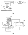
- FIG. 2 is a diagram of a device for measuring a current according to an embodiment of the present invention.
- the device includes a copper bar 210, a temperature sensor 220, a temperature sampling detector 230, a voltage sampling detector 240, an analog-digital converter 250, and a controller 260.
- Two sampling points that is, a first sampling point and a second sampling point, are selected on the copper bar 210.
- the two sampling points are secured by using a screw (or a buckle).
- the first sampling point and the second sampling point are connected to the voltage sampling detector 240.
- the temperature sensor 220 is placed between the two sampling points, and is also secured by using a screw (or a buckle).
- the temperature sensor 220 is connected to the temperature sampling detector 230.
- the temperature sampling detector 230 and the voltage sampling detector 240 are connected to the controller 260, where the analog-digital converter 250 may be integrated inside the controller 260; or the analog-digital converter is integrated outside the controller 260, that is, the analog-digital converter 250 is deployed separately. In this embodiment of the present invention, integrating the analog-digital converter 250 inside the controller 260 is taken as an example.
- the copper bar 210 in the device is configured to carry a current to be measured.
- the temperature sensor 220 is configured to measure a temperature between the first sampling point and the second sampling point located on the copper bar, and output a first signal according to the measured temperature.
- the temperature sensor 220 is placed between the two sampling points, and is secured by using a screw (or a buckle). The temperature sensor 220 measures the temperature at any point between the two sampling points. After the copper bar is fed with a direct current or an alternating current, the temperature sensor 220 starts to operate, and measures the temperature at any point between the first sampling point and the second sampling point.
- the temperature sensor 220 has various types. In practical applications, other types of temperature sensors can be used, for example, an integrated temperature sensor which has an analog-digital conversion integrated inside and provides digital bus communication externally; a current-type temperature sensor, where the signal output by the sensor is a current signal which is converted into a voltage signal after being sampled and detected; a voltage-type temperature sensor, where the signal output by the sensor is a voltage signal.
- any type of temperature sensor may operate normally when a direct current or an alternating current passes through it.
- a thermistor-type temperature sensor is taken as an example, and the temperature sensor outputs a voltage signal.
- the temperature sensor is a thermistor-type temperature sensor, and the temperature sensor outputs a voltage signal, where the voltage signal represents a temperature value at any point between the sampling points.
- the temperature sensor 220 is fed with an external power supply or an internal power supply.
- the temperature sampling detector 230 is configured to receive the first signal output by the temperature sensor, and output a second signal after sampling and filtering the first signal.
- the temperature sampling detector 230 samples, filters, and proportionally scales the first signal, and outputs a second signal after the processing.
- the voltage sampling detector 240 is configured to detect a first voltage signal at the first sampling point located on the copper bar and a second voltage signal at the second sampling point located on the copper bar, sample and filter a signal difference between the first voltage signal and the second voltage signal, and output a third voltage signal.
- the voltage sampling detection circuit 240 is connected to the first sampling point and the second sampling point on the copper bar, and detects the first voltage signal at the first sampling point and the second voltage signal at the second sampling point, obtains the signal difference between the first voltage signal and the second voltage signal, samples, filters, and proportionally scales the signal difference of the sampling points, and outputs a third voltage signal after the processing.
- selected temperature sensors 220 may be different in type, the first signals output by the temperature sensors 220 are different.
- a temperature sensor 220 outputs a voltage signal
- the first signal represents the temperature between the first sampling point and the second sampling point
- the first voltage signal and the second voltage signal represent voltages generated by the first sampling point and the second sampling point respectively when a current passes through.
- the analog-digital converter 250 is configured to: receive the second signal output by the temperature sampling detector, convert the second signal into a first digital signal, and output the first digital signal; and receive the third voltage signal output by the voltage sampling detector, convert the third voltage signal into a second digital signal, and output the second digital signal.
- the controller 260 is configured to: receive the first digital signal and the second digital signal output by the analog-digital converter, restore, according to the first digital signal, the second signal to a temperature value representing a temperature between the first sampling point and the second sampling point, and calculate a resistance value between the first sampling point and the second sampling point according to the temperature value; and restore, according to the second digital signal, the third voltage signal to a voltage value representing a voltage between the first sampling point and the second sampling point, and calculate, according to the voltage value and the resistance value, the value of a current between the first sampling point and the second sampling point.
- the controller 260 receives the first digital signal obtained after the processing performed by the analog-digital converter 250, restores the first digital signal to a temperature value representing a temperature between the first sampling point and the second sampling point. Then the controller 260 invokes a self-stored resistance-temperature comparison table or a resistance-temperature formula, and calculates the resistance value between the first sampling point and the second temperature value according to the temperature value.
- the controller 260 further receives the second digital signal obtained after the processing performed by the analog-digital converter 250, and restores the second digital signal to a voltage value representing a voltage between the first sampling point and the second sampling point.
- the controller 260 calculates the value of a current between the first sampling point and the second sampling point by using the voltage value and the resistance value.
- the analog-digital converter 250 is integrated outside the controller 260, that is, when the analog-digital converter 250 is deployed separately, the device may further include: a first analog-digital converter 310 and a second analog-digital converter 320.
- the first analog-digital converter 310 is connected to the temperature sampling detector 230, and is configured to receive the second signal, convert the second signal into a first digital signal, and transmit the first digital signal to the controller 260.
- the second analog-digital converter 320 is connected to the voltage sampling detector 240, and is configured to receive the third voltage signal, convert the third voltage signal into a second digital signal, and transmit the second digital signal to the controller 260.
- the analog-digital converter 250 is integrated inside the controller 260, meanwhile the first analog-digital converter 310 or second analog-digital converter 320 may be added to the device alternatively, so as to simplify the work load of the controller, improve the arithmetic speed of the controller, and enhance analog-digital conversion precision.
- the analog-digital converter 250 is integrated inside the controller 260, the first analog-digital converter 310 may be alternatively added.
- the first analog-digital converter 310 is connected to the temperature sampling detector 230, the first analog-digital converter 310 receives the second signal, converts the second signal into a first digital signal, and directly transmits the first digital signal to the controller 260.
- the controller 260 is further connected to the voltage sampling detector 240.
- the voltage sampling detector 240 directly transmits the third voltage signal to the controller 260; and the controller 260 converts the third voltage signal into a second digital signal by using the built-in integrated analog-digital converter 250, and converts the second digital signal into the voltage value between the sampling points.
- the analog-digital converter 250 is integrated inside the controller 260, and the second analog-digital converter 320 may be alternatively added.
- the second analog-digital converter 320 is connected to the voltage sampling detector 240; and the second analog-digital converter 320 receives the third voltage signal, converts the third voltage signal into a second digital signal, and directly transmits the second digital signal to the controller 260.
- the controller 260 is further connected to the temperature sampling detector 230.
- the temperature sampling detector 230 directly transmits the second signal to the controller 260.
- the controller 260 converts the second signal into a first digital signal by using the built-in integrated analog-digital converter 250, converts the first digital signal into the temperature value between the sampling points, and further calculates the resistance value between the sampling points.
- FIG. 4-C shows another form of a device for measuring a current.
- the temperature sampling detector 230 is replaced by a digital communication bus.
- the integrated temperature sensor converts the measured temperature into a digital signal, and communicates with an on-chip peripheral bus corresponding to the controller 260 by using a digital bus interface such as I2C, onewire, SPI, or the like.
- the controller 260 reads, through the on-chip peripheral bus, the digital signal sampled by the integrated temperature sensor, and converts the digital signal into the temperature value between the first sampling point and the second sampling point.
- the device further includes a power supply, which is not shown in the figure.
- the power supply loads a direct current or an alternating current for the copper bar 210.
- each component in the device for measuring a current is described by taking an example that the power supply loads a direct current. In practical applications, the power supply may also load an alternating current.
- an alternating current is loaded, functions of the components in the device for measuring a current are the same, which are not described herein again.
- the voltage sampling detector 240 and/or second analog-digital converter 320 should be isolated, to reduce the electrical interference of the two components on other components.
- multiple holes and/or apertures may be further arranged on the copper bar 210 in the embodiment of the present invention, to increase the resistance value of the copper bar 210, reduce the current passing through the copper bar 210, and indirectly reduce the power consumption.
- the sectional area of the copper bar 210 is decreased to reduce the heat emitted by the copper bar 210, as shown in FIG. 5-A, FIG. 5-B, and FIG. 5-C .
- the manner of decreasing the sectional area of the copper bar is not limited to the three types shown in FIG. 5-A, FIG. 5-B, and FIG. 5-C .
- the temperature sensor measures the temperature at any point between the sampling points on the copper bar; the controller converts the signal output by the temperature sensor into the temperature value and the resistance value of the sampling points on the copper bar, and indirectly measures the value of the current passing through the sampling points by using the resistance value and the voltage value of the sampling points.
- multiple holes or apertures are arranged on the copper bar, which indirectly increases the resistance of the copper bar and reduces current power consumption, so as to lower the temperature of the copper bar, thereby improving the stability of a measuring system.
- FIG. 6 is a flowchart of a method for measuring a current according to an embodiment of the present invention.
- the method shown in FIG. 6 is implemented based on the aforementioned device embodiment. Based on the device for measuring a current, the method for measuring a current specifically includes the following steps:
- Step 610 Measure a temperature between a first sampling point and a second sampling point on a copper bar carrying a current to be measured, and output a first signal according to the measured temperature.
- two sampling points that is, a first sampling point and a second sampling point
- the two sampling points are secured by using a screw (or a buckle).
- a direct current or an alternating current is provided, the temperature at any point between the two sampling points is measured.
- the first signal is output according to the measured temperature.
- the current to be measured is carried on the copper bar.
- Step 620 Output a second signal after the first signal is sampled and filtered.
- the first signal is sampled, filtered, and proportionally scaled, and a second signal is output after the processing.
- Step 630 Detect a first voltage signal at the first sampling point and a second voltage signal at the second sampling point, sample and filter a signal difference between the first voltage signal and the second voltage signal, and output a third voltage signal.
- the copper bar is fed with a direct current or an alternating current, voltages appears at the first sampling point and the second sampling point on the copper bar.
- the first voltage signal at the first sampling point and the second voltage signal at the second sampling point are detected, the signal difference between the first voltage signal and the second voltage signal is obtained, the signal difference is sampled, filtered, and proportionally scaled, and a third voltage signal is output after the processing.
- Step 640 Convert the second signal into a first digital signal, restore, according to the first digital signal, the second signal to a temperature value representing a temperature between the first sampling point and the second sampling point, and calculate a resistance value between the first sampling point and the second sampling point according to the temperature value.
- the second signal is converted into the first digital signal
- the first digital signal is converted into the value representing a temperature between the first sampling point and the second sampling point
- a resistance-temperature comparison table or a resistance-temperature formula is invoked, and the resistance value between the first sampling point and the second sampling point at the temperature value is calculated.
- Step 650 Convert the third voltage signal into a second digital signal, and restore, according to the second digital signal, the third voltage signal to a voltage value representing a voltage between the first sampling point and the second sampling point.
- the third voltage signal is converted into a second digital signal
- the second digital signal is converted into the voltage value representing the voltage between the first sampling point and the second sampling point.
- Step 660 Calculate, according to the voltage value and the resistance value, the value of a current between the first sampling point and the second sampling point.
- the value of the current between the first sampling point and the second sampling point is calculated according to the resistance value obtained in step 640 and the voltage value obtained in step 650 by using the Ohm's law.
- multiple holes and/or apertures may be further arranged on the copper bar in the embodiments of the present invention, to increase the resistance value of the copper bar, reduce the current passing through the copper bar, and indirectly reduce the power consumption.
- the sectional area of the copper bar is decreased to reduce the heat emitted by the copper bar, as shown in FIG. 5-A, FIG. 5-B, and FIG. 5-C .
- the manner of decreasing the sectional area of the copper bar is not limited to the three types shown in FIG. 5-A, FIG. 5-B, and FIG. 5-C .
- the temperature at any point between the sampling points on the copper bar is measured; the signal representing the temperature is converted into the temperature value and the resistance value of the sampling points on the copper bar; and the value of the current passing through the sampling points is calculated indirectly by using the resistance value and the voltage value of the sampling points.
- multiple holes or apertures are arranged on the copper bar, which indirectly increases the resistance of the copper bar, so as to lower the temperature of the copper bar, thereby improving the stability of a measuring system.
Landscapes
- Physics & Mathematics (AREA)
- General Physics & Mathematics (AREA)
- Measurement Of Current Or Voltage (AREA)
Abstract
Description
- The present invention relates to the field of electronic technologies, and in particular, to a method and a device for measuring a current.
- A communication power supply is usually called the heart of a communication system. If the communication power supply works abnormally, a communication system fault may occur, and the whole system may even fail. Currently, a current diverter is used mostly to detect the current of a communication power supply.
- When being used to perform sampling detection on the current, the current diverter is equivalent to a resistor with a small temperature drift coefficient. Therefore, it is obtained from the Ohm's law that, the voltage is proportional to the current, and the value of the current passing through the current diverter is calculated proportionally by obtaining the voltage values at both ends of the current diverter.
- However, using the current diverter to perform sampling detection on the current has some inevitable defects. Because the current diverter has a large resistance value, when the current passing through the current diverter is 1000 A, a corresponding voltage drop of 75 MV is generated at the current diverter, and at this time, the power consumption of the current diverter is 75 W. Therefore, the power consumption of the current diverter is large. Because the large power consumption causes the temperature value of the current diverter to rise, and the resistance of the current diverter may change with the temperature, the stability of the current diverter is reduced. In addition, the cost of manufacturing the current diverter is relatively high.
- Embodiments of the present invention disclose a method and a device for measuring a current, so as to reduce power consumption during the process of current sampling detection, and improve the stability of the current detection.
- In a first aspect, an embodiment of the present invention provides a method for measuring a current, including: measuring a temperature between a first sampling point and a second sampling point on a copper bar carrying a current to be measured, and outputting a first signal according to the measured temperature;
outputting a second signal after sampling and filtering the first signal;
detecting a first voltage signal at the first sampling point and a second voltage signal at the second sampling point, sampling and filtering a signal difference between the first voltage signal and the second voltage signal, and outputting a third voltage signal;
converting the second signal into a first digital signal, restoring, according to the first digital signal, the second signal to a temperature value representing a temperature between the first sampling point and the second sampling point, and calculating a resistance value between the first sampling point and the second sampling point according to the temperature value;
converting the third voltage signal into a second digital signal, and restoring, according to the second digital signal, the third voltage signal to a voltage value representing a voltage between the first sampling point and the second sampling point; and
calculating, according to the voltage value and the resistance value, a value of a current between the first sampling point and the second sampling point. - In a first possible implementation manner, the calculating a resistance value between the first sampling point and the second sampling point according to the temperature value specifically includes:
- calculating a resistance value corresponding to the temperature value by using a resistance-temperature comparison table or a resistance-temperature formula.
- With reference to the first aspect or the first possible implementation manner of the first aspect, in a second possible implementation manner, the copper bar between the first sampling point and the second sampling point has multiple holes and/or multiple apertures, so as to decrease the area of the copper bar to increase the resistance value of the copper bar.
- In a second aspect, an embodiment of the present invention provides a device for measuring a current, where the device includes:
- a copper bar, configured to carry a current to be measured;
- a temperature sensor, configured to measure a temperature between a first sampling point and a second sampling point located on the copper bar, and output a first signal according to the measured temperature;
- a temperature sampling detector, configured to receive the first signal output by the temperature sensor, and output a second signal after sampling and filtering the first signal;
- a voltage sampling detector, configured to detect a first voltage signal at the first sampling point located on the copper bar and a second voltage signal at the second sampling point located on the copper bar, sample and filter a signal difference between the first voltage signal and the second voltage signal, and output a third voltage signal;
- an analog-digital converter, configured to: receive the second signal output by the temperature sampling detector, convert the second signal into a first digital signal, and output the first digital signal; and receive the third voltage signal output by the voltage sampling detector, convert the third voltage signal into a second digital signal, and output the second digital signal; and
- a controller, configured to: receive the first digital signal and the second digital signal output by the analog-digital converter, restore, according to the first digital signal, the second signal to a temperature value representing a temperature between the first sampling point and the second sampling point, and calculate a resistance value between the first sampling point and the second sampling point according to the temperature value; and restore, according to the second digital signal, the third voltage signal to a voltage value representing a voltage between the first sampling point and the second sampling point, and calculate, according to the voltage value and the resistance value, the value of a current between the first sampling point and the second sampling point.
- In a first possible implementation manner, the controller is specifically configured to: calculate the resistance value between the first sampling point and the second sampling point and corresponding to the temperature value, by using a resistance-temperature comparison table or a resistance-temperature formula.
- With reference to the second aspect or the first possible implementation manner of the second aspect, in a second possible implementation manner, the analog-digital converter is integrated inside the controller; or the analog-digital converter is integrated outside the controller.
- With reference to the second aspect or the first or the second possible implementation manner of the second aspect, in a third possible implementation manner, the copper bar has multiple holes and/or multiple apertures, so as to decrease the area of the copper bar to increase the resistance value of the copper bar.
- With the method and device for measuring a current provided by the embodiments of the present invention, the temperature sensor measures the temperature at any point between the sampling points on the copper bar, the controller converts the signal output by the temperature sensor into the temperature value and the resistance value of the sampling points on the copper bar, and indirectly measures the value of a current passing through the sampling points by using the resistance value and the voltage value of the sampling points. Meanwhile, multiple holes or apertures are arranged on the copper bar, which indirectly increases the resistance of the copper bar and reduces current power consumption, so as to lower the temperature of the copper bar, thereby improving the stability of a measuring system.
-
-
FIG. 1 is a structural diagram of measuring a current according to an embodiment of the present invention; -
FIG. 2 is a diagram of a device for measuring a current according to an embodiment of the present invention; -
FIG. 3 is a schematic diagram of integrating analog-digital converters externally according to an embodiment of the present invention; -
FIG. 4-A is a schematic diagram of integrating a first analog-digital converter externally according to an embodiment of the present invention; -
FIG. 4-B is a schematic diagram of integrating a second analog-digital converter externally according to an embodiment of the present invention; -
FIG. 4-C is a schematic diagram of measuring a current by using an integrated temperature sensor according to an embodiment of the present invention; -
FIG. 5-A is a schematic diagram of arranging copper bar holes and/or apertures according to an embodiment of the present invention; -
FIG. 5-B is a schematic diagram of arranging copper bar holes and/or apertures according to another embodiment of the present invention; -
FIG. 5-C is a schematic diagram of arranging copper bar holes and/or apertures according to still another embodiment of the present invention; and -
FIG. 6 is a flowchart of a method for measuring a current according to an embodiment of the present invention. - To make the objectives, technical solutions, and advantages of the embodiments of the present invention more clearly, the following further describes the embodiments of the present invention with reference to the accompanying drawings.
- The following takes
FIG. 1 as an example to describe in detail the device for measuring a current provided in an embodiment of the present invention.FIG. 1 is a structural diagram of measuring a current according to an embodiment of the present invention. - As shown in
FIG. 1 , a temperature and a voltage between a first sampling point and a second sampling point are measured; the measured temperature between the first sampling point and the second sampling point undergoes sampling detection and analog-digital conversion, and then is converted into a resistance value between the first sampling point and the second sampling point; the measured voltage between the first sampling point and the second sampling point undergoes sampling detection and analog-digital conversion, and then is converted into a voltage value between the first sampling point and the second sampling point; and the value of a current between the first sampling point and the second sampling point on a copper bar is calculated by using the resistance value and the voltage value between the first sampling point and the second sampling point. - The following takes
FIG. 2 as an example to describe in detail the device for measuring a current provided in an embodiment of the present invention.FIG. 2 is a diagram of a device for measuring a current according to an embodiment of the present invention. - As shown in
FIG. 2 , the device includes acopper bar 210, atemperature sensor 220, atemperature sampling detector 230, avoltage sampling detector 240, an analog-digital converter 250, and acontroller 260. - Two sampling points, that is, a first sampling point and a second sampling point, are selected on the
copper bar 210. The two sampling points are secured by using a screw (or a buckle). The first sampling point and the second sampling point are connected to thevoltage sampling detector 240. Thetemperature sensor 220 is placed between the two sampling points, and is also secured by using a screw (or a buckle). Thetemperature sensor 220 is connected to thetemperature sampling detector 230. Thetemperature sampling detector 230 and thevoltage sampling detector 240 are connected to thecontroller 260, where the analog-digital converter 250 may be integrated inside thecontroller 260; or the analog-digital converter is integrated outside thecontroller 260, that is, the analog-digital converter 250 is deployed separately. In this embodiment of the present invention, integrating the analog-digital converter 250 inside thecontroller 260 is taken as an example. - The
copper bar 210 in the device is configured to carry a current to be measured. - The
temperature sensor 220 is configured to measure a temperature between the first sampling point and the second sampling point located on the copper bar, and output a first signal according to the measured temperature. - Specifically, the
temperature sensor 220 is placed between the two sampling points, and is secured by using a screw (or a buckle). Thetemperature sensor 220 measures the temperature at any point between the two sampling points. After the copper bar is fed with a direct current or an alternating current, thetemperature sensor 220 starts to operate, and measures the temperature at any point between the first sampling point and the second sampling point. - It should be understood that, the
temperature sensor 220 has various types. In practical applications, other types of temperature sensors can be used, for example, an integrated temperature sensor which has an analog-digital conversion integrated inside and provides digital bus communication externally; a current-type temperature sensor, where the signal output by the sensor is a current signal which is converted into a voltage signal after being sampled and detected; a voltage-type temperature sensor, where the signal output by the sensor is a voltage signal. In addition, any type of temperature sensor may operate normally when a direct current or an alternating current passes through it. In the embodiment of the present invention, a thermistor-type temperature sensor is taken as an example, and the temperature sensor outputs a voltage signal. The temperature sensor is a thermistor-type temperature sensor, and the temperature sensor outputs a voltage signal, where the voltage signal represents a temperature value at any point between the sampling points. - It should be noted that, the
temperature sensor 220 is fed with an external power supply or an internal power supply. - The
temperature sampling detector 230 is configured to receive the first signal output by the temperature sensor, and output a second signal after sampling and filtering the first signal. - Specifically, the
temperature sampling detector 230 samples, filters, and proportionally scales the first signal, and outputs a second signal after the processing. - The
voltage sampling detector 240 is configured to detect a first voltage signal at the first sampling point located on the copper bar and a second voltage signal at the second sampling point located on the copper bar, sample and filter a signal difference between the first voltage signal and the second voltage signal, and output a third voltage signal. - Specifically, the voltage
sampling detection circuit 240 is connected to the first sampling point and the second sampling point on the copper bar, and detects the first voltage signal at the first sampling point and the second voltage signal at the second sampling point, obtains the signal difference between the first voltage signal and the second voltage signal, samples, filters, and proportionally scales the signal difference of the sampling points, and outputs a third voltage signal after the processing. - It should be understood that, because selected
temperature sensors 220 may be different in type, the first signals output by thetemperature sensors 220 are different. When atemperature sensor 220 outputs a voltage signal, the content to be measured for the first signal or the first voltage signal or the second voltage signal is different. The first signal represents the temperature between the first sampling point and the second sampling point, and the first voltage signal and the second voltage signal represent voltages generated by the first sampling point and the second sampling point respectively when a current passes through. - The analog-
digital converter 250 is configured to: receive the second signal output by the temperature sampling detector, convert the second signal into a first digital signal, and output the first digital signal; and receive the third voltage signal output by the voltage sampling detector, convert the third voltage signal into a second digital signal, and output the second digital signal. - The
controller 260 is configured to: receive the first digital signal and the second digital signal output by the analog-digital converter, restore, according to the first digital signal, the second signal to a temperature value representing a temperature between the first sampling point and the second sampling point, and calculate a resistance value between the first sampling point and the second sampling point according to the temperature value; and restore, according to the second digital signal, the third voltage signal to a voltage value representing a voltage between the first sampling point and the second sampling point, and calculate, according to the voltage value and the resistance value, the value of a current between the first sampling point and the second sampling point. - Specifically, the
controller 260 receives the first digital signal obtained after the processing performed by the analog-digital converter 250, restores the first digital signal to a temperature value representing a temperature between the first sampling point and the second sampling point. Then thecontroller 260 invokes a self-stored resistance-temperature comparison table or a resistance-temperature formula, and calculates the resistance value between the first sampling point and the second temperature value according to the temperature value. - The
controller 260 further receives the second digital signal obtained after the processing performed by the analog-digital converter 250, and restores the second digital signal to a voltage value representing a voltage between the first sampling point and the second sampling point. - The
controller 260 calculates the value of a current between the first sampling point and the second sampling point by using the voltage value and the resistance value. - In a preferred embodiment, as shown in
FIG. 3 , the analog-digital converter 250 is integrated outside thecontroller 260, that is, when the analog-digital converter 250 is deployed separately, the device may further include: a first analog-digital converter 310 and a second analog-digital converter 320. The first analog-digital converter 310 is connected to thetemperature sampling detector 230, and is configured to receive the second signal, convert the second signal into a first digital signal, and transmit the first digital signal to thecontroller 260. - The second analog-
digital converter 320 is connected to thevoltage sampling detector 240, and is configured to receive the third voltage signal, convert the third voltage signal into a second digital signal, and transmit the second digital signal to thecontroller 260. - Further, in another preferred embodiment, if the analog-
digital converter 250 is integrated inside thecontroller 260, meanwhile the first analog-digital converter 310 or second analog-digital converter 320 may be added to the device alternatively, so as to simplify the work load of the controller, improve the arithmetic speed of the controller, and enhance analog-digital conversion precision. As shown inFIG. 4-A andFIG. 4-B , and as shownFIG. 4-A , the analog-digital converter 250 is integrated inside thecontroller 260, the first analog-digital converter 310 may be alternatively added. The first analog-digital converter 310 is connected to thetemperature sampling detector 230, the first analog-digital converter 310 receives the second signal, converts the second signal into a first digital signal, and directly transmits the first digital signal to thecontroller 260. Thecontroller 260 is further connected to thevoltage sampling detector 240. Thevoltage sampling detector 240 directly transmits the third voltage signal to thecontroller 260; and thecontroller 260 converts the third voltage signal into a second digital signal by using the built-in integrated analog-digital converter 250, and converts the second digital signal into the voltage value between the sampling points. - As shown in
FIG. 4-B , the analog-digital converter 250 is integrated inside thecontroller 260, and the second analog-digital converter 320 may be alternatively added. The second analog-digital converter 320 is connected to thevoltage sampling detector 240; and the second analog-digital converter 320 receives the third voltage signal, converts the third voltage signal into a second digital signal, and directly transmits the second digital signal to thecontroller 260. Thecontroller 260 is further connected to thetemperature sampling detector 230. Thetemperature sampling detector 230 directly transmits the second signal to thecontroller 260. Thecontroller 260 converts the second signal into a first digital signal by using the built-in integrated analog-digital converter 250, converts the first digital signal into the temperature value between the sampling points, and further calculates the resistance value between the sampling points. - It should be noted that, in the above embodiments, none of the
temperature sensors 220 is an integrated temperature sensor. However, in practical applications, integrated temperature sensors may also be used. As shown inFIG. 4-C, FIG. 4-C shows another form of a device for measuring a current. When thetemperature sensor 220 is an integrated temperature sensor, thetemperature sampling detector 230 is replaced by a digital communication bus. - The integrated temperature sensor converts the measured temperature into a digital signal, and communicates with an on-chip peripheral bus corresponding to the
controller 260 by using a digital bus interface such as I2C, onewire, SPI, or the like. Thecontroller 260 reads, through the on-chip peripheral bus, the digital signal sampled by the integrated temperature sensor, and converts the digital signal into the temperature value between the first sampling point and the second sampling point. - It should be further noted that, the device further includes a power supply, which is not shown in the figure. The power supply loads a direct current or an alternating current for the
copper bar 210. In the above embodiments, each component in the device for measuring a current is described by taking an example that the power supply loads a direct current. In practical applications, the power supply may also load an alternating current. When an alternating current is loaded, functions of the components in the device for measuring a current are the same, which are not described herein again. However, when the alternating current is loaded, in order to reduce the electrical interference of an alternating voltage on other components, thevoltage sampling detector 240 and/or second analog-digital converter 320 should be isolated, to reduce the electrical interference of the two components on other components. - It should be further noted that, in order to reduce power consumption, and solve the problem of heat emission from the
copper bar 210, multiple holes and/or apertures may be further arranged on thecopper bar 210 in the embodiment of the present invention, to increase the resistance value of thecopper bar 210, reduce the current passing through thecopper bar 210, and indirectly reduce the power consumption. In addition, on the basis of retaining the heat dissipation area of thecopper bar 210 between the sampling points, the sectional area of thecopper bar 210 is decreased to reduce the heat emitted by thecopper bar 210, as shown inFIG. 5-A, FIG. 5-B, and FIG. 5-C . However, the manner of decreasing the sectional area of the copper bar is not limited to the three types shown inFIG. 5-A, FIG. 5-B, and FIG. 5-C . - With the device for measuring a current provided by the embodiment of the present invention, the temperature sensor measures the temperature at any point between the sampling points on the copper bar; the controller converts the signal output by the temperature sensor into the temperature value and the resistance value of the sampling points on the copper bar, and indirectly measures the value of the current passing through the sampling points by using the resistance value and the voltage value of the sampling points. Meanwhile, multiple holes or apertures are arranged on the copper bar, which indirectly increases the resistance of the copper bar and reduces current power consumption, so as to lower the temperature of the copper bar, thereby improving the stability of a measuring system.
- The following takes
FIG. 6 as an example to describe in detail a method for measuring a current provided in an embodiment of the present invention.FIG. 6 is a flowchart of a method for measuring a current according to an embodiment of the present invention. - The method shown in
FIG. 6 is implemented based on the aforementioned device embodiment. Based on the device for measuring a current, the method for measuring a current specifically includes the following steps: - Step 610: Measure a temperature between a first sampling point and a second sampling point on a copper bar carrying a current to be measured, and output a first signal according to the measured temperature.
- Specifically, two sampling points, that is, a first sampling point and a second sampling point, are selected on the copper bar. The two sampling points are secured by using a screw (or a buckle). After a direct current or an alternating current is provided, the temperature at any point between the two sampling points is measured. In this embodiment of the present invention, the first signal is output according to the measured temperature. In this embodiment of the present invention, after the copper bar is fed with a direct current or an alternating current, the current to be measured is carried on the copper bar.
- Step 620: Output a second signal after the first signal is sampled and filtered.
- Specifically, based on the description in
step 610, the first signal is sampled, filtered, and proportionally scaled, and a second signal is output after the processing. - Step 630: Detect a first voltage signal at the first sampling point and a second voltage signal at the second sampling point, sample and filter a signal difference between the first voltage signal and the second voltage signal, and output a third voltage signal.
- Specifically, because the copper bar is fed with a direct current or an alternating current, voltages appears at the first sampling point and the second sampling point on the copper bar. The first voltage signal at the first sampling point and the second voltage signal at the second sampling point are detected, the signal difference between the first voltage signal and the second voltage signal is obtained, the signal difference is sampled, filtered, and proportionally scaled, and a third voltage signal is output after the processing.
- Step 640: Convert the second signal into a first digital signal, restore, according to the first digital signal, the second signal to a temperature value representing a temperature between the first sampling point and the second sampling point, and calculate a resistance value between the first sampling point and the second sampling point according to the temperature value.
- Specifically, based on the description in the above steps, the second signal is converted into the first digital signal, and the first digital signal is converted into the value representing a temperature between the first sampling point and the second sampling point, a resistance-temperature comparison table or a resistance-temperature formula is invoked, and the resistance value between the first sampling point and the second sampling point at the temperature value is calculated.
- Step 650: Convert the third voltage signal into a second digital signal, and restore, according to the second digital signal, the third voltage signal to a voltage value representing a voltage between the first sampling point and the second sampling point.
- Specifically, based on the description in the above steps, the third voltage signal is converted into a second digital signal, and the second digital signal is converted into the voltage value representing the voltage between the first sampling point and the second sampling point.
- Step 660: Calculate, according to the voltage value and the resistance value, the value of a current between the first sampling point and the second sampling point.
- Specifically, the value of the current between the first sampling point and the second sampling point is calculated according to the resistance value obtained in
step 640 and the voltage value obtained instep 650 by using the Ohm's law. - It should be further noted that, in order to reduce power consumption, and solve the problem of heat emission from the copper bar, multiple holes and/or apertures may be further arranged on the copper bar in the embodiments of the present invention, to increase the resistance value of the copper bar, reduce the current passing through the copper bar, and indirectly reduce the power consumption. In addition, on the basis of retaining the heat dissipation area of the copper bar between the sampling points, the sectional area of the copper bar is decreased to reduce the heat emitted by the copper bar, as shown in
FIG. 5-A, FIG. 5-B, and FIG. 5-C . However, the manner of decreasing the sectional area of the copper bar is not limited to the three types shown inFIG. 5-A, FIG. 5-B, and FIG. 5-C . - With the method for measuring a current provided by the embodiment of the present invention, the temperature at any point between the sampling points on the copper bar is measured; the signal representing the temperature is converted into the temperature value and the resistance value of the sampling points on the copper bar; and the value of the current passing through the sampling points is calculated indirectly by using the resistance value and the voltage value of the sampling points. Meanwhile, multiple holes or apertures are arranged on the copper bar, which indirectly increases the resistance of the copper bar, so as to lower the temperature of the copper bar, thereby improving the stability of a measuring system.
- Those skilled in the art may further realize that, the components and steps described in the embodiments of the present invention may be implemented by using electronic hardware, computer software, or a combination thereof; and in order to clearly describe the interchangeability between hardware and software, the above specification describes combinations and steps of various embodiments generally according to functions. Whether the functions are performed by hardware or software depends on particular applications and design constraint conditions of the technical solutions. Those skilled in the art may use different methods for each specific application to implement the described functions; however, this implementation shall not be deemed as going beyond the scope of the present invention.
- The objectives, technical solutions, and benefits of the present invention are further described in detail in the foregoing specific embodiments. It should be understood that the foregoing description is merely about the specific embodiments of the present invention, but is not intended to limit the protection scope of the present invention. Any modification, equivalent replacement, or improvement made within the idea and principle of the present invention shall fall within the protection scope of the present invention.
Claims (7)
- A method for measuring a current, comprising:measuring a temperature between a first sampling point and a second sampling point on a copper bar carrying a current to be measured, and outputting a first signal according to the measured temperature;outputting a second signal after sampling and filtering the first signal;detecting a first voltage signal at the first sampling point and a second voltage signal at the second sampling point, sampling and filtering a signal difference between the first voltage signal and the second voltage signal, and outputting a third voltage signal;converting the second signal into a first digital signal, restoring, according to the first digital signal, the second signal to a temperature value representing the temperature between the first sampling point and the second sampling point, and calculating a resistance value between the first sampling point and the second sampling point according to the temperature value;converting the third voltage signal into a second digital signal, and restoring, according to the second digital signal, the third voltage signal to a voltage value representing a voltage between the first sampling point and the second sampling point; andcalculating, according to the voltage value and the resistance value, a value of a current between the first sampling point and the second sampling point.
- The method for measuring a current according to claim 1, wherein the calculating a resistance value between the first sampling point and the second sampling point according to the temperature value specifically comprises:calculating a resistance value corresponding to the temperature value by using a resistance-temperature comparison table or a resistance-temperature formula.
- The method for measuring a current according to claim 1 or 2, wherein the copper bar between the first sampling point and the second sampling point has multiple holes and/or multiple apertures, so as to decrease an area of the copper bar to increase a resistance value of the copper bar.
- A device for measuring a current, comprising:a copper bar, configured to carry a current to be measured;a temperature sensor, configured to measure a temperature between a first sampling point and a second sampling point located on the copper bar, and output a first signal according to the measured temperature;a temperature sampling detector, configured to receive the first signal output by the temperature sensor, and output a second signal after sampling and filtering the first signal;a voltage sampling detector, configured to detect a first voltage signal at the first sampling point located on the copper bar and a second voltage signal at the second sampling point located on the copper bar, sample and filter a signal difference between the first voltage signal and the second voltage signal, and output a third voltage signal;an analog-digital converter, configured to: receive the second signal output by the temperature sampling detector, convert the second signal into a first digital signal, and output the first digital signal; and receive the third voltage signal output by the voltage sampling detector, convert the third voltage signal into a second digital signal, and output the second digital signal; anda controller, configured to: receive the first digital signal and the second digital signal output by the analog-digital converter, restore, according to the first digital signal, the second signal to a temperature value representing the temperature between the first sampling point and the second sampling point, and calculate a resistance value between the first sampling point and the second sampling point according to the temperature value; and restore the third voltage signal to a voltage value representing a voltage between the first sampling point and the second sampling point according to the second digital signal, and calculate, according to the voltage value and the resistance value, a value of a current between the first sampling point and the second sampling point.
- The device for measuring a current according to claim 4, wherein the controller is specifically configured to:calculate the resistance value between the first sampling point and the second sampling point and corresponding to the temperature value by using a resistance-temperature comparison table or a resistance-temperature formula.
- The device for measuring a current according to claim 4 or 5, wherein the analog-digital converter is integrated inside the controller; or the analog-digital converter is integrated outside the controller.
- The device for measuring a current according to any one of claims 4 to 6, wherein the copper bar has multiple holes and/or multiple apertures, so as to decrease an area of the copper bar to increase a resistance value of the copper bar.
Applications Claiming Priority (2)
| Application Number | Priority Date | Filing Date | Title |
|---|---|---|---|
| CN201210426192.3A CN102928657B (en) | 2012-10-31 | 2012-10-31 | Current measurement method and device |
| PCT/CN2013/073877 WO2014067259A1 (en) | 2012-10-31 | 2013-04-08 | Method and device for measuring current |
Publications (2)
| Publication Number | Publication Date |
|---|---|
| EP2752673A1 true EP2752673A1 (en) | 2014-07-09 |
| EP2752673A4 EP2752673A4 (en) | 2014-07-30 |
Family
ID=47643503
Family Applications (1)
| Application Number | Title | Priority Date | Filing Date |
|---|---|---|---|
| EP20130798536 Withdrawn EP2752673A4 (en) | 2012-10-31 | 2013-04-08 | Method and device for measuring current |
Country Status (3)
| Country | Link |
|---|---|
| EP (1) | EP2752673A4 (en) |
| CN (1) | CN102928657B (en) |
| WO (1) | WO2014067259A1 (en) |
Families Citing this family (9)
| Publication number | Priority date | Publication date | Assignee | Title |
|---|---|---|---|---|
| CN102928657B (en) * | 2012-10-31 | 2015-07-22 | 华为技术有限公司 | Current measurement method and device |
| US9482696B2 (en) | 2012-10-31 | 2016-11-01 | Huawei Technologies Co., Ltd. | Method and device for measuring current |
| CN104849665B (en) * | 2014-02-19 | 2018-01-30 | 中国移动通信集团河北有限公司 | A kind of method and device for determining storage battery safety electric discharge duration |
| CN104215821B (en) * | 2014-09-18 | 2017-02-01 | 青岛歌尔声学科技有限公司 | Method for detecting input surge current of power device |
| US9823154B2 (en) * | 2014-11-12 | 2017-11-21 | Kidde Technologies, Inc. | Bleed air duct leak system real-time fault detection |
| CN108809193A (en) * | 2018-05-24 | 2018-11-13 | 北京交通大学 | A kind of induction machine resistance discrimination method suitable for subway current transformer |
| CN111965554B (en) * | 2020-07-31 | 2023-05-30 | 蜂巢能源科技股份有限公司 | Method and device for detecting copper bar connection in battery pack, storage medium and electronic equipment |
| CN112874378B (en) * | 2021-01-27 | 2022-12-09 | 一汽解放汽车有限公司 | Method, device and equipment for processing battery sampling temperature and vehicle |
| CN117554677B (en) * | 2024-01-11 | 2024-04-23 | 武汉嘉晨电子技术有限公司 | Current sensor |
Citations (2)
| Publication number | Priority date | Publication date | Assignee | Title |
|---|---|---|---|---|
| DE102004042719A1 (en) * | 2004-09-03 | 2005-09-29 | Audi Ag | Current sensor has measurement resistance made as narrower length or meander integrated in same material as conductor |
| US20090087725A1 (en) * | 2007-09-28 | 2009-04-02 | Samsung Sdi Co., Ltd. | Temperature compensated current measuring device and battery pack using the same |
Family Cites Families (4)
| Publication number | Priority date | Publication date | Assignee | Title |
|---|---|---|---|---|
| FR2802302B1 (en) * | 1999-12-09 | 2002-02-15 | Sagem | APPARATUS FOR MEASURING THE CURRENT INTENSITY IN A CONDUCTOR |
| US7173429B2 (en) * | 2003-12-12 | 2007-02-06 | Power Designers, Llc | Activity-based battery monitor with a universal current measuring apparatus |
| CN101650408B (en) * | 2008-08-12 | 2011-11-30 | 华为技术有限公司 | Method, device and equipment for detecting on-line power consumption of load of integrated circuit |
| CN102928657B (en) * | 2012-10-31 | 2015-07-22 | 华为技术有限公司 | Current measurement method and device |
-
2012
- 2012-10-31 CN CN201210426192.3A patent/CN102928657B/en active Active
-
2013
- 2013-04-08 EP EP20130798536 patent/EP2752673A4/en not_active Withdrawn
- 2013-04-08 WO PCT/CN2013/073877 patent/WO2014067259A1/en active Application Filing
Patent Citations (2)
| Publication number | Priority date | Publication date | Assignee | Title |
|---|---|---|---|---|
| DE102004042719A1 (en) * | 2004-09-03 | 2005-09-29 | Audi Ag | Current sensor has measurement resistance made as narrower length or meander integrated in same material as conductor |
| US20090087725A1 (en) * | 2007-09-28 | 2009-04-02 | Samsung Sdi Co., Ltd. | Temperature compensated current measuring device and battery pack using the same |
Non-Patent Citations (1)
| Title |
|---|
| See also references of WO2014067259A1 * |
Also Published As
| Publication number | Publication date |
|---|---|
| EP2752673A4 (en) | 2014-07-30 |
| CN102928657A (en) | 2013-02-13 |
| WO2014067259A1 (en) | 2014-05-08 |
| CN102928657B (en) | 2015-07-22 |
Similar Documents
| Publication | Publication Date | Title |
|---|---|---|
| EP2752673A1 (en) | Method and device for measuring current | |
| EP2413148B1 (en) | Insulation resistance measuring circuit free from influence of battery voltage | |
| JP6204474B2 (en) | Input power and current measurement system and method | |
| US10505370B2 (en) | Safety detection device and method of grid-connected inverter | |
| US20160054370A1 (en) | Ground fault detection based on capacitive sensing | |
| CN108501757B (en) | Battery management system, current sampling method and device and electric automobile | |
| WO2018107987A1 (en) | Current detection device, current detection system and current detection method | |
| KR20100105957A (en) | Insulation resistance measurement circuit using operational amplifier | |
| CN105651412A (en) | Measurement method and measurement circuit for PT1000 temperature sensor | |
| CN112730963A (en) | Automobile-level Hall current sensor with temperature compensation and compensation method thereof | |
| CN206515387U (en) | Current sensing means and current detecting system | |
| CN111880104B (en) | Detection circuit and method, detector, battery device, vehicle and computer-readable storage medium | |
| KR101925629B1 (en) | Apparatus Sensing Battery Using Hall sensor Intelligently | |
| KR102478075B1 (en) | Apparatus for reducing temperature effects in stray inductance based switching current measurement | |
| US9482696B2 (en) | Method and device for measuring current | |
| EP2767839B1 (en) | Root mean square detector and circuit breaker using the same | |
| JP6029340B2 (en) | DC switchboard system | |
| AU2014204547A1 (en) | Identifying defective electrical cables | |
| US20170288439A1 (en) | Signal processing circuit, coulomb counter circuit, and electronic device | |
| CN211718374U (en) | Current detection circuit and current detection equipment | |
| CN102288318A (en) | Temperature detection circuit of permanent magnet synchronous motor and controller system for electric vehicle | |
| CN109141495A (en) | Sensor interface apparatus | |
| WO2015047578A1 (en) | Infrared sensor | |
| CN209894872U (en) | Alternating current voltage sampling circuit structure and alternating current voltage detection device | |
| JP2012049955A (en) | Current/voltage conversion circuit and current detector |
Legal Events
| Date | Code | Title | Description |
|---|---|---|---|
| PUAI | Public reference made under article 153(3) epc to a published international application that has entered the european phase |
Free format text: ORIGINAL CODE: 0009012 |
|
| 17P | Request for examination filed |
Effective date: 20131209 |
|
| AK | Designated contracting states |
Kind code of ref document: A1 Designated state(s): AL AT BE BG CH CY CZ DE DK EE ES FI FR GB GR HR HU IE IS IT LI LT LU LV MC MK MT NL NO PL PT RO RS SE SI SK SM TR |
|
| A4 | Supplementary search report drawn up and despatched |
Effective date: 20140630 |
|
| RIC1 | Information provided on ipc code assigned before grant |
Ipc: G01R 31/36 20060101ALI20140624BHEP Ipc: G01R 19/25 20060101AFI20140624BHEP |
|
| 17Q | First examination report despatched |
Effective date: 20150513 |
|
| STAA | Information on the status of an ep patent application or granted ep patent |
Free format text: STATUS: THE APPLICATION IS DEEMED TO BE WITHDRAWN |
|
| DAX | Request for extension of the european patent (deleted) | ||
| 18D | Application deemed to be withdrawn |
Effective date: 20150924 |