EP2752569A1 - Throttle valve for internal combustion engines - Google Patents
Throttle valve for internal combustion engines Download PDFInfo
- Publication number
- EP2752569A1 EP2752569A1 EP13150306.2A EP13150306A EP2752569A1 EP 2752569 A1 EP2752569 A1 EP 2752569A1 EP 13150306 A EP13150306 A EP 13150306A EP 2752569 A1 EP2752569 A1 EP 2752569A1
- Authority
- EP
- European Patent Office
- Prior art keywords
- valve
- shut
- throttle
- throttle valve
- valve seat
- Prior art date
- Legal status (The legal status is an assumption and is not a legal conclusion. Google has not performed a legal analysis and makes no representation as to the accuracy of the status listed.)
- Withdrawn
Links
- 238000002485 combustion reaction Methods 0.000 title claims abstract description 48
- 238000000034 method Methods 0.000 claims description 7
- 238000004140 cleaning Methods 0.000 abstract description 4
- 239000007789 gas Substances 0.000 description 42
- 239000000446 fuel Substances 0.000 description 11
- 239000012530 fluid Substances 0.000 description 6
- 239000004071 soot Substances 0.000 description 6
- 239000000203 mixture Substances 0.000 description 4
- 239000010763 heavy fuel oil Substances 0.000 description 3
- ATUOYWHBWRKTHZ-UHFFFAOYSA-N Propane Chemical compound CCC ATUOYWHBWRKTHZ-UHFFFAOYSA-N 0.000 description 2
- 230000006835 compression Effects 0.000 description 2
- 238000007906 compression Methods 0.000 description 2
- 239000002283 diesel fuel Substances 0.000 description 2
- 230000009977 dual effect Effects 0.000 description 2
- VNWKTOKETHGBQD-UHFFFAOYSA-N methane Chemical compound C VNWKTOKETHGBQD-UHFFFAOYSA-N 0.000 description 2
- 238000001816 cooling Methods 0.000 description 1
- 230000003247 decreasing effect Effects 0.000 description 1
- 238000010586 diagram Methods 0.000 description 1
- 239000002828 fuel tank Substances 0.000 description 1
- 238000010438 heat treatment Methods 0.000 description 1
- 239000007788 liquid Substances 0.000 description 1
- 230000003137 locomotive effect Effects 0.000 description 1
- 239000010759 marine diesel oil Substances 0.000 description 1
- 238000012986 modification Methods 0.000 description 1
- 230000004048 modification Effects 0.000 description 1
- 239000003345 natural gas Substances 0.000 description 1
- 239000007800 oxidant agent Substances 0.000 description 1
- 239000001294 propane Substances 0.000 description 1
- 238000007789 sealing Methods 0.000 description 1
- 238000010008 shearing Methods 0.000 description 1
- 238000005476 soldering Methods 0.000 description 1
- 239000007787 solid Substances 0.000 description 1
- 238000003466 welding Methods 0.000 description 1
Images


Classifications
-
- F—MECHANICAL ENGINEERING; LIGHTING; HEATING; WEAPONS; BLASTING
- F02—COMBUSTION ENGINES; HOT-GAS OR COMBUSTION-PRODUCT ENGINE PLANTS
- F02D—CONTROLLING COMBUSTION ENGINES
- F02D9/00—Controlling engines by throttling air or fuel-and-air induction conduits or exhaust conduits
- F02D9/08—Throttle valves specially adapted therefor; Arrangements of such valves in conduits
- F02D9/10—Throttle valves specially adapted therefor; Arrangements of such valves in conduits having pivotally-mounted flaps
- F02D9/1005—Details of the flap
- F02D9/1025—Details of the flap the rotation axis of the flap being off-set from the flap center axis
-
- F—MECHANICAL ENGINEERING; LIGHTING; HEATING; WEAPONS; BLASTING
- F02—COMBUSTION ENGINES; HOT-GAS OR COMBUSTION-PRODUCT ENGINE PLANTS
- F02D—CONTROLLING COMBUSTION ENGINES
- F02D9/00—Controlling engines by throttling air or fuel-and-air induction conduits or exhaust conduits
- F02D9/04—Controlling engines by throttling air or fuel-and-air induction conduits or exhaust conduits concerning exhaust conduits
-
- F—MECHANICAL ENGINEERING; LIGHTING; HEATING; WEAPONS; BLASTING
- F02—COMBUSTION ENGINES; HOT-GAS OR COMBUSTION-PRODUCT ENGINE PLANTS
- F02D—CONTROLLING COMBUSTION ENGINES
- F02D9/00—Controlling engines by throttling air or fuel-and-air induction conduits or exhaust conduits
- F02D9/08—Throttle valves specially adapted therefor; Arrangements of such valves in conduits
- F02D9/10—Throttle valves specially adapted therefor; Arrangements of such valves in conduits having pivotally-mounted flaps
- F02D9/1035—Details of the valve housing
- F02D9/104—Shaping of the flow path in the vicinity of the flap, e.g. having inserts in the housing
- F02D9/1045—Shaping of the flow path in the vicinity of the flap, e.g. having inserts in the housing for sealing of the flow in closed flap position, e.g. the housing forming a valve seat
-
- F—MECHANICAL ENGINEERING; LIGHTING; HEATING; WEAPONS; BLASTING
- F02—COMBUSTION ENGINES; HOT-GAS OR COMBUSTION-PRODUCT ENGINE PLANTS
- F02D—CONTROLLING COMBUSTION ENGINES
- F02D9/00—Controlling engines by throttling air or fuel-and-air induction conduits or exhaust conduits
- F02D9/08—Throttle valves specially adapted therefor; Arrangements of such valves in conduits
- F02D9/12—Throttle valves specially adapted therefor; Arrangements of such valves in conduits having slidably-mounted valve members; having valve members movable longitudinally of conduit
- F02D9/16—Throttle valves specially adapted therefor; Arrangements of such valves in conduits having slidably-mounted valve members; having valve members movable longitudinally of conduit the members being rotatable
-
- F—MECHANICAL ENGINEERING; LIGHTING; HEATING; WEAPONS; BLASTING
- F02—COMBUSTION ENGINES; HOT-GAS OR COMBUSTION-PRODUCT ENGINE PLANTS
- F02M—SUPPLYING COMBUSTION ENGINES IN GENERAL WITH COMBUSTIBLE MIXTURES OR CONSTITUENTS THEREOF
- F02M26/00—Engine-pertinent apparatus for adding exhaust gases to combustion-air, main fuel or fuel-air mixture, e.g. by exhaust gas recirculation [EGR] systems
- F02M26/65—Constructional details of EGR valves
- F02M26/70—Flap valves; Rotary valves; Sliding valves; Resilient valves
-
- F—MECHANICAL ENGINEERING; LIGHTING; HEATING; WEAPONS; BLASTING
- F02—COMBUSTION ENGINES; HOT-GAS OR COMBUSTION-PRODUCT ENGINE PLANTS
- F02M—SUPPLYING COMBUSTION ENGINES IN GENERAL WITH COMBUSTIBLE MIXTURES OR CONSTITUENTS THEREOF
- F02M26/00—Engine-pertinent apparatus for adding exhaust gases to combustion-air, main fuel or fuel-air mixture, e.g. by exhaust gas recirculation [EGR] systems
- F02M26/65—Constructional details of EGR valves
- F02M26/72—Housings
Definitions
- the present disclosure generally refers to a throttle valve for an internal combustion engine and a method for controlling a throttle valve of an internal combustion engine. Specifically, the present disclosure relates to a self cleaning throttle valve of an internal combustion engine.
- Throttle valves may be employed as kind of "ON/OFF” valves, such that, for instance, a fluid flow through the throttle valve may be controlled. In an “ON” state, the fluid flow may pass the throttle valve, whereas in an “OFF” state, the fluid flow may be restricted from passing through the throttle valve. Furthermore, throttle valves may also infinitely adjust the amount of fluid passing through the throttle valve.
- throttle valves When being employed in an internal combustion engine, throttle valves may be used to control an exhaust gas flow.
- throttle valves may be employed as wastegates, which may be configured to direct the exhaust gas flow around a turbine of a turbocharger of the internal combustion engine.
- the throttle valve is configured to control the amount of exhaust gas bypassing the turbine, and the amount of exhaust gas passing through the turbine, respectively.
- Exhaust gas of, for example, large internal combustion engines may contain soot which may affect operation of, for instance, throttle valves disposed within an exhaust gas system of the internal combustion engine. Particularly, soot may accumulate within the throttle valve and, thus, may disturb proper operation of the throttle valve.
- US 2011/0000209 Al discloses a turbocharger comprising an actuator for opening and closing a wastegate duct.
- US 4 492 519 A discloses a turbocharger exhaust by-pass valve for selectively by-passing exhaust gases from the turbine rotor.
- the by-pass arrangement includes a valve plate which by a sliding action covers and uncovers a port that is essentially the same area as the exhaust gas inlet to the turbine housing.
- the sliding motion has a shearing action on any exhaust deposits.
- the present disclosure is directed, at least in part, to improving or overcoming one or more aspects of prior systems.
- a throttle valve for an internal combustion engine may comprise a valve housing including a side wall, a first port, and a second port extending through the side wall.
- the throttle valve may further comprise a valve seat disposed at the second port and at least partially protruding into the valve housing, and a valve shut-off element arranged within the valve housing.
- the valve shut-off element may be rotatable about a rotational axis between a first position in which the valve shut-off element is spaced apart from the valve seat and a second position in which the valve shut-off element seats against the valve seat and closes the second port.
- the first and second ports may form an inlet and an outlet of the throttle valve.
- the first port may be configured as in the valve inlet and the second port may be configured as the valve outlet.
- an internal combustion engine may comprise a turbine configured to be driven by exhaust gas produced by the internal combustion engine, a wastegate connection configured to direct the exhaust gas around the turbine, and a throttle valve according to the present disclosure disposed within the wastegate connection.
- a method for removing deposits accumulated at a valve seat of a throttle valve to be used in an internal combustion engine may comprise rotating the valve shut-off element from a first position in which the valve shut-off element is spaced apart from the valve seat into a second position in which the valve shut-off element seats against the valve seat, and simultaneously removing any deposits accumulated on the valve seat by rotating the valve shut-off element from the first position into the second position.
- valve shut-off element may be further configured to, when the valve shut-off element is rotated from the second position into the first position, remove any deposits accumulated at the valve seat.
- the valve shut-off element may include a valve body having an outer engaging surface configured to open and close the second port by engaging and disengaging the valve seat.
- the valve seat may be arcuate with a center of curvature and the outer engaging surface of the valve body may be arcuate.
- the curvature of the outer engaging surface may correspond to the curvature of the valve seat.
- the rotational axis of the valve shut-off element and the center of curvature of the valve seat are offset.
- valve shut-off element may be eccentrically arranged within the valve housing.
- the valve shut-off element may be rotatable about a rotational axis arranged parallel to a center axis of the valve housing, but spaced by a first offset.
- the rotational axis may be further arranged parallel to the center axis of the valve housing, but spaced by a second offset perpendicular to the first offset.
- valve shut-off element may include a shaft and a valve body supported by the shaft, wherein the valve body may be configured to open and close the outlet by engaging and disengaging the valve seat.
- the disclosed method may further comprise rotating the valve shut-off element from the second position into the first position, and simultaneously removing any deposits accumulated on the valve seat by rotating the valve shut-off element from the second position into the first position.
- the present disclosure may be based in part on a combination of closing the passage of exhaust gas through the throttle valve and simultaneously removing at least partly any deposits accumulated at the valve seat. This may ensure proper operation of the throttle valve.
- the present disclosure may be further based in part on the principle of rotating the valve shut-off element at regular periods of time, for example after a predetermined period of time. Consequently, the valve shut-off element may remove at least a part of any deposits accumulated at the valve seat within the predetermined period of time. Hence, a proper operation of the throttle valve may be maintained.
- the valve shut-off element may also be prevented from getting stuck within the valve housing during a stationary operation of the internal combustion engine. As a result, the lifetime of the throttle valve may be enhanced.
- the internal combustion engine 10 may include features not shown, such as fuel systems, air systems, cooling systems, peripheries, drive train components, control systems etc.
- the internal combustion engine 10 is an internal combustion engine running on liquid fuel, such as diesel fuel or heavy fuel oil.
- liquid fuel such as diesel fuel or heavy fuel oil.
- the internal combustion engine 10 may be any type of engine (turbine, gas, natural gas, propane, dual fuel, etc.) that utilizes a mixture of fuel and air for combustion.
- the mixture of fuel and air may be supplied to the combustion engine via an intake manifold.
- only air may be supplied to the combustion engine via the intake manifold, and fuel may be separately injected into each cylinder prior to combustion.
- the internal combustion engine 10 may be of any size, with any number of cylinders and in any configuration ("V", "in-line”, etc.).
- the internal combustion engine 10 may be used to power any machine or other device, including locomotive applications, on-highway trucks or vehicles, off-highway machines, earth-moving equipment, generators, aerospace applications, marine applications, pumps, stationary equipment such as power plants, or other engine-powered applications.
- the internal combustion engine 10 comprises an engine block 20 including a bank of cylinders 26A to 26D, at least one fuel tank (not shown), a turbocharger 40 associated with the cylinders 26A to 26D, and an intake assembly 12.
- the engine block 20 includes a crankcase (not shown) within which a crankshaft 6 indicated by a dot-dashed line is supported.
- the crankshaft 6 is connected to pistons (not shown) that are movable within each of the cylinders 26A to 26D during operation of the internal combustion engine 10.
- the intake assembly 12 comprises an intake manifold 22 and a plurality of intake ports 24A to 24D.
- the intake manifold 22 defines a flow direction of charge air in the intake manifold 22 (shown by an arrow in Fig. 1 ) and is fluidly connected to each of the cylinders 26A to 26D via a corresponding one of the inlet ports 24A to 24D of the cylinders 26A to 26D.
- the inlet ports 24A to 24D are configured to receive charge air from the intake manifold 22.
- the inlet ports 24A to 24D may be formed at least in part in respective cylinder heads or in a common cylinder head (not shown) of the cylinders 26A to 26D.
- An exhaust manifold 28 is connected to each of the cylinders 26A to 26D.
- Each of the cylinders 26A to 26D is provided with at least one exhaust valve (not shown) configured to open and close a fluid connection between the combustion chamber of the corresponding cylinder and the exhaust manifold 28.
- the turbocharger 40 is configured to use the heat and pressure of the exhaust gas of the internal combustion engine 10 to drive a compressor 44 for compressing the charge air prior to being supplied to the cylinders 26A to 26D. Specifically, exhaust gas passing a turbine 42 of the turbocharger 40 rotates the turbine 42, thereby decreasing in pressure and temperature.
- the compressor 44 is rotatably connected to the turbine 42 via a common shaft 46 and driven by the turbine 42.
- Charge air may be supplied to the compressor 42 via an air intake 14 fluidly connected to an air system (not shown).
- the compressor 42 may compress the charge air to 7 to 8 bar at 180°C and a cooler 23 may cool the charge air from about 180°C to 45°C.
- the exhaust gas may have a pressure of about 5 to 6 bar at a temperature in the range from about 450°C to 500°C.
- an outlet of the compressor 44 is fluidly connected to an inlet of the intake manifold 22 via a compressor connection 21.
- an outlet of the compressor 44 is connected to the inlet of the intake manifold 22 via the cooler 23.
- a throttle valve 27 arranged downstream of the cooler 23 is configured to open or close the fluid connection between the compressor connection 21 and intake manifold 22, thereby enabling or restricting the flow of charge air from the compressor connection 21 into the intake manifold 22.
- charge air is accordingly compressed and cooled before charging of the cylinders 26A to 26D.
- further compression and, therefore, heating of the charge air is caused through the movement of the pistons.
- an appropriate amount of fuel e.g. diesel oil, marine diesel oil, heavy fuel oil or a mixture thereof is injected into the cylinders 26A to26D.
- the fuel is combusted with the compressed charged air and produce exhaust gases, which is discharged via the exhaust manifold 28.
- An outlet of the exhaust manifold 28 is fluidly connected to an inlet of the turbine 42.
- An outlet of the turbine 42 is fluidly connected to, for example, an exhaust gas treatment system (not shown) configured to treat the exhaust gas.
- the internal combustion engine 10 may be provided with a wastegate system including a throttle valve 80 (also called wastegate valve) fluidly connected to the exhaust manifold 28, and a wastegate connection 82 bypassing the turbine 42.
- a throttle valve 80 also called wastegate valve
- the throttle valve 80 By controlling the throttle valve 80, the amount of exhaust gas passing the turbine 42 is controlled, which in turn controls the compression of charge air performed by the compressor 44.
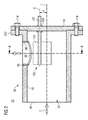
- the throttle valve 80 is illustrated in greater detail. Particularly, a longitudinal section of the throttle valve 80 is shown.
- the throttle valve 80 comprises a valve housing 90 and a valve shut-off element 100 rotatably disposed within the valve housing 90.
- the valve housing 90 may be an exhaust gas pipe into which the valve shut-off element 100 may be inserted.
- the valve housing 90 includes a side wall 92 being at least partially circumferential.
- the side wall 92 defines an exhaust gas passage 93 for directing exhaust gas through the valve housing 90.
- the side wall 92 comprises a circular cross-section.
- the valve housing 90 further comprises an inlet 94 disposed at a first end of the valve housing 90.
- the inlet 94 is configured to receive exhaust gas from the exhaust manifold 28.
- a flow direction of the exhaust gas is indicated by an arrow E being substantially parallel to a center axis L of the valve housing 90.
- the valve housing 90 comprises an outlet 96 which may be disposed at the side wall 92.
- the outlet 96 may be provided in the form of an opening extending through the side wall 92. It should be understood that the outlet 96 is configured to connect the first exhaust gas passage 93 with the outside of the throttle valve 80.
- the valve shut-off element 100 is eccentrically disposed within the valve housing 90. Particularly, the valve shut-off element 100 is rotatable about an rotational axis C.
- the rotational axis C is arranged in parallel to the center axis L, but spaced by a first offset a.
- the valve shut-off element 100 may include a shaft 102 and a valve body 104 attached to the shaft 102.
- the shaft 102 may be supported by a bearing 106, for example, a friction bearing.
- the bearing 106 may be disposed within a cover 110 and configured to allow rotation of the valve shut-off element 100 relative to the valve housing 90.
- the bearing 106 may be a roller bearing known in the art.
- the cover 110 may be sealingly mounted to the housing via a flange 112. For example, screws 114 may be used for fixing the cover 110 to the valve housing 90.
- the cover 110 may be configured to support the bearing 106, such that a sealing between the exhaust gas passage 93 and the outside of the housing 90 is created.
- bearing 106 may also be disposed within the valve housing 90.
- cover 110 may, for instance, be integrally formed with the valve housing 90.
- a distal end of the shaft 102 may be actuated from the outside of the throttle valve 80 by an actuation means (not shown).
- the throttle valve 80 further includes a valve seat 98.
- the valve seat 98 according to Fig. 2 is constituted by a cylindrical pipe.
- the valve seat 98 may be inserted into the outlet 96 and fixed to the valve housing 90 by, for example, pressure-fit.
- the valve seat 98 may be attached to the opening by, for instance, welding, soldering, adhering, or any other suitable means for fixedly attaching the valve seat 98 to the valve housing 90, specifically to the outlet 96.
- the valve seat 98 may be integrally formed with the valve housing 90.
- valve seat 98 may be constituted by any other means suitable for protruding into the exhaust gas passage 93 for providing a seat for the valve body 104 to ensure that the outlet 96 can be completely closed.
- the valve seat 98 may be a pipe inwardly attached to the circumferential wall 92 around the outlet 96.
- the valve seat 98 may include an internal end face 99 protruding into the exhaust gas passage 93 and configured to correspond substantially to the outer shape of the valve body 104 (see also, for example, Fig. 4 ). As illustrated in Fig. 1 , the internal end face 99 may be achieved by cutting, forming or otherwise providing an arcuate profile at the inner wall of a pipe (see Fig. 4 ).
- the valve shut-off element 100 of Fig. 2 is in a first position in which the valve body 104 is spaced from the valve seat 98. In the first position of the valve shut-off element, exhaust gas is allowed to pass through the outlet 96.
- the valve shut-off element 100 is further configured to be rotated into a second position in which the valve body 104 sealingly seats against the valve seat 98. In the second position, exhaust gas is restricted from passing through the outlet 96.
- valve shut-off element 100 When the valve shut-off element 100 is rotated within the valve housing 90 from the second position into the first position, such that the valve body 104 disengages the valve seat 98, the exhaust gas within the exhaust gas passage 93 is allowed to pass through the outlet 96 of the throttle valve 80, thereby bypassing the turbine 42 of Fig. 1 through the wastegate connection 82.
- the operational state in which the valve body 104 at least partially disengages the valve seat 98 may be also referred to as "ON state" of the throttle valve 80.
- valve shut-off element 100 When the valve shut-off element 100 is rotated towards its first position such that the valve body 104 fully engages the valve seat 98, the exhaust gas within the exhaust gas passage 93 is restricted from passing through the outlet 96 and, therefore, passes through the turbine 42 and drives the same.
- the operational state in which the valve body 104 fully engages the valve seat 98 may be also referred to as "OFF state" of the throttle valve 80. In the OFF state, the valve body 104 may sealingly engage the valve seat 98, thereby completely restricting the exhaust gas to pass through the outlet 96.
- soot contained within the exhaust gas may accumulate at the protruding internal end face 99 of the valve seat 98.
- the soot may accumulate at the interface of the valve body 104 engaging the valve seat 98. Such accumulated soot may cause the valve body 104 to get stuck at the valve seat 98 and, thus, may disturb proper operation of the throttle valve 80.
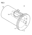
- a perspective view of the throttle valve 80 is shown.
- the valve shut-off element 100 is eccentrically disposed within the valve housing 90, and the valve seat 98 is inserted into the outlet 96.
- the shaft 102 may be actuated from the end side extending out of the valve housing 90 and through the cover 110.
- Fig. 3 does not depict some of the elements shown in Fig 2 .
- the bearing 98 and the screws 114 are not illustrated in Fig. 3 .
- FIG. 4 a cross-sectional view of the throttle valve 80 taken along a line A - A of Fig. 2 is shown.
- the rotational axis C of the valve shut-off element 100 is arranged within the valve housing 90 and has the first offset a with respect to the center axis L.
- the rotational axis C of the valve shut-off element 100 includes a second offset b with respect to the center axis L of the valve housing 90.
- the valve body 104 has an abutment face for engaging the valve seat and which may be arcuate.
- the valve body 104 may comprise at least a part of a cylinder.
- the valve body 104 includes an engaging surface 105 configured to engage the protruding internal end face 99 of the valve seat 98.
- the engaging surface 105 of the valve body 104 includes at least the same shape as the protruding internal end face 99 of the valve seat 98.
- the engaging surface and the valve seat may both be arcuate and may both have substantially the same radius of curvature.
- valve body 104 is a solid body. However, in some embodiments, the valve body 104 may be a hollow body.
- An engine control unit (not shown) may be configured to control the rotational movement of the valve shut-off element 100 and, therefore, the amount of exhaust gas passing through or bypassing the turbine 42.
- valve shut-off element 100 when the exhaust gas shall be restricted to pass through the turbine 42, the valve shut-off element 100 is rotated into the ON state, such that the valve body 104 disengages the valve seat 98. It is noted that it may be possible infinitely to adjust the amount of exhaust gas passing through the throttle valve 80 by only partially disengaging the valve body 104 with the valve seat 98.
- the engaging surface 105 may remove any deposits accumulated at the protruding internal end face 99 of the valve seat 98 due to the first and second offsets a, b.
- the detached deposits may be blown-off by the exhaust gas passing through the throttle valve 80.
- the engaging surface 105 also removes any deposits accumulated at the interface of the protruding internal end face 99 of the valve seat 98 and the engaging surface 105 of the valve body 104 due to the first and second offsets a, b.
- valve shut-off element 100 engages or disengages the valve seat 98, any accumulated deposits may be removed from the valve body 104 and/or the valve seat 98.
- valve shut-off element 100 In the case that the internal combustion engine 10 is operated in a stationary operation mode, such that the valve shut-off element 100 may not be rotated for a longer period of time, it is proposed to at least partially rotate the valve shut-off element 100 to clean the valve seat 98 and/or the valve body 104. For example, after an operation time of, for example, about four hours in a stationary operation without any actuation of the valve shut-off element 100, the valve shut-off element 100 may be rotated for cleaning the throttle valve 80. Specifically, when the throttle valve 80 is in the ON state, the valve shut-off element 100 may be rotated from the first position into the second position for a short period of time for removing any deposits accumulated at the valve seat 98.
- valve shut-off element 100 may be rotated from the second position into the first position for a short period of time for also removing any deposits accumulated at the valve seat 98 and the valve body 104. This may ensure proper operation of the throttle valve 80 and may prevent the valve shut-off element 100 from getting stuck in, for instance, the OFF state or the ON state.
- the self-cleaning throttle valve 80 is, therefore, able to enhance its lifetime.
- the disclosed throttle valve 80 may be used at internal combustion engines or dual fuel internal combustion engines of middle to large size.
- the internal combustion engine 10 may be sized and configured to be used e.g. in vessels, larger ships, or in power plants.
- the disclosed throttle valve 80 may be effective in any applications where exhaust gases are produced, which contain any pollution including soot, such as heavy fuel oil applications.
- internal combustion engine as used herein is not specifically restricted and comprises any engine, in which the combustion of a fuel occurs with an oxidizer to produce high temperature and pressure gases, which are directly applied to a movable component of the engine, such as pistons or turbine blades, and move it over a distance thereby generating mechanical energy.
- internal combustion engine comprises piston engines and turbines.
Landscapes
- Engineering & Computer Science (AREA)
- Chemical & Material Sciences (AREA)
- Combustion & Propulsion (AREA)
- Mechanical Engineering (AREA)
- General Engineering & Computer Science (AREA)
- Supercharger (AREA)
Abstract
The present disclosure generally relates to a self-cleaning throttle valve (80) to be used in an internal combustion engine. The disclosed throttle valve (80) may comprise a valve housing (90) including a side wall (92), an inlet (94), and an outlet (96) extending through the side wall (92). The throttle valve (90) may further comprise a valve seat (98) disposed at the outlet (96) and at least partially protruding into the valve housing (96), and a valve shut-off element (100) arranged within the valve housing (90) and being rotatable about a rotational axis (C) between a first position in which the valve shut-off element (100) is spaced apart from the valve seat (98) and a second position in which the valve shut-off element (100) engages the valve seat (98) and closes the outlet (96).
Description
- The present disclosure generally refers to a throttle valve for an internal combustion engine and a method for controlling a throttle valve of an internal combustion engine. Specifically, the present disclosure relates to a self cleaning throttle valve of an internal combustion engine.
- Throttle valves may be employed as kind of "ON/OFF" valves, such that, for instance, a fluid flow through the throttle valve may be controlled. In an "ON" state, the fluid flow may pass the throttle valve, whereas in an "OFF" state, the fluid flow may be restricted from passing through the throttle valve. Furthermore, throttle valves may also infinitely adjust the amount of fluid passing through the throttle valve.
- When being employed in an internal combustion engine, throttle valves may be used to control an exhaust gas flow. In some embodiments, throttle valves may be employed as wastegates, which may be configured to direct the exhaust gas flow around a turbine of a turbocharger of the internal combustion engine. In such case, the throttle valve is configured to control the amount of exhaust gas bypassing the turbine, and the amount of exhaust gas passing through the turbine, respectively.
- Exhaust gas of, for example, large internal combustion engines may contain soot which may affect operation of, for instance, throttle valves disposed within an exhaust gas system of the internal combustion engine. Particularly, soot may accumulate within the throttle valve and, thus, may disturb proper operation of the throttle valve.
-
US 2011/0000209 Al discloses a turbocharger comprising an actuator for opening and closing a wastegate duct. -
US 4 492 519 A discloses a turbocharger exhaust by-pass valve for selectively by-passing exhaust gases from the turbine rotor. The by-pass arrangement includes a valve plate which by a sliding action covers and uncovers a port that is essentially the same area as the exhaust gas inlet to the turbine housing. The sliding motion has a shearing action on any exhaust deposits. - The present disclosure is directed, at least in part, to improving or overcoming one or more aspects of prior systems.
- According to an aspect of the present disclosure, a throttle valve for an internal combustion engine may comprise a valve housing including a side wall, a first port, and a second port extending through the side wall. The throttle valve may further comprise a valve seat disposed at the second port and at least partially protruding into the valve housing, and a valve shut-off element arranged within the valve housing. The valve shut-off element may be rotatable about a rotational axis between a first position in which the valve shut-off element is spaced apart from the valve seat and a second position in which the valve shut-off element seats against the valve seat and closes the second port. The first and second ports may form an inlet and an outlet of the throttle valve. The first port may be configured as in the valve inlet and the second port may be configured as the valve outlet.
- According to another aspect of the present disclosure, an internal combustion engine may comprise a turbine configured to be driven by exhaust gas produced by the internal combustion engine, a wastegate connection configured to direct the exhaust gas around the turbine, and a throttle valve according to the present disclosure disposed within the wastegate connection.
- According to another aspect of the present disclosure, a method for removing deposits accumulated at a valve seat of a throttle valve to be used in an internal combustion engine may comprise rotating the valve shut-off element from a first position in which the valve shut-off element is spaced apart from the valve seat into a second position in which the valve shut-off element seats against the valve seat, and simultaneously removing any deposits accumulated on the valve seat by rotating the valve shut-off element from the first position into the second position.
- In some embodiments, the valve shut-off element may be further configured to, when the valve shut-off element is rotated from the second position into the first position, remove any deposits accumulated at the valve seat.
- According to an exemplary embodiment of a throttle valve, the valve shut-off element may include a valve body having an outer engaging surface configured to open and close the second port by engaging and disengaging the valve seat. The valve seat may be arcuate with a center of curvature and the outer engaging surface of the valve body may be arcuate. The curvature of the outer engaging surface may correspond to the curvature of the valve seat. The rotational axis of the valve shut-off element and the center of curvature of the valve seat are offset.
- In some embodiments, the valve shut-off element may be eccentrically arranged within the valve housing. In such embodiments, the valve shut-off element may be rotatable about a rotational axis arranged parallel to a center axis of the valve housing, but spaced by a first offset. In some other embodiments, the rotational axis may be further arranged parallel to the center axis of the valve housing, but spaced by a second offset perpendicular to the first offset.
- In some embodiments, the valve shut-off element may include a shaft and a valve body supported by the shaft, wherein the valve body may be configured to open and close the outlet by engaging and disengaging the valve seat.
- In some embodiments, the disclosed method may further comprise rotating the valve shut-off element from the second position into the first position, and simultaneously removing any deposits accumulated on the valve seat by rotating the valve shut-off element from the second position into the first position.
- Other features and aspects of this disclosure will be apparent from the following description and the accompanying drawings.
-
-
Fig. 1 shows a schematic diagram of an internal combustion engine comprising an exemplary disclosed throttle valve; -
Fig. 2 shows a longitudinal section of an exemplary disclosed throttle valve; -
Fig. 3 shows a schematic perspective view of the throttle valve ofFig. 2 ; and -
Fig. 4 shows a cross-section of the throttle valve ofFig. 2 taken along line A - A ofFig. 2 . - The following is a detailed description of exemplary embodiments of the present disclosure. The exemplary embodiments described therein and illustrated in the drawings are intended to teach the principles of the present disclosure, enabling those of ordinary skill in the art to implement and use the present disclosure in many different environments and for many different applications. Therefore, the exemplary embodiments are not intended to be, and should not be considered as, a limiting description of the scope of patent protection. Rather, the scope of patent protection shall be defined by the appended claims.
- The present disclosure may be based in part on a combination of closing the passage of exhaust gas through the throttle valve and simultaneously removing at least partly any deposits accumulated at the valve seat. This may ensure proper operation of the throttle valve.
- The present disclosure may be further based in part on the principle of rotating the valve shut-off element at regular periods of time, for example after a predetermined period of time. Consequently, the valve shut-off element may remove at least a part of any deposits accumulated at the valve seat within the predetermined period of time. Hence, a proper operation of the throttle valve may be maintained. The valve shut-off element may also be prevented from getting stuck within the valve housing during a stationary operation of the internal combustion engine. As a result, the lifetime of the throttle valve may be enhanced.
- Referring now to the drawings, an
internal combustion engine 10 is illustrated inFig. 1 . Theinternal combustion engine 10 may include features not shown, such as fuel systems, air systems, cooling systems, peripheries, drive train components, control systems etc. For the purposes of the present disclosure, theinternal combustion engine 10 is an internal combustion engine running on liquid fuel, such as diesel fuel or heavy fuel oil. One skilled in the art will recognize, however, that theinternal combustion engine 10 may be any type of engine (turbine, gas, natural gas, propane, dual fuel, etc.) that utilizes a mixture of fuel and air for combustion. Further, in some types of combustion engines, the mixture of fuel and air may be supplied to the combustion engine via an intake manifold. In other types of combustion engines, only air may be supplied to the combustion engine via the intake manifold, and fuel may be separately injected into each cylinder prior to combustion. - The
internal combustion engine 10 may be of any size, with any number of cylinders and in any configuration ("V", "in-line", etc.). Theinternal combustion engine 10 may be used to power any machine or other device, including locomotive applications, on-highway trucks or vehicles, off-highway machines, earth-moving equipment, generators, aerospace applications, marine applications, pumps, stationary equipment such as power plants, or other engine-powered applications. - Still referring to
Fig. 1 , theinternal combustion engine 10 comprises anengine block 20 including a bank ofcylinders 26A to 26D, at least one fuel tank (not shown), aturbocharger 40 associated with thecylinders 26A to 26D, and anintake assembly 12. - The
engine block 20 includes a crankcase (not shown) within which acrankshaft 6 indicated by a dot-dashed line is supported. Thecrankshaft 6 is connected to pistons (not shown) that are movable within each of thecylinders 26A to 26D during operation of theinternal combustion engine 10. - The
intake assembly 12 comprises anintake manifold 22 and a plurality ofintake ports 24A to 24D. Theintake manifold 22 defines a flow direction of charge air in the intake manifold 22 (shown by an arrow inFig. 1 ) and is fluidly connected to each of thecylinders 26A to 26D via a corresponding one of theinlet ports 24A to 24D of thecylinders 26A to 26D. Theinlet ports 24A to 24D are configured to receive charge air from theintake manifold 22. Generally, theinlet ports 24A to 24D may be formed at least in part in respective cylinder heads or in a common cylinder head (not shown) of thecylinders 26A to 26D. - An
exhaust manifold 28 is connected to each of thecylinders 26A to 26D. Each of thecylinders 26A to 26D is provided with at least one exhaust valve (not shown) configured to open and close a fluid connection between the combustion chamber of the corresponding cylinder and theexhaust manifold 28. - The
turbocharger 40 is configured to use the heat and pressure of the exhaust gas of theinternal combustion engine 10 to drive acompressor 44 for compressing the charge air prior to being supplied to thecylinders 26A to 26D. Specifically, exhaust gas passing aturbine 42 of theturbocharger 40 rotates theturbine 42, thereby decreasing in pressure and temperature. Thecompressor 44 is rotatably connected to theturbine 42 via acommon shaft 46 and driven by theturbine 42. - Charge air may be supplied to the
compressor 42 via anair intake 14 fluidly connected to an air system (not shown). Thecompressor 42 may compress the charge air to 7 to 8 bar at 180°C and a cooler 23 may cool the charge air from about 180°C to 45°C. After combustion, the exhaust gas may have a pressure of about 5 to 6 bar at a temperature in the range from about 450°C to 500°C. - Generally, an outlet of the
compressor 44 is fluidly connected to an inlet of theintake manifold 22 via acompressor connection 21. As shown inFig. 1 , an outlet of thecompressor 44 is connected to the inlet of theintake manifold 22 via the cooler 23. Athrottle valve 27 arranged downstream of the cooler 23 is configured to open or close the fluid connection between thecompressor connection 21 andintake manifold 22, thereby enabling or restricting the flow of charge air from thecompressor connection 21 into theintake manifold 22. - During operation of the
internal combustion engine 10, charge air is accordingly compressed and cooled before charging of thecylinders 26A to 26D. Within thecylinders 26A to 26D, further compression and, therefore, heating of the charge air is caused through the movement of the pistons. Then, an appropriate amount of fuel, e.g. diesel oil, marine diesel oil, heavy fuel oil or a mixture thereof is injected into thecylinders 26A to26D. Therein, the fuel is combusted with the compressed charged air and produce exhaust gases, which is discharged via theexhaust manifold 28. - An outlet of the
exhaust manifold 28 is fluidly connected to an inlet of theturbine 42. An outlet of theturbine 42 is fluidly connected to, for example, an exhaust gas treatment system (not shown) configured to treat the exhaust gas. - As further shown in
Fig. 1 , theinternal combustion engine 10 may be provided with a wastegate system including a throttle valve 80 (also called wastegate valve) fluidly connected to theexhaust manifold 28, and awastegate connection 82 bypassing theturbine 42. - By controlling the
throttle valve 80, the amount of exhaust gas passing theturbine 42 is controlled, which in turn controls the compression of charge air performed by thecompressor 44. - Referring now to
Fig. 2 , thethrottle valve 80 is illustrated in greater detail. Particularly, a longitudinal section of thethrottle valve 80 is shown. Thethrottle valve 80 comprises avalve housing 90 and a valve shut-offelement 100 rotatably disposed within thevalve housing 90. In some embodiments, thevalve housing 90 may be an exhaust gas pipe into which the valve shut-offelement 100 may be inserted. - The
valve housing 90 includes aside wall 92 being at least partially circumferential. Theside wall 92 defines anexhaust gas passage 93 for directing exhaust gas through thevalve housing 90. In the embodiment shown inFig. 2 , theside wall 92 comprises a circular cross-section. - The
valve housing 90 further comprises aninlet 94 disposed at a first end of thevalve housing 90. Theinlet 94 is configured to receive exhaust gas from theexhaust manifold 28. A flow direction of the exhaust gas is indicated by an arrow E being substantially parallel to a center axis L of thevalve housing 90. - The
valve housing 90 comprises anoutlet 96 which may be disposed at theside wall 92. Theoutlet 96 may be provided in the form of an opening extending through theside wall 92. It should be understood that theoutlet 96 is configured to connect the firstexhaust gas passage 93 with the outside of thethrottle valve 80. - The valve shut-off
element 100 is eccentrically disposed within thevalve housing 90. Particularly, the valve shut-offelement 100 is rotatable about an rotational axis C. The rotational axis C is arranged in parallel to the center axis L, but spaced by a first offset a. - The valve shut-off
element 100 may include ashaft 102 and avalve body 104 attached to theshaft 102. Theshaft 102 may be supported by abearing 106, for example, a friction bearing. Thebearing 106 may be disposed within acover 110 and configured to allow rotation of the valve shut-offelement 100 relative to thevalve housing 90. In some embodiments, thebearing 106 may be a roller bearing known in the art. - The
cover 110 may be sealingly mounted to the housing via aflange 112. For example, screws 114 may be used for fixing thecover 110 to thevalve housing 90. Thecover 110 may be configured to support thebearing 106, such that a sealing between theexhaust gas passage 93 and the outside of thehousing 90 is created. - One skilled in the art may recognize that the
bearing 106 may also be disposed within thevalve housing 90. In such embodiment, thecover 110 may, for instance, be integrally formed with thevalve housing 90. - For rotating the valve shut-off
element 100, a distal end of theshaft 102 may be actuated from the outside of thethrottle valve 80 by an actuation means (not shown). - The
throttle valve 80 further includes avalve seat 98. Thevalve seat 98 according toFig. 2 is constituted by a cylindrical pipe. Thevalve seat 98 may be inserted into theoutlet 96 and fixed to thevalve housing 90 by, for example, pressure-fit. In some embodiments, thevalve seat 98 may be attached to the opening by, for instance, welding, soldering, adhering, or any other suitable means for fixedly attaching thevalve seat 98 to thevalve housing 90, specifically to theoutlet 96. In some other embodiments, thevalve seat 98 may be integrally formed with thevalve housing 90. - In some embodiments, the
valve seat 98 may be constituted by any other means suitable for protruding into theexhaust gas passage 93 for providing a seat for thevalve body 104 to ensure that theoutlet 96 can be completely closed. For example, thevalve seat 98 may be a pipe inwardly attached to thecircumferential wall 92 around theoutlet 96. - The
valve seat 98 may include aninternal end face 99 protruding into theexhaust gas passage 93 and configured to correspond substantially to the outer shape of the valve body 104 (see also, for example,Fig. 4 ). As illustrated inFig. 1 , theinternal end face 99 may be achieved by cutting, forming or otherwise providing an arcuate profile at the inner wall of a pipe (seeFig. 4 ). - The valve shut-off
element 100 ofFig. 2 is in a first position in which thevalve body 104 is spaced from thevalve seat 98. In the first position of the valve shut-off element, exhaust gas is allowed to pass through theoutlet 96. The valve shut-offelement 100 is further configured to be rotated into a second position in which thevalve body 104 sealingly seats against thevalve seat 98. In the second position, exhaust gas is restricted from passing through theoutlet 96. - When the valve shut-off
element 100 is rotated within thevalve housing 90 from the second position into the first position, such that thevalve body 104 disengages thevalve seat 98, the exhaust gas within theexhaust gas passage 93 is allowed to pass through theoutlet 96 of thethrottle valve 80, thereby bypassing theturbine 42 ofFig. 1 through thewastegate connection 82. The operational state in which thevalve body 104 at least partially disengages thevalve seat 98 may be also referred to as "ON state" of thethrottle valve 80. - When the valve shut-off
element 100 is rotated towards its first position such that thevalve body 104 fully engages thevalve seat 98, the exhaust gas within theexhaust gas passage 93 is restricted from passing through theoutlet 96 and, therefore, passes through theturbine 42 and drives the same. The operational state in which thevalve body 104 fully engages thevalve seat 98 may be also referred to as "OFF state" of thethrottle valve 80. In the OFF state, thevalve body 104 may sealingly engage thevalve seat 98, thereby completely restricting the exhaust gas to pass through theoutlet 96. - In some operations, soot contained within the exhaust gas may accumulate at the protruding internal end face 99 of the
valve seat 98. In some other operations, for example, during the OFF state of thethrottle valve 80, the soot may accumulate at the interface of thevalve body 104 engaging thevalve seat 98. Such accumulated soot may cause thevalve body 104 to get stuck at thevalve seat 98 and, thus, may disturb proper operation of thethrottle valve 80. - Referring to
Fig. 3 , a perspective view of thethrottle valve 80 is shown. As illustrated, the valve shut-offelement 100 is eccentrically disposed within thevalve housing 90, and thevalve seat 98 is inserted into theoutlet 96. For rotating the valve shut-off element, theshaft 102 may be actuated from the end side extending out of thevalve housing 90 and through thecover 110. It should be noted thatFig. 3 does not depict some of the elements shown inFig 2 . For example, thebearing 98 and thescrews 114 are not illustrated inFig. 3 . - Referring now to
Fig. 4 , a cross-sectional view of thethrottle valve 80 taken along a line A - A ofFig. 2 is shown. As depicted inFig. 4 , the rotational axis C of the valve shut-offelement 100 is arranged within thevalve housing 90 and has the first offset a with respect to the center axis L. The rotational axis C of the valve shut-offelement 100 includes a second offset b with respect to the center axis L of thevalve housing 90. - The
valve body 104 has an abutment face for engaging the valve seat and which may be arcuate. In some embodiments, thevalve body 104 may comprise at least a part of a cylinder. Thevalve body 104 includes an engaging surface 105 configured to engage the protruding internal end face 99 of thevalve seat 98. For fully closing theoutlet 96, the engaging surface 105 of thevalve body 104 includes at least the same shape as the protruding internal end face 99 of thevalve seat 98. The engaging surface and the valve seat may both be arcuate and may both have substantially the same radius of curvature. - In the embodiment shown in
Figs. 3 and4 , thevalve body 104 is a solid body. However, in some embodiments, thevalve body 104 may be a hollow body. - In the following, operation of the
throttle valve 80 during operation of theinternal combustion engine 10 is described with reference toFigs. 1 to 4 . - After combustion of the fuel/air mixture within the
cylinders 24A to 24D, the exhaust gas may be released into theexhaust manifold 28. An engine control unit (not shown) may be configured to control the rotational movement of the valve shut-offelement 100 and, therefore, the amount of exhaust gas passing through or bypassing theturbine 42. - Particularly, when the exhaust gas shall be restricted to pass through the
turbine 42, the valve shut-offelement 100 is rotated into the ON state, such that thevalve body 104 disengages thevalve seat 98. It is noted that it may be possible infinitely to adjust the amount of exhaust gas passing through thethrottle valve 80 by only partially disengaging thevalve body 104 with thevalve seat 98. - For example, when rotating the valve shut-off
element 100 in a counter-clockwise direction inFig. 4 , i.e. from the first position into the second position, such that thethrottle valve 80 is in the OFF state and theoutlet 96 is closed, the engaging surface 105 may remove any deposits accumulated at the protruding internal end face 99 of thevalve seat 98 due to the first and second offsets a, b. In a subsequent opening process, the detached deposits may be blown-off by the exhaust gas passing through thethrottle valve 80. - For instance, when rotating the valve shut-off
element 100 engaging thevalve seat 98 in a clockwise direction inFig. 4 , i.e. from the second position into the first position, such that thethrottle valve 80 is in the ON state and theoutlet 96 is opened, the engaging surface 105 also removes any deposits accumulated at the interface of the protruding internal end face 99 of thevalve seat 98 and the engaging surface 105 of thevalve body 104 due to the first and second offsets a, b. - Therefore, when the valve shut-off
element 100 engages or disengages thevalve seat 98, any accumulated deposits may be removed from thevalve body 104 and/or thevalve seat 98. - In the case that the
internal combustion engine 10 is operated in a stationary operation mode, such that the valve shut-offelement 100 may not be rotated for a longer period of time, it is proposed to at least partially rotate the valve shut-offelement 100 to clean thevalve seat 98 and/or thevalve body 104. For example, after an operation time of, for example, about four hours in a stationary operation without any actuation of the valve shut-offelement 100, the valve shut-offelement 100 may be rotated for cleaning thethrottle valve 80. Specifically, when thethrottle valve 80 is in the ON state, the valve shut-offelement 100 may be rotated from the first position into the second position for a short period of time for removing any deposits accumulated at thevalve seat 98. - Similarly, when the
throttle valve 80 is in the OFF state, the valve shut-offelement 100 may be rotated from the second position into the first position for a short period of time for also removing any deposits accumulated at thevalve seat 98 and thevalve body 104. This may ensure proper operation of thethrottle valve 80 and may prevent the valve shut-offelement 100 from getting stuck in, for instance, the OFF state or the ON state. The self-cleaningthrottle valve 80 is, therefore, able to enhance its lifetime. - The disclosed
throttle valve 80 may be used at internal combustion engines or dual fuel internal combustion engines of middle to large size. In particular, theinternal combustion engine 10 may be sized and configured to be used e.g. in vessels, larger ships, or in power plants. The disclosedthrottle valve 80 may be effective in any applications where exhaust gases are produced, which contain any pollution including soot, such as heavy fuel oil applications. - In addition, the term "internal combustion engine" as used herein is not specifically restricted and comprises any engine, in which the combustion of a fuel occurs with an oxidizer to produce high temperature and pressure gases, which are directly applied to a movable component of the engine, such as pistons or turbine blades, and move it over a distance thereby generating mechanical energy. Thus, as used herein, the term "internal combustion engine" comprises piston engines and turbines.
- Although the preferred embodiments of this invention have been described herein, improvements and modifications may be incorporated without departing from the scope of the following claims.
Claims (15)
- A throttle valve (80) for an internal combustion engine (10), comprising:a valve housing (90) including a side wall (92), a first port (94), and a second port (96) extending through the side wall (92);a valve seat (98) disposed at the second port (96) and at least partially protruding into the valve housing (90); anda valve shut-off element (100) arranged within the valve housing (90) and being rotatable about a rotational axis (C) between a first position in which the valve shut-off element (100) is spaced apart from the valve seat (98) and a second position in which the valve shut-off element (100) engages the valve seat (98) and closes the second port (96).
- The throttle valve (80) of claim 1, wherein the valve shut-off element (100) includes a valve body (104) having an outer engaging surface (105) configured to open and close the second port (96) by engaging and disengaging the valve seat (98).
- The throttle valve (80) of claim 2, wherein:the valve seat (98) is arcuate with a center of curvature;the outer engaging surface (105) of the valve body (104) is arcuate, wherein the curvature of the outer engaging surface (105) corresponds to the curvature of the valve seat (98);the rotational axis (C) of the valve shut-off element (100) and the center of curvature of the valve seat (98) being offset.
- The throttle valve (80) of any one of the preceding claims, wherein the valve shut-off element (100) is eccentrically arranged with respect to a center axis (L) of the valve housing (90).
- The throttle valve (80) of claim 4, wherein the rotational axis (C) of the valve shut-off element (100) is arranged in parallel to the center axis (L) of the valve housing (90), but spaced by a first offset (a).
- The throttle valve (80) of claim 5, wherein the rotational axis (C) of the valve shut-off element (100) is arranged in parallel to the center axis (L) of the valve housing (90), but spaced by a second offset (b) perpendicular to the first offset (a).
- The throttle valve (80) of any one of claims 2 to 6, wherein the valve shut-off element (100) includes a shaft (102), the valve body (104) being supported by the shaft (102).
- The throttle valve (80) of any one of claims 2 to 7, wherein the valve body (104) has at least a partially cylindrical shape.
- The throttle valve (80) of claim 7, further comprising a bearing (106) configured to support the shaft (102) thereby enabling a rotational movement of the valve body (104) within the valve housing (90).
- The throttle valve (80) of any one of the preceding claims, further comprising a cover (110) configured to be mounted to the valve housing (90), thereby closing the valve housing (90) at an end opposite to the firs port (94), wherein the cover (110) is further configured to support the bearing (106).
- The throttle valve (80) of any one of the preceding claims, wherein the valve seat (98) is a pipe inserted into the outlet (96).
- The throttle valve (80) of any one of the preceding claims, wherein the valve shut-off element (100) is configured to, when the valve shut-off element (100) is rotated from the first position into the second position, remove any deposits accumulated at the valve seat (98) and, when the valve shut-off element (100) is rotated from the second position into the first position, remove any deposits accumulated at the valve seat (98).
- An internal combustion engine (10) comprising:a turbine (42) configured to be driven by exhaust gas produced by the internal combustion engine (10);a wastegate connection (82) configured to direct the exhaust gas around the turbine (42); anda throttle valve (80) of any one of the preceding claims disposed within the wastegate connection (82).
- A method for removing deposits accumulated at a valve seat (98) of a throttle valve (80) to be used in an internal combustion engine (10), the throttle valve (80) comprising a valve housing (90) and a valve shut-off element (100) rotatably arranged within the valve housing (90), the method comprising:rotating the valve shut-off element (100) from a first position in which the valve shut-off element (100) is spaced apart from the valve seat (98) into a second position in which the valve shut-off element (100) engages the valve seat (98); andsimultaneously removing any deposits accumulated on the valve seat (98) by rotating the valve shut-off element (100) from the first position into the second position.
- The method of claim 14, further comprising:rotating the valve shut-off element (100) from the second position into the first position; andsimultaneously removing any deposits accumulated on the valve seat (98) by rotating the valve shut-off element (100) from the second position into the first position.
Priority Applications (1)
| Application Number | Priority Date | Filing Date | Title |
|---|---|---|---|
| EP13150306.2A EP2752569A1 (en) | 2013-01-04 | 2013-01-04 | Throttle valve for internal combustion engines |
Applications Claiming Priority (1)
| Application Number | Priority Date | Filing Date | Title |
|---|---|---|---|
| EP13150306.2A EP2752569A1 (en) | 2013-01-04 | 2013-01-04 | Throttle valve for internal combustion engines |
Publications (1)
| Publication Number | Publication Date |
|---|---|
| EP2752569A1 true EP2752569A1 (en) | 2014-07-09 |
Family
ID=47630143
Family Applications (1)
| Application Number | Title | Priority Date | Filing Date |
|---|---|---|---|
| EP13150306.2A Withdrawn EP2752569A1 (en) | 2013-01-04 | 2013-01-04 | Throttle valve for internal combustion engines |
Country Status (1)
| Country | Link |
|---|---|
| EP (1) | EP2752569A1 (en) |
Cited By (1)
| Publication number | Priority date | Publication date | Assignee | Title |
|---|---|---|---|---|
| JP2018141401A (en) * | 2017-02-28 | 2018-09-13 | 株式会社Subaru | EGR valve and EGR device |
Citations (11)
| Publication number | Priority date | Publication date | Assignee | Title |
|---|---|---|---|---|
| US1028134A (en) * | 1911-05-20 | 1912-06-04 | James H Raymaker | Valve. |
| US4171689A (en) * | 1977-01-29 | 1979-10-23 | Robert Bosch Gmbh | Device for the control of gas admissions into the induction manifold of an internal combustion engine |
| US4222356A (en) * | 1978-09-13 | 1980-09-16 | Toyota Jidosha Kogyo Kabushiki Kaisha | Exhaust gas recirculation for a diesel engine |
| US4237837A (en) * | 1978-09-13 | 1980-12-09 | Toyota Jidosha Kogyo Kabushiki Kaisha | Exhaust gas recirculation for a diesel engine |
| US4428356A (en) * | 1982-05-14 | 1984-01-31 | Robert Bosch Gmbh | Device for controlling at least one throttle diameter in a control line |
| US4492519A (en) | 1979-02-15 | 1985-01-08 | Wallace Murray Corporation | Turbocharger exhaust gas by-pass valve |
| DE19914213A1 (en) * | 1999-03-29 | 2000-10-05 | Boysen Friedrich Gmbh Co Kg | Locking device for exhaust gas flow, with stop in exhaust gas channel against which locking flap is stopped when it closes exhaust gas flow |
| DE102006055818A1 (en) * | 2006-11-27 | 2008-05-29 | Ford Global Technologies, LLC, Dearborn | Exhaust-gas turbocharger for loading e.g. diesel engine, has spring unit that is arranged such that prestressing force exerted on continuously adjustable flap has digressive course over pivoting angle based on closed position of flap |
| EP2236871A1 (en) * | 2009-03-31 | 2010-10-06 | Pierburg GmbH | Flap valve |
| EP2236805A2 (en) * | 2009-03-31 | 2010-10-06 | Pierburg GmbH | Flap valve |
| US20110000209A1 (en) | 2008-02-27 | 2011-01-06 | Continental Automotive Gmbh | Turbocharger comprising an actuator for opening and closing a wastegate duct |
-
2013
- 2013-01-04 EP EP13150306.2A patent/EP2752569A1/en not_active Withdrawn
Patent Citations (11)
| Publication number | Priority date | Publication date | Assignee | Title |
|---|---|---|---|---|
| US1028134A (en) * | 1911-05-20 | 1912-06-04 | James H Raymaker | Valve. |
| US4171689A (en) * | 1977-01-29 | 1979-10-23 | Robert Bosch Gmbh | Device for the control of gas admissions into the induction manifold of an internal combustion engine |
| US4222356A (en) * | 1978-09-13 | 1980-09-16 | Toyota Jidosha Kogyo Kabushiki Kaisha | Exhaust gas recirculation for a diesel engine |
| US4237837A (en) * | 1978-09-13 | 1980-12-09 | Toyota Jidosha Kogyo Kabushiki Kaisha | Exhaust gas recirculation for a diesel engine |
| US4492519A (en) | 1979-02-15 | 1985-01-08 | Wallace Murray Corporation | Turbocharger exhaust gas by-pass valve |
| US4428356A (en) * | 1982-05-14 | 1984-01-31 | Robert Bosch Gmbh | Device for controlling at least one throttle diameter in a control line |
| DE19914213A1 (en) * | 1999-03-29 | 2000-10-05 | Boysen Friedrich Gmbh Co Kg | Locking device for exhaust gas flow, with stop in exhaust gas channel against which locking flap is stopped when it closes exhaust gas flow |
| DE102006055818A1 (en) * | 2006-11-27 | 2008-05-29 | Ford Global Technologies, LLC, Dearborn | Exhaust-gas turbocharger for loading e.g. diesel engine, has spring unit that is arranged such that prestressing force exerted on continuously adjustable flap has digressive course over pivoting angle based on closed position of flap |
| US20110000209A1 (en) | 2008-02-27 | 2011-01-06 | Continental Automotive Gmbh | Turbocharger comprising an actuator for opening and closing a wastegate duct |
| EP2236871A1 (en) * | 2009-03-31 | 2010-10-06 | Pierburg GmbH | Flap valve |
| EP2236805A2 (en) * | 2009-03-31 | 2010-10-06 | Pierburg GmbH | Flap valve |
Cited By (1)
| Publication number | Priority date | Publication date | Assignee | Title |
|---|---|---|---|---|
| JP2018141401A (en) * | 2017-02-28 | 2018-09-13 | 株式会社Subaru | EGR valve and EGR device |
Similar Documents
| Publication | Publication Date | Title |
|---|---|---|
| CN102713195B (en) | The turbosupercharger of direct UNICOM | |
| JP4706775B2 (en) | Intake device for internal combustion engine | |
| JP5304949B2 (en) | Turbocharger | |
| EP2687696A1 (en) | Compact exhaust gas treatment system and method of operating the same | |
| CA2968856C (en) | Rotary internal combustion engine with seal lubrication | |
| JP5699662B2 (en) | Exhaust device for internal combustion engine | |
| US8783015B2 (en) | Shared EGR system and method for a dual-module engine | |
| US20130186378A1 (en) | Engine breathing system valve and seal | |
| WO2014032783A1 (en) | Wastegate exhaust gas line for v-type internal combustion engines | |
| EP2733325A1 (en) | Throttle valve for internal combustion engines | |
| WO2014007374A1 (en) | Engine device | |
| US20130081392A1 (en) | Exhaust gas recirculation in a reciprocating engine | |
| US11111884B2 (en) | Spark-ignition internal combustion engine having urea introduction device and method for operating an internal combustion engine of this type | |
| EP2703618A1 (en) | Control system for throttle valves | |
| US20230313727A1 (en) | Engine | |
| JP5742538B2 (en) | Exhaust device for internal combustion engine | |
| JP7319636B2 (en) | Blower | |
| JP5905093B2 (en) | Supercharged internal combustion engine | |
| EP3696386B1 (en) | Valve assembly for a dual volute turbocharger and dual volute turbocharger including the same | |
| WO2019009842A2 (en) | An engine cycle with orientable heating property | |
| JP7834876B2 (en) | Automobiles, especially internal combustion engines of powered vehicles | |
| EP2761141B1 (en) | Turbine washing for charged internal combustion engines | |
| EP1923550A2 (en) | Bypass assembly for a charge-air cooler | |
| CN112805461A (en) | Exhaust turbine of an exhaust gas turbocharger with a sealed wastegate valve arrangement, and exhaust gas turbocharger | |
| EP2703621B1 (en) | Exhaust gas line for V-type internal combustion engines |
Legal Events
| Date | Code | Title | Description |
|---|---|---|---|
| 17P | Request for examination filed |
Effective date: 20130104 |
|
| AK | Designated contracting states |
Kind code of ref document: A1 Designated state(s): AL AT BE BG CH CY CZ DE DK EE ES FI FR GB GR HR HU IE IS IT LI LT LU LV MC MK MT NL NO PL PT RO RS SE SI SK SM TR |
|
| AX | Request for extension of the european patent |
Extension state: BA ME |
|
| PUAI | Public reference made under article 153(3) epc to a published international application that has entered the european phase |
Free format text: ORIGINAL CODE: 0009012 |
|
| STAA | Information on the status of an ep patent application or granted ep patent |
Free format text: STATUS: THE APPLICATION IS DEEMED TO BE WITHDRAWN |
|
| 18D | Application deemed to be withdrawn |
Effective date: 20150110 |